

Page 1

Centellis 2000 Shelf Release 3.0
Installation and Use
P/N: 6806800L99G
May 2014
Page 2

©
Copyright 2014 Artesyn Embedded Technologies, Inc.
All rights reserved.
Trademarks
Artesyn Embedded Technologies, Artesyn and the Artesyn Embedded Technologies logo are trademarks and service marks of
Artesyn Embedded Technologies, Inc.© 2014 Artesyn Embedded Technologies, Inc. All other product or service names are the
property of their respective owners.
Intel® is a trademark or registered trademark of Intel Corporation or its subsidiaries in the United States and other countries.
Java™ and all other Java-based marks are trademarks or registered trademarks of Oracle America, Inc. in the U.S. and other countries.
Microsoft®, Windows® and Windows Me® are registered trademarks of Microsoft Corporation; and Windows XP™ is a trademark of
Microsoft Corporation.
PICMG®, CompactPCI®, AdvancedTCA™ and the PICMG, CompactPCI and AdvancedTCA logos are registered trademarks of the PCI
Industrial Computer Manufacturers Group.
UNIX® is a registered trademark of The Open Group in the United States and other countries.
Notice
While reasonable efforts have been made to assure the accuracy of this document, Artesyn assumes no liability resulting from any
omissions in this document, or from the use of the information obtained therein. Artesyn reserves the right to revise this document
and to make changes from time to time in the content hereof without obligation of Artesyn to notify any person of such revision or
changes.
Electronic versions of this material may be read online, downloaded for personal use, or referenced in another document as a URL to
an Artesyn website. The text itself may not be published commercially in print or electronic form, edited, translated, or otherwise
altered without the permission of Artesyn.
It is possible that this publication may contain reference to or information about Artesyn products (machines and programs),
programming, or services that are not available in your country. Such references or information must not be construed to mean that
Artesyn intends to announce such Artesyn products, programming, or services in your country.
Limited and Restricted Rights Legend
If the documentation contained herein is supplied, directly or indirectly, to the U.S. Government, the following notice shall apply
unless otherwise agreed to in writing by Artesyn.
Use, duplication, or disclosure by the Government is subject to restrictions as set forth in subparagraph (b)(3) of the Rights in
Technical Data clause at DFARS 252.227-7013 (Nov. 1995) and of the Rights in Noncommercial Computer Software and
Documentation clause at DFARS 252.227-7014 (Jun. 1995).
Contact Address
Artesyn Embedded Technologies Artesyn Embedded Technologies
Marketing Communications
2900 S. Diablo Way, Suite 190
Tempe, Arizona 85282
Lilienthalstr. 17-19
85579 Neubiberg/Munich
Germany
Page 3

Contents
About this Manual . . . . . . . . . . . . . . . . . . . . . . . . . . . . . . . . . . . . . . . . . . . . . . . . . . . . . . . . . . . . . . . . . . . . . . . 13
Safety Notes . . . . . . . . . . . . . . . . . . . . . . . . . . . . . . . . . . . . . . . . . . . . . . . . . . . . . . . . . . . . . . . . . . . . . . . . . . . . . 21
Sicherheitshinweise . . . . . . . . . . . . . . . . . . . . . . . . . . . . . . . . . . . . . . . . . . . . . . . . . . . . . . . . . . . . . . . . . . . . . . 35
1 System Overview. . . . . . . . . . . . . . . . . . . . . . . . . . . . . . . . . . . . . . . . . . . . . . . . . . . . . . . . . . . . . . . . . . . . . 49
1.1 Description . . . . . . . . . . . . . . . . . . . . . . . . . . . . . . . . . . . . . . . . . . . . . . . . . . . . . . . . . . . . . . . . . . . . . . . . 49
1.1.1 Shelf. . . . . . . . . . . . . . . . . . . . . . . . . . . . . . . . . . . . . . . . . . . . . . . . . . . . . . . . . . . . . . . . . . . . . . . . 51
1.1.2 Backplane . . . . . . . . . . . . . . . . . . . . . . . . . . . . . . . . . . . . . . . . . . . . . . . . . . . . . . . . . . . . . . . . . . . 52
1.1.3 Shelf Manager and Hub Board . . . . . . . . . . . . . . . . . . . . . . . . . . . . . . . . . . . . . . . . . . . . . . . . . 52
1.1.4 Node Slots . . . . . . . . . . . . . . . . . . . . . . . . . . . . . . . . . . . . . . . . . . . . . . . . . . . . . . . . . . . . . . . . . . 54
1.1.5 Rear Transition Modules . . . . . . . . . . . . . . . . . . . . . . . . . . . . . . . . . . . . . . . . . . . . . . . . . . . . . . 54
1.1.6 Power Inlet Modules. . . . . . . . . . . . . . . . . . . . . . . . . . . . . . . . . . . . . . . . . . . . . . . . . . . . . . . . . . 54
1.1.7 AC Power Supply Unit and DC Power Entry Modules . . . . . . . . . . . . . . . . . . . . . . . . . . . . . . 54
1.1.8 Fan Trays. . . . . . . . . . . . . . . . . . . . . . . . . . . . . . . . . . . . . . . . . . . . . . . . . . . . . . . . . . . . . . . . . . . . 54
1.1.9 Air Filters. . . . . . . . . . . . . . . . . . . . . . . . . . . . . . . . . . . . . . . . . . . . . . . . . . . . . . . . . . . . . . . . . . . . 54
1.1.10 User Card Slots . . . . . . . . . . . . . . . . . . . . . . . . . . . . . . . . . . . . . . . . . . . . . . . . . . . . . . . . . . . . . . 55
1.2 System Management . . . . . . . . . . . . . . . . . . . . . . . . . . . . . . . . . . . . . . . . . . . . . . . . . . . . . . . . . . . . . . . 57
1.3 Shelf Management . . . . . . . . . . . . . . . . . . . . . . . . . . . . . . . . . . . . . . . . . . . . . . . . . . . . . . . . . . . . . . . . . 59
1.4 Standard Compliances . . . . . . . . . . . . . . . . . . . . . . . . . . . . . . . . . . . . . . . . . . . . . . . . . . . . . . . . . . . . . . 61
1.5 Ordering Information . . . . . . . . . . . . . . . . . . . . . . . . . . . . . . . . . . . . . . . . . . . . . . . . . . . . . . . . . . . . . . . 66
2 Site Preparation . . . . . . . . . . . . . . . . . . . . . . . . . . . . . . . . . . . . . . . . . . . . . . . . . . . . . . . . . . . . . . . . . . . . . . 71
2.1 Overview . . . . . . . . . . . . . . . . . . . . . . . . . . . . . . . . . . . . . . . . . . . . . . . . . . . . . . . . . . . . . . . . . . . . . . . . . . 71
2.2 Site Planning Considerations . . . . . . . . . . . . . . . . . . . . . . . . . . . . . . . . . . . . . . . . . . . . . . . . . . . . . . . . . 71
2.2.1 Receiving and Unpacking the System . . . . . . . . . . . . . . . . . . . . . . . . . . . . . . . . . . . . . . . . . . . 72
2.2.2 Site and Installation Planning . . . . . . . . . . . . . . . . . . . . . . . . . . . . . . . . . . . . . . . . . . . . . . . . . . 73
2.3 Requirements . . . . . . . . . . . . . . . . . . . . . . . . . . . . . . . . . . . . . . . . . . . . . . . . . . . . . . . . . . . . . . . . . . . . . . 73
2.3.1 Environmental Requirements. . . . . . . . . . . . . . . . . . . . . . . . . . . . . . . . . . . . . . . . . . . . . . . . . . 74
2.3.2 Power Requirements . . . . . . . . . . . . . . . . . . . . . . . . . . . . . . . . . . . . . . . . . . . . . . . . . . . . . . . . . 76
2.4 Dimensions and Weight . . . . . . . . . . . . . . . . . . . . . . . . . . . . . . . . . . . . . . . . . . . . . . . . . . . . . . . . . . . . . 78
2.5 Mounting Options . . . . . . . . . . . . . . . . . . . . . . . . . . . . . . . . . . . . . . . . . . . . . . . . . . . . . . . . . . . . . . . . . . 78
2.6 Cooling Considerations . . . . . . . . . . . . . . . . . . . . . . . . . . . . . . . . . . . . . . . . . . . . . . . . . . . . . . . . . . . . . 80
Centellis 2000 Shelf Release 3.0 Installation and Use (6806800L99G)
3
Page 4

2.7 Acoustic Noise Control . . . . . . . . . . . . . . . . . . . . . . . . . . . . . . . . . . . . . . . . . . . . . . . . . . . . . . . . . . . . . . 81
3 System Installation . . . . . . . . . . . . . . . . . . . . . . . . . . . . . . . . . . . . . . . . . . . . . . . . . . . . . . . . . . . . . . . . . . . 83
3.1 Overview . . . . . . . . . . . . . . . . . . . . . . . . . . . . . . . . . . . . . . . . . . . . . . . . . . . . . . . . . . . . . . . . . . . . . . . . . . 83
3.2 Before Installation . . . . . . . . . . . . . . . . . . . . . . . . . . . . . . . . . . . . . . . . . . . . . . . . . . . . . . . . . . . . . . . . . . 83
3.2.1 Type Label Location . . . . . . . . . . . . . . . . . . . . . . . . . . . . . . . . . . . . . . . . . . . . . . . . . . . . . . . . . . 83
3.2.2 Requirements . . . . . . . . . . . . . . . . . . . . . . . . . . . . . . . . . . . . . . . . . . . . . . . . . . . . . . . . . . . . . . . 83
3.2.3 Tools You Will Need . . . . . . . . . . . . . . . . . . . . . . . . . . . . . . . . . . . . . . . . . . . . . . . . . . . . . . . . . . 84
3.2.4 Torque Values . . . . . . . . . . . . . . . . . . . . . . . . . . . . . . . . . . . . . . . . . . . . . . . . . . . . . . . . . . . . . . . 84
3.3 Installation . . . . . . . . . . . . . . . . . . . . . . . . . . . . . . . . . . . . . . . . . . . . . . . . . . . . . . . . . . . . . . . . . . . . . . . . 85
3.3.1 Installing the System in a Rack . . . . . . . . . . . . . . . . . . . . . . . . . . . . . . . . . . . . . . . . . . . . . . . . . 86
3.3.2 Ground System/Bonding. . . . . . . . . . . . . . . . . . . . . . . . . . . . . . . . . . . . . . . . . . . . . . . . . . . . . . 89
3.3.3 Powering-Up the System. . . . . . . . . . . . . . . . . . . . . . . . . . . . . . . . . . . . . . . . . . . . . . . . . . . . . . 90
3.3.3.1 AC System Startup Procedure . . . . . . . . . . . . . . . . . . . . . . . . . . . . . . . . . . . . . . . . 91
3.3.3.2 DC System Startup Procedure . . . . . . . . . . . . . . . . . . . . . . . . . . . . . . . . . . . . . . . . 93
3.4 Removal . . . . . . . . . . . . . . . . . . . . . . . . . . . . . . . . . . . . . . . . . . . . . . . . . . . . . . . . . . . . . . . . . . . . . . . . . . . 97
3.4.1 Powering Down the System . . . . . . . . . . . . . . . . . . . . . . . . . . . . . . . . . . . . . . . . . . . . . . . . . . . 97
3.4.2 Disconnecting the System from Power Feed. . . . . . . . . . . . . . . . . . . . . . . . . . . . . . . . . . . . . 98
3.4.2.1 AC System Disconnection Procedure . . . . . . . . . . . . . . . . . . . . . . . . . . . . . . . . . . 98
3.4.2.2 DC System Disconnection Procedure . . . . . . . . . . . . . . . . . . . . . . . . . . . . . . . . . . 99
3.4.3 Removing the System . . . . . . . . . . . . . . . . . . . . . . . . . . . . . . . . . . . . . . . . . . . . . . . . . . . . . . . 100
4 FRU Installation . . . . . . . . . . . . . . . . . . . . . . . . . . . . . . . . . . . . . . . . . . . . . . . . . . . . . . . . . . . . . . . . . . . . . 101
4.1 Overview . . . . . . . . . . . . . . . . . . . . . . . . . . . . . . . . . . . . . . . . . . . . . . . . . . . . . . . . . . . . . . . . . . . . . . . . . 101
4.2 Installing and Removing RTMs and Blades . . . . . . . . . . . . . . . . . . . . . . . . . . . . . . . . . . . . . . . . . . . .101
4.3 Replacing the Shelf Manager and Hub Board . . . . . . . . . . . . . . . . . . . . . . . . . . . . . . . . . . . . . . . . . . 102
4.4 Covering Unused Slots . . . . . . . . . . . . . . . . . . . . . . . . . . . . . . . . . . . . . . . . . . . . . . . . . . . . . . . . . . . . . 105
4.5 Replacing AC Power Supply Units . . . . . . . . . . . . . . . . . . . . . . . . . . . . . . . . . . . . . . . . . . . . . . . . . . . . 105
4.6 Replacing DC Power Entry Modules . . . . . . . . . . . . . . . . . . . . . . . . . . . . . . . . . . . . . . . . . . . . . . . . . . 108
4.7 Installing Circuit Breaker Cover for DC PEMs . . . . . . . . . . . . . . . . . . . . . . . . . . . . . . . . . . . . . . . . . . 112
4.8 Replacing Fan Trays . . . . . . . . . . . . . . . . . . . . . . . . . . . . . . . . . . . . . . . . . . . . . . . . . . . . . . . . . . . . . . . . 114
4.9 Maintaining Air Filters . . . . . . . . . . . . . . . . . . . . . . . . . . . . . . . . . . . . . . . . . . . . . . . . . . . . . . . . . . . . . .120
4.9.1 Replacing the System Filters. . . . . . . . . . . . . . . . . . . . . . . . . . . . . . . . . . . . . . . . . . . . . . . . . . 121
4.9.2 Replacing the AC PSU Air Filter. . . . . . . . . . . . . . . . . . . . . . . . . . . . . . . . . . . . . . . . . . . . . . . . 128
4
Centellis 2000 Shelf Release 3.0 Installation and Use (6806800L99G)
Page 5

4.9.3 Storing the Filters . . . . . . . . . . . . . . . . . . . . . . . . . . . . . . . . . . . . . . . . . . . . . . . . . . . . . . . . . . . 130
5 Non-Field-Replaceable Units. . . . . . . . . . . . . . . . . . . . . . . . . . . . . . . . . . . . . . . . . . . . . . . . . . . . . . . . . . 131
5.1 Overview . . . . . . . . . . . . . . . . . . . . . . . . . . . . . . . . . . . . . . . . . . . . . . . . . . . . . . . . . . . . . . . . . . . . . . . . . 131
5.2 Backplane . . . . . . . . . . . . . . . . . . . . . . . . . . . . . . . . . . . . . . . . . . . . . . . . . . . . . . . . . . . . . . . . . . . . . . . . 131
5.2.1 Base Interface . . . . . . . . . . . . . . . . . . . . . . . . . . . . . . . . . . . . . . . . . . . . . . . . . . . . . . . . . . . . . . 132
5.2.2 Fabric Interface . . . . . . . . . . . . . . . . . . . . . . . . . . . . . . . . . . . . . . . . . . . . . . . . . . . . . . . . . . . . . 133
5.2.3 Update Channel. . . . . . . . . . . . . . . . . . . . . . . . . . . . . . . . . . . . . . . . . . . . . . . . . . . . . . . . . . . . . 133
5.2.4 Synchronization Clock Interface. . . . . . . . . . . . . . . . . . . . . . . . . . . . . . . . . . . . . . . . . . . . . . . 134
5.3 Alarm Panel . . . . . . . . . . . . . . . . . . . . . . . . . . . . . . . . . . . . . . . . . . . . . . . . . . . . . . . . . . . . . . . . . . . . . . . 134
5.4 Power Inlet . . . . . . . . . . . . . . . . . . . . . . . . . . . . . . . . . . . . . . . . . . . . . . . . . . . . . . . . . . . . . . . . . . . . . . .134
6 Cooling Subsystem . . . . . . . . . . . . . . . . . . . . . . . . . . . . . . . . . . . . . . . . . . . . . . . . . . . . . . . . . . . . . . . . . . 137
6.1 Overview . . . . . . . . . . . . . . . . . . . . . . . . . . . . . . . . . . . . . . . . . . . . . . . . . . . . . . . . . . . . . . . . . . . . . . . . . 137
6.2 Cooling Subsystem . . . . . . . . . . . . . . . . . . . . . . . . . . . . . . . . . . . . . . . . . . . . . . . . . . . . . . . . . . . . . . . . 137
7 Power Subsystem . . . . . . . . . . . . . . . . . . . . . . . . . . . . . . . . . . . . . . . . . . . . . . . . . . . . . . . . . . . . . . . . . . . 139
7.1 Overview . . . . . . . . . . . . . . . . . . . . . . . . . . . . . . . . . . . . . . . . . . . . . . . . . . . . . . . . . . . . . . . . . . . . . . . . . 139
7.2 Power Subsystem . . . . . . . . . . . . . . . . . . . . . . . . . . . . . . . . . . . . . . . . . . . . . . . . . . . . . . . . . . . . . . . . . 139
7.2.1 AC Power Supply . . . . . . . . . . . . . . . . . . . . . . . . . . . . . . . . . . . . . . . . . . . . . . . . . . . . . . . . . . . .139
7.2.2 DC Power Supply. . . . . . . . . . . . . . . . . . . . . . . . . . . . . . . . . . . . . . . . . . . . . . . . . . . . . . . . . . . . 139
7.2.3 Power Distribution . . . . . . . . . . . . . . . . . . . . . . . . . . . . . . . . . . . . . . . . . . . . . . . . . . . . . . . . . . 140
7.2.3.1 Management Power Distribution . . . . . . . . . . . . . . . . . . . . . . . . . . . . . . . . . . . .140
7.2.3.2 High Power Distribution . . . . . . . . . . . . . . . . . . . . . . . . . . . . . . . . . . . . . . . . . . . . 140
7.2.3.3 AC Power Interconnect . . . . . . . . . . . . . . . . . . . . . . . . . . . . . . . . . . . . . . . . . . . . . 140
7.2.3.4 DC Power Interconnect . . . . . . . . . . . . . . . . . . . . . . . . . . . . . . . . . . . . . . . . . . . . . 142
7.2.4 AC PSU Specifications. . . . . . . . . . . . . . . . . . . . . . . . . . . . . . . . . . . . . . . . . . . . . . . . . . . . . . . . 143
7.2.4.1 AC PSU Input Power Requirements . . . . . . . . . . . . . . . . . . . . . . . . . . . . . . . . . . . 144
7.2.4.2 AC PSU Output Specifications . . . . . . . . . . . . . . . . . . . . . . . . . . . . . . . . . . . . . . .145
7.2.5 DC PEM Specifications . . . . . . . . . . . . . . . . . . . . . . . . . . . . . . . . . . . . . . . . . . . . . . . . . . . . . . . 145
7.2.5.1 Power Input . . . . . . . . . . . . . . . . . . . . . . . . . . . . . . . . . . . . . . . . . . . . . . . . . . . . . . . 145
7.2.5.2 Power Filtering . . . . . . . . . . . . . . . . . . . . . . . . . . . . . . . . . . . . . . . . . . . . . . . . . . . .145
Centellis 2000 Shelf Release 3.0 Installation and Use (6806800L99G)
5
Page 6

8 Network Management and System Access . . . . . . . . . . . . . . . . . . . . . . . . . . . . . . . . . . . . . . . . . . . . . 147
8.1 Overview . . . . . . . . . . . . . . . . . . . . . . . . . . . . . . . . . . . . . . . . . . . . . . . . . . . . . . . . . . . . . . . . . . . . . . . . . 147
8.2 Accessing System Components . . . . . . . . . . . . . . . . . . . . . . . . . . . . . . . . . . . . . . . . . . . . . . . . . . . . . 147
8.3 Network Management . . . . . . . . . . . . . . . . . . . . . . . . . . . . . . . . . . . . . . . . . . . . . . . . . . . . . . . . . . . . . 148
8.3.1 Slot Numbers and Slot Addresses . . . . . . . . . . . . . . . . . . . . . . . . . . . . . . . . . . . . . . . . . . . . . 149
8.3.2 Shelf Geographical Address . . . . . . . . . . . . . . . . . . . . . . . . . . . . . . . . . . . . . . . . . . . . . . . . . . 150
8.3.2.1 Setting the Shelf Geographical Address . . . . . . . . . . . . . . . . . . . . . . . . . . . . . . . 151
8.3.2.2 Shelf Manager Replacement Scenarios . . . . . . . . . . . . . . . . . . . . . . . . . . . . . . . 151
8.3.3 IP Addresses . . . . . . . . . . . . . . . . . . . . . . . . . . . . . . . . . . . . . . . . . . . . . . . . . . . . . . . . . . . . . . . .152
8.3.3.1 Out-of-Band Interface . . . . . . . . . . . . . . . . . . . . . . . . . . . . . . . . . . . . . . . . . . . . . . 154
8.3.3.2 Backplane Interfaces . . . . . . . . . . . . . . . . . . . . . . . . . . . . . . . . . . . . . . . . . . . . . . . 157
8.3.3.3 Configuration File . . . . . . . . . . . . . . . . . . . . . . . . . . . . . . . . . . . . . . . . . . . . . . . . . . 160
8.3.4 Restoring Factory Settings . . . . . . . . . . . . . . . . . . . . . . . . . . . . . . . . . . . . . . . . . . . . . . . . . . . 164
9 DHCP Configuration and Network Boot . . . . . . . . . . . . . . . . . . . . . . . . . . . . . . . . . . . . . . . . . . . . . . . . 165
9.1 Overview . . . . . . . . . . . . . . . . . . . . . . . . . . . . . . . . . . . . . . . . . . . . . . . . . . . . . . . . . . . . . . . . . . . . . . . . . 165
9.2 DHCP Configuration and Network Boot . . . . . . . . . . . . . . . . . . . . . . . . . . . . . . . . . . . . . . . . . . . . . . 165
9.2.1 Preparing a TFTP Server for Network Boot and Installation. . . . . . . . . . . . . . . . . . . . . . . . 166
9.2.2 Preparing a DHCP Server for Network Boot . . . . . . . . . . . . . . . . . . . . . . . . . . . . . . . . . . . . . 168
10 Redundancy . . . . . . . . . . . . . . . . . . . . . . . . . . . . . . . . . . . . . . . . . . . . . . . . . . . . . . . . . . . . . . . . . . . . . . . . 171
10.1 Overview . . . . . . . . . . . . . . . . . . . . . . . . . . . . . . . . . . . . . . . . . . . . . . . . . . . . . . . . . . . . . . . . . . . . . . . . . 171
10.2 Redundancy . . . . . . . . . . . . . . . . . . . . . . . . . . . . . . . . . . . . . . . . . . . . . . . . . . . . . . . . . . . . . . . . . . . . . .171
10.2.1 Cold Standby . . . . . . . . . . . . . . . . . . . . . . . . . . . . . . . . . . . . . . . . . . . . . . . . . . . . . . . . . . . . . . . 171
10.2.1.1 Heartbeat . . . . . . . . . . . . . . . . . . . . . . . . . . . . . . . . . . . . . . . . . . . . . . . . . . . . . . . . . 172
10.2.1.2 Data Replication . . . . . . . . . . . . . . . . . . . . . . . . . . . . . . . . . . . . . . . . . . . . . . . . . . . 172
10.2.1.3 HPI Interface . . . . . . . . . . . . . . . . . . . . . . . . . . . . . . . . . . . . . . . . . . . . . . . . . . . . . .172
10.2.2 System Manager . . . . . . . . . . . . . . . . . . . . . . . . . . . . . . . . . . . . . . . . . . . . . . . . . . . . . . . . . . . . 172
10.2.3 Redundancy Operations . . . . . . . . . . . . . . . . . . . . . . . . . . . . . . . . . . . . . . . . . . . . . . . . . . . . . 173
10.2.3.1 Shelf Manager Switchover . . . . . . . . . . . . . . . . . . . . . . . . . . . . . . . . . . . . . . . . . . 173
10.2.3.2 Shelf Manager Takeover . . . . . . . . . . . . . . . . . . . . . . . . . . . . . . . . . . . . . . . . . . . . 173
10.2.3.3 Shelf Manager Failover . . . . . . . . . . . . . . . . . . . . . . . . . . . . . . . . . . . . . . . . . . . . . 174
10.2.3.4 Shelf Manager Insertion . . . . . . . . . . . . . . . . . . . . . . . . . . . . . . . . . . . . . . . . . . . . 175
10.2.3.5 Shelf Manager Extraction . . . . . . . . . . . . . . . . . . . . . . . . . . . . . . . . . . . . . . . . . . .175
6
Centellis 2000 Shelf Release 3.0 Installation and Use (6806800L99G)
Page 7

11 Software . . . . . . . . . . . . . . . . . . . . . . . . . . . . . . . . . . . . . . . . . . . . . . . . . . . . . . . . . . . . . . . . . . . . . . . . . . . 177
11.1 Overview . . . . . . . . . . . . . . . . . . . . . . . . . . . . . . . . . . . . . . . . . . . . . . . . . . . . . . . . . . . . . . . . . . . . . . . . . 177
11.2 Software Requirements . . . . . . . . . . . . . . . . . . . . . . . . . . . . . . . . . . . . . . . . . . . . . . . . . . . . . . . . . . . . 177
11.2.1 BBS Installation . . . . . . . . . . . . . . . . . . . . . . . . . . . . . . . . . . . . . . . . . . . . . . . . . . . . . . . . . . . . . 178
11.2.2 Firmware Upgrade . . . . . . . . . . . . . . . . . . . . . . . . . . . . . . . . . . . . . . . . . . . . . . . . . . . . . . . . . . 178
11.2.2.1 IPMI Firmware Upgrade . . . . . . . . . . . . . . . . . . . . . . . . . . . . . . . . . . . . . . . . . . . . . 179
11.3 Blade Insertion and Extraction . . . . . . . . . . . . . . . . . . . . . . . . . . . . . . . . . . . . . . . . . . . . . . . . . . . . . . . 180
11.3.1 Power-On After Blade Insertion . . . . . . . . . . . . . . . . . . . . . . . . . . . . . . . . . . . . . . . . . . . . . . . 181
11.3.2 Power-Down Before Blade Extraction . . . . . . . . . . . . . . . . . . . . . . . . . . . . . . . . . . . . . . . . . . 182
A Troubleshooting . . . . . . . . . . . . . . . . . . . . . . . . . . . . . . . . . . . . . . . . . . . . . . . . . . . . . . . . . . . . . . . . . . . . 185
A.1 Error List . . . . . . . . . . . . . . . . . . . . . . . . . . . . . . . . . . . . . . . . . . . . . . . . . . . . . . . . . . . . . . . . . . . . . . . . . .185
A.1.1 Mechanical. . . . . . . . . . . . . . . . . . . . . . . . . . . . . . . . . . . . . . . . . . . . . . . . . . . . . . . . . . . . . . . . . 185
A.1.2 After Power On . . . . . . . . . . . . . . . . . . . . . . . . . . . . . . . . . . . . . . . . . . . . . . . . . . . . . . . . . . . . . 185
A.1.3 Fans . . . . . . . . . . . . . . . . . . . . . . . . . . . . . . . . . . . . . . . . . . . . . . . . . . . . . . . . . . . . . . . . . . . . . . . 187
A.1.4 Shelf Managers . . . . . . . . . . . . . . . . . . . . . . . . . . . . . . . . . . . . . . . . . . . . . . . . . . . . . . . . . . . . . 187
B Related Documentation. . . . . . . . . . . . . . . . . . . . . . . . . . . . . . . . . . . . . . . . . . . . . . . . . . . . . . . . . . . . . . 189
B.1 Artesyn Embedded Technologies - Embedded Computing Documentation . . . . . . . . . . . . . . .189
B.2 Related Specifications . . . . . . . . . . . . . . . . . . . . . . . . . . . . . . . . . . . . . . . . . . . . . . . . . . . . . . . . . . . . . . 190
Centellis 2000 Shelf Release 3.0 Installation and Use (6806800L99G)
7
Page 8

8
Centellis 2000 Shelf Release 3.0 Installation and Use (6806800L99G)
Page 9

List of Tables
Table 1-1 Standard Compliances . . . . . . . . . . . . . . . . . . . . . . . . . . . . . . . . . . . . . . . . . . . . . . . . . . . . . . . . . . 61
Table 1-2 Ordering Information Excerpt . . . . . . . . . . . . . . . . . . . . . . . . . . . . . . . . . . . . . . . . . . . . . . . . . . . . 69
Table 2-1 Environmental Conditions . . . . . . . . . . . . . . . . . . . . . . . . . . . . . . . . . . . . . . . . . . . . . . . . . . . . . . . 74
Table 2-2 Critical Temperature Limits . . . . . . . . . . . . . . . . . . . . . . . . . . . . . . . . . . . . . . . . . . . . . . . . . . . . . . 75
Table 2-3 AC System Power Requirements . . . . . . . . . . . . . . . . . . . . . . . . . . . . . . . . . . . . . . . . . . . . . . . . . 77
Table 2-4 DC System Power Requirements . . . . . . . . . . . . . . . . . . . . . . . . . . . . . . . . . . . . . . . . . . . . . . . . . 77
Table 2-5 Dimensions and Weight of System and Components . . . . . . . . . . . . . . . . . . . . . . . . . . . . . . . 78
Table 3-1 Torque Values . . . . . . . . . . . . . . . . . . . . . . . . . . . . . . . . . . . . . . . . . . . . . . . . . . . . . . . . . . . . . . . . . 84
Table 7-1 AC PSU Input Power Requirements . . . . . . . . . . . . . . . . . . . . . . . . . . . . . . . . . . . . . . . . . . . . . . 144
Table 7-2 AC PSU Output Specifications . . . . . . . . . . . . . . . . . . . . . . . . . . . . . . . . . . . . . . . . . . . . . . . . . . 145
Table 8-1 Slot Numbering and Slot Addresses . . . . . . . . . . . . . . . . . . . . . . . . . . . . . . . . . . . . . . . . . . . . . 150
Table 11-1 Software Available on Shelf Components . . . . . . . . . . . . . . . . . . . . . . . . . . . . . . . . . . . . . . . .177
Table 11-2 Available Software Upgrade Tools . . . . . . . . . . . . . . . . . . . . . . . . . . . . . . . . . . . . . . . . . . . . . . . 178
Table B-1 Artesyn Embedded Technologies - Embedded Computing Publications . . . . . . . . . . . . . 189
Table B-2 Related Specifications . . . . . . . . . . . . . . . . . . . . . . . . . . . . . . . . . . . . . . . . . . . . . . . . . . . . . . . . .190
Centellis 2000 Shelf Release 3.0 Installation and Use (6806800L99G)
9
Page 10

List of Tables
10
Centellis 2000 Shelf Release 3.0 Installation and Use (6806800L99G)
Page 11

List of Figures
Figure 1-1 AC System Front View . . . . . . . . . . . . . . . . . . . . . . . . . . . . . . . . . . . . . . . . . . . . . . . . . . . 50
Figure 1-2 DC System Front View . . . . . . . . . . . . . . . . . . . . . . . . . . . . . . . . . . . . . . . . . . . . . . . . . . . 50
Figure 1-3 AC System Rear View . . . . . . . . . . . . . . . . . . . . . . . . . . . . . . . . . . . . . . . . . . . . . . . . . . . . 51
Figure 1-4 DC System Rear View . . . . . . . . . . . . . . . . . . . . . . . . . . . . . . . . . . . . . . . . . . . . . . . . . . . . 51
Figure 1-5 MF106 Hub Interfaces . . . . . . . . . . . . . . . . . . . . . . . . . . . . . . . . . . . . . . . . . . . . . . . . . . . 53
Figure 1-6 AdvancedTCA System Management . . . . . . . . . . . . . . . . . . . . . . . . . . . . . . . . . . . . . . . 57
Figure 1-7 Shelf Management Architecture . . . . . . . . . . . . . . . . . . . . . . . . . . . . . . . . . . . . . . . . . . 59
Figure 1-8 Declaration of Conformity - AC . . . . . . . . . . . . . . . . . . . . . . . . . . . . . . . . . . . . . . . . . . . . 64
Figure 1-9 Declaration of Conformity - DC . . . . . . . . . . . . . . . . . . . . . . . . . . . . . . . . . . . . . . . . . . . 65
Figure 1-10 AC Sample Shelf Label . . . . . . . . . . . . . . . . . . . . . . . . . . . . . . . . . . . . . . . . . . . . . . . . . . . 67
Figure 1-11 DC Sample Shelf Label . . . . . . . . . . . . . . . . . . . . . . . . . . . . . . . . . . . . . . . . . . . . . . . . . . . 68
Figure 2-1 Rack Mounting Dimensions . . . . . . . . . . . . . . . . . . . . . . . . . . . . . . . . . . . . . . . . . . . . . . 80
Figure 3-1 Rack Mounting Dimensions . . . . . . . . . . . . . . . . . . . . . . . . . . . . . . . . . . . . . . . . . . . . . . 88
Figure 3-2 System’s Ground . . . . . . . . . . . . . . . . . . . . . . . . . . . . . . . . . . . . . . . . . . . . . . . . . . . . . . . . 89
Figure 4-1 MF106 . . . . . . . . . . . . . . . . . . . . . . . . . . . . . . . . . . . . . . . . . . . . . . . . . . . . . . . . . . . . . . . . 103
Figure 4-2 Circuit Breaker Cover . . . . . . . . . . . . . . . . . . . . . . . . . . . . . . . . . . . . . . . . . . . . . . . . . . . 112
Figure 5-1 Location of Zones on a Blade . . . . . . . . . . . . . . . . . . . . . . . . . . . . . . . . . . . . . . . . . . . . . 132
Figure 7-1 Two-PSU Shelf Power Distribution . . . . . . . . . . . . . . . . . . . . . . . . . . . . . . . . . . . . . . . . 141
Figure 7-2 Two-PEM Shelf Power Distribution . . . . . . . . . . . . . . . . . . . . . . . . . . . . . . . . . . . . . . . . 143
Figure 8-1 Dual Star Topology . . . . . . . . . . . . . . . . . . . . . . . . . . . . . . . . . . . . . . . . . . . . . . . . . . . . . 149
Figure 8-2 IP Addresses . . . . . . . . . . . . . . . . . . . . . . . . . . . . . . . . . . . . . . . . . . . . . . . . . . . . . . . . . . . 153
Figure 9-1 DHCP/TFTP Server Setup . . . . . . . . . . . . . . . . . . . . . . . . . . . . . . . . . . . . . . . . . . . . . . . . 165
Figure 11-1 Blade Power-On After Insertion . . . . . . . . . . . . . . . . . . . . . . . . . . . . . . . . . . . . . . . . . . 181
Figure 11-2 Blade Power-Down Before Extraction . . . . . . . . . . . . . . . . . . . . . . . . . . . . . . . . . . . . . 183
Centellis 2000 Shelf Release 3.0 Installation and Use (6806800L99G)
11
Page 12

List of Figures
12
Centellis 2000 Shelf Release 3.0 Installation and Use (6806800L99G)
Page 13

About this Manual
Overview of Contents
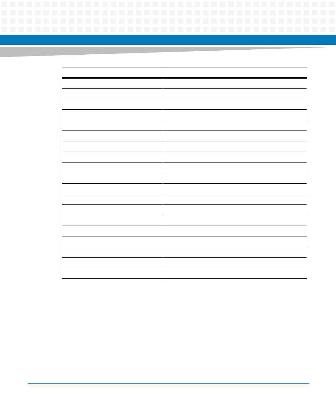
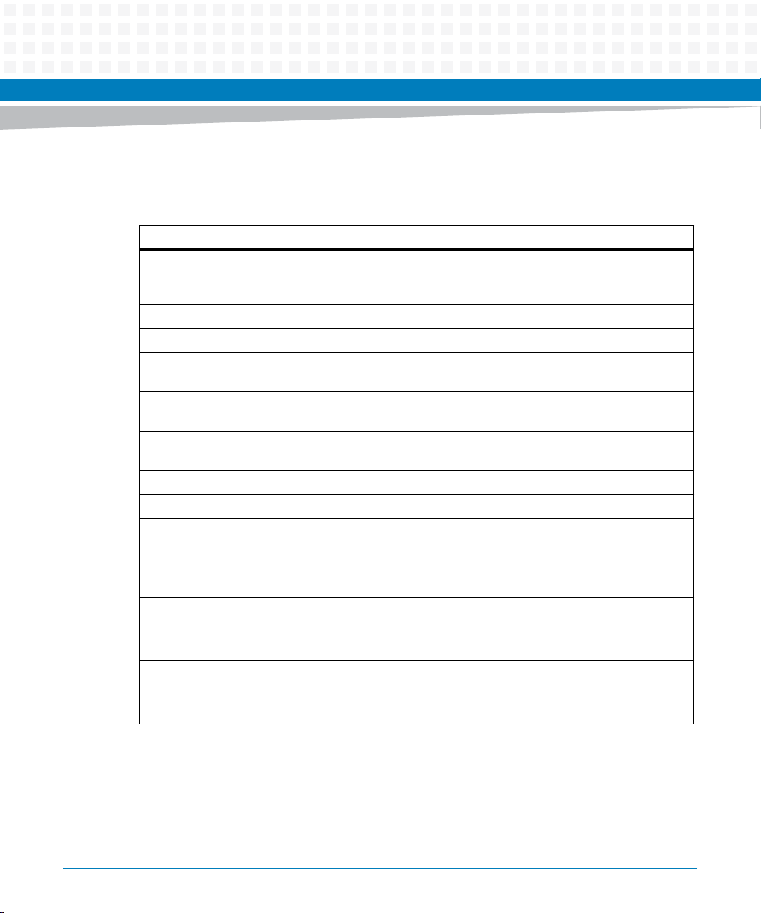
This Installation and Use manual is organized as follows:
Chapter Description
About this Manual Lists all conventions and abbreviations used in this manual and
Safety Notes Describes the safety information which has to be regarded
Sicherheitshinweise Translation of the chapter "Safety Information" to German
System Overview Provides an overview of the features of the system and lists order
Site Preparation Provides site planning considerations and checklists, describes the
System Installation Describes how to install and run the system
FRU Installation Describes how to install and replace blades, RTMs, shelf manager &
outlines the revision history
numbers
requirements and conditions
hub boards, power components, fan trays and air filters
Non-Field-Replaceable Units Describes the backplane, the alarm panel and the power inlet
Cooling Subsystem Contains information on fans and fan trays
Power Subsystem Contains information on power supplies and power distribution
Network Management and
System Access
DHCP Configuration and
Network Boot
Redundancy Contains information on cold standby, dual star network topology
Software Provides information that you need after you have successfully
Troubleshooting This chapter helps you to solve problems which may occur
Related Documentation Lists related documentation and specifications
Centellis 2000 Shelf Release 3.0 Installation and Use (6806800L99G)
Contains information on which component can be accessed via
which interface and information on the various addresses you need
to access system components
Contains information on preparing a TFTP server and a DHCP server
and describes how to boot the blades from a TFTP server via network
and actions of shelf manager and system manager during
switchover, takeover, failover, insertion, and extraction
installed the hardware
13
Page 14

About this Manual
Abbreviations
This document uses the following abbreviations:
Abbreviation Definition
AC Alternating Current
About this Manual
AdvancedTCA
ATC A
AMC AdvancedTCA Mezzanine Card
ANSI American National Standards Institute
ARP Address Resolution Protocol
AWG American Wire Gauge
BBS Basic Blade Services
CFM Cubic Feet per Minute
CGL Carrier Grade Linux
CISPR Comité International Spécial des Perturbations
CO Central Office
CPU Central Processing Unit
DC Direct Current
DHCP Dynamic Host Configuration Protocol
EMC Electromagnetic Compatibility
EMI Electromagnetic Interference
EMV Elektromagnetische Vertraeglichkeit
Advanced Telecom Computing Architecture
Radioélectriques
14
EN European Norm
ESD Electrostatic Discharge
ETSI European Telecommunication Standards Institute
FAE Field Application Engineers
FCC Federal Communications Commission
FCU Firmware Upgrade Utility
FRU Field Replaceable Unit
Centellis 2000 Shelf Release 3.0 Installation and Use (6806800L99G)
Page 15

About this Manual
Abbreviation Definition
FUMI Firmware Update Management Instrument
GmbH Gesellschaft mit beschraenkter Haftung
HA High Availability
HPI Hardware Platform Interface
HS Hot Swap
ID Identifier
IEC International Electric Code
IEEE Institute of Electrical and Electronics Engineers
I/O Input / Output
IP Internet Protocol
IPM Intelligent Platform Management
IPMB Intelligent Platform Management Bus
IPMC Intelligent Platform Management Controller
IPMI Intelligent Platform Management Interface
LED Light Emitting Diode
MMC Mezzanine Management Controller
NAE National Academy of Engineering
NEBS Network Equipment Building System
NEC National Electric Code
OEM Original Equipment Manufacturer
OOB Out-of-band
OS Operating System
PEM Power Entry Module
PCI Peripheral Component Interconnect
PICMG PCI Industrial Computer Manufacturers Group
PMC PCI Mezzanine Card
PSU Power Supply Unit
RAM Random Access Memory
Centellis 2000 Shelf Release 3.0 Installation and Use (6806800L99G)
15
Page 16
About this Manual
Abbreviation Definition
RMCP Remote Management Control Protocol
RoHS Restriction of Certain Hazardous Substances
ROM Read-Only Memory
RTM Rear Transition Module
SAF Service Availability Forum
SCSI Small Computer System Interface
SELV Safety Extra Low Voltage
SGA Shelf Geographical Address
ShM Shelf Manager
ShMC Shelf Management Controller
SSH Secure Shell
SW Ethernet Switch
About this Manual
16
TDM Time-Division Multiplexing
TPE Twisted-Pair Ethernet
UL Underwriters Laboratories
USB Universal Serial Bus
VCCI Voluntary Control Council for Interference
VLAN Virtual Local Area Network
WEEE Waste from Electrical and Electronic Equipment
Centellis 2000 Shelf Release 3.0 Installation and Use (6806800L99G)
Page 17
Conventions
The following table describes the conventions used throughout this manual.
Notation Description
0x00000000 Typical notation for hexadecimal numbers (digits are
0b0000 Same for binary numbers (digits are 0 and 1)
bold Used to emphasize a word
Screen Used for on-screen output and code related elements
Courier + Bold Used to characterize user input and to separate it
Reference Used for references and for table and figure
About this Manual
0 through F), for example used for addresses and
offsets
or commands in body text
from system output
descriptions
File > Exit Notation for selecting a submenu
<text> Notation for variables and keys
[text] Notation for software buttons to click on the screen
and parameter description
... Repeated item for example node 1, node 2, ..., node
12
.
.
.
.. Ranges, for example: 0..4 means one of the integers
| Logical OR
Centellis 2000 Shelf Release 3.0 Installation and Use (6806800L99G)
Omission of information from example/command
that is not necessary at the time being
0,1,2,3, and 4 (used in registers)
17
Page 18
About this Manual
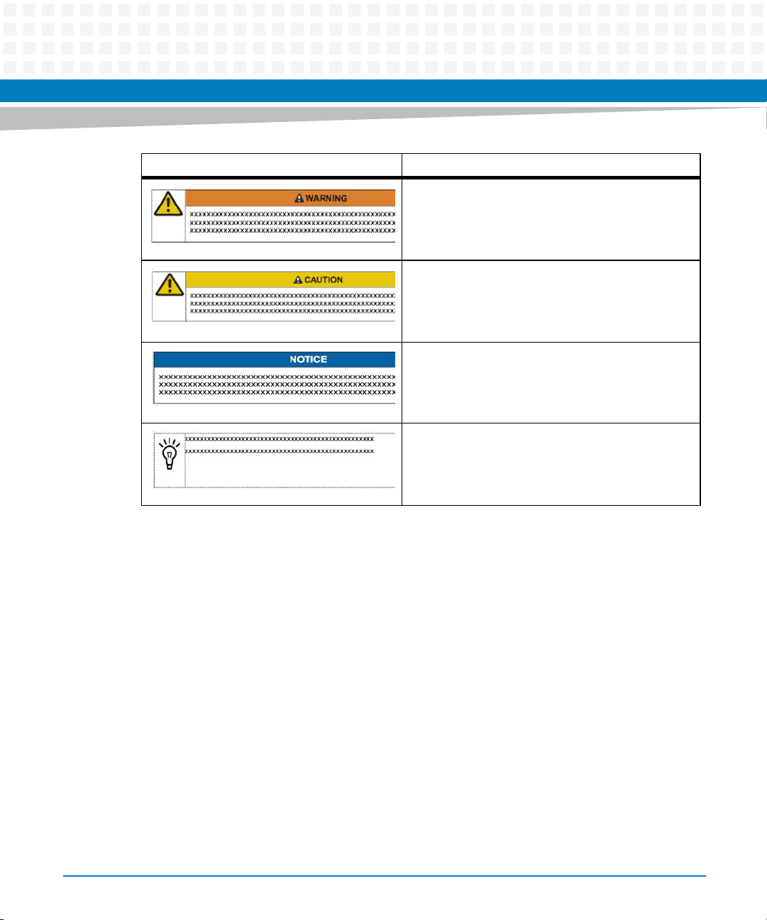
Notation Description
About this Manual
Indicates a hazardous situation which, if not avoided,
could result in death or serious injury
Indicates a hazardous situation which, if not avoided,
may result in minor or moderate injury
Indicates a property damage message
No danger encountered. Pay attention to important
information
18
Centellis 2000 Shelf Release 3.0 Installation and Use (6806800L99G)
Page 19

Summary of Changes
Order No. Date Description
6806800L99A July 2011 Initial Version
6806800L99B September 2011 Updated Table 1-2 on page 69, Figure 1-10 on page 67, and
6806800L99C March 2012 Added a Caution in User Card Slots on page 55.
About this Manual
Figure 1-11 on page 68. Updated sections DC System Startup
Procedure on page 93, Replacing DC Power Entry Modules on page
108, DC PEMs on page 30, and DC PEMs on page 44. Added
sections Installing Circuit Breaker Cover for DC PEMs on page 112
and Replacing the AC PSU Air Filter on page 128.
Added a Notice in System Installation on page 22 and
Systeminstallation on page 36.
Added sections Laser on page 33 and Laser on page 47.
Updated Standard Compliances on page 61, EMC on page 21 and
EMV on page 36.
6806800L99D April 2012 Deleted "Enclosed CD" section in Software Requirements on
page 177.
6806800L99E November 2012 Updated Table 8-1.
6806800L99F December 2012 Updated Standard Compliances on page 61.
6806800L99G May 2014 Rebranded to Artesyn.
Centellis 2000 Shelf Release 3.0 Installation and Use (6806800L99G)
19
Page 20

About this Manual
About this Manual
20
Centellis 2000 Shelf Release 3.0 Installation and Use (6806800L99G)
Page 21

Safety Notes
This section provides warnings that precede potentially dangerous procedures throughout
this manual. Instructions contained in the warnings must be followed during all phases of
operation, service, and repair of this equipment. You should also employ all other safety
precautions necessary for the operation of the equipment in your operating environment.
Failure to comply with these precautions or with specific warnings elsewhere in this manual
could result in personal injury or damage to the equipment.
Artesyn intends to provide all necessary information to install and handle the product in this
manual. Because of the complexity of this product and its various uses, we do not guarantee
that the given information is complete. If you need additional information, ask your Artesyn
Embedded Technologies representative.
The product has been designed to meet the standard industrial safety requirements. It must
only be used in its specific area of office telecommunication industry, industrial control, and
development. It must not be used in safety critical components, life supporting devices or on
aircraft.
Only personnel trained by Artesyn or persons qualified in electronics or electrical engineering
are authorized to install, remove or maintain the product. The information given in this manual
is meant to complete the knowledge of a specialist and must not be used as replacement for
qualified personnel.
Keep away from live circuits inside the equipment. Operating personnel must not remove
equipment covers. Only factory authorized service personnel or other qualified service
personnel may remove equipment covers for internal subassembly or component replacement
or any internal adjustment.
Do not install substitute parts or perform any unauthorized modification of the equipment or
the warranty may be voided. Contact your local Artesyn representative for service and repair
to make sure that all safety features are maintained.
EMC
The product has been tested and found to comply with the limits for a Class A digital device in
this system, pursuant to part 15 of the FCC Rules, EN 55022 Class A respectively. These limits
are designed to provide reasonable protection against harmful interference when the product
is operated in a commercial, business or industrial environment.
Centellis 2000 Shelf Release 3.0 Installation and Use (6806800L99G)
21
Page 22

The product generates and uses radio frequency energy and, if not installed properly and used
in accordance with this user's documentation, may cause harmful interference to radio
communications. Operating the product in a residential area is likely to cause harmful
interference, in which case the user will be required to correct the interference at his own
expense. To ensure proper EMC shielding, operate the system only with free slots populated
with filler blades.
To ensure EMC protection use only shielded cables when connecting peripherals to assure that
appropriate radio frequency emissions compliance is maintained. Installed blades must have
the face plates installed and all vacant slots in the shelf must be covered.
Grounding
If the product is not properly grounded, it may be damaged by electrostatic discharge.
Make sure that each of the system's parts contact the EMI gasket. The system contains gaskets
at the shelf and module level.
The shelf is also fitted with ESD snaps for the use with conductive wrist straps. Please take care
for proper ESD protection of the operator.
Safety Notes
This is a Class A product based on the standard of the Voluntary Control Council for
Interference by Information Technology Interference (VCCI). If this equipment is used in a
domestic environment, radio disturbance may arise. When such trouble occurs, the user may
be required to take corrective actions.
The equipment is suitable for installation in a Common Bonding Network (CBN) or Isolated
Bonding Network (IBN).
System Installation
System Damage
To avoid system damage verify that the system environment meets the environmental and
power requirements given in this manual before installing the system.
22
Centellis 2000 Shelf Release 3.0 Installation and Use (6806800L99G)
Page 23

Before you begin to set up and cable your new system, consider these guidelines:
Installation codes: This unit must be installed in accordance with the National Electrical
Code.
Overcurrent protection: A readily accessible listed branch circuit overcurrent protective
device must be incorporated into the building wiring. For appropriate AWG rating of the
overcurrent protection device see NEC Table 310.16 and other national regulations.
The protective bonding conductor depends on your power distribution topology. Make
sure that you use an appropriate protective bonding conductor regarding the rating of the
branch circuit protection.
Install the system safely. Make sure that cables and cords are out of the way.
Make sure that the set-up is comfortable for users.
System Damage
WARNING: The intra-building port(s) of the equipment or subassembly is suitable for
connection to intra-building or unexposed wiring or cabling only. The intra-building port(s) of
the equipment or subassembly MUST NOT be metallically connected to interfaces that
connect to the OSP or its wiring. These interfaces are designed for use as intra-building
interfaces only (Type 2 or Type 4 ports as described in GR-1089) and require isolation from the
exposed OSP cabling. The addition of Primary Protectors is not sufficient protection in order to
connect these interfaces metallically to OSP wiring.
Safety Notes
System Damage
Environmental contamination can impair system operation.
Locate the system in a stable area free of excess movement and jarring and free of dust, smoke,
and electrostatic discharge (ESD). Make sure that the temperature does not exceed the
operating temperature given in the environmental requirements in this manual and allow
room for proper air flow for cooling.
Personal Injury or System Damage (For AC)
The system is supplied by AC mains primary voltage. This voltage is considered hazardous.
Take appropriate precaution when cabling the system.
Centellis 2000 Shelf Release 3.0 Installation and Use (6806800L99G)
23
Page 24

Personal Injury or System Damage (For DC)
The system is supplied by a TNV-2 voltage. This voltage is considered hazardous. Make sure
that the power supply meets the relevant safety standards.
Ensure that TNV-2 is separated from dangerous voltages (mains) through double or reinforced
insulation.
Personal Injury or System Damage
A top-heavy rack can topple over, causing damage to equipment and injury to personnel.
If your system is the only one in the rack, make sure to mount the system in the lowest part of
the rack. If several systems are installed in one rack, start with the heaviest component at the
bottom. If the rack is equipped with stabilizing devices, make sure that they are installed and
extended so that the rack is secure. Then proceed to mount or service the system.
Personal Injury or System Damage
When pulling the system out of the rack, it can fall down and cause injuries.
Pull out the system cautiously.
Safety Notes
Personal Injury
The system is heavy and improper handling may lead to muscle strain or back injury.
Have two people lift the system or use lifting aids and proper lifting techniques when handling
the system. Do not use the FRU handles to lift the shelf.
System Damage
During the course of handling, shipping, and assembly, pins, mounting screws, fans and other
items can become loose or damaged.
Do not operate a damaged shelf, this can cause damage to devices that interfere with it.
Personal Injury
High leakage current can be hazardous and cause injury.
24
Centellis 2000 Shelf Release 3.0 Installation and Use (6806800L99G)
Page 25
Locate the caution label near the grounding studs (may vary from system to system) and make
an earth ground connection before connecting power to the PSU/PEM.
System Damage
Wrong jumper settings can make the shelf in-operable. Therefore, never change the settings
of the jumpers.
Blade and RTM Installation
Damage of Circuits
Electrostatic discharge and incorrect installation and removal of the product can damage
circuits or shorten their life.
Before touching the product make sure that your are working in an ESD-safe environment or
wear an ESD wrist strap or ESD shoes. Hold the product by its edges and do not touch any
components or circuits.
Safety Notes
Product Damage
If you install blades and RTMs in the wrong sequence, the blades and RTMs may be damaged.
First install the RTM, then install the matching blade.
Blade or System Damage
Installing a blade in the wrong slot may cause blade or system damage.
Only install blades in the designated slots.
Damage of RTM and Front Blade
Removing the RTM from the system while the payload of the front blade is powered up may
damage the front blade and RTM.
Whenever removing the RTM from the system, power down the payload of the front blade
first. This does not apply to hot-swap RTMs.
Centellis 2000 Shelf Release 3.0 Installation and Use (6806800L99G)
25
Page 26

RTM Malfunctioning
Incorrect RTM installation and removal can result in RTM malfunctioning.
When plugging the RTM in or removing it, do not press on the face plate but use the handles.
RTM Damage
Installing the RTM with other blades than the ones designed for it may damage the RTM and
the front blade.
Only install the RTM with the correct front blade.
Data Loss
Removing the RTM with the system power on and the blue LED on the front blade still flashing
causes data loss.
Before removing the RTM from a powered system, power down the slot by opening the right
handle of the front blade and wait until the blue LED is permanently on.
Safety Notes
Blade Malfunctioning
Incorrect blade installation and removal can result in blade malfunctioning.
Make sure that the blade is connected to the system backplane via all assembled connectors
and that power is available on all zone 1 power pins.
Operation
System Overheating
Cooling Vents
Improper cooling can lead to blade and system damage and may void the manufacturer’s
warranty.
To ensure proper cooling and undisturbed airflow through the system always operate the
system in a horizontal position. Do not obstruct the ventilation openings at the front and rear
of the system. Keep the fresh air intake at the bottom-front side of the chassis completely clear.
Make sure that the fresh air supply is not mixed with hot exhaust from other devices. Make sure
that all slots are populated with either blades, filler blades, or dummy blades.
26
Centellis 2000 Shelf Release 3.0 Installation and Use (6806800L99G)
Page 27

Product Damage
High humidity and condensation on blade surfaces causes short circuits.
Do not operate the system outside the specified environmental limits. Make sure the system is
completely dry and there is no moisture on any surface before applying power. Do not start the
system below 0 ºC.
Injury
Caution: This unit has two AC power connections/ two -48 V to -60 VDC feeds. All must be
disconnected to de energize the system. To reduce the risk of injury, disconnect the feeds
when removing power from the system.
System Damage
Air Filters
Air contamination can pollute the air filter and obstruct the air intake of the system which may
cause system overheating and component damage.
To guarantee proper airflow through the system the air filters have to be replaced at least every
six months. Artesyn recommends to replace the air filters every 90 days. Filter replacement
frequency depends on the environment the system is subjected to.
Because central offices vary in physical location and cleanliness, check your air filters every
week after you first install your system. In a dusty environment, filter replacement may be
required more often than in a cleaner environment. Check the filters frequently until you have
a good idea of how often they must be replaced. Based on your findings, establish a regular
replacement schedule and keep a log to record the date of each filter replacement.
Safety Notes
Filter Frames
Wrong insertion may damage the frame or the guides.
When inserting the filter frame into the shelf, pay attention to insert the appropriate bottom
or top frame and to align it accurately to the guides.
Centellis 2000 Shelf Release 3.0 Installation and Use (6806800L99G)
27
Page 28

Safety Notes
This equipment is designed to permit the connection of the earthed conductor of the DC
supply circuit to the earthing conductor at the equipment. If this connection is made, all of the
following conditions must be met:
This equipment shall be connected directly to the DC supply system earthing electrode
conductor or to a bonding jumper from an earthing terminal bar or bus to which the DC
supply system earthing electrode conductor is connected.
This equipment shall be located in the same immediate area (such as, adjacent cabinets)
as any other equipment that has a connection between the earthed conductor of the same
DC supply circuit and the earthing conductor, and also the point of earthing of the DC
system. The DC system shall not be earthed elsewhere.
The DC supply source shall be located within the same premises as this equipment.
Switching or disconnecting devices shall not be in the earthed circuit conductor between
the DC source and the point of connection of the earthing electrode conductor.
French translation: Cet appareil est conçu pour permettre le raccordement du conducteur relié
à la terre du circuit d'alimentation c.c. au conducteur de terre de l'appareil. Pour ce
raccordement, toutes les conditions suivantes doivent être respectées:
Ce matériel doit être raccordé directement au conducteur de la prise de terre du circuit
d'alimentation c.c. ou à une tresse de mise à la masse reliée à une barre omnibus de terre
laquelle est raccordée à l'électrode de terre du circuit d'alimentation c.c.
Les appareils dont les conducteurs de terre respectifs sont raccordés au conducteur de
terre du même circuit d'alimentation c.c. doivent être installés à proximité les uns des
autres (p.ex., dans des armoires adjacentes) et à proximité de la prise de terre du circuit
d'alimentation c.c. Le circuit d'alimentation c.c. ne doit comporter aucune autre prise de
terre.
La source d'alimentation du circuit c.c. doit être située dans la même pièce que le matériel.
- Il ne doit y avoir aucun dispositif de commutation ou de sectionnement entre le point de
raccordement au conducteur de la source d'alimentation c.c. et le point de raccordement
à la prise de terre.
System Overheating
If you reduce the blower speed via HPI the system temperature will rise.
28
Centellis 2000 Shelf Release 3.0 Installation and Use (6806800L99G)
Page 29

Constantly control the system temperature once you have reduced the blower speed.
While operating the system ensure that the environmental and power requirements are met.
Injuries or Short Circuits
Blade or Power Supply
In case the ORing diodes of the blade fail, the blade may trigger a short circuit between input
line A and input line B so that line A remains powered even if it is disconnected from the power
supply circuit (and vice versa).
To avoid damage or injuries, always check that there is no more voltage on the line that has
been disconnected before continuing your work.
System Expansion
System Overload
To avoid an overload of the system check the total power consumption of all components
installed (see the technical specification of the respective components). Ensure that any
individual output current of any source stays within its acceptable limits (see the technical
specification of the respective source).
Safety Notes
Loss of Safety Compliance
Using of Additional Plug-in Blades
By using additional plug-in blades it may be possible that the system may become incompliant.
The system integrator has to ensure that the compliancy is guaranteed.
Power Feed
Personal Injury
Touching the power input terminals with metallic objects on your hands, wrists, or hanging
from your neck may lead to severe injuries through electric shock and burning.
Do not wear any metallic attire or commodity on your hands, wrists, or hanging from your
neck when working at the power input terminals or power input cables. Be extremely careful
when you use electrically conductive tools near the PSUs/PEMs.
Centellis 2000 Shelf Release 3.0 Installation and Use (6806800L99G)
29
Page 30

Short Circuits or Personal Injury
Ensure that the power feeds you plan to remove or attach are powered off and cannot be
switched on while you are working.
Ensure that all power input lines are not energized. Be careful with the used tools in order to
prevent a short circuit.
Product Damage
Improper cabling damages your product.
Take extreme care not to connect the power cable in reverse polarity.
AC PSUs
Personal Injury
Hot PSUs may cause injury.
Allow the PSU to cool before servicing.
Safety Notes
DC PEMs
Personal Injury
Hot PEMs may cause injury.
Allow the PEM to cool before servicing.
System Damage
Applying feed power to the PEM with the PEM breaker in the ON position damages your system
and/or system components.
The PEM breaker must be in the OFF position when you turn on the feed power.
System Damage
Inserting or extracting the PEM with the PEM breaker in the ON position may damage your
system.
If power is connected to the shelf, make sure the PEM breaker is in the OFF position before you
insert or extract a PEM.
30
Centellis 2000 Shelf Release 3.0 Installation and Use (6806800L99G)
Page 31

PEM Damage
Placing the PEM circuit breaker to the ON position while there is a permanent short circuit in
the system may lead to PEM damage.
Make sure that there is no shortage in the system.
Fan Trays
System Damage
Insufficient cooling may damage the system.
The cooling system is designed to provide sufficient cooling with a single fan tray at work.
However, under bad conditions or due to a failure of the remaining fans, the cooling capacity
of a single fan tray may not suffice.
Avoid delays during fan replacement.
Safety Notes
Fan Damage
When a fan tray is taken out of operation or is removed during a replacement procedure, the
system manager will compensate for the loss by increasing the speed of the remaining fans.
Turning on high speed for a long time may shorten the life of the fans and may exceed
allowable acoustic noise limits.
Replace the fan tray without delays.
System Damage
Removing the single operating fan tray will lead to overheating very quickly.
Make sure that there is always one operating fan tray present in the system.
Personal Injury
Rotating Fans
Inserting tools or fingers into operational fans may cause injuries.
Keep clear of the fans as long as they are rotating.
Centellis 2000 Shelf Release 3.0 Installation and Use (6806800L99G)
31
Page 32

Shelf Manager and Hub Board
Data Loss
Removing the product with the blue LED still blinking may result in data loss. Wait until the
blue LED is permanently illuminated before removing the board.
Cabling
Personal Injury
The cabling should follow existing cable paths using existing or similar cable fastenings.
Never change the system's cabling as delivered by Artesyn. Check proper function of the
system after cabling extensions. To avoid injuries always ensure that cables are securely
installed so that nobody can trip over them.
Safety Notes
Personal Injury through Electric Shock
Touching contacts and cables during system operation can cause injuries through electric
shock.
To avoid electric shock make sure that contacts and cables of the system cannot be touched
while the system is operating. If in doubt concerning cabling, ask your local Artesyn
representative.
Cable Damage
Folding the fiber cable damages the cable and inhibits the data transmission. Therefore, make
sure you do not fold the cable.
32
Centellis 2000 Shelf Release 3.0 Installation and Use (6806800L99G)
Page 33

RJ-45 Connector
System Damage
RJ-45 connectors on blades are either twisted-pair Ethernet (TPE) or E1/T1/J1 network
interfaces. Connecting an E1/T1/J1 line to an Ethernet connector may damage your system.
Make sure that TPE connectors near your working area are clearly marked as network
connectors.
Verify that the length of an electric Ethernet cable connected to a RJ-45 TPE bushing does
not exceed 100 m.
Make sure the TPE bushing of the system is connected only to safety extra low voltage
circuits (SELV circuits).
If in doubt, ask your system administrator.
Safety Notes
For more information, see the documentation of the respective blade.
Laser
Personal Injury
If a label with the words CLASS 1 LASER PRODUCT is affixed to the back of your system, the unit
is equipped with a laser device. These devices contain a laser diode that produces invisible laser
radiation harmful to the eyes.
Performing adjustments or procedures other than those specified in this manual may result in
hazardous radiation exposure. Do not look into the optical lens at any time.
Environment
Environmental Damage
Improperly disposing of used products may harm the environment.
Always dispose of used products according to your country’s legislation and manufacturer’s
instructions.
Centellis 2000 Shelf Release 3.0 Installation and Use (6806800L99G)
33
Page 34

Safety Notes
34
Centellis 2000 Shelf Release 3.0 Installation and Use (6806800L99G)
Page 35

Sicherheitshinweise
Dieses Kapitel enthält Hinweise, die potentiell gefährlichen Prozeduren innerhalb dieses
Handbuchs vorrangestellt sind. Beachten Sie unbedingt in allen Phasen des Betriebs, der
Wartung und der Reparatur des Systems die Anweisungen, die diesen Hinweisen enthalten
sind. Sie sollten außerdem alle anderen Vorsichtsmaßnahmen treffen, die für den Betrieb des
Systems innerhalb Ihrer Betriebsumgebung notwendig sind. Wenn Sie diese
Vorsichtsmaßnahmen oder Sicherheitshinweise, die an anderer Stelle diese Handbuchs
enthalten sind, nicht beachten, kann das Verletzungen oder Schäden am System zur Folge
haben.
Artesyn ist darauf bedacht, alle notwendigen Informationen zum Einbau und zum Umgang mit
dem System in diesem Handbuch bereit zu stellen. Da es sich jedoch bei dem System um ein
komplexes Produkt mit vielfältigen Einsatzmöglichkeiten handelt, können wir die
Vollständigkeit der im Handbuch enthaltenen Informationen nicht garantieren. Falls Sie
weitere Informationen benötigen sollten, wenden Sie sich bitte an die für Sie zuständige
Geschäftsstelle von Artesyn.
Das System erfüllt die für die Industrie geforderten Sicherheitsvorschriften und darf
ausschließlich für Anwendungen in der Telekommunikationsindustrie, im Zusammenhang mit
Industriesteuerungen und in der Entwicklung verwendet werden. Es darf nicht in
sicherheitskritischen Anwendungen, lebenserhaltenden Geräten oder in Flugzeugen
verwendet werden.
Einbau, Wartung und Betrieb dürfen nur von durch Artesyn ausgebildetem oder im Bereich
Elektronik oder Elektrotechnik qualifiziertem Personal durchgeführt werden. Die in diesem
Handbuch enthaltenen Informationen dienen ausschließlich dazu, das Wissen von
Fachpersonal zu ergänzen, können dieses jedoch nicht ersetzen.
Halten Sie sich von stromführenden Leitungen innerhalb des Systems fern. Entfernen Sie auf
keinen Fall die Systemabdeckung. Nur werksseitig zugelassenes Wartungspersonal oder
anderweitig qualifiziertes Wartungspersonal darf die Systemabdeckung entfernen, um
Systemkomponenten zu ersetzen oder andere Anpassungen vorzunehmen.
Installieren Sie keine Ersatzteile oder führen Sie keine unerlaubten Veränderungen am System
durch, sonst verfällt die Garantie. Wenden Sie sich für Wartung oder Reparatur bitte an die für
Sie zuständige Geschäftsstelle von Artesyn. So stellen Sie sicher, dass alle
sicherheitsrelevanten Aspekte beachtet werden.
Centellis 2000 Shelf Release 3.0 Installation and Use (6806800L99G)
35
Page 36

EMV
Sicherheitshinweise
Das Produkt wurde getestet und erfüllt die für digitale Geräte der Klasse A gültigen Grenzwerte
gemäß den FCC-Richtlinien Abschnitt 15 bzw. EN 55022 Klasse A. Diese Grenzwerte sollen
einen angemessenen Schutz vor Störstrahlung beim Betrieb des Produkts in Geschäfts-,
Gewerbe- sowie Industriebereichen gewährleisten.
Das Produkt arbeitet im Hochfrequenzbereich und erzeugt Störstrahlung. Bei
unsachgemäßem Einbau und anderem als in diesem Handbuch beschriebenen Betrieb können
Störungen im Hochfrequenzbereich auftreten. Freie Steckplätze müssen mit PlatzhalterBoards belegt werden, um sicherzustellen, dass die EMV-Richtlinien erfüllt werden.
Benutzen Sie zum Anschließen von Peripheriegeräten ausschließlich abgeschirmte Kabel. So
stellen Sie sicher, dass ausreichend Schutz vor Störstrahlung vorhanden ist. Die Blades müssen
mit der Frontblende installiert und alle freien Steckplätze müssen mit Blindblenden abgedeckt
sein.
Erdung
Wenn das Produkt nicht richtig geerdet ist, kann es es durch elektrostatische Entladungen
beschädigt werden.
Stellen Sie sicher, dass alle Systemteile die EMI-Dichtung berühren. Die Dichtungen befinden
sich sowohl am System als auch an den einzelnen Modulen.
Am System befinden sich auch ESD-Kontakte. Stellen Sie sicher, dass jede Person, die mit dem
System arbeitet, mit ESD-Schutz, zum Beispiel ESD-Bändern, arbeitet.
Dies ist eine Einrichtung der Klasse A. Diese Einrichtung kann im Wohnbereich Funkstörungen
verursachen; in diesem Fall kann vom Betreiber verlangt werden, angemessene Maßnahmen
durchzuführen und dafür aufzukommen.
Das Produkt ist für den Einsatz in Netzwerken mit gemeinsamem Potentialausgleich oder mit
isoliertem Potentialausgleich geeignet.
Systeminstallation
Beschädigung des Systems
Bevor Sie das System installieren, überprüfen Sie, ob die im Handbuch beschriebenen
Anforderungen erfüllt werden.
36
Centellis 2000 Shelf Release 3.0 Installation and Use (6806800L99G)
Page 37

Sicherheitshinweise
Beachten Sie folgende allgemeinen Sicherheitshinweise vor der Installation und Verkabelung
des Systems:
Installationsrichtlinien: Dieses System muss gemäß folgender Richtlinien installiert
werden: National Electrical Code.
Überstrom-Schutzeinrichtung: Eine leicht zugängliche Trennvorrichtung muss in der
Gebäudeverkabelung eingebaut sein. Einen angemessenen AWG (American Wire Gauge amerikanische Norm für Drahtquerschnitte)-Wert der Überstrom-Schutzeinrichtung
können Sie der NEC (National Electrical Code) Tabelle 310.16 oder anderen nationalen
Regelwerken entnehmen.
Der Erdungsleiter ist abhängig von der Spannungsverteilungstopologie innerhalb Ihrer
Anlage. Stellen Sie sicher, dass Sie einen angemessenen Erdungsleiter gemäß der
Auslegung des Zugangsleitungsschutzes verwenden.
Bauen Sie das System sicher ein. Stellen Sie sicher, dass Kabel und Leitungen nicht im Weg
sind.
Stellen Sie sicher, dass der Systemaufbau anwenderfreundlich ist.
Beschädigung des Systems
Die Gebäude-internen Schnittstellen ("intra-building ports" per GR-1089-CORE) der Geräte
oder Baugruppen sind nur für gebäudeinterne Verkabelung vorgesehen. Die Schnittstellen
sind als Typ 2 oder Typ 4 definiert (wie in GR-1089-Core beschrieben) und erfordern eine
Isolation zu Leitungen außerhalb des Gebäudes.
Die Gebäude-internen Schnittstellen dürfen keine elektrisch leitende Verbindung zu Leitungen
außerhalb des Gebäudes haben. Ein "Primary Protector" (wie in GR-1089-CORE beschrieben)
ist keine ausreichende Absicherung, um die Gebäude-internen Schnittstellen mit Leitungen
außerhalb des Gebäudes zu verbinden.
Beschädigung des Systems
Verschmutzungen können das System beschädigen.
Betreiben Sie das System an einem erschütterungsfreien Ort, an dem weder Staub, Rauch noch
elektrostatische Entladungen auftreten. Stellen Sie außerdem sicher, dass die klimatischen
Bedingungen, die in diesem Handbuch spezifiziert sind, eingehalten werden und genug Raum
für die Luftzirkulation vorhanden ist.
Centellis 2000 Shelf Release 3.0 Installation and Use (6806800L99G)
37
Page 38

Verletzungsgefahr und Beschädigung des Systems
(AC)
Das System wird durch die Netzspannung (100V bis 240VAC) versorgt. Diese Spannung kann
gefährlich sein. Treffen sie entsprechende Vorsichtsmaßnahmen, wenn sie an der Verkabelung
des Systems arbeiten.
Verletzungsgefahr und Beschädigung des Systems (DC)
Das System ist an eine TNV-2-Spannungsquelle angeschlossen. Diese Spannung kann
gefährlich sein.
Stellen Sie sicher, dass die externe Spannungsversorgung den entsprechenden
Sicherheitsstandards entspricht.
Stellen Sie sicher, dass die TNV-2-Spannungsversorgung von gefährlicheren Spannungsquellen
(Hauptstromversorgung) durch doppelte oder verstärkte Isolierung getrennt ist.
Sicherheitshinweise
Verletzungsgefahr und Beschädigung des Systems
Wenn die Gewichte im Schaltschrank ungleich verteilt sind, kann der Schaltschrank umkippen
und dadurch die Einrichtungen beschädigen oder Personen verletzen.
Bauen Sie das System deshalb ganz unten im Schrank ein, wenn es das einzige System im
Schrank ist. Wenn mehrere Systeme in einen Schrank eingebaut werden sollen, platzieren Sie
das schwerste System ganz unten und die leichteren weiter oben. Falls der Schaltschrank mit
Kippsicherungen ausgestattet ist, stellen Sie sicher, dass diese auch installiert und ausgefahren
sind, um einen sicheren Stand des Schranks zu gewährleisten. Beginnen Sie erst danach mit
dem Einbau oder der Wartung des Systems.
Verletzungsgefahr oder Beschädigung des Systems
Das System kann beim Herausziehen herunterfallen und Verletzungen verursachen.
Ziehen Sie das System vorsichtig heraus, damit es nicht herunterfällt.
Verletzungsgefahr
Das System ist schwer, und eine unangemessene Handhabung kann zu Zerrungen oder
Rückenschäden führen. Heben Sie deshalb das System nur zu zweit oder benutzen Sie
zusätzliche Hilfsmittel. Verwenden Sie zum Heben des Systems nicht die Griffe der
eingebauten Module.
38
Centellis 2000 Shelf Release 3.0 Installation and Use (6806800L99G)
Page 39

Beschädigung des Systems
Während des Transportes und Zusammenbaus des Systems können sich Teile, wie zum
Beispiel Schrauben, Stecker oder Lüfter, lösen oder beschädigt werden.
Nehmen Sie das System nicht in Betrieb, wenn Teile beschädigt sind. Dies könnte zu
Beschädigungen an anderen Teilen führen.
Verletzungsgefahr
Hoher Ableitstrom kann gefährlich sein und Verletzungen verursachen.
Stellen Sie fest, wo sich der Aufkleber mit dem Gefahrenzeichen und die zugehörigen
Schuzleiter befinden (die Position kann sich bei verschiedenen Systemen unterscheiden).
Stellen Sie vor Anschluss des Systems an den Versorgungsstromkreis unbedingt eine
Erdungsverbindung her.
Sicherheitshinweise
Beschädigung des Systems
Falsche Jumper-Einstellungen können dazu führen, dass das System nicht mehr funktioniert.
Ändern Sie deshalb nie die Einstellungen der Jumper.
Board und RTM Installation
Produktschaden
Berühren Sie das Board oder elektrische Komponenten ohne ausreichenden ESD-Schutz, kann
dies zu einer Beschädigung des Boards führen.
Bevor Sie Boards berühren, vergewissern Sie sich, dass Sie in einem ESD-geschützten Bereich
arbeiten, oder tragen Sie ein ESD-Handgelenkband oder ESD-Schuhe. Fassen Sie Boards nur an
der Seite an und berühren Sie keine elektronischen Komponenten.
Produktschaden
Wenn Sie RTMs und AdvancedTCA Boards in der falschen Reihenfolge installieren, können die
RTMs und AdvancedTCA Boards beschädigt werden.
Installieren Sie zuerst das RTM und erst danach das passende AdvancedTCA Board.
Centellis 2000 Shelf Release 3.0 Installation and Use (6806800L99G)
39
Page 40

Beschädigung des Boards oder Systems
Wird ein Board in den falschen Steckplatz im System gesteckt, können sowohl das Board als
auch das System beschädigt werden. Installieren Sie Boards deshalb ausschließlich in dafür
vorgesehene Steckplätze.
Beschädigung des RTMs oder Boards
Wird das RTM ausgebaut, während die Payload des dazugehörigen AdvancedTCA Boards noch
nicht heruntergefahren ist, kann dies zu Beschädigungen am Board oder RTM führen.
Fahren Sie deshalb die Payload des AdvancedTCA Boards immer herunter, bevor Sie das
dazugehörige RTM aus dem System entfernen. Dies gilt nicht für RTMs, die hot-swap-fähig
sind.
Beschädigung des RTMs
Fehlerhafte Installation kann zu einer Beschädigung des RTMs führen. Verwenden Sie die
Handles, um das RTM zu installieren/deinstallieren. Auf diese Weise vermeiden Sie, dass die
Frontblende oder die Platine deformiert oder zerstört wird.
Sicherheitshinweise
Beschädigung des RTMs oder Boards
Das System wird beschädigt, wenn die RTMs nicht zu den von vorn in dem System installierten
Boards passen.
Stellen Sie deshalb sicher, dass Boards und RTMs, die von vorn bzw. von hinten in den gleichen
Steckplatz des Systems eingebaut werden, stets zueinander passen.
Datenverlust
Das Entfernen eines RTMs während des Systembetriebs und blinkender blauer LED des FrontBoards führt zu Datenverlust.
Vor dem Entfernen des RTMs im laufenden Systembetrieb schalten Sie das entsprechende
Board ab, indem Sie die Griffe des Boards öffnen. Warten Sie, bis die blaue LED dauerhaft
leuchtet.
Fehlfunktion
Unsachgemäßer Ein- und Ausbau von Boards kann zu einer Fehlfunktion des Boards führen.
Vergewissern Sie sich, dass das Board über alle Stecker an die AdvancedTCA-Backplane
angeschlossen und die Stromversorgung gewährleistet ist.
40
Centellis 2000 Shelf Release 3.0 Installation and Use (6806800L99G)
Page 41

Betrieb
Überhitzung des Systems
Lüftungsschlitze
Unzureichende Lüftung kann Schäden an Boards und am System verursachen und den Verlust
der Garantie zur Folge haben.
Um eine ausreichende Lüftung zu gewährleisten, stellen Sie sicher, dass das System während
des Betriebs stets waagerecht steht. Halten Sie die Lüftungsschlitze an der Vorder- und
Rückseite des Systems frei. Halten Sie die Frischluftzufuhröffnung an der Vorderseite des
Systems völlig frei und stellen Sie sicher, dass sich die Frischluft nicht mit der Abluft von
anderen Systemen mischt. Um eine ungestörte Luftzirkulation zu gewährleisten, stellen Sie
sicher, dass alle Steckplätze mit Boards oder Platzhaltern belegt sind.
Beschädigung des Systems
Durch hohe Luftfeuchtigkeit können Kurzschlüsse entstehen.
Betreiben Sie das System nur innerhalb der angegebenen Grenzwerte für die relative
Luftfeuchtigkeit und Temperatur. Stellen Sie vor dem Einschalten des Stroms sicher, dass sich
auf dem System und auf den Boards kein Kondensat befindet und starten Sie das System nicht
unter 0ºC.
Sicherheitshinweise
Stromschlaggefahr
Das System besitzt zwei Anschlüsse für die Netzspannung (100V bis 240VAC)/ zwei Anschlüsse
für -48 V bis -60 VDC. Alle Anschlüsse müssen vom System entfernt werden, um das System
spannungsfrei zu schalten.
Um eine Verletzungsgefahr zu minimieren, entfernen Sie die Anschlüsse, wenn Sie das System
ausschalten.
Beschädigung des Systems
Luftfilter
Verunreinigungen in der Luft können den Luftfilter verschmutzen und so die Luftzufuhr des
Systems beeinträchtigen. Das kann zur Überhitzung des Systems und zu Schäden an
Systemteilen führen.
Centellis 2000 Shelf Release 3.0 Installation and Use (6806800L99G)
41
Page 42

Um einen reibungslosen Luftstrom durch das System zu gewährleisten, sollten Sie die Luftfilter
spätestens alle sechs Monate austauschen. Artesyn empfiehlt, die Filter alle 90 Tage
auszutauschen. Wie häufig Sie die Filter austauschen müssen, hängt von der Umgebung ab, in
der das System betrieben wird.
Luftfilter sollten mindestens alle 90 Tage ausgewechselt werden. Je nach
Umgebungsbedingen kann dies auch früher nötig sein. Da die Verhältnisse in
Vermittlungsstellen sehr unterschiedlich sein können, sollten Sie die Luftfilter nach der
Erstinstallation des Systems jede Woche kontrollieren. In einer staubigen Umgebung muss ein
Filter gegebenenfalls öfter ausgetauscht werden als in einer sauberen Umgebung. Prüfen Sie
die Filter regelmäßig, bis Sie eine Vorstellung davon haben, wie oft die Filter ausgetauscht
werden müssen. Erstellen Sie aufgrund Ihrer Beobachtungen einen Plan für den Austausch und
protokollieren Sie jeden Austausch des Filters.
Filterrahmen
Wenn Sie einen Rahmen falsch einbauen, kann dies den Rahmen oder die Führungsschienen
beschädigen.
Wenn Sie einen Rahmen in das Gehäuse einführen, achten Sie darauf, dass es sich um den
passenden unteren oder oberen Rahmen handelt und dass sich der Rahmen richtig in der
Führung befindet.
Sicherheitshinweise
Überhitzung des Systems
Wenn Sie die Geschwindigkeit der Lüfter über HPI reduzieren, steigt die Systemtemperatur an.
Kontrollieren Sie deshalb ständig die Temperatur im System, wenn Sie die Geschwindigkeit der
Lüfter reduziert haben. Stellen Sie während des Betriebs sicher, dass die Bedingungen, die im
Handbuch beschrieben sind, eingehalten werden.
Verletzungen oder Kurzschlüsse
Blade oder Stromversorgung
Falls die ORing-Dioden des Blades durchbrennen, kann das Blade einen Kurzschluss zwischen
den Eingangsleitungen A und B verursachen. In diesem Fall ist Leitung A immer noch unter
Spannung, auch wenn sie vom Versorgungskreislauf getrennt ist (und umgekehrt).
Prüfen Sie deshalb immer, ob die Leitung spannungsfrei ist, bevor Sie Ihre Arbeit fortsetzen,
um Schäden oder Verletzungen zu vermeiden.
42
Centellis 2000 Shelf Release 3.0 Installation and Use (6806800L99G)
Page 43

Systemerweiterung
Systemüberlastung
Verhindern Sie eine Systemüberlastung, indem Sie die gesamte aufgenomme Leistung aller
eingebauten Komponenten, also z.B. der installierten Boards und Laufwerke (siehe die
technischen Daten der entsprechenden Komponente) überprüfen. Bei Ihrem System darf die
Gesamtleistung die im Abschnitt Power Requirements definierten Werte nicht überschreiten.
Verlust der Sicherheitszulassung
Verwendung zusätzlicher Module
Wenn Sie zusätzliche Module und Boards verwenden, ist es möglich, dass das System nicht
mehr den gültigen Sicherheits- und EMV-Normen entspricht. Der Systemintegrator muss die
Einhaltung der gültigen Normen sicherstellen.
Sicherheitshinweise
Stromzufuhr
Verletzungsgefahr
Berühren metallische Gegenstände an Händen, Handgelenken oder am Hals die InputTerminals, kann dies zu schweren Verletzungen durch Stromschlag oder Verbrennungen
führen. Tragen Sie bei der Arbeit mit dem System keine metallischen Gegenstände an Ihren
Händen oder Armen und lassen sie keine metallischen Gegenstände um Ihren Hals hängen.
Seien Sie extrem vorsichtig mit elektrisch leitenden Gegenständen in der Nähe der PSUs/PEMs.
Kurzschluss und Gefahr durch Stromschlag
Um einen elektrischen Schlag zu vermeiden, überzeugen Sie sich, dass vor dem Berühren der
Input-Terminals die Stromzufuhr unterbrochen ist und während der Arbeit unterbrochen
bleibt. Vermeiden Sie Kurzschlüsse, indem Sie sehr vorsichtig mit dem Werkzeug umgehen.
Beschädigung des Systems
Falscher Anschluss von Stromkabeln beschädigt das System.
Achten Sie darauf, dass Sie das Stromkabel mit der richtigen Polarität anschließen.
Centellis 2000 Shelf Release 3.0 Installation and Use (6806800L99G)
43
Page 44

AC PSUs
Verletzungsgefahr
Das Berühren einer heißen Spannungsversorgungseinheit (PSU) kann zu Verletzungen führen.
Lassen Sie sie abkühlen, bevor Sie sie mit bloßen Händen herausziehen.
DC PEMs
Verletzungsgefahr
Das Berühren einer heißen Spannungsversorgungseinheit (PEM) kann zu Verletzungen führen.
Lassen Sie sie abkühlen, bevor Sie sie mit bloßen Händen herausziehen.
Beschädigung des Systems
Wenn sich beim Einschalten der Stromversorgung der Trennschalter einer
Spannungsversorgungseinheit (PEM) in der Stellung ON befindet, kann dies Ihr System
und/oder Systemkomponenten beschädigen.
Wenn Sie den Strom einschalten, müssen sich die Trennschalter der
Spannungsversorgungseinheiten in der Stellung OFF befinden.
Sicherheitshinweise
Beschädigung des Systems
Wenn Sie eine Spannungsversorgungseinheit (PEM) aus dem System ausbauen oder in das
System installieren, während der Trennschalter auf ON steht, kann dies Ihr System
beschädigen.
Wenn das System mit Strom versorgt wird, stellen Sie sicher, dass sich der Trennschalter der
Spannungsversorgungseinheit in der Position OFF befindet, bevor Sie die
Spannungsversorgungseinheit installieren oder ausbauen.
Beschädigung der Spannungsversorgungseinheit
Wenn Sie den Trennschalter einer Spannungsversorgungseinheit (PEM) auf ON stellen,
während ein Kurzschluss im System vorliegt, kann dies das PEM beschädigen.
Stellen Sie deshalb sicher, dass kein Kurzschluss im System vorliegt.
44
Centellis 2000 Shelf Release 3.0 Installation and Use (6806800L99G)
Page 45

Lüftermodule
Beschädigung des Systems
Unzureichende Kühlung kann das System beschädigen.
Das Lüftungssystem ist so ausgelegt, dass ein einzelnes funktionierendes Lüftermodul für
ausreichende Lüftung sorgt. Unter ungünstigen Umständen oder bei einer Fehlfunktion der
verbleibenden Lüfter reicht die Lüftungsleistung eines einzelnen Lüftermoduls aber
möglicherweise nicht aus. Nehmen Sie deshalb den Austausch ohne Verzögerung vor.
Beschädigung von Lüftern
Wenn ein Lüfter außer Betrieb ist oder während einer Austauschprozedur aus dem System
entfernt wird, veranlasst der System-Manager die übrigen Lüfter dazu, mit höherer
Geschwindigkeit zu drehen. Wenn Lüfter über einen längeren Zeitraum mit hoher
Geschwindigkeit laufen, kann das ihre Lebenszeit verkürzen und die zulässigen
Lärmgrenzwerte übersteigen.
Tauschen Sie das Lüftermodul ohne Verzögerung aus.
Sicherheitshinweise
Beschädigung des Systems
Wenn Sie das einzige funktionierende Lüftermodul entfernen, kommt es in sehr kurzer Zeit zu
einer Überhitzung.
Stellen Sie sicher, dass sich immer mindestens ein funktionierendes Lüftermodul im System
befindet.
Verletzungsgefahr
Rotierende Lüfterschaufeln
Sie können verletzt werden, wenn Sie Werkzeuge oder Finger in laufende Lüfter einführen.
Berühren Sie die Lüfterschaufeln nicht, solange sie sich drehen.
Shelf-Manager-und-Hub-Board
Datenverlust
Das Entfernen des Boards bei blinkender blauer LED kann zu Datenverlust führen.
Warten Sie, bis die blaue LED dauerhaft leuchtet, bevor Sie das Board entfernen.
Centellis 2000 Shelf Release 3.0 Installation and Use (6806800L99G)
45
Page 46

Verkabelung/Kabelführung
Verletzungsgefahr
Verändern Sie nie die von Artesyn ausgelieferte Verkabelung des Systems.
Stellen Sie sicher, dass die Verkabelung schon existierenden Kabelführungen folgt und
bestehende oder ähnliche Befestigungen verwendet. Überprüfen Sie nach der Erweiterung der
Verkabelung, ob das System ordnungsgemäß arbeitet.
Reduzieren Sie die Verletzungsgefahr, indem Sie Kabel so verlegen, dass niemand darüber
stolpern kann.
Verletzungsgefahr durch Stromschlag
Durch das Berühren von Kontakten und Kabeln während des Betriebs können Sie einen
elektrischen Schlag bekommen.
Schließen Sie in jedem Fall aus, dass Personen durch einen elektrischen Schlag verletzt werden
können, indem Sie sicherstellen, dass Kontakte und Kabel des Systems während des Betriebs
nicht berührt werden können.
Falls Sie Fragen bezüglich der Verkabelung haben, wenden Sie sich an die für Sie zuständige
Geschäftsstelle von Artesyn Embedded Technologies.
Sicherheitshinweise
Beschädigung der Kabel
Werden Kabel geknickt, kann das Kabel beschädigt werden und der Datentransfer nicht mehr
stattfinden. Stellen Sie sicher, dass Kabel nicht geknickt werden.
RJ-45 Stecker
Beschädigung des Systems
Bei den RJ-45 Steckern, die sich auf den Boards befinden, handelt es sich entweder um TwistedPair-Ethernet (TPE) oder um E1/T1/J1-Stecker. Beachten Sie, dass ein versehentliches
Anschließen einer E1/T1/J1 Leitung an einen TPE-Stecker Ihr System zerstören kann.
Kennzeichnen Sie deshalb TPE-Anschlüsse in der Nähe Ihres Arbeitsplatzes deutlich als
Netzwerkanschlüsse.
Stellen Sie sicher, dass die Länge eines Ethernet Kabels, das mit Ihrem System
verbundenen ist, 100 m nicht überschreitet.
46
Centellis 2000 Shelf Release 3.0 Installation and Use (6806800L99G)
Page 47

Das System darf über die TPE Stecker nur mit einem Sicherheits-Kleinspannungs-
Stromkreis (SELV) verbunden werden.
Bei Fragen wenden Sie sich an Ihren Systemverwalter.
Weitere Informationen finden Sie in der Dokumentation des jeweiligen Boards.
Laser
Verletzungsgefahr
Wenn sich an der Rückseite Ihres Systems ein Aufkleber mit der Aufschrift CLASS 1 LASER
PRODUCT befindet, beeinhaltet das System ein Bauteil mit einem Laser. Solche Bauteile
enthalten Laserdioden, die unsichtbare und für die Augen schädliche Laserstrahlen abgeben.
Falls Sie sich nicht an die Anweisung in diesem Handbuch halten, kann dies zu gefählichen
Strahlungsbelastungen führen. Schauen Sie niemals direkt in den Laserstrahl.
Sicherheitshinweise
Umweltschutz
Umweltschäden
Unsachgemäße Entsorgung von Produkten kann zu Umweltbelastungen führen.
Entsorgen Sie gebrauchte Produkte stets gemäß der in Ihrem Land gültigen Gesetzgebung
und den Empfehlungen des Herstellers.
Centellis 2000 Shelf Release 3.0 Installation and Use (6806800L99G)
47
Page 48

Sicherheitshinweise
48
Centellis 2000 Shelf Release 3.0 Installation and Use (6806800L99G)
Page 49

System Overview
1.1 Description
The Artesyn Embedded Technologies Centellis™ 2000 platform core is a high availability
platform ideally suited for data intensive, central office, and enterprise networking
applications. The low profile makes the Centellis 2000 the optimal candidate for distributed
networking functions, low density subscriber areas, or specialized applications.
This compact platform integrates chassis, cooling, power distribution, and shelf management
into an off-the-shelf solution for small and medium size network element deployments. The
small form factor AdvancedTCA® chassis enables reuse of existing, larger scale
AdvancedTCA® (ATCA) hardware and software elements providing a significant reduction in
development cost and reducing time-to-market for deployments.
The Centellis 2000 is available in simplex and duplex configurations with regard to power, shelf
management and base interface switching. Further flexibility is achieved by offering both DC
or AC power input modules. Future blade bandwidth requirements are addressed with a
sophisticated 1G/10G/40G capable fabric cross-connect backplane. This will allow the simple
upgrade of 40G ATCA blades when available without a chassis fork-lift upgrade.
Chapter 1
The Centellis 2000 is equipped with:
Dual star backplane with base and fabric interface providing connector interfaces for
power distribution, input/output connectivity between front blades and mechanical
alignment and support
Up to two Artesyn MF106 shelf manager and hub boards - The MF106 provides Intelligent
Platform Management Bus (IPMB) to the AdvancedTCA payload and two fan trays
Up to two single entry AC power supplies or DC Feed Power Entry Modules (PEMs) with
30A breaker and line filter
Front and rear IPMC enabled intelligent fan trays
Air filters
Alarm panel with three LEDs
Two slots which can be equipped with AdvancedTCA blades
Two slots which can be equipped with Rear Transition Modules (RTMs)
Two slots which can be equipped with application specific user cards
Centellis 2000 Shelf Release 3.0 Installation and Use (6806800L99G)
49
Page 50

System Overview
Front and rear ESD wrist strap attachment points
Rear grounding studs
Figure 1-1 AC System Front View
Figure 1-2 DC System Front View
50
Centellis 2000 Shelf Release 3.0 Installation and Use (6806800L99G)
Page 51

Figure 1-3 AC System Rear View
Figure 1-4 DC System Rear View
System Overview
The Centellis 2000 is designed to pass Network Equipment Building Systems (NEBS) level 3
requirements.
1.1.1 Shelf
The 3U (132 mm) high and 420 mm deep shelf for 19" ANSI racks is made of stainless steel.
There are integrated chassis mounting flanges at each side of the shelf designed for frontmounting the shelf into a rack. You can install the system in a standard 19'' ANSI rack using the
integrated chassis mounting flanges.
Centellis 2000 Shelf Release 3.0 Installation and Use (6806800L99G)
51
Page 52

System Overview
1.1.2 Backplane
The backplane is fully compliant with the PICMG 3.0 R3.0 Specification and it has been designed
with the following features:
Two node slots
Fabric interface connecting the node slots to each other and to the user card slots
Base interface with dual star interconnect
Base interface to the shelf manager slots
Update interface between the node slots
Bused IPMB-0 connections
Synchronization clock buses
1.1.3 Shelf Manager and Hub Board
52
The MF106 shelf manager and hub board is designed specifically for Centellis 2000 system. The
shelf manager is the central management unit of the shelf. Its purpose is to monitor, control
and assure proper operation of the shelf and all other components of the AdvancedTCA system
and to communicate with the system manager.
It reports anomalies and errors and takes corrective actions if required (for example, increase
the speed of the fans). Alarm states are displayed via the LEDs of the shelf’s alarm panel.
The MF106 has access to detailed inventory information as well as sensor status information of
the shelf and components of the shelf.
The MF106 is fully compliant to the shelf management functions as specified in the PICMG 3.0
R2.0 Specification.
For a detailed description refer, System Management Interface Based on HPI-B (Centellis CO
31kX/4100/2000) User’s Guide.
The MF106 contains a serial port console for access to the processor during boot. The port is
located on the front panel.
Centellis 2000 Shelf Release 3.0 Installation and Use (6806800L99G)
Page 53

System Overview
The hub of the MF106 is an unmanaged Layer 2 Gigabit Ethernet switch which provides the
following ports:
Two dual 10 Mbps Ethernet ports, one to each ShMC
Two dual 10/100/1000 Mbps Ethernet ports, one to each blade base interface
One 10/100/1000 Mbps Ethernet out-of-band interface on face-plate (UPLINK ETH)
Figure 1-5 MF106 Hub Interfaces
Centellis 2000 Shelf Release 3.0 Installation and Use (6806800L99G)
53
Page 54

System Overview
1.1.4 Node Slots
The backplane in a Centellis 2000 Shelf Release 3.0 shelf provides two node slots, oriented
horizontally in the lower and upper part of the shelf. They are accessible from the front of the
shelf.
1.1.5 Rear Transition Modules
The node slots can be connected to rear transition modules (RTM) to provide easy access to I/O
signals through the zone 3 connector defined by the AdvancedTCA specification.
The Artesyn RTMs can be used as rear expansion boards for node blades to access the different
interfaces on an AdvancedTCA blade through the RTM face plate.
1.1.6 Power Inlet Modules
The power inlet building block supports redundant power connection to the shelf from the
rear. It routes the power paths individually to two high current connectors which mate directly
with the front installed AC power supply/ DC power entry module. The power inlet is a fixed,
non-field replaceable unit.
1.1.7 AC Power Supply Unit and DC Power Entry Modules
The Centellis 2000 supports up to two redundant AC power supplies, or up to two field hotswappable DC PEMs with a 30 A breaker with line filtering.
1.1.8 Fan Trays
The system provides fault-tolerant cooling by using two hot-swappable intelligent fan trays,
one accessible from the front and one from the rear. Each fan tray contains two fans which are
speed-controlled by the shelf manager.
1.1.9 Air Filters
The air filters are installed inside the front fan tray slot. They ensure that the shelf operates
efficiently and therefore regular maintenance/replacement is required.
54
Centellis 2000 Shelf Release 3.0 Installation and Use (6806800L99G)
Page 55

1.1.10 User Card Slots
The user card slots are intended to allow application specific extensions of the system
capabilities. Potential applications of user cards include 10G fabric uplink boards or a Clock
Generator Module (CGM).
All user cards should fulfill the following requirements to fit into the system:
ZD high speed backplane connector
Use the 3x10 pairs ZD backplane connector , TYCO 64698081-1, to meet the requirement
of 10GB XAUI signal.
The following signals are available on the ZD backplane connector:
– Redundant 3.4 V for IPMC (MF106-sourced)
– Redundant IPMB
– Redundant CLK1, CLK2 and CLK3
– Access to fabric channel of one ATCA blade
System Overview
– Spare pins for at least four bidirectional LVDS ports
Power connector
Use the TYCO 5646956-3, pin power connector.
The backplane power connector provides the following signals:
– Redundant -48 VAC/VRTN
– Shelf ground
Centellis 2000 Shelf Release 3.0 Installation and Use (6806800L99G)
55
Page 56

System Overview
Optional components:
IPMC block
10GBase-SFP+ uplink interface
Synchronization clock channel
Eye Damage
Optical SFP/SFP+ modules may emit laser radiation when no cable is connected.
Avoid staring into open apertures to avoid damage to your eyes.
Personal Injury and Damage of the RTM and SFP/SFP+ Modules
Installing and using SFP/SFP+ modules which are not fully certified and which do not meet
all relevant safety standards may damage the RTM and the SFP/SFP+ modules and may lead
to personal injury.
Only use and install SFP/SFP+ modules which are fully certified and which meet all relevant
safety standards.
56
Personal Injury
Optical SFP/SFP+ modules may be classified as laser products. When installing and using any
of these SFP/SFP+ modules, the regulations which correspond to the respective laser class
apply to the whole RTM. Not complying to these regulations, may lead to personal injury.
When installing and using optical SFP/SFP+ modules which are classified as laser products,
make sure to comply to the respective regulations.
Designers of user cards should contact the Artesyn Embedded Technologies engineering team
to obtain the detailed pin-out of the backplane connectors and mechanical data.
Centellis 2000 Shelf Release 3.0 Installation and Use (6806800L99G)
Page 57

1.2 System Management
The system manager function is provided by the end user and is responsible for managing one
or more Centellis 2000 shelves. The shelf manager of the MF106 board provides an interface
(Hardware Platform Interface, HPI) to monitor and control the assigned shelves.
Figure 1-6 AdvancedTCA System Management
System Overview
The shelf manager provides the information about the shelf and all its FRUs via the following
interfaces:
To the system manager outside the shelf using IP via the out-of-band interface or hub
uplinks
Inside the shelf via the backplane interfaces
Centellis 2000 Shelf Release 3.0 Installation and Use (6806800L99G)
57
Page 58

System Overview
The communication between the system manager and the shelf manager can be based on:
Remote HPI
Remote Management Control Protocol (RMCP)
For more information on HPI and RMCP, see the System Management Interface Based on HPI-B
(Centellis CO31kX/4100/2000) User's Guide.
For debugging and maintenance purposes, you can also access the shelf manager via a
Command Line Interface (CLI).
58
Centellis 2000 Shelf Release 3.0 Installation and Use (6806800L99G)
Page 59

1.3 Shelf Management
The shelf manager is a main component of the shelf management system. It is compliant to the
shelf management functions as described in the AdvancedTCA Specification. The shelf
management system is designed to be used in AdvancedTCA systems and its purpose is to
ensure proper operation of AdvancedTCA blades and other system components like fans and
Rear Transition Modules (RTMs).
Figure 1-7 Shelf Management Architecture
System Overview
Centellis 2000 Shelf Release 3.0 Installation and Use (6806800L99G)
59
Page 60

System Overview
The shelf management system consists of several major components:
Distributed intelligent platform management controllers (IPMCs) which manage and
monitor the operation and environment conditions of each field replaceable unit (FRU) in
the shelf
Shelf manager which implements a system management interface and contains shelf
management controller (ShMC) through which it communicates with other IPMCs
Intelligent platform management interface (IPMI) infrastructure which provides
communication, management, and control paths among the distributed controllers and
to the shelf manager. The IPMI infrastructure is fully compliant to the IPMI V.1.5 and
AdvancedTCA Specification.
The shelf manager is the active instance of the software running on the MF106.
For a detailed description refer to the MF106 Installation and Use guide. For a description of the
HPI-B software refer to the System Management Interface Based on HPI-B (Centellis CO
31kX/4100/2000) User’s Guide.
60
Due to high availability software, utilizing redundant hardware components, system high
availability is ensured. Shelf management software runs on two redundant MF106 boards.
The shelf manager performs the following main tasks:
Retrieving FRU inventory information
Receiving events from sensors of the shelf
Monitoring and controlling the temperature of the shelf
Reporting of errors
Executing corrective actions
Managing blades for hot swap functionality
Centellis 2000 Shelf Release 3.0 Installation and Use (6806800L99G)
Page 61

1.4 Standard Compliances
The product has been designed to meet the following standards:
Table 1-1 Standard Compliances
Standard Description
PICMG 3.0 Defines mechanics, blade dimensions, power distribution,
power and data connectors, and system management
System Overview
UL 60950-1
EN 60950-1
IEC 60950-1
CAN/CSA C22.2 No 60950-1
AS/NZS CISPR 22
CISPR 22
CISPR 24
EN 55022
EN 55024
EN 300 386
FCC Part 15
Industry Canada ICES-003
NEBS Standard GR-1089 CORE
VCCI Japan
ETSI ETS 300 753
NEBS Standard GR-63-CORE
ETSI EN 300 019 series
ETSI EN 300 132-2 Power requirements
Safety requirements (legal)
EMC requirements (legal) on system level
(predefined Artesyn system)
Environmental requirements
Centellis 2000 Shelf Release 3.0 Installation and Use (6806800L99G)
61
Page 62

System Overview
The products listed in the ordering information for spare parts and accessory kits are
designed to meet the Directive on the restriction of the use of certain hazardous substances
in electrical and electronic equipment (RoHS), DIRECTIVE 2011/65/EU.
The system is compliant to NEBS and ETSI acoustic noise emission standards, if the system is
equipped with Artesyn blades and with properly designed and configured third party blades.
In a system thus configured, the fans will settle at approximately 10%-20% speed at an
ambient temperature of 23 ºC (+/- 2º C) (73.4 °F +/- 3.6 °F) under normal operating conditions.
This system contains boards with embedded power sources rated greater than 150 W.
To support NEBS compliance (Telcordia GR-1089-CORE, section 9.8.2, requirement R9-14),
shelf ground (chassis ground) and logic ground (logic signal return) are connected to the shelf
at the backplane with a screw assembled for that purpose. This screw is assembled in the upper
part of the RTM slot on the backplane near the RTM alignment pin. The screw may be removed
according to field requirements. However, if removed EMC compliance would be up to the
user.
62
To fulfill the requirements of Telcordia GR-1089,R4-14, use Shielded Twisted Pair (STP) cables
grounded at both ends to connect to the Ethernet ports.
For more information please refer to Telcordia GR-1089-CORE, section 9.8.2, requirement R9-14.
In the AdvancedTCA Specification the connection of shelf ground to logic ground is described as
an option.
43630205
Centellis 2000 Shelf Release 3.0 Installation and Use (6806800L99G)
Page 63

System Overview
To satisfy the requirements for marking electrical and electronic equipment in accordance with
article 11 (2) of Directive 2002/96/EC, Waste from Electrical and Electronic Equipment (WEEE),
Artesyn includes a crossed-out bin symbol on all standard and noncustom chassis product. This
marking fulfills the requirement set out by WEEE that a producer of an electrical or electronic
appliance that bears their trade name and is put on the European Union market after 13 August
2005, places a clearly identifiable mark on the equipment and that this mark signifies that
equipment is to be reprocessed or recycled using authorized recyclers and processes. This
minimizes the disposal of unsorted municipal waste, achieves a high level of separate
collection of WEEE, and ensures the environmentally sound disposal of electrical and electronic
equipment placed on the market after 13 August 2005.
To dispose of equipment marked with the WEEE symbol, Artesyn has contracted with certified
companies that can reprocess this equipment per European Union requirements. Please visit
the Artesyn web site or contact your Artesyn representative to find out who to contact and how
to dispose of the equipment.
Centellis 2000 Shelf Release 3.0 Installation and Use (6806800L99G)
63
Page 64

System Overview
The following figure contains Declaration of Conformity for Centellis 2000 AC.
Figure 1-8 Declaration of Conformity - AC
E
C Declaration of Conformity
According to EN 17050-1:2004
Manufacturer’s Name:
Manufacturer’s Address:
Declares that the following product, in accordance with the requirements of 2004/108/EC, 2006/95/EC,
2011/65/EU and their amending directives,
Product:
Model Name/Number:
has been designed and manufactured to the following specifications:
EN55022: 2010 Class A
EN55024: 2010
SI EN 300 386 V1.6.1 (2012-09)
ET
IEC 60950-1: 2005 (2nd Edition), EN60950-1: 2006 (A12:2011)
2011/65/EU RoHS Directive
As manufacturer we hereby declare that the product named above has been designed to comply with the relevant sections of the above referenced specifications. This product complies with the essential health and safety
requirements of the above specified directives. We have an internal production control system that ensures
compliance between the manufactured products and the technical documentation.
Artesyn Embedded Technologies
Embedded Computing
Zhongshan General Carton Box Factory Co. Ltd. No 62, Qi
Guan Road West, Shiqi District, 528400 Zhongshan City
Guangdong, PRC
CENT-2000-AC - ATCA 2 Slot Shelf
CENT-2000-AC, CENT-2000-AC-2MF105, CENT-2000-AC-CHS-NSN,
CENT-2000-AC2, CENT-2000-AC2-GB, CENT-2000-AC2B-R30,
CENT-2000-ACB-R30 , CENT-2000-UC-10GE
64
___________________________________________________ ___
05/15/2014
______
Tom Tuttle, Manager, Product Testing Services Date (MM/DD/YYYY)
Centellis 2000 Shelf Release 3.0 Installation and Use (6806800L99G)
Page 65

System Overview
The following figure contains Declaration of Conformity for Centellis 2000 DC.
Figure 1-9 Declaration of Conformity - DC
E
C Declaration of Conformity
According to EN 17050-1:2004
Manufacturer’s Name:
Manufacturer’s Address:
Declares that the following product, in accordance with the requirements of 2004/108/EC, 2006/95/EC,
2011/65/EU and their amending directives,
Product:
Model Name/Number:
has been designed and manufactured to the following specifications:
EN55022: 2006 (A1: 2007) Class A
EN55024: 1998 (A1: 2001 +
ETSI EN 300 386 V1.5.1 (2010-10)
IEC 60950-1: 2005 (2nd Edition), EN60950-1: 2006 (A11:2009)
2011/65/EU RoHS Directive
As manufacturer we hereby declare that the product named above has been designed to comply with the relevant sections of the above referenced specifications. This product complies with the essential health and safety
requirements of the above specified directives. We have an internal production control system that ensures
compliance between the manufactured products and the technical documentation.
Artesyn Embedded Technoligies
Embedded Computing
Zhongshan General Carton Box Factory Co. Ltd. No 62, Qi
Guan Road West, Shiqi District, 528400 Zhongshan City
Guangdong, PRC
CENT-2000-DC - ATCA 2 Slot Shelf
CENT-2000-DC, CENT-2000-DC-2MF105, CENT-2000-DC-CHS-NSN, CENT
-2000-DC2, CENT-2000-DC2-GB, CENT-2000-DC2B, CENT-2000-DC2B-R30,
CENT-2000-DC2B-TEK, CENT-2000-DCB, CENT-DCB-R30, CENT-2000-FP,
CENT-2000-MF105, CENT-2000-MF105-GB, CENT-2000-MF105-NSN, CENT2000-MF106, CENT-2000-TS, CENT-2000-UC-10GE, CENT-2000-WM
A2: 2003)
___________________________________________________ ___
Tom Tuttle, Manager, Product Testing Services Date (MM/DD/YYYY)
Centellis 2000 Shelf Release 3.0 Installation and Use (6806800L99G)
05/15/2014
______
65
Page 66

System Overview
1.5 Ordering Information
When ordering variants or spare parts for your system, use the part numbers given on the
following pages. To make sure that you are ordering spare parts that can be used with your
system, check the identification label placed at the right-hand side of the system to find
information about the system variant, its order number and revision. Consult your local sales
representative for ordering information on spare parts not listed.
The serial number is located at the system’s right-hand side.
66
Centellis 2000 Shelf Release 3.0 Installation and Use (6806800L99G)
Page 67

Figure 1-10 AC Sample Shelf Label
System Overview
Centellis 2000 Shelf Release 3.0 Installation and Use (6806800L99G)
67
Page 68

System Overview
Figure 1-11 DC Sample Shelf Label
68
Centellis 2000 Shelf Release 3.0 Installation and Use (6806800L99G)
Page 69

System Overview
As of the printing date of this manual, the system models and spare parts listed below are
supported.
Table 1-2 Ordering Information Excerpt
Part Number Description
Platform Core Products
CENT-2000-DCB-R30 2-SLOT ATCA CHASSIS, (1) DC PEM-R3.0, (1) MF106 SHMM (Black)
CENT-2000-DC2B-R30 2-SLOT ATCA CHASSIS, (2) DC PEM-R3.0, (2) MF106 SHMM (Black)
CENT-2000-ACB-R30 2-SLOT ATCA CHASSIS, (1) AC PSU, (1) MF106 SHMM (Black)
CENT-2000-AC2B-R30 2-SLOT ATCA CHASSIS, (2) AC PSU, (2) MF106 SHMM (Black)
Optional Platform Core Products
CENT-2000-UC-10GE Centellis 2000 user card with 10G PORT (SFPP module not included)
C2000-UC-TA-10GE Centellis 2000 user card with 10G PORT (SFPP module not included) and
Telco Alarm
CENT-2000-UFP Centellis 2000 user card filler panel
CENT-2000-PFP Centellis 2000 PEM/PSU filler panel- Silver
CENT-2000-PFP-B Centellis 2000 PEM/PSU filler panel- Black
C2000-SWM3-CD Centellis 2000 SPDRWARE M3 management software CD
C2000-RKMT-M Centellis 2000 19/23" Frame mid mounting BRKT kit (set of four)
C2000-RKMT-E Centellis 2000 ETSI 600MM Frame MTG BRKT kit
C2000-RKMT-A Centellis 2000 ANSI 24" Frame MTG BRKT kit
C2000-CBLTR Centellis 2000 cable tray bracket (One unit)
AXP-F-FILL-PANEL Blank filler panel, AXP1620, AXP1440, AXP1410, C2000 - Front
AXP-R-FILL-PANEL Blank filler panel, AXP1620, AXP1440, AXP1410, C2000 - Rear
AC-PC-15A-US AC power cord, 15 AMPS, 125 Volts, US & CANADA connector
AC-PC-15A-AUS AC power cord, 15 AMPS, 250 Volts, Australia & New Zealand connector
AC-PC-15A-UK AC power cord, 15 AMPS, 250 Volts, UK connector
AC-PC-15A-EU AC power cord, 15 AMPS, 250 Volts, EU connector
AC-PC-15A-JAP AC power cord, 15 AMPS, 125 Volts, Japan connector
Centellis 2000 Shelf Release 3.0 Installation and Use (6806800L99G)
69
Page 70

System Overview
Table 1-2 Ordering Information Excerpt (continued)
Part Number Description
FRUs
CENT-2000-PEM Centellis 2000 DC Power Entry Module - Silver
CENT-2000-PEM-B Centellis 2000 DC Power Entry Module - Black
CENT-2000-MF106 Centellis 2000 Release 3.0 M100 style SHMM module with integrated base
CENT-2000-FFTM Centellis 2000 Front Fan Tray Module - Silver
CENT-2000-FFTM-B Centellis 2000 Front Fan Tray Module - Black
CENT-2000-RFTM Centellis 2000 Rear Fan Tray Module
CENT-2000-PSU Centellis 2000 AC Power Supply Unit - Black
C2000-PSU-Filter Centellis 2000 AC PSU replacement air filter (2 units)
switch
CENT-2000-PSU-B Centellis 2000 AC Power Supply Unit - Black
CENT-2000-SFM Centellis 2000 Replacement Air Filter (One unit)
70
Centellis 2000 Shelf Release 3.0 Installation and Use (6806800L99G)
Page 71

Site Preparation
2.1 Overview
The following sections help you to prepare system installation:
Section Gives Information On
Site Planning Considerations on page 71 This section includes information on unpacking and
Requirements on page 73 This section lists requirements which must be fulfilled
Dimensions and Weight on page 78 This section lists the dimensions and weight of the shelf
Mounting Options on page 78 This section includes information on mounting the
Chapter 2
inspecting the system, requirements, technical data, and
other information you need to know before you start
system installation.
when operating the system.
and system components.
system.
Cooling Considerations on page 80 This section includes information on the cooling system.
Acoustic Noise Control on page 81 This section includes information on acoustic noise
control.
2.2 Site Planning Considerations
This section provides information to prepare the site and the shelf for installation.
Centellis 2000 Shelf Release 3.0 Installation and Use (6806800L99G)
71
Page 72

Site Preparation
2.2.1 Receiving and Unpacking the System
Carefully inspect the system and all components delivered together with it.
Damage of Circuits
Electrostatic discharge and incorrect installation and removal of the product can damage
circuits or shorten their life.
Before touching the product make sure that your are working in an ESD-safe environment
or wear an ESD wrist strap or ESD shoes. Hold the product by its edges and do not touch any
components or circuits.
Shipment Inspection
To inspect the shipment perform the following steps:
72
1. Verify that you have received all items of your shipment.
Compare the shipment thoroughly with the delivery note.
2. Visually inspect the shelf to ensure that all of the connector pins are straight,
shrouds are properly seated, screws are tight, etc.
3. Check the rails for proper alignment.
4. Check that the air filters are properly installed.
5. Check that the cable connections are secure and properly fitted.
6. Check the EMI gaskets for damage.
7. Check the items listed above for damage and report any damage or differences to
the customer service at http://www.artesyn.com/computing.
Centellis 2000 Shelf Release 3.0 Installation and Use (6806800L99G)
Page 73

8. Tighten loose screws before proceeding.
9. Remove the desiccant bags delivered together with the system and dispose of
them according to your country’s legislation.
The Centellis 2000 is thoroughly inspected before shipment. If any damage occurred during
transportation or any items are missing, please contact our customer's service immediately.
2.2.2 Site and Installation Planning
Planning basic site and installation requirements you have to consider the following:
Adequate power should be available for the Centellis 2000 system
Site Preparation
For AC, the system should be positioned in a way that 100 VAC to 240 VAC power source is
easy to reach
For DC, the system should be positioned in a way that -48 VDC to -60 VDC power source is
easy to reach
There should be sufficient space in racks to install the system
Suitable equipment should be available to lift the system into the rack
There should be enough space to run a system console terminal (only if you want to use a
local terminal). The cable should be long enough to reach the system.
There should be a inlet and outlet of the fans and therefore the airflow is not blocked
For Installation in restricted access location
For use by trained personnel
2.3 Requirements
Before and during system installation and operation, you always have to ensure that the
requirements listed in the following sections are met.
Centellis 2000 Shelf Release 3.0 Installation and Use (6806800L99G)
73
Page 74

Site Preparation
2.3.1 Environmental Requirements
To ensure proper function of the system, make sure that the environment in which the system
is to be used fulfills the environmental requirements.
The environmental values must be tested and proven in the planned system configuration,
that is, the delivered system and other third-party products you want to integrate.
Operating temperatures refer to the temperature of the air circulating at the air intake of
the system and not to component temperatures.
Some of the climatic values may exceed the specification of some system components
(for example, hard disks). As Artesyn cannot guarantee the functionality of third party
products that are handled or operated out of their specifications, the environmental
conditions may be limited to the specifications of these components.
The following table lists the environmental requirements.
74
Table 2-1 Environmental Conditions
Feature Operating Non-Operating (packed state)
Temperature +5 ºC (41 °F) to +40 ºC (104 °F)
(normal operation) according to NEBS
standard GR-63-CORE
-5 °C (23 °F) to +55 °C (131 °F)
(exceptional operation) according to NEBS
standard GR-63-CORE
Temp. change +/-0.5 °C/min according to NEBS standard
GR-63-CORE
Relative
humidity
Vibration
(tested in
target
platform)
Shock Half-sine, 11 mSec, 30 m/Sec
5% to 90% non-condensing
according to Artesyn-internal
environmental requirements
0.1 g from 5 to 100 Hz and back to 5 Hz at
a rate of 0.1 octave/minute
2
Blade level packaging
Centellis 2000 Shelf Release 3.0 Installation and Use (6806800L99G)
-40 °C (-40 °F) to +70 °C (158 °F)
+/-0.5 °C/min
5% to 95% non-condensing
according to Artesyn-internal
environmental requirements
5-20 Hz at 0.01 g
20-200 Hz at -3.0 dB/octave
Random 5-20 Hz at 1m
Random 20-200 Hz at -3 dB/octave
Half-sine, 6 mSec at 180 m/Sec
2
/Hz
2
/Sec
3
2
Page 75

Site Preparation
Table 2-1 Environmental Conditions (continued)
Feature Operating Non-Operating (packed state)
Free fall - 800 mm (packaged)
10 kg to 25 kg: 75 mm, >25 kg: 50 mm
(unpacked) per GR-63-CORE
fully populated system
Noise ETSI ETS 300 753 (Oct. 1997)
Telecommunication equipment rooms
(attended): 7.2 Bel
Measurement of "declared A-weight
sound power level"
All values are applicable to normal
operating conditions (~23 °C/73.4 °F)
NEBS GR-63-CORE, Issue 3
Telecommunication equipment rooms
(attended): 78 dB
Measurement of "declared A-weight
sound power level"
All values are applicable to normal
operating conditions (~27 °C/80.6 °F).
The ambient temperature is defined as the air inlet temperature.
The system regulates the fan speed based on the temperature sensors present in the
-
shelf. The fan speed is adjusted to the lowest speed which still keeps the evaluated
temperature readings below or at their respective "upper non-critical threshold". Hence,
the fan speed depends on the ambient temperature, blade design, temperature
threshold settings, and system configuration.
To guarantee proper blade operation, you have to make sure that the temperatures at the
locations specified in the following are not exceeded. If not stated otherwise, the temperatures
should be measured by placing a sensor exactly at the given locations.
Table 2-2 Critical Temperature Limits
Component Maximum Temperature
Air inlet (system’s front) 55 °C (131 °F)
Centellis 2000 Shelf Release 3.0 Installation and Use (6806800L99G)
75
Page 76

Site Preparation
Table 2-2 Critical Temperature Limits (continued)
Component Maximum Temperature
Air outlet (system’s rear) 70 °C (158 °F)
>70 °C (158 °F) and maximum 90 °C (194 °F): the cables
must be isolated and must be approved to be used in
this temperature range.
>70 °C (158 °F) and maximum 90 °C (194 °F): If you
operate the system at >70 °C and the service personnel
may touch the components, you have to make sure that
the cables are isolated and that the "hot surface" icon is
attached. The cables must be approved to be used in
this temperature range.
2.3.2 Power Requirements
For AC, make sure that 100 VAC to 240 VAC (90 VAC to 254 VAC) rated power source is within
reach of the system, and for DC make sure that a suitable -48.0 VDC to -60 VDC rated power
source is within reach of the system. Up to two power supply units (PSUs)/power entry
modules (PEM) can be installed in the system.
Personal Injury or System Damage
Centellis 2000 AC:
The system is supplied by an AC voltage. External wiring shall be compliant to all
requirements of National Electric Code (NEC).
Centellis 2000 DC:
The system is supplied by a TNV-2 voltage. This voltage is considered hazardous. Make sure
that the external power supply meets the relevant safety standards. Ensure that TNV-2 is
separated from dangerous voltages (mains) through double or reinforced insulation.
76
Centellis 2000 Shelf Release 3.0 Installation and Use (6806800L99G)
Page 77

Table 2-3 AC System Power Requirements
Feature Value (For AC)
Rated voltage and input current 100 VAC to 240 VAC and 8.5 A Max
Operating voltage range 90 VAC to 254 VAC
Table 2-4 DC System Power Requirements
Feature Value
Rated voltage and input current -48 VDC to -60 VDC, 18 A to 15 A
US and Canada: -48 VDC, 18 A
Operating voltage range -40.0 VDC to -72 VDC
US and Canada: -40.0 VDC to -60 VDC
Maximum power dissipation The power distribution is tested for
supplying 320 W/front slot to all slots
simultaneously and additionally 35
W/rear slot.
Site Preparation
User card power requirement max. 8W
When installing additional blades or modules, make sure that the power consumption of all
installed modules does not exceed the system's maximum power dissipation.
Centellis 2000 Shelf Release 3.0 Installation and Use (6806800L99G)
77
Page 78

Site Preparation
2.4 Dimensions and Weight
The table below lists the dimensions and weight of the shelf and system components.
Table 2-5 Dimensions and Weight of System and Components
Component
Shelf, including two fan trays, two PSUs/PEMs, air filter 483 x 132 x 420 12.00
AC PSU 90 x 63 x 303 1.33
DC PEM 90 x 63 x 303 1.37
Front fan tray 134 x 92 x 337 0.52
Rear fan tray 134 x 92 x 210 0.57
MF106 155 x 21 x 145 0.14
Dimensions
w x h x d in mm Weight in kg
User card 126 x 19 x 114 N/A
Front filler panel 30 x 350 x 296 0.80
Rear filler panel 30 x 350 x 90 0.30
2.5 Mounting Options
You can install the system in a standard 19" ANSI rack using the front integrated chassis
mounting flanges.
78
Centellis 2000 Shelf Release 3.0 Installation and Use (6806800L99G)
Page 79

Site Preparation
Additionally, the following mounting options are possible:
ETSI front and rear mount
24" rack front mount
Mid mount
Personal Injury
The system is heavy and improper handling may lead to muscle strain or back injury.
Have two people lift the system or use lifting aids and proper lifting techniques when
handling the system. Do not use the FRU handles to lift the shelf.
Personal Injury or System Damage
A top-heavy rack can topple over, causing damage to equipment and injury to personnel.
If your system is the only one in the rack, make sure to mount the system in the lowest part
of the rack. If several systems are installed in one rack, start with the heaviest component at
the bottom. If the rack is equipped with stabilizing devices, make sure that they are installed
and extended so that the rack is secure. Then proceed to mount or service the system.
Product Damage
During the course of handling, shipping, and assembly, pins, mounting screws, fans and
other items can become loose or damaged.
Do not operate a damaged shelf, this can cause damage to devices that interfere with it.
Grounding
If the product is not properly grounded, it may be damaged by electrostatic discharge.
Make sure that each of the system's parts contact the EMI gasket. The system contains
gaskets at the shelf and module level.
The shelf is also fitted with ESD snaps for the use with conductive wrist straps. Please take
care for proper ESD protection of the operator.
Centellis 2000 Shelf Release 3.0 Installation and Use (6806800L99G)
79
Page 80

Site Preparation
You have to keep the following clearances when installing the system into a 600 mm deep rack.
The physical dimensions in the figure below are in millimeters.
Figure 2-1 Rack Mounting Dimensions
2.6 Cooling Considerations
80
The Centellis 2000 provides fault tolerant cooling to front-mounted AdvancedTCA blades and
to rear transition modules based on two intelligent fan trays. Each tray houses two fans, one
pair located at the front, the other at the rear of the shelf. The airflow direction is from front to
rear in the chassis.
The cooling system is able to supply greater than 46 CFM for the front blade and greater than
7.5 CFM for the RTM in each slot.
The actual cooling performance also depends on the slot population and the heatsink design
of the installed blades and should be validated based on the used system configuration.
The cooling system is designed to provide sufficient cooling with a single fan tray at work at
normal operating temperatures of up to 40 °C.
The distance to other equipment must be sufficient to avoid an overheating of the system.
If you install the system into a closed frame, ensure that the air inlet and outlet are kept free.
Centellis 2000 Shelf Release 3.0 Installation and Use (6806800L99G)
Page 81

2.7 Acoustic Noise Control
This system has a built-in noise control due to the fan speed control. If the system is installed in
an environment where the noise may be harmful to personnel being exposed to the noise
during extended time periods, additional protective measures should be considered.
Site Preparation
Centellis 2000 Shelf Release 3.0 Installation and Use (6806800L99G)
81
Page 82

Site Preparation
82
Centellis 2000 Shelf Release 3.0 Installation and Use (6806800L99G)
Page 83

System Installation
3.1 Overview
The following sections help you to start up and maintain the system:
Step Description
Before Installation on page 83 This section provides information about the requirements,
Installation on page 85 This section provides information about how to mount the
Removal on page 97 This section provides information on how to power down the
Chapter 3
unpacking and inspecting the delivery and the type label
location.
system into a rack and how to ground the system.
system and remove it from a rack.
3.2 Before Installation
This section provides the following information:
Type label location
Requirements
Tools you will need
Required torque values
3.2.1 Type Label Location
The serial number label for the shelf is located at the system’s right hand side.
3.2.2 Requirements
Please ensure that the requirements outlined in section Requirements on page 73 are met.
To maintain the maximum power rating of the Centellis 2000 AC, the power input cables must
have a minimum cross section of 1 mm2.
To maintain the maximum power rating of the Centellis 2000 DC, the power input cables must
have a minimum cross section of 2.5 mm2, AWG 12.
Centellis 2000 Shelf Release 3.0 Installation and Use (6806800L99G)
83
Page 84

3.2.3 Tools You Will Need
Before you start the installation, make sure that you have all the necessary equipment at hand.
Usage Equipment
General Phillips head screwdriver #1 and #2
Wrenches (7, 8, 10 mm or 0.28, 0.31, 0.39 inch)
Large, medium and small Phillips screwdrivers
Antistatic mat
ESD wrist strap
Shelf Transport equipment: Hand truck or forklift/pallet truck
Lifting equipment for installation
Grounding Earth grounding cable with a two-hole lug, distance 5/8" (15.9 mm)
Note: Grounding cable of size 1.25mm
system
AC PSU Power input cables with a minimum cross section of 1mm
System Installation
2
for AC system, and 2.5 mm2 for DC
2
DC PEM Power input cables with a minimum cross section of 2.5 mm2, AWG 12
System Access Crossover cable
3.2.4 Torque Values
In the following table you can find information on the torque values that you have to use while
handling and maintaining the system.
Table 3-1 Torque Values
For... Value in N m
Ground nuts 2.5
Pluggable screw terminals 0.6
Captive screws on MF106 0.6
Thumb screws for FRUs 0.6
Thumb screws on AdvancedTCA blades 0.6
84
Twisted pair Ethernet cable
CAT-5
Centellis 2000 Shelf Release 3.0 Installation and Use (6806800L99G)
Page 85

3.3 Installation
This section provides the information and instructions needed to mount a system in a rack.
Observe the following general safety notes when installing your system:
Installation codes: This unit must be installed in accordance with the National Electrical
Code.
Conductor ampacity - According to UL 60950, Annex NAE (NEC Article 645-5(a)), the
branch-circuit conductors supply must have an ampacity of not less than 125% of the
total connected load. Per NEC Article 310-15 and Table 310-16, the minimum
American Wire Gauge (AWG) has to be selected.
Overcurrent protection: A readily accessible listed branch circuit overcurrent protective
device must be incorporated into the building wiring. For appropriate AWG rating of
the overcurrent protection device see NEC Table 310.16 and other national regulations.
AC PSU input is fused at 16A. External wiring and circuit interruption should be sized
accordingly.
System Installation
Artesyn is not responsible for regulatory compliance or malfunction of any user-modified
product.
Centellis 2000 Shelf Release 3.0 Installation and Use (6806800L99G)
85
Page 86

System Installation
System Damage
Environmental contamination can impair system operation. Locate the system in a stable
area free of excess movement and jarring and free of dust, smoke, and electrostatic
discharge (ESD). Make sure that the temperature does not exceed the operating
temperature given in the environmental requirements in this manual and allow room for
proper air flow for cooling.
System Overheating
Cooling Vents
Improper cooling can lead to blade and system damage and may void the manufacturer’s
warranty.
To ensure proper cooling and undisturbed airflow through the system always operate the
system in a horizontal position. Do not obstruct the ventilation openings at the front and
rear of the system. Keep the fresh air intake at the bottom-front side of the chassis
completely clear. Make sure that the fresh air supply is not mixed with hot exhaust from
other devices. Make sure that all slots are populated with either blades, filler blades, or
dummy blades.
3.3.1 Installing the System in a Rack
The following procedure describes how to install the system in a rack.
For Centellis 2000 AC, use power input cables with a cross section (minimum) of 1 mm2 .
For Centellis 2000 DC, use power input cables with a cross section (minimum) of 2.5 mm2,
AWG 12.
86
Centellis 2000 Shelf Release 3.0 Installation and Use (6806800L99G)
Page 87

System Installation
Personal Injury
The system is heavy and improper handling may lead to muscle strain or back injury.
Have two people lift the system or use lifting aids and proper lifting techniques when
handling the system. Do not use the FRU handles to lift the shelf.
Personal Injury or System Damage
A top-heavy rack can topple over, causing damage to equipment and injury to personnel.
If your system is the only one in the rack, make sure to mount the system in the lowest part
of the rack. If several systems are installed in one rack, start with the heaviest component at
the bottom. If the rack is equipped with stabilizing devices, make sure that they are installed
and extended so that the rack is secure. Then proceed to mount or service the system.
System Damage
During the course of handling, shipping, and assembly, pins, mounting screws, fans and
other items can become loose or damaged.
Do not operate a damaged shelf, this can cause damage to devices that interfere with it.
Grounding
If the product is not properly grounded, it may be damaged by electrostatic discharge.
Make sure that each of the system's parts contact the EMI gasket. The system contains
gaskets at the shelf and module level.
The shelf is also fitted with ESD snaps for the use with conductive wrist straps. Please take
care for proper ESD protection of the operator.
Centellis 2000 Shelf Release 3.0 Installation and Use (6806800L99G)
87
Page 88

System Installation
Procedure
To install a system into a standard 19" ANSI rack, proceed as follows:
1. Insert the system into a standard 19" ANSI rack.
2. Fasten the system to the rack via the integrated chassis mounting flanges using two
bolts or screws (minimum 6 mm (0.24 inch) in diameter) on the left side and two
on the right side of the system.
3. Make sure that the system has been placed in a location at room temperature for at
least 24 hours before powering it up.
The following clearances are required when installing the system into an at least 600 mm
(23.62 inch) deep rack. The physical dimensions in the figure below are in millimeters. Make
sure that 60% of the rack's rear is open.
Figure 3-1 Rack Mounting Dimensions
88
Centellis 2000 Shelf Release 3.0 Installation and Use (6806800L99G)
Page 89

3.3.2 Ground System/Bonding
The following section provides information needed to ground the system.
Figure 3-2 System’s Ground
System Installation
Centellis 2000 Shelf Release 3.0 Installation and Use (6806800L99G)
89
Page 90

Procedure
To ground the system, proceed as follows:
1. Connect the rack ground lug to the M5 shelf ground at the bottom left rear of the
shelf and torque the shelf ground lug nuts to maximum, refer Table 3-1 for torque
values. The lugs are marked with the corresponding grounding symbol. Artesyn
recommends to use an earth grounding cable with a two-hole lug, distance 5/8"
(15.9 mm). Grounding cable of size 1.25 mm
system
2. Permanently connect the system to the earth ground of the building.
3.3.3 Powering-Up the System
System Installation
2
for AC system, and 2.5 mm2 for DC
90
Personal Injury
Touching the PSU/PEM power input terminals with metallic objects on your hands, wrists,
or hanging from your neck may lead to severe injuries through electric shock and burning.
Do not wear any metallic attire or commodity on your hands, wrists, or hanging from your
neck when working at the power input terminals or power input cables. Be extremely
careful when you use electrically conductive tools near the PSUs/PEMs.
Short Circuit and Personal Injury
Ensure that the power feeds you plan to remove or attach are powered off and cannot be
switched on while you are working.
Ensure that all power input lines are not energized. Be careful with the used tools in order to
prevent a short circuit.
Personal Injury
Surfaces may get hot. Allow sufficient cool down period when removing FRUs with bare
hands.
If problems occur during startup, refer to chapter Troubleshooting on page 185.
Centellis 2000 Shelf Release 3.0 Installation and Use (6806800L99G)
Page 91

The following sections describes the startup procedure for Centellis 2000 AC and Centellis
2000 DC systems.
3.3.3.1 AC System Startup Procedure
Depending on the system configuration, the actual powering up may take up to 3 minutes.
Make sure that the system has been placed in a location at room temperature for at least
24 hours before powering it up.
1. Put on an ESD wrist strap.
2. Connect the strap to the shelf by attaching the front or rear ESD jack/ESD snap.
3. Mount the grounding cable to the Protective Earth connection lug if not done
already.
4. Make sure that the external power feeds you plan to attach are powered off and
cannot be switched on while you are working.
System Installation
5. Connect the AC International Electric Code (IEC) wired connector to the AC power
supplies.
Product Damage
Improper cabling damages your product.
Take extreme care not to connect the power cable in reverse polarity.
Centellis 2000 Shelf Release 3.0 Installation and Use (6806800L99G)
91
Page 92

System Installation
92
6. Turn on the external feed power.
Centellis 2000 Shelf Release 3.0 Installation and Use (6806800L99G)
Page 93

System Installation
7. Check the AC PSU Status LED and take the appropriate actions as listed in the table
below.
PSU Status LED Status
LED (red) off Reason: The power is disconnected.
Action: Turn off the feed power and attach the power cables at the
power connector .
LED (red) on
LED (green) off
LED (red) off
LED (green) on
Power supply is in a failed state.
The power is connected correctly.
3.3.3.2 DC System Startup Procedure
Depending on the system configuration, the actual powering up may take up to 3 minutes.
Make sure that the system has been placed in a location at room temperature for at least
24 hours before powering it up.
1. Put on an ESD wrist strap.
2. Connect the strap to the shelf by attaching the front or rear ESD jack/ESD snap.
3. Mount the grounding cable to the Protective Earth connection lug if not done
already.
Centellis 2000 Shelf Release 3.0 Installation and Use (6806800L99G)
93
Page 94

System Installation
4. Set the breakers on the PEM face plates to the OFF (tripped) position if they are not
already in this position.
94
System Damage
Applying feed power to the PEM with the PEM breaker in the ON position damages your
system and/or system components.
The PEM breaker must be in the OFF position when you turn on the feed power.
5. Make sure that the external power feeds you plan to attach are powered off and
cannot be switched on while you are working.
6. Remove the insulation from the ends of the power cables.
7. Crimp the ends of the power cables.
8. Loosen the screws on both sides of the pluggable screw terminals.
Centellis 2000 Shelf Release 3.0 Installation and Use (6806800L99G)
Page 95

System Installation
9. Remove the pluggable screw terminals from the rear of the shelf.
10.Insert the crimped ends of the power cables to the rectangular openings (3.5 mm
x 3.5 mm wide) of the pluggable screw terminals.
Product Damage
Improper cabling damages your product.
Take extreme care not to connect the power cable in reverse polarity.
11.Fasten the screws at the bottom of the pluggable screw terminals.
12.Plug the screw terminals (including the attached power cables) to the power
connectors.
Centellis 2000 Shelf Release 3.0 Installation and Use (6806800L99G)
95
Page 96

System Installation
13.Fasten the screws on both sides of the pluggable screw terminals.
14.Turn on the external feed power.
15.Check the PEM LEDs and take the appropriate actions as listed in the table below.
96
PEM LEDs Status
Reverse LED (red) on
In LED (green) off
Reverse LED (red) off
In LED (green) off
Reverse LED (red) off
In LED (green) on
Do not switch on the breaker while the Reverse LED is on.
Reason: The power connected is reversed.
Action: Turn off the feed power and attach the power cables at the
power connector with the correct orientation (-48 V, Return).
Do not switch on the breaker while the In LED stays off.
For possible reasons and solutions, see Appendix A, Troubleshooting.
The power is connected correctly. You may switch on the breaker now.
16.Push the breaker to the ON position.
The BP LEDs (on the right) indicate that power is available to the backplane from
the feed.
Centellis 2000 Shelf Release 3.0 Installation and Use (6806800L99G)
Page 97

3.4 Removal
The following subsections describe the procedures for:
Powering down the system
Disconnecting a PSU/PEM from power feed
Removing the system
3.4.1 Powering Down the System
For data integrity reasons Artesyn recommends to save data and close all applications before
powering down the system.
AC System Power-Down Procedure
To power down the AC system, proceed as follows:
System Installation
1. Power down all inserted and active blades using system management software.
2. Remove power from the system utilizing the external disconnect.
3. Verify that the LEDs of the PSUs are off.
The system may be supplied with multiple power sources. Ensure to remove power from all
sources to completely remove power from the system.
DC System Power-Down Procedure
To power down the DC system, proceed as follows:
1. Power down all inserted and active blades using a system management software.
2. Toggle both PEM breakers to the OFF position.
3. Verify that the BP LEDs of the PEMs are off.
Centellis 2000 Shelf Release 3.0 Installation and Use (6806800L99G)
97
Page 98

3.4.2 Disconnecting the System from Power Feed
If you want to remove the system, you must disconnect it from power feed.
3.4.2.1 AC System Disconnection Procedure
To disconnect the system from power feed, proceed as follows:
1. Make sure that the power feeds you plan to remove are powered off and cannot be
switched on while you are working.
Short Circuit and Personal Injury
Ensure that the power feeds you plan to remove or attach are powered off and cannot be
switched on while you are working.
Ensure that all power input lines are not energized. Be careful with the used tools in order to
prevent a short circuit.
System Installation
98
2. To ensure that the PSUs are not energized, verify that the LEDs on the front of the
power supplies are off.
3. Loosen the connector fastening screws at both sides of the pluggable screw
terminals.
4. Disconnect the AC power cords from the system.
Centellis 2000 Shelf Release 3.0 Installation and Use (6806800L99G)
Page 99

3.4.2.2 DC System Disconnection Procedure
To disconnect the system from power feed, proceed as follows:
1. Make sure that the power feeds you plan to remove are powered off and cannot be
switched on while you are working.
Personal Injury
Touching the PEM power input terminals with metallic objects on your hands, wrists,
or hanging from your neck may lead to severe injuries through electric shock and burning.
Do not wear any metallic attire or commodity on your hands, wrists, or hanging from your
neck when working at the power input terminals or power input cables. Be extremely
careful when you use electrically conductive tools near the PEMs.
Short Circuit and Personal Injury
Ensure that the power feeds you plan to remove or attach are powered off and cannot be
switched on while you are working.
Ensure that all power input lines are not energized. Be careful with the used tools in order to
prevent a short circuit.
System Installation
2. To ensure that the PEMs are not energized, verify that the In LEDs (in the middle) are
off.
3. Loosen the connector fastening screws at both sides of the pluggable screw
terminals.
4. Remove the pluggable screw terminals.
Centellis 2000 Shelf Release 3.0 Installation and Use (6806800L99G)
99
Page 100

3.4.3 Removing the System
If the system is too heavy, you can remove the blades before removing the system.
The system has to be powered down before the removal (see Powering Down the System on
page 97).
Removing the System
To remove the system from a rack, proceed as follows:
1. Disconnect all power input cables.
2. Disconnect all cables from the blades, RTMs, MF106 and user cards.
System Installation
3. Remove the earth ground connection.
4. Loosen and remove the mounting screws.
5. Remove the system from the rack.
100
Centellis 2000 Shelf Release 3.0 Installation and Use (6806800L99G)
 Loading...