

Artesyn ATCA-F120 Installation

ATCA-F120
Installation and Use
P/N: 6806800D06J
August 2014

©
Copyright 2014 Artesyn Embedded Technologies, Inc.
All rights reserved.
Trademarks
Artesyn Embedded Technologies, Artesyn and the Artesyn Embedded Technologies logo are trademarks and service marks of
Artesyn Embedded Technologies, Inc.© 2014 Artesyn Embedded Technologies, Inc. All other product or service names are the
property of their respective owners.
Intel® is a trademark or registered trademark of Intel Corporation or its subsidiaries in the United States and other countries.
Java™ and all other Java-based marks are trademarks or registered trademarks of Oracle America, Inc. in the U.S. and other countries.
Microsoft®, Windows® and Windows Me® are registered trademarks of Microsoft Corporation; and Windows XP™ is a trademark of
Microsoft Corporation.
PICMG®, CompactPCI®, AdvancedTCA™ and the PICMG, CompactPCI and AdvancedTCA logos are registered trademarks of the PCI
Industrial Computer Manufacturers Group.
UNIX® is a registered trademark of The Open Group in the United States and other countries.
Notice
While reasonable efforts have been made to assure the accuracy of this document, Artesyn assumes no liability resulting from any
omissions in this document, or from the use of the information obtained therein. Artesyn reserves the right to revise this document
and to make changes from time to time in the content hereof without obligation of Artesyn to notify any person of such revision or
changes.
Electronic versions of this material may be read online, downloaded for personal use, or referenced in another document as a URL to
an Artesyn website. The text itself may not be published commercially in print or electronic form, edited, translated, or otherwise
altered without the permission of Artesyn.
It is possible that this publication may contain reference to or information about Artesyn products (machines and programs),
programming, or services that are not available in your country. Such references or information must not be construed to mean that
Artesyn intends to announce such Artesyn products, programming, or services in your country.
Limited and Restricted Rights Legend
If the documentation contained herein is supplied, directly or indirectly, to the U.S. Government, the following notice shall apply
unless otherwise agreed to in writing by Artesyn.
Use, duplication, or disclosure by the Government is subject to restrictions as set forth in subparagraph (b)(3) of the Rights in
Technical Data clause at DFARS 252.227-7013 (Nov. 1995) and of the Rights in Noncommercial Computer Software and
Documentation clause at DFARS 252.227-7014 (Jun. 1995).
Contact Address
Artesyn Embedded Technologies Artesyn Embedded Technologies
Marketing Communications
2900 S. Diablo Way, Suite 190
Tempe, Arizona 85282
Lilienthalstr. 17-19
85579 Neubiberg/Munich
Germany

Contents
Contents
About this Manual . . . . . . . . . . . . . . . . . . . . . . . . . . . . . . . . . . . . . . . . . . . . . . . . . . . . . . . . . . . . . . . . . . . . . . . 11
1 Introduction . . . . . . . . . . . . . . . . . . . . . . . . . . . . . . . . . . . . . . . . . . . . . . . . . . . . . . . . . . . . . . . . . . . . . . . . . 17
1.1 Features . . . . . . . . . . . . . . . . . . . . . . . . . . . . . . . . . . . . . . . . . . . . . . . . . . . . . . . . . . . . . . . . . . . . . . . . . . . 17
1.2 Standard Compliances . . . . . . . . . . . . . . . . . . . . . . . . . . . . . . . . . . . . . . . . . . . . . . . . . . . . . . . . . . . . . . 18
1.3 Mechanical Data . . . . . . . . . . . . . . . . . . . . . . . . . . . . . . . . . . . . . . . . . . . . . . . . . . . . . . . . . . . . . . . . . . . 21
1.4 Ordering Information . . . . . . . . . . . . . . . . . . . . . . . . . . . . . . . . . . . . . . . . . . . . . . . . . . . . . . . . . . . . . . . 21
1.4.1 Supported Blade Models . . . . . . . . . . . . . . . . . . . . . . . . . . . . . . . . . . . . . . . . . . . . . . . . . . . . . . 21
1.4.2 Blade Accessories . . . . . . . . . . . . . . . . . . . . . . . . . . . . . . . . . . . . . . . . . . . . . . . . . . . . . . . . . . . . 22
2 Hardware Preparation and Installation . . . . . . . . . . . . . . . . . . . . . . . . . . . . . . . . . . . . . . . . . . . . . . . . . 23
2.1 Overview . . . . . . . . . . . . . . . . . . . . . . . . . . . . . . . . . . . . . . . . . . . . . . . . . . . . . . . . . . . . . . . . . . . . . . . . . . 23
2.2 Unpacking and Inspecting the Blade . . . . . . . . . . . . . . . . . . . . . . . . . . . . . . . . . . . . . . . . . . . . . . . . . . 23
2.3 Environmental and Power Requirements . . . . . . . . . . . . . . . . . . . . . . . . . . . . . . . . . . . . . . . . . . . . . . 24
2.3.1 Environmental Requirements. . . . . . . . . . . . . . . . . . . . . . . . . . . . . . . . . . . . . . . . . . . . . . . . . . 24
2.3.2 Power Requirements . . . . . . . . . . . . . . . . . . . . . . . . . . . . . . . . . . . . . . . . . . . . . . . . . . . . . . . . . 27
2.4 Installing Rear Transition Modules . . . . . . . . . . . . . . . . . . . . . . . . . . . . . . . . . . . . . . . . . . . . . . . . . . . . 28
2.5 Configuring the Blade . . . . . . . . . . . . . . . . . . . . . . . . . . . . . . . . . . . . . . . . . . . . . . . . . . . . . . . . . . . . . . . 28
2.6 Blade Installation and Removal . . . . . . . . . . . . . . . . . . . . . . . . . . . . . . . . . . . . . . . . . . . . . . . . . . . . . . . 31
2.6.1 Installing the Blade . . . . . . . . . . . . . . . . . . . . . . . . . . . . . . . . . . . . . . . . . . . . . . . . . . . . . . . . . . . 32
2.6.2 Removing the Blade . . . . . . . . . . . . . . . . . . . . . . . . . . . . . . . . . . . . . . . . . . . . . . . . . . . . . . . . . . 35
2.7 AMC Modules . . . . . . . . . . . . . . . . . . . . . . . . . . . . . . . . . . . . . . . . . . . . . . . . . . . . . . . . . . . . . . . . . . . . . . 36
2.7.1 Supported AMC Modules. . . . . . . . . . . . . . . . . . . . . . . . . . . . . . . . . . . . . . . . . . . . . . . . . . . . . . 38
2.7.1.1 AMC Bay B4 . . . . . . . . . . . . . . . . . . . . . . . . . . . . . . . . . . . . . . . . . . . . . . . . . . . . . . . . 38
2.7.1.2 AMC Bay B1 . . . . . . . . . . . . . . . . . . . . . . . . . . . . . . . . . . . . . . . . . . . . . . . . . . . . . . . . 39
2.7.2 AMC Module Installation and Removal . . . . . . . . . . . . . . . . . . . . . . . . . . . . . . . . . . . . . . . . . . 42
2.8 Configuring and Setting Up the Software . . . . . . . . . . . . . . . . . . . . . . . . . . . . . . . . . . . . . . . . . . . . . . 45
3 Controls, LEDs and Connectors . . . . . . . . . . . . . . . . . . . . . . . . . . . . . . . . . . . . . . . . . . . . . . . . . . . . . . . . 47
3.1 Overview . . . . . . . . . . . . . . . . . . . . . . . . . . . . . . . . . . . . . . . . . . . . . . . . . . . . . . . . . . . . . . . . . . . . . . . . . . 47
3.2 Blade Layout . . . . . . . . . . . . . . . . . . . . . . . . . . . . . . . . . . . . . . . . . . . . . . . . . . . . . . . . . . . . . . . . . . . . . . . 48
3.3 Face Plate Connectors and LEDs . . . . . . . . . . . . . . . . . . . . . . . . . . . . . . . . . . . . . . . . . . . . . . . . . . . . . . 49
3.3.1 Connectors. . . . . . . . . . . . . . . . . . . . . . . . . . . . . . . . . . . . . . . . . . . . . . . . . . . . . . . . . . . . . . . . . . 50
3.3.1.1 Serial Interface . . . . . . . . . . . . . . . . . . . . . . . . . . . . . . . . . . . . . . . . . . . . . . . . . . . . . 50
ATCA-F120 Installation and Use (6806800D06J)
3

Contents
Contents
Contents
3.3.1.2 Ethernet Management Interface . . . . . . . . . . . . . . . . . . . . . . . . . . . . . . . . . . . . . . 52
3.3.1.3 AMC Module Ethernet Access Interface . . . . . . . . . . . . . . . . . . . . . . . . . . . . . . . . 54
3.3.1.4 Ethernet Base Channel Extension . . . . . . . . . . . . . . . . . . . . . . . . . . . . . . . . . . . . . 56
3.3.2 LEDs. . . . . . . . . . . . . . . . . . . . . . . . . . . . . . . . . . . . . . . . . . . . . . . . . . . . . . . . . . . . . . . . . . . . . . . . 57
3.4 Rear Panel . . . . . . . . . . . . . . . . . . . . . . . . . . . . . . . . . . . . . . . . . . . . . . . . . . . . . . . . . . . . . . . . . . . . . . . . . 59
4 Functional Description . . . . . . . . . . . . . . . . . . . . . . . . . . . . . . . . . . . . . . . . . . . . . . . . . . . . . . . . . . . . . . . . 65
4.1 Overview . . . . . . . . . . . . . . . . . . . . . . . . . . . . . . . . . . . . . . . . . . . . . . . . . . . . . . . . . . . . . . . . . . . . . . . . . . 65
4.2 Block Diagram . . . . . . . . . . . . . . . . . . . . . . . . . . . . . . . . . . . . . . . . . . . . . . . . . . . . . . . . . . . . . . . . . . . . . 66
4.3 Central Processing Unit . . . . . . . . . . . . . . . . . . . . . . . . . . . . . . . . . . . . . . . . . . . . . . . . . . . . . . . . . . . . . 66
4.4 Main Memory . . . . . . . . . . . . . . . . . . . . . . . . . . . . . . . . . . . . . . . . . . . . . . . . . . . . . . . . . . . . . . . . . . . . . . 67
4.5 Glue Logic FPGA . . . . . . . . . . . . . . . . . . . . . . . . . . . . . . . . . . . . . . . . . . . . . . . . . . . . . . . . . . . . . . . . . . . 67
4.5.1 General Features . . . . . . . . . . . . . . . . . . . . . . . . . . . . . . . . . . . . . . . . . . . . . . . . . . . . . . . . . . . . . 68
4.5.2 Watchdog. . . . . . . . . . . . . . . . . . . . . . . . . . . . . . . . . . . . . . . . . . . . . . . . . . . . . . . . . . . . . . . . . . . 68
4.6 Boot and User Flashes . . . . . . . . . . . . . . . . . . . . . . . . . . . . . . . . . . . . . . . . . . . . . . . . . . . . . . . . . . . . . . . 69
4.6.1 Boot Flashes . . . . . . . . . . . . . . . . . . . . . . . . . . . . . . . . . . . . . . . . . . . . . . . . . . . . . . . . . . . . . . . . . 69
4.6.2 User Flashes . . . . . . . . . . . . . . . . . . . . . . . . . . . . . . . . . . . . . . . . . . . . . . . . . . . . . . . . . . . . . . . . . 69
4.7 Fabric Channel Interfaces . . . . . . . . . . . . . . . . . . . . . . . . . . . . . . . . . . . . . . . . . . . . . . . . . . . . . . . . . . . . 70
4.8 Base Channel Interfaces . . . . . . . . . . . . . . . . . . . . . . . . . . . . . . . . . . . . . . . . . . . . . . . . . . . . . . . . . . . . . 75
4.9 Base Interface Extension . . . . . . . . . . . . . . . . . . . . . . . . . . . . . . . . . . . . . . . . . . . . . . . . . . . . . . . . . . . . . 78
4.9.1 Port Assignment . . . . . . . . . . . . . . . . . . . . . . . . . . . . . . . . . . . . . . . . . . . . . . . . . . . . . . . . . . . . . 78
4.9.2 Shelf Manager Cross Connection . . . . . . . . . . . . . . . . . . . . . . . . . . . . . . . . . . . . . . . . . . . . . . . 78
4.10 Intelligent Peripheral Management Controller . . . . . . . . . . . . . . . . . . . . . . . . . . . . . . . . . . . . . . . . . 80
4.10.1 Sensors . . . . . . . . . . . . . . . . . . . . . . . . . . . . . . . . . . . . . . . . . . . . . . . . . . . . . . . . . . . . . . . . . . . . . 83
4.10.2 Available IPMI Drivers. . . . . . . . . . . . . . . . . . . . . . . . . . . . . . . . . . . . . . . . . . . . . . . . . . . . . . . . . 85
4.10.3 Watchdog. . . . . . . . . . . . . . . . . . . . . . . . . . . . . . . . . . . . . . . . . . . . . . . . . . . . . . . . . . . . . . . . . . . 85
5 U-Boot Firmware . . . . . . . . . . . . . . . . . . . . . . . . . . . . . . . . . . . . . . . . . . . . . . . . . . . . . . . . . . . . . . . . . . . . . 87
5.1 Overview . . . . . . . . . . . . . . . . . . . . . . . . . . . . . . . . . . . . . . . . . . . . . . . . . . . . . . . . . . . . . . . . . . . . . . . . . . 87
5.2 Accessing U-Boot via the Serial Console . . . . . . . . . . . . . . . . . . . . . . . . . . . . . . . . . . . . . . . . . . . . . . . 87
5.3 Selecting Boot Options . . . . . . . . . . . . . . . . . . . . . . . . . . . . . . . . . . . . . . . . . . . . . . . . . . . . . . . . . . . . . . 88
5.3.1 Configuring U-Boot for Network Boot. . . . . . . . . . . . . . . . . . . . . . . . . . . . . . . . . . . . . . . . . . . 89
5.3.2 Configuring U-Boot to Boot from RAM Disk. . . . . . . . . . . . . . . . . . . . . . . . . . . . . . . . . . . . . . 90
5.3.3 Configuring U-Boot to Boot from Flash. . . . . . . . . . . . . . . . . . . . . . . . . . . . . . . . . . . . . . . . . . 91
4
ATCA-F120 Installation and Use (6806800D06J)

Contents
5.4 Selecting the Boot Flashes . . . . . . . . . . . . . . . . . . . . . . . . . . . . . . . . . . . . . . . . . . . . . . . . . . . . . . . . . . . 92
5.5 Using the Persistent Memory Feature . . . . . . . . . . . . . . . . . . . . . . . . . . . . . . . . . . . . . . . . . . . . . . . . . 93
5.6 Memory Map . . . . . . . . . . . . . . . . . . . . . . . . . . . . . . . . . . . . . . . . . . . . . . . . . . . . . . . . . . . . . . . . . . . . . . 95
5.7 Linux Devices . . . . . . . . . . . . . . . . . . . . . . . . . . . . . . . . . . . . . . . . . . . . . . . . . . . . . . . . . . . . . . . . . . . . . . 96
5.8 Power-On Self Test . . . . . . . . . . . . . . . . . . . . . . . . . . . . . . . . . . . . . . . . . . . . . . . . . . . . . . . . . . . . . . . . . 97
5.8.1 POST Routines . . . . . . . . . . . . . . . . . . . . . . . . . . . . . . . . . . . . . . . . . . . . . . . . . . . . . . . . . . . . . . . 99
5.8.2 Controlling the Execution of the POST . . . . . . . . . . . . . . . . . . . . . . . . . . . . . . . . . . . . . . . . . 100
5.9 ATCA-F120 Specific U-Boot Commands . . . . . . . . . . . . . . . . . . . . . . . . . . . . . . . . . . . . . . . . . . . . . . 100
5.10 ATCA-F120-Specific U-Boot Environment Variables . . . . . . . . . . . . . . . . . . . . . . . . . . . . . . . . . . . . 101
5.11 Updating U-Boot . . . . . . . . . . . . . . . . . . . . . . . . . . . . . . . . . . . . . . . . . . . . . . . . . . . . . . . . . . . . . . . . . . 104
A Related Documentation . . . . . . . . . . . . . . . . . . . . . . . . . . . . . . . . . . . . . . . . . . . . . . . . . . . . . . . . . . . . . .107
A.1 Artesyn Embedded Technologies - Embedded Computing Documentation . . . . . . . . . . . . . . . 107
A.2 Related Specifications . . . . . . . . . . . . . . . . . . . . . . . . . . . . . . . . . . . . . . . . . . . . . . . . . . . . . . . . . . . . . . 108
Safety Notes . . . . . . . . . . . . . . . . . . . . . . . . . . . . . . . . . . . . . . . . . . . . . . . . . . . . . . . . . . . . . . . . . . . . . . . . . . . .109
Sicherheitshinweise . . . . . . . . . . . . . . . . . . . . . . . . . . . . . . . . . . . . . . . . . . . . . . . . . . . . . . . . . . . . . . . . . . . . . 115
ATCA-F120 Installation and Use (6806800D06J)
5

Contents
Contents
Contents
6
ATCA-F120 Installation and Use (6806800D06J)

List of Tables
Table 1-1 Standard Compliances . . . . . . . . . . . . . . . . . . . . . . . . . . . . . . . . . . . . . . . . . . . . . . . . . . . . . . . . . . 18
Table 1-2 Mechanical Data . . . . . . . . . . . . . . . . . . . . . . . . . . . . . . . . . . . . . . . . . . . . . . . . . . . . . . . . . . . . . . . 21
Table 1-3 Blade Variants . . . . . . . . . . . . . . . . . . . . . . . . . . . . . . . . . . . . . . . . . . . . . . . . . . . . . . . . . . . . . . . . . 21
Table 1-4 Available Blade Accessories . . . . . . . . . . . . . . . . . . . . . . . . . . . . . . . . . . . . . . . . . . . . . . . . . . . . . . 22
Table 2-1 Environmental Requirements . . . . . . . . . . . . . . . . . . . . . . . . . . . . . . . . . . . . . . . . . . . . . . . . . . . . 25
Table 2-2 Critical Temperature Limits . . . . . . . . . . . . . . . . . . . . . . . . . . . . . . . . . . . . . . . . . . . . . . . . . . . . . . 27
Table 2-3 DC System Power Requirements . . . . . . . . . . . . . . . . . . . . . . . . . . . . . . . . . . . . . . . . . . . . . . . . . 27
Table 2-4 Switch Settings . . . . . . . . . . . . . . . . . . . . . . . . . . . . . . . . . . . . . . . . . . . . . . . . . . . . . . . . . . . . . . . . 30
Table 2-5 AMC Bay B4 - Port Assignments . . . . . . . . . . . . . . . . . . . . . . . . . . . . . . . . . . . . . . . . . . . . . . . . . . 38
Table 2-6 AMC Bay B1- Port Assignments . . . . . . . . . . . . . . . . . . . . . . . . . . . . . . . . . . . . . . . . . . . . . . . . . . 40
Table 3-1 Serial Connector Pinout . . . . . . . . . . . . . . . . . . . . . . . . . . . . . . . . . . . . . . . . . . . . . . . . . . . . . . . . . 51
Table 3-2 Ethernet Management Connector Pinout . . . . . . . . . . . . . . . . . . . . . . . . . . . . . . . . . . . . . . . . . 53
Table 3-3 AMC Module Ethernet Interface Connector Pinout . . . . . . . . . . . . . . . . . . . . . . . . . . . . . . . . . 55
Table 3-4 Base Channel Extension Connector Pinout . . . . . . . . . . . . . . . . . . . . . . . . . . . . . . . . . . . . . . . . 57
Table 3-5 Face Plate LEDs . . . . . . . . . . . . . . . . . . . . . . . . . . . . . . . . . . . . . . . . . . . . . . . . . . . . . . . . . . . . . . . . 59
Table 4-1 Main Features of Fabric Channel Interface Switches . . . . . . . . . . . . . . . . . . . . . . . . . . . . . . . . . 70
Table 4-2 FIX 1 Ethernet Port Assignment . . . . . . . . . . . . . . . . . . . . . . . . . . . . . . . . . . . . . . . . . . . . . . . . . . 73
Table 4-3 FIX 2 Ethernet Port Assignment . . . . . . . . . . . . . . . . . . . . . . . . . . . . . . . . . . . . . . . . . . . . . . . . . . 74
Table 4-4 Base Channel Switch Port Assignment . . . . . . . . . . . . . . . . . . . . . . . . . . . . . . . . . . . . . . . . . . . . 77
Table 4-5 Base Interface Extension - Port Assignment . . . . . . . . . . . . . . . . . . . . . . . . . . . . . . . . . . . . . . . . 78
Table 4-6 On-Board Memory of IMC, ISC0/1 and MMC . . . . . . . . . . . . . . . . . . . . . . . . . . . . . . . . . . . . . . . 82
Table 4-7 IPMI Sensors Overview . . . . . . . . . . . . . . . . . . . . . . . . . . . . . . . . . . . . . . . . . . . . . . . . . . . . . . . . . . 84
Table 5-1 Physical Address Map . . . . . . . . . . . . . . . . . . . . . . . . . . . . . . . . . . . . . . . . . . . . . . . . . . . . . . . . . . . 95
Table 5-2 Linux Devices . . . . . . . . . . . . . . . . . . . . . . . . . . . . . . . . . . . . . . . . . . . . . . . . . . . . . . . . . . . . . . . . . . 96
Table 5-3 POST Result Format . . . . . . . . . . . . . . . . . . . . . . . . . . . . . . . . . . . . . . . . . . . . . . . . . . . . . . . . . . . . 97
Table 5-4 Post Results in SYS FW PROGRESS IPMI Sensor Reading Data . . . . . . . . . . . . . . . . . . . . . . . . . 98
Table 5-5 SYS FW PROGRESS IPMI Sensor - POST Error Event Codes . . . . . . . . . . . . . . . . . . . . . . . . . . . 98
Table 5-6 POST Routines . . . . . . . . . . . . . . . . . . . . . . . . . . . . . . . . . . . . . . . . . . . . . . . . . . . . . . . . . . . . . . . . . 99
Table 5-7 Environment Variable post_control . . . . . . . . . . . . . . . . . . . . . . . . . . . . . . . . . . . . . . . . . . . . . . 100
Table 5-8 ATCA-F120 Specific U-Boot Commands . . . . . . . . . . . . . . . . . . . . . . . . . . . . . . . . . . . . . . . . . . 100
Table 5-9 ATCA-F120 Specific U-Boot Environment Variables . . . . . . . . . . . . . . . . . . . . . . . . . . . . . . . . 101
Table A-1 Artesyn Embedded Technologies - Embedded Computing Publications . . . . . . . . . . . . . . 107
Table A-2 Related Specifications . . . . . . . . . . . . . . . . . . . . . . . . . . . . . . . . . . . . . . . . . . . . . . . . . . . . . . . . .108
ATCA-F120 Installation and Use (6806800D06J)
7

List of Tables
8
ATCA-F120 Installation and Use (6806800D06J)

List of Figures
Figure 1-1 Declaration of Conformity . . . . . . . . . . . . . . . . . . . . . . . . . . . . . . . . . . . . . . . . . . . . . . . . 20
Figure 2-1 Critical Temperature Spots . . . . . . . . . . . . . . . . . . . . . . . . . . . . . . . . . . . . . . . . . . . . . . . 26
Figure 2-2 On-Board Configuration Switches . . . . . . . . . . . . . . . . . . . . . . . . . . . . . . . . . . . . . . . . . 29
Figure 2-3 Location of AMC Bays . . . . . . . . . . . . . . . . . . . . . . . . . . . . . . . . . . . . . . . . . . . . . . . . . . . . 37
Figure 2-4 AMC Module B4 Interconnection Scheme . . . . . . . . . . . . . . . . . . . . . . . . . . . . . . . . . . 39
Figure 3-1 Mechanical Layout . . . . . . . . . . . . . . . . . . . . . . . . . . . . . . . . . . . . . . . . . . . . . . . . . . . . . . 48
Figure 3-2 Face Plate . . . . . . . . . . . . . . . . . . . . . . . . . . . . . . . . . . . . . . . . . . . . . . . . . . . . . . . . . . . . . . 49
Figure 3-3 Location of Serial Interface Connector . . . . . . . . . . . . . . . . . . . . . . . . . . . . . . . . . . . . . 50
Figure 3-4 Location of Ethernet Management Interface . . . . . . . . . . . . . . . . . . . . . . . . . . . . . . . . 53
Figure 3-5 Location of AMC Module Ethernet Management Interface Connector . . . . . . . . . . 55
Figure 3-6 Location of Base Channel Extension Connector . . . . . . . . . . . . . . . . . . . . . . . . . . . . . 57
Figure 3-7 Face Plate LEDs . . . . . . . . . . . . . . . . . . . . . . . . . . . . . . . . . . . . . . . . . . . . . . . . . . . . . . . . . 58
Figure 3-8 Location of AdvancedTCA Connectors . . . . . . . . . . . . . . . . . . . . . . . . . . . . . . . . . . . . . 60
Figure 3-9 P30 Connector Pinout (Columns A to D) . . . . . . . . . . . . . . . . . . . . . . . . . . . . . . . . . . . 61
Figure 3-10 P30 Connector Pinout (Columns E to H) . . . . . . . . . . . . . . . . . . . . . . . . . . . . . . . . . . . . 61
Figure 3-11 P31 Connector Pinout (Columns A to D) . . . . . . . . . . . . . . . . . . . . . . . . . . . . . . . . . . . 62
Figure 3-12 P31 Connector Pinout (Columns E to H) . . . . . . . . . . . . . . . . . . . . . . . . . . . . . . . . . . . . 62
Figure 3-13 P32 Connector Pinout (Columns A to D) . . . . . . . . . . . . . . . . . . . . . . . . . . . . . . . . . . . 63
Figure 3-14 P32 Connector Pinout (Columns E to H) . . . . . . . . . . . . . . . . . . . . . . . . . . . . . . . . . . . . 63
Figure 4-1 Block Diagram . . . . . . . . . . . . . . . . . . . . . . . . . . . . . . . . . . . . . . . . . . . . . . . . . . . . . . . . . . 66
Figure 4-2 On-Board Routing of Fabric Interfaces . . . . . . . . . . . . . . . . . . . . . . . . . . . . . . . . . . . . . 72
Figure 4-3 On-Board Routing of Base Interfaces . . . . . . . . . . . . . . . . . . . . . . . . . . . . . . . . . . . . . . . 76
Figure 4-4 Shelf Manager Cross Connection via Update Channel . . . . . . . . . . . . . . . . . . . . . . . . 79
Figure 4-5 Shelf Manager Cross Connection via Base Channel . . . . . . . . . . . . . . . . . . . . . . . . . . . 80
Figure 4-6 IPMI Structure . . . . . . . . . . . . . . . . . . . . . . . . . . . . . . . . . . . . . . . . . . . . . . . . . . . . . . . . . . 81
Figure 4-7 Location of IPMI Temperature Sensors . . . . . . . . . . . . . . . . . . . . . . . . . . . . . . . . . . . . . 83
ATCA-F120 Installation and Use (6806800D06J)
9

List of Figures
10
ATCA-F120 Installation and Use (6806800D06J)

About this Manual
Overview of Contents
This manual is divided into the following chapters and appendices.
Chapter 1, Introduction, on page 17 describes the main features of the ATCA-F120.
Chapter 2, Hardware Preparation and Installation, on page 23 describes installation
prerequisites including the blade installation itself.
Chapter 3, Controls, LEDs and Connectors, on page 47 describes external interfaces of the
blade. This includes connectors and LEDs.
Chapter 4, Functional Description, on page 65 describes in more detail functional blocks of
the blade. This includes a block diagram, description of the main components used and so
on.
Chapter 5, U-Boot Firmware, on page 87 describes the main features of the on-board boot
firmware U-boot and how to work with it.
Appendix A, Related Documentation provides links to further ATCA-F120-related
documentation
Safety Notes on page 109 lists safety notes applicable to the blade
Sicherheitshinweise on page 115 is the German translation of the previous English safety
notes (this had to be included for legal reasons)
Abbreviations
This document uses the following abbreviations:
Abbreviation Description
ACL Access Control List
ADC Analog-to-Digital Conversion
AMC Advanced Mezzanine Card
BBS Basic Blade Service
BT Block Transfer
CoS Classes of Service
DDR Double Data Rate
ATCA-F120 Installation and Use (6806800D06J)
11

About this Manual
Abbreviation Description
ECC Embedded Communications Computing
EMC Electromagnetic Compatibility
EMV Elektromagnetische Verträglichkeit
ESD Electrostatic Discharge
ETSI European Telecommunications Standards Institute
FIFO First In, First Out
FPGA Field Programmable Gate Array
FRU Field Replaceable Unit
IEC International Electrotechnical Commission
IEEE Institute of Electrical and Electronics Engineers
IMC IPMC Master Controller
IPMC Intelligent Peripheral Management Controller
About this Manual
12
IPMI Intelligent Platform Management Interface
ISC IPMC Slave Controller
MMC Mezzanine Management Controller
NEBS Network Equipment-Building System
OEM Original Equipment Manufacturer
OOS Out Of Service
PCB Printed Circuit Board
PCI Peripheral Component Interconnect
PICMG PCI Industrial Computer Manufacturers Group
PMC PCI Mezzanine Card
POST Power-On Self-Test
RTM Rear Transition Module
RoHS Restriction of Hazardous Substances Directive
SDRAM Synchronous Dynamic Random Access Memory
SDRs Sensor Data Record
SELV Safety Extra Low Voltage Circuits
ATCA-F120 Installation and Use (6806800D06J)

Abbreviation Description
SERDES Serializer/Deserializer
SGMII Serial Gigabit Media Independent Interface
SPI Serial Peripheral Interface
SRAM Static Random Access Memory
STP Shielded Twisted Pair
ShM Shelf Manager
TPE Twisted-Pair Ethernet
VLAN Virtual Local Area Network
Conventions
The following table describes the conventions used throughout this manual.
About this Manual
Notation Description
0x00000000 Typical notation for hexadecimal numbers (digits are
0b0000 Same for binary numbers (digits are 0 and 1)
bold Used to emphasize a word
Screen Used for on-screen output and code related elements
Courier + Bold Used to characterize user input and to separate it
Reference Used for references and for table and figure
File > Exit Notation for selecting a submenu
<text> Notation for variables and keys
[text] Notation for software buttons to click on the screen
... Repeated item for example node 1, node 2, ..., node
ATCA-F120 Installation and Use (6806800D06J)
0 through F), for example used for addresses and
offsets
or commands in body text
from system output
descriptions
and parameter description
12
13
About this Manual
Notation Description
About this Manual
.
.
.
.. Ranges, for example: 0..4 means one of the integers
| Logical OR
Omission of information from example/command
that is not necessary at the time being
0,1,2,3, and 4 (used in registers)
Indicates a hazardous situation which, if not avoided,
could result in death or serious injury
Indicates a hazardous situation which, if not avoided,
may result in minor or moderate injury
Indicates a property damage message
No danger encountered. Pay attention to important
information
14
ATCA-F120 Installation and Use (6806800D06J)

Summary of Changes
This manual has been revised and replaces all prior editions.
Part Number Publication Date Description
6806800D06A April 2007 First draft (DA release version)
6806800D06B September 2007 EA version
About this Manual
Changes made compared to previous version
include: updated standard requirements,
updated power requirements, updated
environmental requirements, enhanced
block diagram figures (fabric and base
interface connections as well as shelf
manager cross-connection figures), updated
IPMI sensor list, added blackplane connector
pinouts, added section: "Boot and User
Flashes", added figure which shows the
location of on-board switches.
6806800D06C December 2007 Added mechanical data, in section
6806800D06D February 2008 Added note regarding environmental
6806800D06E February 2008 Corrected wrong year on titlepage
ATCA-F120 Installation and Use (6806800D06J)
"Environmental Requirements" added
description of critical temperature spots;in
section "Power Requirements" updated table
"DC System Power Requirements". in figure
"AMC Module B4 Interconnection Scheme"
included AdvancedTCA update channel
number AND AMC port number to avoid
confusion between the term "port" used in
different contexts (AMC port and ATCA
update channel port) ; updated
Sensors Overview" table; added sections
"FPGA" and "Central Processing Unit"; updated
"U-Boot Firmware" section;
variables to section "U-Boot"; corrected main
memory size in section "Main Features";
changed manual to Emerson style (logo,
etc.); added "Declaration of Conformity" to
section "Standard Compliances"
""IPMI
15

About this Manual
Part Number Publication Date Description
6806800D06F February 2009 Updated on-board configuration switch
6806800D06G December 2012 Updated Standard Compliances on page 18.
6806800D06H November 2013 Updated Table "ATCA-F120 Specific U-Boot
6806800D06J August 2014 Re-branded to Artesyn template.
About this Manual
description (described additional serial
interface routing option towards RTM);
enhanced U-Boot upgrade description; added
references to RTM-ATCA-F120-OPT
Environment Variables" on page 101.
16
ATCA-F120 Installation and Use (6806800D06J)

Introduction
1.1 Features
The ATCA-F120 is an AdvancedTCA™ switch blade as defined in the PICMG 3.0 Revision 2
AdvancedTCA Base Specification and PICMG 3.1 Revision 1.0 Specification Ethernet/Fiber Channel
for AdvancedTCA Systems.
The blade provides the following Ethernet interfaces:
15 1000BaseT base channel interfaces via backplane
15 10G-BX4/1000BX fabric channel interfaces via backplane
SERDES interface via update channel
One 1000Base-T management interface via face plate
One Base Channel extension interface via face plate
One 1000BaseT face plate interface which connects to AMC bay B1
Chapter 1
Optional Rear Transition Module (RTM)
Further features of the ATCA-F120 are the following:
Freescale MPC8548E PowerQUICC III CPU
At least 512 MBytes DDR2 SDRAM main memory with ECC support
Dual boot flashes of 32 MBytes each
Two NAND flashes with a size of two GBytes each
Real-time clock
Serial interface via face plate
Serial interface via Update Channel (connection to second ATCA-F120 in the system)
Support for two AMC bays
AMC and backplane support for Clock Generator Module
On-board IPMC
ATCA-F120 Installation and Use (6806800D06J)
17

Introduction
1.2 Standard Compliances
This blade, when installed in a compliant shelf, meets the following standards.
Table 1-1 Standard Compliances
Standard Description
UL 60950-1
EN 60950-1
IEC 60950-1
CAN/CSA C22.2 No 60950-1
CISPR 22
CISPR 24
EN 55022
EN 55024
FCC Part 15
Industry Canada ICES-003
VCCI Japan
AS/NZS CISPR 22
EN 300 386
NEBS Standard GR-1089 CORE
NEBS Standard GR-63-CORE
ETSI EN 300019 series
PICMG 3.0 Rev. 2.0 AdvancedTCA Base Specification.
PICMG 3.1 Rev. 1.0 AdvancedTCA Ethernet/Fibre Channel Specification.
Legal safety requirements
EMC requirements (legal) on system level (predefined
Artesyn system)
Environmental requirements
Defines mechanics, blade dimensions, power
distribution, power and data connectors, and system
management
18
PICMG AMC.0 R2.0 Advanced
Mezzanine Card Base Specification
Defines mechanics, interfaces etc. of Advanced
Mezzanine Cards.
ATCA-F120 Installation and Use (6806800D06J)

Introduction
To fulfill the requirements of Telcordia GR-1089,R4-14, use Shielded Twisted Pair (STP) cables
grounded at both ends to connect to the Ethernet ports.
The product has been designed to meet the directive on the restriction of the use of certain
hazardous substances in electrical and electronic equipment (RoHS) Directive 2011/65/EU.
ATCA-F120 Installation and Use (6806800D06J)
19
Introduction
The following figure is the copy of Declaration of Conformity for ATCA-F120.
Figure 1-1 Declaration of Conformity
E
C Declaration of Conformity
According to EN 17050-1:2004
Manufacturer’s Name:
Manufacturer’s Address:
Declares that the following product, in accordance with the requirements of 2004/108/EC, 2006/95/EC,
2011/65/EU and their amending directives,
Product:
Model Name/Number:
has been designed and manufactured to the following specifications:
EN55022:2006 Class A
EN55024: (A1: 2001 + A2: 2003); 1998
ETSI EN 300 386 V1.3.3: 2005
IEC 60950-1:2005 (2nd Edition), EN60950-1:2006+A11:2009
2011/65/EU RoHS Directive
As manufacturer we hereby declare that the product named above has been designed to comply with the rele-
vant sections of the above referenced specifications. This product complies with the essential health and safety
requirements of the above specified directives. We have an internal production control system that ensures
compliance between the manufactured products and the technical documentation.
Artesyn Embedded Technologies
Embedded Computing
Zhongshan General Carton Box Factory Co. Ltd. No 62, Qi
Guan Road West, Shiqi District, 528400 Zhongshan City
Guangdong, PRC
ATCA-F120 ATCA Switch Blade & RTM-ATCA-F120 Series
ATCA-F120-6E, ATCA-F120-6E-GB, ATCA-F120-C01,
ATCA-F120-C02, ATCA-F120-CK, RTM-ATCA-F120C,
RTM-ATCA-F120C-F, RTM-ATCA-F120OPT,
RTM-ATCA-F120OPT-F, RTM-ATCA-F120OPT-GB
20
___________________________________________________ ___
04/28/2014
______
Tom Tuttle, Manager, Product Testing Services Date (MM/DD/YYYY)
ATCA-F120 Installation and Use (6806800D06J)

1.3 Mechanical Data
The following table provides details on the blade’s mechanical data.
Table 1-2 Mechanical Data
Data Type Value
Dimensions (width x height x depth) 30 mm x 351 mm x 312 mm
Weight 2.3 Kg
1.4 Ordering Information
This section provides details on available blade variants and accessories.
Introduction
1.4.1 Supported Blade Models
As of writing this guide, the following blade variants were available. Consult your local Artesyn
sales representative for further variants that may be available.
Table 1-3 Blade Variants
Blade Variant Description
ATCA-F120-6E ATCA-F120 equipped with 512 MBytes main memory. 6E
RoHS compliant.
ATCA-F120 Installation and Use (6806800D06J)
21

Introduction
1.4.2 Blade Accessories
As of the printing date of this manual, the following blade accessories were available.
Table 1-4 Available Blade Accessories
Accessory Description
RTM-ATCA-F120C Rear Transition Module (RTM) with copper uplinks. It provides access to:
Four 10 Gigabit Ethernet Fabric Channel uplinks via CX4 connectors
Four 1 Gigabit Ethernet Base Channel interfaces via RJ-45 connectors
Two 10 Gigabit Ethernet Base Channel uplinks via CX4 connectors
Four 1 Gigabit Ethernet Fabric Channel interfaces via RJ-45
Two RJ-45 telecom clocking interface connectors for inter-shelf
The RTM is 6E RoHS compliant.
connectors
clocking configurations
RTM-ATCA-F120OPT
The main features of this RTM are:
Four 10 Gigabit Ethernet Fabric Channel uplinks via SFP+ connectors
Two 10 Gigabit Ethernet Base Channel uplinks via SFP+ connectors
Four 1 Gigabit Ethernet Base Channel interfaces via SFP connectors
Two 1 Gigabit Ethernet Fabric Channel interfaces via SFP connectors
Two RJ-45 telecom clocking interface connectors for inter-shelf
clocking configurations
One serial RS-232 interface for accessing the base blade
On-board mezzanine management controller (MMC) compliant to
IPMI 2.0
22
ATCA-F120 Installation and Use (6806800D06J)

Hardware Preparation and Installation
2.1 Overview
This chapter provides all the information that you need in order to install the ATCA-F120 incl.
accessories into your AdvancedTCA system. For completeness purposes and because of the
similarity with the installation procedures, the respective removal procedures are also given in
this chapter. The structure of this chapter reflects the sequence of the main steps that you will
typically take in order to install the ATCA-F120 and accessories into your AdvancedTC A system.
These main steps and their sequence are:
1. Unpack and inspect the blade
2. Make sure environmental and power requirements are met
3. If applicable, install Rear Transition Module (RTM)
4. Configure the ATCA-F120
5. Install the ATCA-F120
Chapter 2
6. If applicable, install AMC modules
2.2 Unpacking and Inspecting the Blade
Damage of Circuits
Electrostatic discharge and incorrect installation and removal of the blade can damage
circuits or shorten their life.
Before touching the blade or electronic components, make sure that your are working in an
ESD-safe environment.
Shipment Inspection
To inspect the shipment, perform the following steps.
1. Verify that you have received all items of your shipment:
Printed "Getting Started" guide
ATCA-F120 blade
ATCA-F120 Installation and Use (6806800D06J)
23

Hardware Preparation and Installation
Any optional items ordered
2. Check for damage and report any damage or differences to the customer service.
3. Remove the desiccant bag shipped together with the blade and dispose of it
according to your country’s legislation.
The blade is thoroughly inspected before shipment. If any damage occurred during
transportation or any items are missing, please contact our customer's service immediately.
2.3 Environmental and Power Requirements
The following environmental and power requirements are applicable to the blade.
2.3.1 Environmental Requirements
You must make sure that the blade, when operated in your particular system configuration,
meets the environmental requirements specified below.
Operating temperatures refer to the temperature of the air circulating around the blade, and
not to component temperatures.
If you integrate the blade in your own, non-Artesyn, system, please contact your local sales
representative for further safety information.
Blade Damage
High humidity and condensation on the blade surface causes short circuits.
Do not operate the blade outside the specified environmental limits. Make sure the blade is
completely dry and there is no moisture on any surface before applying power.
Do not operate the blade below -5°C.
24
ATCA-F120 Installation and Use (6806800D06J)

Hardware Preparation and Installation
Table 2-1 Environmental Requirements
Requirement Operating Non-Operating
Temperature +5ºC (41°F) to +40ºC (104°F): normal
operation according to NEBS
Standard GR-63-CORE
-5ºC (23°F) to +55ºC (131°F):
exceptional operation according to
NEBS Standard GR-63-CORE
Temp. Change +/- 0.25ºC/min according to NEBS
Standard GR-63-CORE
Rel. Humidity 5% to 90% non-condensing according
to Artesyn-internal environmental
requirements
Vibration 0.1g from 5 to 100 Hz and back to 5
Hz at a rate of 0.1 octave/minute
Shock Half-sine, 11 m/Sec, 30 mSec/sec
Free Fall 1,200 mm/all edges and corners
-40ºC (-40°F) to +70ºC (158°F) - may
be further limited by installed
accessories
+/- 0.25ºC/min
5% to 95% non-condensing according
to Artesyn-internal environmental
requirements
5-20 Hz at 0.01 g
20-200 Hz at -3.0 dB/octave
Random 5-20 Hz at 1 m
Random 20-200 Hz at -3 m/Sec
2
Blade level packaging
Half-sine, 6 mSec at 180 m/Sec
1.0m (packaged) per ETSI 300 019-22 (blade level packaging)
100mm (unpackaged) per GR-63CORE
2
/Hz
2
/Sec
3
2
2
During the safety qualification of this blade, the following on-board locations were identified
as critical with regards to the maximum temperature during blade operation. To guarantee
proper blade operation and to ensure safety, you have to make sure that the temperatures at
the locations specified in the following are not exceeded. If not stated otherwise, the
temperatures should be measured by placing a sensor exactly at the given locations. For your
convenience all temperature spots are shown in a figure that provides a detailed view of the
blade.
ATCA-F120 Installation and Use (6806800D06J)
25
Hardware Preparation and Installation
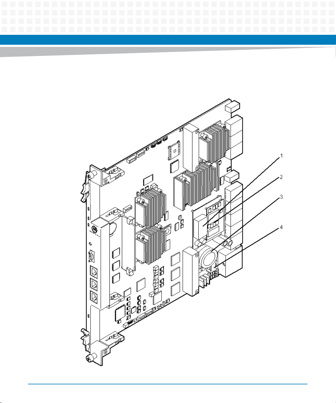
Figure 2-1 Critical Temperature Spots
26
ATCA-F120 Installation and Use (6806800D06J)

Hardware Preparation and Installation
Table 2-2 Critical Temperature Limits
Temperature in
Location Temperature in Celsius
1 85°C 185°F Top center of DC/DC converter used
2 100°C 212°F PCB surface of main DC/DC
3 105°C 221°F Big capacitor, margin which faces
4 90°C 194°F Top center of filter coil
Fahrenheit Description
for management power
converter
the DC/DC converter
2.3.2 Power Requirements
Make sure that the blade is used in an AdvancedTCA shelf connected to -48VDC up to -60VDC,
according to Telecommunication Network Voltage (TNV-2). A TNV-2 circuit is a circuit whose
normal operating voltages exceed the limits for a safety-extra-low-voltage (SELV) under
normal operating conditions, and which is not subject to over-voltages from
telecommunication networks.
Table 2-3 DC System Power Requirements
Feature Value
Rated voltage -48VDC to -60VDC
Operating voltage -40.0VDC to -72VDC
Input current max. 5.0A@40V
Power dissipation max. 200W
ATCA-F120 Installation and Use (6806800D06J)
US and Canada: -48VDC
US and Canada: -40.0 to -60VDC
The tested blade was a ATCA-F120 blade, including two
installed AMC modules (35W each), and an RTM-ATCAF120-COP (30W).
27

Hardware Preparation and Installation
2.4 Installing Rear Transition Modules
As of writing this guide, the following rear transition module (RTM) were available: RTM-ATCAF120C and RTM-ATCA-F120-OPT
The RTMs are not hot-swappable. Before you install them, you must make sure that either no
front blade is installed in the respective slot, or that the front blade is powered-down. For
further details about the RTM installation refer to the Installation and Use guide of the
respective RTM.
2.5 Configuring the Blade
The blade provides the configuration switches SW1, SW2, SW3 and SW4. Their location is
shown in the following figure. The switch settings shown in the figure correspond to the
default settings. The switches are displayed as the small white squares.
28
ATCA-F120 Installation and Use (6806800D06J)
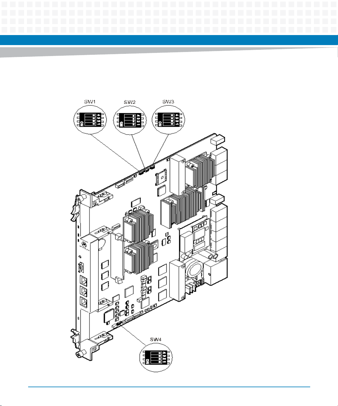
Figure 2-2 On-Board Configuration Switches
Hardware Preparation and Installation
ATCA-F120 Installation and Use (6806800D06J)
29
Hardware Preparation and Installation
Blade Malfunction
Switches marked as 'reserved' might carry production-related functions and can cause the
blade to malfunction if their setting is changed.
Therefore, do not change settings of switches marked as 'reserved'. The setting of switches
which are not marked as 'reserved' has to be checked and changed before blade installation.
Blade Damage
Setting/resetting the switches during operation can cause blade damage.
Therefore, check and change switch settings before you install the blade.
Table 2-4 Switch Settings
Switch Description
SW1-1 Selects whether the shelf manager (ShM) is accessed through Base
Channel port 1 or Update channel port 0. For details refer to Shelf
Manager Cross Connection on page 78.
Note that this switch setting can be overwritten via IPMI.
OFF: ShM is accessed through Update Channel port 0 (default)
ON: ShM is accessed through Base Channel port 1
SW1-2 Reserved (default: OFF)
SW1-3 Reserved (default: OFF)
SW1-4 Reserved (default: OFF)
SW2-1 and SW2-2 Serial interface routing
SW2-1 OFF and SW2-2 OFF (default): Serial interface of CPU is routed to
the F120 face blade and serial interface at RTM is disabled
SW2-1 ON and SW2-2 OFF: serial interface of CPU is routed to theRTM’s
face plate and serial interface of IPMC is routed to the F120 face plate (for
debugging only)
Other switch settings: Reserved
SW2-3 User flash #1 write protection. See User Flashes on page 69 and Memory
Map on page 95 for further details.
OFF: User flash #1 write-enabled (default)
ON: User flash #2 write-protected
30
ATCA-F120 Installation and Use (6806800D06J)
 Loading...