

Page 1

ATCA-7470
Installation and Use
P/N: 6806800P15K
October 2014
Page 2

©
Copyright 2014 Artesyn Embedded Technologies, Inc.
All rights reserved.
Trademarks
Artesyn Embedded Technologies, Artesyn and the Artesyn Embedded Technologies logo are trademarks and service marks of
Artesyn Embedded Technologies, Inc.© 2014 Artesyn Embedded Technologies, Inc. All other product or service names are the
property of their respective owners.
Intel® is a trademark or registered trademark of Intel Corporation or its subsidiaries in the United States and other countries.
Java™ and all other Java-based marks are trademarks or registered trademarks of Oracle America, Inc. in the U.S. and other countries.
Microsoft®, Windows® and Windows Me® are registered trademarks of Microsoft Corporation; and Windows XP™ is a trademark of
Microsoft Corporation.
PICMG®, CompactPCI®, AdvancedTCA™ and the PICMG, CompactPCI and AdvancedTCA logos are registered trademarks of the PCI
Industrial Computer Manufacturers Group.
UNIX® is a registered trademark of The Open Group in the United States and other countries.
Notice
While reasonable efforts have been made to assure the accuracy of this document, Artesyn assumes no liability resulting from any
omissions in this document, or from the use of the information obtained therein. Artesyn reserves the right to revise this document
and to make changes from time to time in the content hereof without obligation of Artesyn to notify any person of such revision or
changes.
Electronic versions of this material may be read online, downloaded for personal use, or referenced in another document as a URL to
an Artesyn website. The text itself may not be published commercially in print or electronic form, edited, translated, or otherwise
altered without the permission of Artesyn.
It is possible that this publication may contain reference to or information about Artesyn products (machines and programs),
programming, or services that are not available in your country. Such references or information must not be construed to mean that
Artesyn intends to announce such Artesyn products, programming, or services in your country.
Limited and Restricted Rights Legend
If the documentation contained herein is supplied, directly or indirectly, to the U.S. Government, the following notice shall apply
unless otherwise agreed to in writing by Artesyn.
Use, duplication, or disclosure by the Government is subject to restrictions as set forth in subparagraph (b)(3) of the Rights in
Technical Data clause at DFARS 252.227-7013 (Nov. 1995) and of the Rights in Noncommercial Computer Software and
Documentation clause at DFARS 252.227-7014 (Jun. 1995).
Contact Address
Artesyn Embedded Technologies Artesyn Embedded Technologies
Marketing Communications
2900 S. Diablo Way, Suite 190
Tempe, Arizona 85282
Lilienthalstr. 17-19
85579 Neubiberg/Munich
Germany
Page 3

Contents
Contents
About this Manual . . . . . . . . . . . . . . . . . . . . . . . . . . . . . . . . . . . . . . . . . . . . . . . . . . . . . . . . . . . . . . . . . . . . . . . 19
Safety Notes . . . . . . . . . . . . . . . . . . . . . . . . . . . . . . . . . . . . . . . . . . . . . . . . . . . . . . . . . . . . . . . . . . . . . . . . . . . . . 25
Sicherheitshinweise . . . . . . . . . . . . . . . . . . . . . . . . . . . . . . . . . . . . . . . . . . . . . . . . . . . . . . . . . . . . . . . . . . . . . . 29
1 Introduction . . . . . . . . . . . . . . . . . . . . . . . . . . . . . . . . . . . . . . . . . . . . . . . . . . . . . . . . . . . . . . . . . . . . . . . . . 35
1.1 Features . . . . . . . . . . . . . . . . . . . . . . . . . . . . . . . . . . . . . . . . . . . . . . . . . . . . . . . . . . . . . . . . . . . . . . . . . . . 35
1.2 Standard Compliances . . . . . . . . . . . . . . . . . . . . . . . . . . . . . . . . . . . . . . . . . . . . . . . . . . . . . . . . . . . . . . 37
1.3 Mechanical Data . . . . . . . . . . . . . . . . . . . . . . . . . . . . . . . . . . . . . . . . . . . . . . . . . . . . . . . . . . . . . . . . . . . 40
1.4 Product Identification . . . . . . . . . . . . . . . . . . . . . . . . . . . . . . . . . . . . . . . . . . . . . . . . . . . . . . . . . . . . . . . 41
1.5 Ordering Information . . . . . . . . . . . . . . . . . . . . . . . . . . . . . . . . . . . . . . . . . . . . . . . . . . . . . . . . . . . . . . . 42
2 Hardware Preparation and Installation . . . . . . . . . . . . . . . . . . . . . . . . . . . . . . . . . . . . . . . . . . . . . . . . . 45
2.1 Unpacking and Inspecting the Blade . . . . . . . . . . . . . . . . . . . . . . . . . . . . . . . . . . . . . . . . . . . . . . . . . . 45
2.2 Environmental and Power Requirements . . . . . . . . . . . . . . . . . . . . . . . . . . . . . . . . . . . . . . . . . . . . . . 45
2.2.1 Environmental Requirements. . . . . . . . . . . . . . . . . . . . . . . . . . . . . . . . . . . . . . . . . . . . . . . . . . 46
2.2.2 Power Requirements . . . . . . . . . . . . . . . . . . . . . . . . . . . . . . . . . . . . . . . . . . . . . . . . . . . . . . . . . 49
2.3 Blade Layout . . . . . . . . . . . . . . . . . . . . . . . . . . . . . . . . . . . . . . . . . . . . . . . . . . . . . . . . . . . . . . . . . . . . . . . 52
2.4 Switch Settings . . . . . . . . . . . . . . . . . . . . . . . . . . . . . . . . . . . . . . . . . . . . . . . . . . . . . . . . . . . . . . . . . . . . . 53
2.5 Installing the Blade Accessories . . . . . . . . . . . . . . . . . . . . . . . . . . . . . . . . . . . . . . . . . . . . . . . . . . . . . . 56
2.5.1 DIMM Memory Modules . . . . . . . . . . . . . . . . . . . . . . . . . . . . . . . . . . . . . . . . . . . . . . . . . . . . . . 56
2.5.2 MO297 SSD Module . . . . . . . . . . . . . . . . . . . . . . . . . . . . . . . . . . . . . . . . . . . . . . . . . . . . . . . . . . 58
2.5.3 Accelerator Module . . . . . . . . . . . . . . . . . . . . . . . . . . . . . . . . . . . . . . . . . . . . . . . . . . . . . . . . . . 60
2.6 Installing and Removing the Blade . . . . . . . . . . . . . . . . . . . . . . . . . . . . . . . . . . . . . . . . . . . . . . . . . . . . 61
2.6.1 Installing the Blade . . . . . . . . . . . . . . . . . . . . . . . . . . . . . . . . . . . . . . . . . . . . . . . . . . . . . . . . . . . 61
2.6.2 Removing the Blade . . . . . . . . . . . . . . . . . . . . . . . . . . . . . . . . . . . . . . . . . . . . . . . . . . . . . . . . . . 64
3 Controls, Indicators, and Connectors . . . . . . . . . . . . . . . . . . . . . . . . . . . . . . . . . . . . . . . . . . . . . . . . . . . 67
3.1 Face Plate . . . . . . . . . . . . . . . . . . . . . . . . . . . . . . . . . . . . . . . . . . . . . . . . . . . . . . . . . . . . . . . . . . . . . . . . . 67
3.1.1 LEDs. . . . . . . . . . . . . . . . . . . . . . . . . . . . . . . . . . . . . . . . . . . . . . . . . . . . . . . . . . . . . . . . . . . . . . . . 68
3.1.2 Keys . . . . . . . . . . . . . . . . . . . . . . . . . . . . . . . . . . . . . . . . . . . . . . . . . . . . . . . . . . . . . . . . . . . . . . . . 69
3.1.3 Connectors. . . . . . . . . . . . . . . . . . . . . . . . . . . . . . . . . . . . . . . . . . . . . . . . . . . . . . . . . . . . . . . . . . 69
ATCA-7470 Installation and Use (6806800P15K)
3
Page 4

Contents
Contents
Contents
3.1.3.1 Serial COM#1 P17 . . . . . . . . . . . . . . . . . . . . . . . . . . . . . . . . . . . . . . . . . . . . . . . . . . . 70
3.1.3.2 Ethernet Connector . . . . . . . . . . . . . . . . . . . . . . . . . . . . . . . . . . . . . . . . . . . . . . . . . 70
3.1.3.3 Serial Interface Connector . . . . . . . . . . . . . . . . . . . . . . . . . . . . . . . . . . . . . . . . . . . 71
3.1.3.4 USB Connectors . . . . . . . . . . . . . . . . . . . . . . . . . . . . . . . . . . . . . . . . . . . . . . . . . . . . 72
3.2 On-board Connectors . . . . . . . . . . . . . . . . . . . . . . . . . . . . . . . . . . . . . . . . . . . . . . . . . . . . . . . . . . . . . . . 72
3.2.1 MO297 SSD Module Connector . . . . . . . . . . . . . . . . . . . . . . . . . . . . . . . . . . . . . . . . . . . . . . . . 72
3.3 AdvancedTCA Backplane Connectors . . . . . . . . . . . . . . . . . . . . . . . . . . . . . . . . . . . . . . . . . . . . . . . . . 74
4 BIOS . . . . . . . . . . . . . . . . . . . . . . . . . . . . . . . . . . . . . . . . . . . . . . . . . . . . . . . . . . . . . . . . . . . . . . . . . . . . . . . . 83
4.1 Introduction . . . . . . . . . . . . . . . . . . . . . . . . . . . . . . . . . . . . . . . . . . . . . . . . . . . . . . . . . . . . . . . . . . . . . . . 83
4.2 Accessing the Blade Using the Serial Console Redirection . . . . . . . . . . . . . . . . . . . . . . . . . . . . . . . . 84
4.2.1 Requirements for Serial Console Redirection . . . . . . . . . . . . . . . . . . . . . . . . . . . . . . . . . . . . 84
4.2.2 Default Access Parameters . . . . . . . . . . . . . . . . . . . . . . . . . . . . . . . . . . . . . . . . . . . . . . . . . . . . 84
4.2.3 Connecting to the Blade . . . . . . . . . . . . . . . . . . . . . . . . . . . . . . . . . . . . . . . . . . . . . . . . . . . . . . 85
4.3 Changing Configuration Settings . . . . . . . . . . . . . . . . . . . . . . . . . . . . . . . . . . . . . . . . . . . . . . . . . . . . . 85
4.4 Boot Options . . . . . . . . . . . . . . . . . . . . . . . . . . . . . . . . . . . . . . . . . . . . . . . . . . . . . . . . . . . . . . . . . . . . . . . 87
4.4.1 Supported Boot Devices . . . . . . . . . . . . . . . . . . . . . . . . . . . . . . . . . . . . . . . . . . . . . . . . . . . . . . 87
4.4.2 Selecting the Boot Device . . . . . . . . . . . . . . . . . . . . . . . . . . . . . . . . . . . . . . . . . . . . . . . . . . . . . 87
4.4.3 By Boot Menu. . . . . . . . . . . . . . . . . . . . . . . . . . . . . . . . . . . . . . . . . . . . . . . . . . . . . . . . . . . . . . . . 89
4.5 IPMI Boot Parameter . . . . . . . . . . . . . . . . . . . . . . . . . . . . . . . . . . . . . . . . . . . . . . . . . . . . . . . . . . . . . . . . 90
4.6 Restoring BIOS Default Settings . . . . . . . . . . . . . . . . . . . . . . . . . . . . . . . . . . . . . . . . . . . . . . . . . . . . . . 91
4.7 BIOS Setup Configuration . . . . . . . . . . . . . . . . . . . . . . . . . . . . . . . . . . . . . . . . . . . . . . . . . . . . . . . . . . . 92
4.7.1 Main. . . . . . . . . . . . . . . . . . . . . . . . . . . . . . . . . . . . . . . . . . . . . . . . . . . . . . . . . . . . . . . . . . . . . . . . 92
4.7.2 Advanced . . . . . . . . . . . . . . . . . . . . . . . . . . . . . . . . . . . . . . . . . . . . . . . . . . . . . . . . . . . . . . . . . . . 93
4.7.3 IPMI . . . . . . . . . . . . . . . . . . . . . . . . . . . . . . . . . . . . . . . . . . . . . . . . . . . . . . . . . . . . . . . . . . . . . . . . 98
4.7.4 Security. . . . . . . . . . . . . . . . . . . . . . . . . . . . . . . . . . . . . . . . . . . . . . . . . . . . . . . . . . . . . . . . . . . . . 99
4.7.5 Boot. . . . . . . . . . . . . . . . . . . . . . . . . . . . . . . . . . . . . . . . . . . . . . . . . . . . . . . . . . . . . . . . . . . . . . . 100
4.7.6 Exit . . . . . . . . . . . . . . . . . . . . . . . . . . . . . . . . . . . . . . . . . . . . . . . . . . . . . . . . . . . . . . . . . . . . . . . .100
4.7.7 CPU Performance Settings . . . . . . . . . . . . . . . . . . . . . . . . . . . . . . . . . . . . . . . . . . . . . . . . . . . 100
4.7.8 Memory Configuration . . . . . . . . . . . . . . . . . . . . . . . . . . . . . . . . . . . . . . . . . . . . . . . . . . . . . . 101
4.7.8.1 Independent Channel Mode . . . . . . . . . . . . . . . . . . . . . . . . . . . . . . . . . . . . . . . . . 101
4.7.8.2 Mirrored Channel Mode . . . . . . . . . . . . . . . . . . . . . . . . . . . . . . . . . . . . . . . . . . . . 101
4.7.8.3 Lockstep Channel Mode . . . . . . . . . . . . . . . . . . . . . . . . . . . . . . . . . . . . . . . . . . . .102
4.8 Restoring BIOS Default Settings . . . . . . . . . . . . . . . . . . . . . . . . . . . . . . . . . . . . . . . . . . . . . . . . . . . . . 102
4.9 IPMI Support . . . . . . . . . . . . . . . . . . . . . . . . . . . . . . . . . . . . . . . . . . . . . . . . . . . . . . . . . . . . . . . . . . . . . .103
4
ATCA-7470 Installation and Use (6806800P15K)
Page 5

Contents
4.10 Watchdog Support . . . . . . . . . . . . . . . . . . . . . . . . . . . . . . . . . . . . . . . . . . . . . . . . . . . . . . . . . . . . . . . .103
4.11 BIOS Error Logging . . . . . . . . . . . . . . . . . . . . . . . . . . . . . . . . . . . . . . . . . . . . . . . . . . . . . . . . . . . . . . . . . 104
4.11.1 Runtime Error Logging. . . . . . . . . . . . . . . . . . . . . . . . . . . . . . . . . . . . . . . . . . . . . . . . . . . . . . . 104
4.11.2 IPMI Error Logging. . . . . . . . . . . . . . . . . . . . . . . . . . . . . . . . . . . . . . . . . . . . . . . . . . . . . . . . . . . 106
4.11.3 SMBIOS Error Logging . . . . . . . . . . . . . . . . . . . . . . . . . . . . . . . . . . . . . . . . . . . . . . . . . . . . . . . 108
4.11.3.1 Single-bit ECC Memory Error . . . . . . . . . . . . . . . . . . . . . . . . . . . . . . . . . . . . . . . .109
4.11.3.2 Multi-bit ECC Memory Error . . . . . . . . . . . . . . . . . . . . . . . . . . . . . . . . . . . . . . . . . 110
4.11.3.3 POST Error . . . . . . . . . . . . . . . . . . . . . . . . . . . . . . . . . . . . . . . . . . . . . . . . . . . . . . . . 110
4.11.3.4 PCI Parity Error . . . . . . . . . . . . . . . . . . . . . . . . . . . . . . . . . . . . . . . . . . . . . . . . . . . . 112
4.11.3.5 PCI System Error . . . . . . . . . . . . . . . . . . . . . . . . . . . . . . . . . . . . . . . . . . . . . . . . . . . 113
4.11.3.6 CPU Failure . . . . . . . . . . . . . . . . . . . . . . . . . . . . . . . . . . . . . . . . . . . . . . . . . . . . . . . . 114
4.11.3.7 Correctable Memory Log Disabled . . . . . . . . . . . . . . . . . . . . . . . . . . . . . . . . . . . 114
4.11.3.8 Log Area Reset/Cleared . . . . . . . . . . . . . . . . . . . . . . . . . . . . . . . . . . . . . . . . . . . . .115
4.11.3.9 System Boot . . . . . . . . . . . . . . . . . . . . . . . . . . . . . . . . . . . . . . . . . . . . . . . . . . . . . . 115
4.12 LED Usage . . . . . . . . . . . . . . . . . . . . . . . . . . . . . . . . . . . . . . . . . . . . . . . . . . . . . . . . . . . . . . . . . . . . . . . . 115
4.13 Upgrading the BIOS . . . . . . . . . . . . . . . . . . . . . . . . . . . . . . . . . . . . . . . . . . . . . . . . . . . . . . . . . . . . . . . . 115
4.14 BIOS Status Codes . . . . . . . . . . . . . . . . . . . . . . . . . . . . . . . . . . . . . . . . . . . . . . . . . . . . . . . . . . . . . . . . . 116
5 Functional Description . . . . . . . . . . . . . . . . . . . . . . . . . . . . . . . . . . . . . . . . . . . . . . . . . . . . . . . . . . . . . . . 123
5.1 Block Diagram . . . . . . . . . . . . . . . . . . . . . . . . . . . . . . . . . . . . . . . . . . . . . . . . . . . . . . . . . . . . . . . . . . . . 123
5.2 Processor . . . . . . . . . . . . . . . . . . . . . . . . . . . . . . . . . . . . . . . . . . . . . . . . . . . . . . . . . . . . . . . . . . . . . . . . . 124
5.3 Memory . . . . . . . . . . . . . . . . . . . . . . . . . . . . . . . . . . . . . . . . . . . . . . . . . . . . . . . . . . . . . . . . . . . . . . . . . .124
5.4 Platform Controller Hub (PCH) . . . . . . . . . . . . . . . . . . . . . . . . . . . . . . . . . . . . . . . . . . . . . . . . . . . . . . 125
5.4.1 PCH I/O Controller Features . . . . . . . . . . . . . . . . . . . . . . . . . . . . . . . . . . . . . . . . . . . . . . . . . .126
5.4.2 PCH Intel QuickAssist and Quad MAC PCIe Endpoint . . . . . . . . . . . . . . . . . . . . . . . . . . . . .127
5.5 Firmware Flashes . . . . . . . . . . . . . . . . . . . . . . . . . . . . . . . . . . . . . . . . . . . . . . . . . . . . . . . . . . . . . . . . . . 128
5.6 Ethernet Ports . . . . . . . . . . . . . . . . . . . . . . . . . . . . . . . . . . . . . . . . . . . . . . . . . . . . . . . . . . . . . . . . . . . . . 129
5.6.1 ATCA Base IF Link Status Pass Through . . . . . . . . . . . . . . . . . . . . . . . . . . . . . . . . . . . . . . . . 129
5.6.1.1 Marvel Switch Initialization . . . . . . . . . . . . . . . . . . . . . . . . . . . . . . . . .130
5.7 Storage Controller . . . . . . . . . . . . . . . . . . . . . . . . . . . . . . . . . . . . . . . . . . . . . . . . . . . . . . . . . . . . . . . . .131
5.8 MO297 SlimSATA Embedded Solid State Disc (SSD) . . . . . . . . . . . . . . . . . . . . . . . . . . . . . . . . . . . . 131
5.9 BIOS . . . . . . . . . . . . . . . . . . . . . . . . . . . . . . . . . . . . . . . . . . . . . . . . . . . . . . . . . . . . . . . . . . . . . . . . . . . . . 131
5.10 IPMC . . . . . . . . . . . . . . . . . . . . . . . . . . . . . . . . . . . . . . . . . . . . . . . . . . . . . . . . . . . . . . . . . . . . . . . . . . . . .131
5.11 Serial Redirection . . . . . . . . . . . . . . . . . . . . . . . . . . . . . . . . . . . . . . . . . . . . . . . . . . . . . . . . . . . . . . . . . . 132
5.12 Serial Over LAN . . . . . . . . . . . . . . . . . . . . . . . . . . . . . . . . . . . . . . . . . . . . . . . . . . . . . . . . . . . . . . . . . . . . 133
ATCA-7470 Installation and Use (6806800P15K)
5
Page 6

Contents
Contents
Contents
5.13 Control Logic . . . . . . . . . . . . . . . . . . . . . . . . . . . . . . . . . . . . . . . . . . . . . . . . . . . . . . . . . . . . . . . . . . . . . 133
5.14 Front Board Face Plate . . . . . . . . . . . . . . . . . . . . . . . . . . . . . . . . . . . . . . . . . . . . . . . . . . . . . . . . . . . . . 133
5.15 Faceplate Serial Interfaces . . . . . . . . . . . . . . . . . . . . . . . . . . . . . . . . . . . . . . . . . . . . . . . . . . . . . . . . . . 134
5.15.1 IPMC Debug Console . . . . . . . . . . . . . . . . . . . . . . . . . . . . . . . . . . . . . . . . . . . . . . . . . . . . . . . . 135
5.16 USB 2.0 Interfaces . . . . . . . . . . . . . . . . . . . . . . . . . . . . . . . . . . . . . . . . . . . . . . . . . . . . . . . . . . . . . . . . . 135
5.17 LPC Interface . . . . . . . . . . . . . . . . . . . . . . . . . . . . . . . . . . . . . . . . . . . . . . . . . . . . . . . . . . . . . . . . . . . . . . 135
5.18 Trusted Platform Module . . . . . . . . . . . . . . . . . . . . . . . . . . . . . . . . . . . . . . . . . . . . . . . . . . . . . . . . . . . 135
5.19 Real Time Clock . . . . . . . . . . . . . . . . . . . . . . . . . . . . . . . . . . . . . . . . . . . . . . . . . . . . . . . . . . . . . . . . . . . 136
5.20 ATCA-7470 Accelerator Module Slot . . . . . . . . . . . . . . . . . . . . . . . . . . . . . . . . . . . . . . . . . . . . . . . . . 136
5.21 SMBus . . . . . . . . . . . . . . . . . . . . . . . . . . . . . . . . . . . . . . . . . . . . . . . . . . . . . . . . . . . . . . . . . . . . . . . . . . . 137
6 Maps and Registers . . . . . . . . . . . . . . . . . . . . . . . . . . . . . . . . . . . . . . . . . . . . . . . . . . . . . . . . . . . . . . . . . . 141
6.1 Interrupt Structure . . . . . . . . . . . . . . . . . . . . . . . . . . . . . . . . . . . . . . . . . . . . . . . . . . . . . . . . . . . . . . . . 141
6.1.1 Intel DH8900CC PCH NON-APIC (PIC mode) D31:F0 Interrupt Mapping . . . . . . . . . . . .142
6.1.2 Intel Cavecreek PCH DH8900CC APIC (D31:F0) Interrupt Mapping . . . . . . . . . . . . . . . .143
6.1.3 NMI Generation. . . . . . . . . . . . . . . . . . . . . . . . . . . . . . . . . . . . . . . . . . . . . . . . . . . . . . . . . . . . . 144
6.2 FPGA Registers . . . . . . . . . . . . . . . . . . . . . . . . . . . . . . . . . . . . . . . . . . . . . . . . . . . . . . . . . . . . . . . . . . . 145
6.3 Registers . . . . . . . . . . . . . . . . . . . . . . . . . . . . . . . . . . . . . . . . . . . . . . . . . . . . . . . . . . . . . . . . . . . . . . . . . 146
6.3.1 Register Decoding . . . . . . . . . . . . . . . . . . . . . . . . . . . . . . . . . . . . . . . . . . . . . . . . . . . . . . . . . . 147
6.3.1.1 LPC Decoding . . . . . . . . . . . . . . . . . . . . . . . . . . . . . . . . . . . . . . . . . . . . . . . . . . . . .147
6.3.1.2 SPI Register Decoding . . . . . . . . . . . . . . . . . . . . . . . . . . . . . . . . . . . . . . . . . . . . . . 148
6.3.2 POST Code Register . . . . . . . . . . . . . . . . . . . . . . . . . . . . . . . . . . . . . . . . . . . . . . . . . . . . . . . . . 148
6.4 FPGA Register Mapping . . . . . . . . . . . . . . . . . . . . . . . . . . . . . . . . . . . . . . . . . . . . . . . . . . . . . . . . . . . .150
6.4.1 LPC I/O Register Map . . . . . . . . . . . . . . . . . . . . . . . . . . . . . . . . . . . . . . . . . . . . . . . . . . . . . . . .150
6.4.2 IPMC SPI Register Map . . . . . . . . . . . . . . . . . . . . . . . . . . . . . . . . . . . . . . . . . . . . . . . . . . . . . . . 150
6.4.3 Module Identification Register . . . . . . . . . . . . . . . . . . . . . . . . . . . . . . . . . . . . . . . . . . . . . . . .153
6.4.4 Version Register . . . . . . . . . . . . . . . . . . . . . . . . . . . . . . . . . . . . . . . . . . . . . . . . . . . . . . . . . . . . 153
6.4.5 Serial Redirection Control Register . . . . . . . . . . . . . . . . . . . . . . . . . . . . . . . . . . . . . . . . . . . . 153
6.4.6 Serial over LAN (SOL) Control Register . . . . . . . . . . . . . . . . . . . . . . . . . . . . . . . . . . . . . . . . . 154
6.4.7 Serial Line Routing Register. . . . . . . . . . . . . . . . . . . . . . . . . . . . . . . . . . . . . . . . . . . . . . . . . . . 155
6.4.8 RTM SPI Interface Registers. . . . . . . . . . . . . . . . . . . . . . . . . . . . . . . . . . . . . . . . . . . . . . . . . . . 155
6.4.9 DIMM ADR Status Register . . . . . . . . . . . . . . . . . . . . . . . . . . . . . . . . . . . . . . . . . . . . . . . . . . .157
6.4.10 Reset Registers . . . . . . . . . . . . . . . . . . . . . . . . . . . . . . . . . . . . . . . . . . . . . . . . . . . . . . . . . . . . . 157
6.4.10.1 BIOS Reset Source Register . . . . . . . . . . . . . . . . . . . . . . . . . . . . . . . . . . . . . . . . . . 157
6.4.10.2 Reset Mask Register . . . . . . . . . . . . . . . . . . . . . . . . . . . . . . . . . . . . . . . . . . . . . . . .158
6
ATCA-7470 Installation and Use (6806800P15K)
Page 7

Contents
6.4.10.3 BIOS IPMC Watchdog Timeout Register . . . . . . . . . . . . . . . . . . . . . . . . . . . . . . . 159
6.4.10.4 BIOS Push Button Enable Register . . . . . . . . . . . . . . . . . . . . . . . . . . . . . . . . . . . . 160
6.4.10.5 OS Reset Source Register . . . . . . . . . . . . . . . . . . . . . . . . . . . . . . . . . . . . . . . . . . .160
6.4.10.6 OS IPMC Watchdog Timeout Register . . . . . . . . . . . . . . . . . . . . . . . . . . . . . . . . 161
6.4.10.7 IPMC Watchdog Timeout Register . . . . . . . . . . . . . . . . . . . . . . . . . . . . . . . . . . .162
6.4.10.8 IPMC Reset Source Register . . . . . . . . . . . . . . . . . . . . . . . . . . . . . . . . . . . . . . . . . 163
6.4.10.9 DIMM ADR Configuration Register . . . . . . . . . . . . . . . . . . . . . . . . . . . . . . . . . . . 164
6.4.10.10Software Reset Register . . . . . . . . . . . . . . . . . . . . . . . . . . . . . . . . . . . . . . . . . . . . 165
6.4.10.11FWH_PLTRST_ Enable Register . . . . . . . . . . . . . . . . . . . . . . . . . . . . . . . . . . . . . .165
6.4.11 Interrupt Control and Status Registers . . . . . . . . . . . . . . . . . . . . . . . . . . . . . . . . . . . . . . . . . 165
6.4.11.1 RTM Interrupt Status Register . . . . . . . . . . . . . . . . . . . . . . . . . . . . . . . . . . . . . . . 166
6.4.11.2 External Interrupt Status Register . . . . . . . . . . . . . . . . . . . . . . . . . . . . . . . . . . . . 166
6.4.11.3 Processor Hot Status Register . . . . . . . . . . . . . . . . . . . . . . . . . . . . . . . . . . . . . . .167
6.4.11.4 Telecom Interrupt Control/Status Register . . . . . . . . . . . . . . . . . . . . . . . . . . . .167
6.4.11.5 Interrupt Mask and Map Registers . . . . . . . . . . . . . . . . . . . . . . . . . . . . . . . . . . . . 168
6.4.11.6 Base Interface Link Interrupt Status Register . . . . . . . . . . . . . . . . . . . . . . . . . . . 171
6.4.12 PCI Express Hot Plug I2C IO Expander Registers . . . . . . . . . . . . . . . . . . . . . . . . . . . . . . . . . 171
6.4.12.1 Hot-Plug Virtual Pin Port Registers . . . . . . . . . . . . . . . . . . . . . . . . . . . . . . . . . . . 172
6.4.12.2 PCA9555 Internal Register Access . . . . . . . . . . . . . . . . . . . . . . . . . . . . . . . . . . . . 174
6.4.13 Flash Status and Protection Registers . . . . . . . . . . . . . . . . . . . . . . . . . . . . . . . . . . . . . . . . . .175
6.4.14 BIOS Boot Mode Register. . . . . . . . . . . . . . . . . . . . . . . . . . . . . . . . . . . . . . . . . . . . . . . . . . . . . 177
6.4.15 Update Channel Equalization Control Register . . . . . . . . . . . . . . . . . . . . . . . . . . . . . . . . . . 177
6.4.16 IPMC E-Keying Status Register . . . . . . . . . . . . . . . . . . . . . . . . . . . . . . . . . . . . . . . . . . . . . . . . 178
6.4.17 IPMC E-Keying Control Register . . . . . . . . . . . . . . . . . . . . . . . . . . . . . . . . . . . . . . . . . . . . . . . 179
6.4.18 LED Status and Control Register. . . . . . . . . . . . . . . . . . . . . . . . . . . . . . . . . . . . . . . . . . . . . . . 179
6.4.19 CPLD Revision Register . . . . . . . . . . . . . . . . . . . . . . . . . . . . . . . . . . . . . . . . . . . . . . . . . . . . . . 180
6.4.20 Spare Signals Status Registers . . . . . . . . . . . . . . . . . . . . . . . . . . . . . . . . . . . . . . . . . . . . . . . .180
6.4.21 DIMM Event Register . . . . . . . . . . . . . . . . . . . . . . . . . . . . . . . . . . . . . . . . . . . . . . . . . . . . . . . .181
6.4.22 CPU Type and Presence Detection Register. . . . . . . . . . . . . . . . . . . . . . . . . . . . . . . . . . . . . 182
6.4.23 Memory Temperature Status Register . . . . . . . . . . . . . . . . . . . . . . . . . . . . . . . . . . . . . . . . . 182
6.4.24 Base Interface link Status Signals Register . . . . . . . . . . . . . . . . . . . . . . . . . . . . . . . . . . . . . . 183
6.4.25 Miscellaneous Status/Control Registers . . . . . . . . . . . . . . . . . . . . . . . . . . . . . . . . . . . . . . . . 184
6.4.26 Telecom Clock Control and Supervision Registers . . . . . . . . . . . . . . . . . . . . . . . . . . . . . . . 185
6.4.26.1 Telecom Clock Device Control/Status Registers . . . . . . . . . . . . . . . . . . . . . . . . 185
6.4.26.2 Telecom Clock Enable and Routing Register . . . . . . . . . . . . . . . . . . . . . . . . . . . 187
6.4.26.3 Telecom Clock Monitor Registers . . . . . . . . . . . . . . . . . . . . . . . . . . . . . . . . . . . . 188
ATCA-7470 Installation and Use (6806800P15K)
7
Page 8

Contents
Contents
Contents
6.4.27 Serial Management Interface (MII) Control Registers . . . . . . . . . . . . . . . . . . . . . . . . . . . . 193
6.4.28 Scratch Registers. . . . . . . . . . . . . . . . . . . . . . . . . . . . . . . . . . . . . . . . . . . . . . . . . . . . . . . . . . . . 195
7 Serial Over LAN . . . . . . . . . . . . . . . . . . . . . . . . . . . . . . . . . . . . . . . . . . . . . . . . . . . . . . . . . . . . . . . . . . . . .197
7.1 Overview . . . . . . . . . . . . . . . . . . . . . . . . . . . . . . . . . . . . . . . . . . . . . . . . . . . . . . . . . . . . . . . . . . . . . . . . . 197
7.2 Installing the ipmitool . . . . . . . . . . . . . . . . . . . . . . . . . . . . . . . . . . . . . . . . . . . . . . . . . . . . . . . . . . . . . . 197
7.3 Configuring SOL Parameters . . . . . . . . . . . . . . . . . . . . . . . . . . . . . . . . . . . . . . . . . . . . . . . . . . . . . . . . 198
7.3.1 Using Standard IPMI Commands . . . . . . . . . . . . . . . . . . . . . . . . . . . . . . . . . . . . . . . . . . . . . . 198
7.3.2 Using ipmitool . . . . . . . . . . . . . . . . . . . . . . . . . . . . . . . . . . . . . . . . . . . . . . . . . . . . . . . . . . . . . .199
7.4 Establishing an SOL Session . . . . . . . . . . . . . . . . . . . . . . . . . . . . . . . . . . . . . . . . . . . . . . . . . . . . . . . . .201
8 Boot Bank Selection . . . . . . . . . . . . . . . . . . . . . . . . . . . . . . . . . . . . . . . . . . . . . . . . . . . . . . . . . . . . . . . . . 203
8.1 BIOS Boot Bank Selection . . . . . . . . . . . . . . . . . . . . . . . . . . . . . . . . . . . . . . . . . . . . . . . . . . . . . . . . . . . 203
8.1.1 Boot Bank Sensor . . . . . . . . . . . . . . . . . . . . . . . . . . . . . . . . . . . . . . . . . . . . . . . . . . . . . . . . . . . 203
8.1.2 Fail Safe Logic. . . . . . . . . . . . . . . . . . . . . . . . . . . . . . . . . . . . . . . . . . . . . . . . . . . . . . . . . . . . . . . 203
8.2 Glue Logic FPGA Flash Selection . . . . . . . . . . . . . . . . . . . . . . . . . . . . . . . . . . . . . . . . . . . . . . . . . . . . . 205
9 Supported IPMI Commands . . . . . . . . . . . . . . . . . . . . . . . . . . . . . . . . . . . . . . . . . . . . . . . . . . . . . . . . . . 207
9.1 Standard IPMI Commands . . . . . . . . . . . . . . . . . . . . . . . . . . . . . . . . . . . . . . . . . . . . . . . . . . . . . . . . . . 207
9.1.1 Global IPMI Commands . . . . . . . . . . . . . . . . . . . . . . . . . . . . . . . . . . . . . . . . . . . . . . . . . . . . . . 207
9.1.2 System Interface Commands . . . . . . . . . . . . . . . . . . . . . . . . . . . . . . . . . . . . . . . . . . . . . . . . . 207
9.1.3 Watchdog Commands. . . . . . . . . . . . . . . . . . . . . . . . . . . . . . . . . . . . . . . . . . . . . . . . . . . . . . . 208
9.1.4 SEL Device Commands. . . . . . . . . . . . . . . . . . . . . . . . . . . . . . . . . . . . . . . . . . . . . . . . . . . . . . . 209
9.1.5 FRU Inventory Commands. . . . . . . . . . . . . . . . . . . . . . . . . . . . . . . . . . . . . . . . . . . . . . . . . . . . 209
9.1.6 Sensor Device Commands. . . . . . . . . . . . . . . . . . . . . . . . . . . . . . . . . . . . . . . . . . . . . . . . . . . . 210
9.1.7 Chassis Device Commands . . . . . . . . . . . . . . . . . . . . . . . . . . . . . . . . . . . . . . . . . . . . . . . . . . . 211
9.1.7.1 System Boot Options Commands . . . . . . . . . . . . . . . . . . . . . . . . . . . . . . . . . . . . 211
9.1.8 LAN Device Commands . . . . . . . . . . . . . . . . . . . . . . . . . . . . . . . . . . . . . . . . . . . . . . . . . . . . . . 222
9.2 PICMG 3.0 Commands . . . . . . . . . . . . . . . . . . . . . . . . . . . . . . . . . . . . . . . . . . . . . . . . . . . . . . . . . . . . . 223
9.2.1 Set/Get Power Level . . . . . . . . . . . . . . . . . . . . . . . . . . . . . . . . . . . . . . . . . . . . . . . . . . . . . . . . . 224
9.3 Artesyn Specific Commands . . . . . . . . . . . . . . . . . . . . . . . . . . . . . . . . . . . . . . . . . . . . . . . . . . . . . . . .225
9.3.1 Serial Output Commands . . . . . . . . . . . . . . . . . . . . . . . . . . . . . . . . . . . . . . . . . . . . . . . . . . . .225
9.3.1.1 Set Serial Output Command . . . . . . . . . . . . . . . . . . . . . . . . . . . . . . . . . . . . . . . . . 225
8
ATCA-7470 Installation and Use (6806800P15K)
Page 9

Contents
9.3.1.2 Get Serial Output Command . . . . . . . . . . . . . . . . . . . . . . . . . . . . . . . . . . . . . . . . 227
9.3.2 OEM Command to configure IPMI Features. . . . . . . . . . . . . . . . . . . . . . . . . . . . . . . . . . . . . 228
9.3.2.1 Set Feature Configuration . . . . . . . . . . . . . . . . . . . . . . . . . . . . . . . . . . . . . . . . . . . 229
9.3.2.2 Get Feature Configuration . . . . . . . . . . . . . . . . . . . . . . . . . . . . . . . . . . . . . . . . . .230
9.4 Pigeon Point Specific Commands . . . . . . . . . . . . . . . . . . . . . . . . . . . . . . . . . . . . . . . . . . . . . . . . . . . . 231
9.4.1 Get Status Command. . . . . . . . . . . . . . . . . . . . . . . . . . . . . . . . . . . . . . . . . . . . . . . . . . . . . . . . 233
9.4.2 Get Serial Interface Properties Command . . . . . . . . . . . . . . . . . . . . . . . . . . . . . . . . . . . . . . 236
9.4.3 Set Serial Interface Properties Command. . . . . . . . . . . . . . . . . . . . . . . . . . . . . . . . . . . . . . . 237
9.4.4 Get Debug Level Command . . . . . . . . . . . . . . . . . . . . . . . . . . . . . . . . . . . . . . . . . . . . . . . . . .238
9.4.5 Set Debug Level Command. . . . . . . . . . . . . . . . . . . . . . . . . . . . . . . . . . . . . . . . . . . . . . . . . . . 239
9.4.6 Get Hardware Address Command . . . . . . . . . . . . . . . . . . . . . . . . . . . . . . . . . . . . . . . . . . . . .240
9.4.7 Set Hardware Address Command . . . . . . . . . . . . . . . . . . . . . . . . . . . . . . . . . . . . . . . . . . . . . 240
9.4.8 Get Handle Switch Command . . . . . . . . . . . . . . . . . . . . . . . . . . . . . . . . . . . . . . . . . . . . . . . . 241
9.4.9 Set Handle Switch Command. . . . . . . . . . . . . . . . . . . . . . . . . . . . . . . . . . . . . . . . . . . . . . . . . 242
9.4.10 Get Payload Communication Time-Out Command . . . . . . . . . . . . . . . . . . . . . . . . . . . . . . 242
9.4.11 Set Payload Communication Time-Out Command . . . . . . . . . . . . . . . . . . . . . . . . . . . . . . 243
9.4.12 Enable Payload Control Command . . . . . . . . . . . . . . . . . . . . . . . . . . . . . . . . . . . . . . . . . . . .244
9.4.13 Disable Payload Control Command. . . . . . . . . . . . . . . . . . . . . . . . . . . . . . . . . . . . . . . . . . . . 244
9.4.14 Reset IPMC Command . . . . . . . . . . . . . . . . . . . . . . . . . . . . . . . . . . . . . . . . . . . . . . . . . . . . . . . 245
9.4.15 Hang IPMC Command . . . . . . . . . . . . . . . . . . . . . . . . . . . . . . . . . . . . . . . . . . . . . . . . . . . . . . . 245
9.4.16 Graceful Reset Command . . . . . . . . . . . . . . . . . . . . . . . . . . . . . . . . . . . . . . . . . . . . . . . . . . . . 246
9.4.17 Get Payload Shutdown Time-Out Command . . . . . . . . . . . . . . . . . . . . . . . . . . . . . . . . . . . 247
9.4.18 Set Payload Shutdown Time-Out Command. . . . . . . . . . . . . . . . . . . . . . . . . . . . . . . . . . . . 248
9.4.19 Get Module State Command . . . . . . . . . . . . . . . . . . . . . . . . . . . . . . . . . . . . . . . . . . . . . . . . . 248
9.4.20 Enable Module Site Command . . . . . . . . . . . . . . . . . . . . . . . . . . . . . . . . . . . . . . . . . . . . . . . .250
9.4.21 Disable Module Site Command . . . . . . . . . . . . . . . . . . . . . . . . . . . . . . . . . . . . . . . . . . . . . . .250
9.4.22 Reset Carrier SDR Repository Command . . . . . . . . . . . . . . . . . . . . . . . . . . . . . . . . . . . . . . . 251
10 FRU Information and Sensor Data Records . . . . . . . . . . . . . . . . . . . . . . . . . . . . . . . . . . . . . . . . . . . . . 253
10.1 FRU Information . . . . . . . . . . . . . . . . . . . . . . . . . . . . . . . . . . . . . . . . . . . . . . . . . . . . . . . . . . . . . . . . . . . 253
10.2 MAC Address FRU OEM Records . . . . . . . . . . . . . . . . . . . . . . . . . . . . . . . . . . . . . . . . . . . . . . . . . . . . . 254
10.3 Power Configuration . . . . . . . . . . . . . . . . . . . . . . . . . . . . . . . . . . . . . . . . . . . . . . . . . . . . . . . . . . . . . . .256
10.4 Sensor Data Records . . . . . . . . . . . . . . . . . . . . . . . . . . . . . . . . . . . . . . . . . . . . . . . . . . . . . . . . . . . . . . . 256
ATCA-7470 Installation and Use (6806800P15K)
9
Page 10

Contents
Contents
Contents
11 Firmware Upgrade . . . . . . . . . . . . . . . . . . . . . . . . . . . . . . . . . . . . . . . . . . . . . . . . . . . . . . . . . . . . . . . . . . 271
11.1 HPM.1 Firmware Upgrade . . . . . . . . . . . . . . . . . . . . . . . . . . . . . . . . . . . . . . . . . . . . . . . . . . . . . . . . . . 271
11.1.1 Overview. . . . . . . . . . . . . . . . . . . . . . . . . . . . . . . . . . . . . . . . . . . . . . . . . . . . . . . . . . . . . . . . . . . 271
11.1.2 Installing the Ipmitool . . . . . . . . . . . . . . . . . . . . . . . . . . . . . . . . . . . . . . . . . . . . . . . . . . . . . . .271
11.1.2.1 Update Procedure . . . . . . . . . . . . . . . . . . . . . . . . . . . . . . . . . . . . . . . . . . . . . . . . . 271
11.1.3 Interface . . . . . . . . . . . . . . . . . . . . . . . . . . . . . . . . . . . . . . . . . . . . . . . . . . . . . . . . . . . . . . . . . . . 272
11.1.3.1 KCS Interface . . . . . . . . . . . . . . . . . . . . . . . . . . . . . . . . . . . . . . . . . . . . . . . . . . . . . . 272
11.1.3.2 IPMB-0 . . . . . . . . . . . . . . . . . . . . . . . . . . . . . . . . . . . . . . . . . . . . . . . . . . . . . . . . . . . 272
11.1.3.3 IPMI over LAN (BASE) . . . . . . . . . . . . . . . . . . . . . . . . . . . . . . . . . . . . . . . . . . . . . . . 272
11.2 IPMC Upgrade . . . . . . . . . . . . . . . . . . . . . . . . . . . . . . . . . . . . . . . . . . . . . . . . . . . . . . . . . . . . . . . . . . . . . 273
11.3 BIOS/FPGA Upgrade . . . . . . . . . . . . . . . . . . . . . . . . . . . . . . . . . . . . . . . . . . . . . . . . . . . . . . . . . . . . . . .274
11.4 Upgrade Package . . . . . . . . . . . . . . . . . . . . . . . . . . . . . . . . . . . . . . . . . . . . . . . . . . . . . . . . . . . . . . . . . . 276
A Replacing the Battery . . . . . . . . . . . . . . . . . . . . . . . . . . . . . . . . . . . . . . . . . . . . . . . . . . . . . . . . . . . . . . . . 277
A.1 Replacing the Battery . . . . . . . . . . . . . . . . . . . . . . . . . . . . . . . . . . . . . . . . . . . . . . . . . . . . . . . . . . . . . . 277
B Related Documentation. . . . . . . . . . . . . . . . . . . . . . . . . . . . . . . . . . . . . . . . . . . . . . . . . . . . . . . . . . . . . . 281
B.1 Artesyn Embedded Technologies - Embedded Computing Documentation . . . . . . . . . . . . . . .281
B.2 Manufacturers’ Documents . . . . . . . . . . . . . . . . . . . . . . . . . . . . . . . . . . . . . . . . . . . . . . . . . . . . . . . . . 282
B.3 Related Specifications . . . . . . . . . . . . . . . . . . . . . . . . . . . . . . . . . . . . . . . . . . . . . . . . . . . . . . . . . . . . . . 282
10
ATCA-7470 Installation and Use (6806800P15K)
Page 11

List of Tables
Table 1-1 Standard Compliances . . . . . . . . . . . . . . . . . . . . . . . . . . . . . . . . . . . . . . . . . . . . . . . . . . . . . . . . . . 37
Table 1-2 Mechanical Data . . . . . . . . . . . . . . . . . . . . . . . . . . . . . . . . . . . . . . . . . . . . . . . . . . . . . . . . . . . . . . . 40
Table 1-3 Blade Variants . . . . . . . . . . . . . . . . . . . . . . . . . . . . . . . . . . . . . . . . . . . . . . . . . . . . . . . . . . . . . . . . . 42
Table 1-4 Blade Accessories . . . . . . . . . . . . . . . . . . . . . . . . . . . . . . . . . . . . . . . . . . . . . . . . . . . . . . . . . . . . . . 42
Table 2-1 Environmental Requirements . . . . . . . . . . . . . . . . . . . . . . . . . . . . . . . . . . . . . . . . . . . . . . . . . . . . 47
Table 2-2 Critical Temperature Limits . . . . . . . . . . . . . . . . . . . . . . . . . . . . . . . . . . . . . . . . . . . . . . . . . . . . . . 49
Table 2-3 Power Requirements . . . . . . . . . . . . . . . . . . . . . . . . . . . . . . . . . . . . . . . . . . . . . . . . . . . . . . . . . . . 50
Table 2-4 Switch SW1 settings . . . . . . . . . . . . . . . . . . . . . . . . . . . . . . . . . . . . . . . . . . . . . . . . . . . . . . . . . . . . 54
Table 2-5 Switch SW2 Settings . . . . . . . . . . . . . . . . . . . . . . . . . . . . . . . . . . . . . . . . . . . . . . . . . . . . . . . . . . . . 54
Table 2-6 Switch SW3 Settings . . . . . . . . . . . . . . . . . . . . . . . . . . . . . . . . . . . . . . . . . . . . . . . . . . . . . . . . . . . . 55
Table 2-7 Switch SW4 Settings . . . . . . . . . . . . . . . . . . . . . . . . . . . . . . . . . . . . . . . . . . . . . . . . . . . . . . . . . . . . 55
Table 3-1 Face Plate LEDs . . . . . . . . . . . . . . . . . . . . . . . . . . . . . . . . . . . . . . . . . . . . . . . . . . . . . . . . . . . . . . . . 68
Table 3-2 RJ45 female Serial Line Connector pinout . . . . . . . . . . . . . . . . . . . . . . . . . . . . . . . . . . . . . . . . . 70
Table 4-1 Main . . . . . . . . . . . . . . . . . . . . . . . . . . . . . . . . . . . . . . . . . . . . . . . . . . . . . . . . . . . . . . . . . . . . . . . . . 92
Table 4-2 Main -> Boot Configuration . . . . . . . . . . . . . . . . . . . . . . . . . . . . . . . . . . . . . . . . . . . . . . . . . . . . . . 92
Table 4-3 Advanced --> RTM Configuration . . . . . . . . . . . . . . . . . . . . . . . . . . . . . . . . . . . . . . . . . . . . . . . . . 93
Table 4-4 Advanced --> CPU Configuration . . . . . . . . . . . . . . . . . . . . . . . . . . . . . . . . . . . . . . . . . . . . . . . . . 94
Table 4-5 Advanced --> CPU Configuration -> Processor Power Management . . . . . . . . . . . . . . . . . . . 94
Table 4-6 Advanced --> CPU Configuration -> System Agent (SA) Configuration . . . . . . . . . . . . . . . . . 95
Table 4-7 Advanced --> CPU Configuration -> System Agent (SA) Configuration -> Intel (R) I/O
Acceleration Technology 95
Table 4-8 Advanced --> Memory Configuration . . . . . . . . . . . . . . . . . . . . . . . . . . . . . . . . . . . . . . . . . . . . . 95
Table 4-9 Advanced --> USB Configuration . . . . . . . . . . . . . . . . . . . . . . . . . . . . . . . . . . . . . . . . . . . . . . . . . 97
Table 4-10 Advanced --> SATA Configuration . . . . . . . . . . . . . . . . . . . . . . . . . . . . . . . . . . . . . . . . . . . . . . . . 97
Table 4-11 Advanced --> Super IO Configuration . . . . . . . . . . . . . . . . . . . . . . . . . . . . . . . . . . . . . . . . . . . . . 97
Table 4-12 Advanced --> SMBIOS Event Log . . . . . . . . . . . . . . . . . . . . . . . . . . . . . . . . . . . . . . . . . . . . . . . . . . 98
Table 4-13 IPMI . . . . . . . . . . . . . . . . . . . . . . . . . . . . . . . . . . . . . . . . . . . . . . . . . . . . . . . . . . . . . . . . . . . . . . . . . . 98
Table 4-14 Security . . . . . . . . . . . . . . . . . . . . . . . . . . . . . . . . . . . . . . . . . . . . . . . . . . . . . . . . . . . . . . . . . . . . . . . 99
Table 4-15 Exit Menu . . . . . . . . . . . . . . . . . . . . . . . . . . . . . . . . . . . . . . . . . . . . . . . . . . . . . . . . . . . . . . . . . . . . 100
Table 4-16 CPU Performance Settings . . . . . . . . . . . . . . . . . . . . . . . . . . . . . . . . . . . . . . . . . . . . . . . . . . . . . 100
Table 4-17 Logged Error Events . . . . . . . . . . . . . . . . . . . . . . . . . . . . . . . . . . . . . . . . . . . . . . . . . . . . . . . . . . . 104
Table 4-18 BIOS Supported IPMI Events . . . . . . . . . . . . . . . . . . . . . . . . . . . . . . . . . . . . . . . . . . . . . . . . . . . .106
Table 4-19 Single-bit ECC Memory Error event format . . . . . . . . . . . . . . . . . . . . . . . . . . . . . . . . . . . . . . .109
Table 4-20 Memory Information Definition . . . . . . . . . . . . . . . . . . . . . . . . . . . . . . . . . . . . . . . . . . . . . . . . . 109
Table 4-21 Multi-bit ECC Memory Error Event Format . . . . . . . . . . . . . . . . . . . . . . . . . . . . . . . . . . . . . . . .110
Table 4-22 Memory Information Definition . . . . . . . . . . . . . . . . . . . . . . . . . . . . . . . . . . . . . . . . . . . . . . . . . 110
ATCA-7470 Installation and Use (6806800P15K)
11
Page 12

List of Tables
Table 4-23 POST Error Event Format . . . . . . . . . . . . . . . . . . . . . . . . . . . . . . . . . . . . . . . . . . . . . . . . . . . . . . .111
Table 4-24 Result First DWORD supported POST Errors . . . . . . . . . . . . . . . . . . . . . . . . . . . . . . . . . . . . . .111
Table 4-25 Result Second DWORD supported POST Errors . . . . . . . . . . . . . . . . . . . . . . . . . . . . . . . . . . . . 111
Table 4-26 PCI Parity Error Event Format . . . . . . . . . . . . . . . . . . . . . . . . . . . . . . . . . . . . . . . . . . . . . . . . . . .112
Table 4-27 PCI Information Definition . . . . . . . . . . . . . . . . . . . . . . . . . . . . . . . . . . . . . . . . . . . . . . . . . . . . . .113
Table 4-28 Multi-bit ECC Memory Error Event Format . . . . . . . . . . . . . . . . . . . . . . . . . . . . . . . . . . . . . . . .113
Table 4-29 Memory Information Definition . . . . . . . . . . . . . . . . . . . . . . . . . . . . . . . . . . . . . . . . . . . . . . . . . 113
Table 4-30 CPU Failure Event Format . . . . . . . . . . . . . . . . . . . . . . . . . . . . . . . . . . . . . . . . . . . . . . . . . . . . . . . 114
Table 4-31 Correctable Memory Log Disabled Event Format . . . . . . . . . . . . . . . . . . . . . . . . . . . . . . . . . . 114
Table 4-32 Memory Information Definition . . . . . . . . . . . . . . . . . . . . . . . . . . . . . . . . . . . . . . . . . . . . . . . . . 114
Table 4-33 Log Area Reset/Cleared Event Format . . . . . . . . . . . . . . . . . . . . . . . . . . . . . . . . . . . . . . . . . . . .115
Table 4-34 System Boot Event Format . . . . . . . . . . . . . . . . . . . . . . . . . . . . . . . . . . . . . . . . . . . . . . . . . . . . .115
Table 4-35 BIOS Status Codes . . . . . . . . . . . . . . . . . . . . . . . . . . . . . . . . . . . . . . . . . . . . . . . . . . . . . . . . . . . . .116
Table 5-1 Ethernet Controller Types . . . . . . . . . . . . . . . . . . . . . . . . . . . . . . . . . . . . . . . . . . . . . . . . . . . . . .129
Table 5-2 Faceplate Serial Interfaces . . . . . . . . . . . . . . . . . . . . . . . . . . . . . . . . . . . . . . . . . . . . . . . . . . . . . .134
Table 5-3 IPMC Debug Console Destination Selection . . . . . . . . . . . . . . . . . . . . . . . . . . . . . . . . . . . . . . .135
Table 5-4 Variants of the Intel DH8900CC PCH Device . . . . . . . . . . . . . . . . . . . . . . . . . . . . . . . . . . . . . .137
Table 5-5 SMBus Interface . . . . . . . . . . . . . . . . . . . . . . . . . . . . . . . . . . . . . . . . . . . . . . . . . . . . . . . . . . . . . . .137
Table 5-6 SMBus Address Map . . . . . . . . . . . . . . . . . . . . . . . . . . . . . . . . . . . . . . . . . . . . . . . . . . . . . . . . . . .138
Table 6-1 Non-APIC (PIC mode / 8259 Mode) Interrupt Mapping . . . . . . . . . . . . . . . . . . . . . . . . . . . . .142
Table 6-2 APIC Mode Interrupt Mapping . . . . . . . . . . . . . . . . . . . . . . . . . . . . . . . . . . . . . . . . . . . . . . . . . .143
Table 6-3 NMI Sources . . . . . . . . . . . . . . . . . . . . . . . . . . . . . . . . . . . . . . . . . . . . . . . . . . . . . . . . . . . . . . . . . .144
Table 6-4 Register Default . . . . . . . . . . . . . . . . . . . . . . . . . . . . . . . . . . . . . . . . . . . . . . . . . . . . . . . . . . . . . . .146
Table 6-5 Register Access Type . . . . . . . . . . . . . . . . . . . . . . . . . . . . . . . . . . . . . . . . . . . . . . . . . . . . . . . . . . .147
Table 6-6 LPC I/O Register Map Overview . . . . . . . . . . . . . . . . . . . . . . . . . . . . . . . . . . . . . . . . . . . . . . . . .148
Table 6-7 IPMC SPI Register . . . . . . . . . . . . . . . . . . . . . . . . . . . . . . . . . . . . . . . . . . . . . . . . . . . . . . . . . . . . . .148
Table 6-8 POST Code Register . . . . . . . . . . . . . . . . . . . . . . . . . . . . . . . . . . . . . . . . . . . . . . . . . . . . . . . . . . .149
Table 6-9 FPGA Register Map Overview . . . . . . . . . . . . . . . . . . . . . . . . . . . . . . . . . . . . . . . . . . . . . . . . . . .150
Table 6-10 Module Identification Register . . . . . . . . . . . . . . . . . . . . . . . . . . . . . . . . . . . . . . . . . . . . . . . . . .153
Table 6-11 Version Register . . . . . . . . . . . . . . . . . . . . . . . . . . . . . . . . . . . . . . . . . . . . . . . . . . . . . . . . . . . . . . .153
Table 6-12 Serial Redirection Control Register . . . . . . . . . . . . . . . . . . . . . . . . . . . . . . . . . . . . . . . . . . . . . .154
Table 6-13 Serial over LAN Control Register . . . . . . . . . . . . . . . . . . . . . . . . . . . . . . . . . . . . . . . . . . . . . . . . . 154
Table 6-14 Serial Line Routing Register . . . . . . . . . . . . . . . . . . . . . . . . . . . . . . . . . . . . . . . . . . . . . . . . . . . . .155
Table 6-15 RTM SPI Address/Command Register . . . . . . . . . . . . . . . . . . . . . . . . . . . . . . . . . . . . . . . . . . . .156
Table 6-16 RTM SPI Write Register . . . . . . . . . . . . . . . . . . . . . . . . . . . . . . . . . . . . . . . . . . . . . . . . . . . . . . . . . 156
Table 6-17 RTM SPI Read Register . . . . . . . . . . . . . . . . . . . . . . . . . . . . . . . . . . . . . . . . . . . . . . . . . . . . . . . . .156
12
ATCA-7470 Installation and Use (6806800P15K)
Page 13

List of Tables
Table 6-18 DIMM ADR Status Register . . . . . . . . . . . . . . . . . . . . . . . . . . . . . . . . . . . . . . . . . . . . . . . . . . . . . 157
Table 6-19 BIOS Reset Source Register . . . . . . . . . . . . . . . . . . . . . . . . . . . . . . . . . . . . . . . . . . . . . . . . . . . . . 158
Table 6-20 Reset Mask Register . . . . . . . . . . . . . . . . . . . . . . . . . . . . . . . . . . . . . . . . . . . . . . . . . . . . . . . . . . . 158
Table 6-21 BIOS IPMC Watchdog Timeout Register . . . . . . . . . . . . . . . . . . . . . . . . . . . . . . . . . . . . . . . . . . 159
Table 6-22 BIOS Push Button Enable Register . . . . . . . . . . . . . . . . . . . . . . . . . . . . . . . . . . . . . . . . . . . . . . . 160
Table 6-23 Reset Source Register . . . . . . . . . . . . . . . . . . . . . . . . . . . . . . . . . . . . . . . . . . . . . . . . . . . . . . . . . 161
Table 6-24 OS IPMC Watchdog Timeout Register . . . . . . . . . . . . . . . . . . . . . . . . . . . . . . . . . . . . . . . . . . . 162
Table 6-25 IPMC Watchdog Timeout Register . . . . . . . . . . . . . . . . . . . . . . . . . . . . . . . . . . . . . . . . . . . . . . 162
Table 6-26 IPMC Reset Source Register . . . . . . . . . . . . . . . . . . . . . . . . . . . . . . . . . . . . . . . . . . . . . . . . . . . . 163
Table 6-27 DIMM ADR Feature Configuration Register . . . . . . . . . . . . . . . . . . . . . . . . . . . . . . . . . . . . . . . 164
Table 6-28 Software Reset Control Register . . . . . . . . . . . . . . . . . . . . . . . . . . . . . . . . . . . . . . . . . . . . . . . . 165
Table 6-29 FWH_PLTRST_ Reset Enable Register . . . . . . . . . . . . . . . . . . . . . . . . . . . . . . . . . . . . . . . . . . . . 165
Table 6-30 External Interrupt Status Register . . . . . . . . . . . . . . . . . . . . . . . . . . . . . . . . . . . . . . . . . . . . . . . 166
Table 6-31 Processor Hot Status Register . . . . . . . . . . . . . . . . . . . . . . . . . . . . . . . . . . . . . . . . . . . . . . . . . . 167
Table 6-32 Telecom Interrupt Control/Status Register . . . . . . . . . . . . . . . . . . . . . . . . . . . . . . . . . . . . . . . 167
Table 6-33 Address Map of Interrupt Mask and Map Registers . . . . . . . . . . . . . . . . . . . . . . . . . . . . . . . . 168
Table 6-34 Interrupt Mask and Map Registers . . . . . . . . . . . . . . . . . . . . . . . . . . . . . . . . . . . . . . . . . . . . . . . 170
Table 6-35 Base Link Interrupt Status Register . . . . . . . . . . . . . . . . . . . . . . . . . . . . . . . . . . . . . . . . . . . . . . 171
Table 6-36 Hot-Plug Virtual Pin Port Register . . . . . . . . . . . . . . . . . . . . . . . . . . . . . . . . . . . . . . . . . . . . . . . 172
Table 6-37 Address Control for PCA9555 Internal Register . . . . . . . . . . . . . . . . . . . . . . . . . . . . . . . . . . . 174
Table 6-38 Content of PCA9555 Internal Register . . . . . . . . . . . . . . . . . . . . . . . . . . . . . . . . . . . . . . . . . . . 174
Table 6-39 Flash Status Register . . . . . . . . . . . . . . . . . . . . . . . . . . . . . . . . . . . . . . . . . . . . . . . . . . . . . . . . . . 175
Table 6-40 Default Boot SPI Flash Write Enable . . . . . . . . . . . . . . . . . . . . . . . . . . . . . . . . . . . . . . . . . . . . . 176
Table 6-41 Recovery Boot SPI Flash Write Enable . . . . . . . . . . . . . . . . . . . . . . . . . . . . . . . . . . . . . . . . . . . . 176
Table 6-42 BIOS Boot Mode Register . . . . . . . . . . . . . . . . . . . . . . . . . . . . . . . . . . . . . . . . . . . . . . . . . . . . . . 177
Table 6-43 Update Channel Equalization Control Register . . . . . . . . . . . . . . . . . . . . . . . . . . . . . . . . . . . . 177
Table 6-44 IPMC E-Keying Status Register . . . . . . . . . . . . . . . . . . . . . . . . . . . . . . . . . . . . . . . . . . . . . . . . . . 178
Table 6-45 IPMC E-Keying Control Register . . . . . . . . . . . . . . . . . . . . . . . . . . . . . . . . . . . . . . . . . . . . . . . . . 179
Table 6-46 LED Status and Control Register . . . . . . . . . . . . . . . . . . . . . . . . . . . . . . . . . . . . . . . . . . . . . . . . 179
Table 6-47 CPLD Version and Spare Signal Status Register . . . . . . . . . . . . . . . . . . . . . . . . . . . . . . . . . . . . 180
Table 6-48 Spare Signal Status Register . . . . . . . . . . . . . . . . . . . . . . . . . . . . . . . . . . . . . . . . . . . . . . . . . . . . 180
Table 6-49 DIMM Event Register . . . . . . . . . . . . . . . . . . . . . . . . . . . . . . . . . . . . . . . . . . . . . . . . . . . . . . . . . . 181
Table 6-50 CPU Type and Presence Detection Register . . . . . . . . . . . . . . . . . . . . . . . . . . . . . . . . . . . . . . . 182
Table 6-51 Memory Temperature Status Register . . . . . . . . . . . . . . . . . . . . . . . . . . . . . . . . . . . . . . . . . . . 182
Table 6-52 Base Interface Link Status Signals Register . . . . . . . . . . . . . . . . . . . . . . . . . . . . . . . . . . . . . . . . 183
Table 6-53 Misc (Ethernet Link and CPU Error) Status Register . . . . . . . . . . . . . . . . . . . . . . . . . . . . . . . . 184
ATCA-7470 Installation and Use (6806800P15K)
13
Page 14

List of Tables
Table 6-54 ACS8225B SPI Access Register . . . . . . . . . . . . . . . . . . . . . . . . . . . . . . . . . . . . . . . . . . . . . . . . . .185
Table 6-55 ACS8225B SPI Status Register . . . . . . . . . . . . . . . . . . . . . . . . . . . . . . . . . . . . . . . . . . . . . . . . . . .185
Table 6-56 ACS8225B SPI Access Data Register . . . . . . . . . . . . . . . . . . . . . . . . . . . . . . . . . . . . . . . . . . . . . .186
Table 6-57 ACS8225B Status/Control Register . . . . . . . . . . . . . . . . . . . . . . . . . . . . . . . . . . . . . . . . . . . . . .186
Table 6-58 Telecom Clock Enable and Routing Register . . . . . . . . . . . . . . . . . . . . . . . . . . . . . . . . . . . . . .187
Table 6-59 Supervised Telecom Clocks Reference List . . . . . . . . . . . . . . . . . . . . . . . . . . . . . . . . . . . . . . . .188
Table 6-60 Telecom Clock Monitor Control Register . . . . . . . . . . . . . . . . . . . . . . . . . . . . . . . . . . . . . . . . .188
Table 6-61 Telecom Clock Monitor Status Register . . . . . . . . . . . . . . . . . . . . . . . . . . . . . . . . . . . . . . . . . . .188
Table 6-62 Telecom Clock Monitor Out of Range Register . . . . . . . . . . . . . . . . . . . . . . . . . . . . . . . . . . . .189
Table 6-63 Telecom Clock Monitor Select Register . . . . . . . . . . . . . . . . . . . . . . . . . . . . . . . . . . . . . . . . . . .189
Table 6-64 Telecom Clock Monitor Time Base Register . . . . . . . . . . . . . . . . . . . . . . . . . . . . . . . . . . . . . . .190
Table 6-65 Telecom Clock Monitor Frequency/Period Register . . . . . . . . . . . . . . . . . . . . . . . . . . . . . . . .192
Table 6-66 Telecom Clock Monitor Lower Limit Register . . . . . . . . . . . . . . . . . . . . . . . . . . . . . . . . . . . . . . 192
Table 6-67 Telecom Clock Monitor Upper Limit Register . . . . . . . . . . . . . . . . . . . . . . . . . . . . . . . . . . . . . .192
Table 6-68 Management interface PHY Address Register . . . . . . . . . . . . . . . . . . . . . . . . . . . . . . . . . . . . .193
Table 6-69 MII Management Interface Control and Address Register . . . . . . . . . . . . . . . . . . . . . . . . . . .193
Table 6-70 MII Management Interface Lower Byte Register . . . . . . . . . . . . . . . . . . . . . . . . . . . . . . . . . . .194
Table 6-71 MII Management Interface Upper Byte Register . . . . . . . . . . . . . . . . . . . . . . . . . . . . . . . . . . . 194
Table 6-72 IPMC BIOS Communication Register 1 . . . . . . . . . . . . . . . . . . . . . . . . . . . . . . . . . . . . . . . . . . .195
Table 6-73 IPMC BIOS Communication Register 2 . . . . . . . . . . . . . . . . . . . . . . . . . . . . . . . . . . . . . . . . . . .195
Table 6-74 IPMC BIOS Communication Register 3 . . . . . . . . . . . . . . . . . . . . . . . . . . . . . . . . . . . . . . . . . . .195
Table 6-75 LPC Scratch Register . . . . . . . . . . . . . . . . . . . . . . . . . . . . . . . . . . . . . . . . . . . . . . . . . . . . . . . . . . .195
Table 6-76 IPMC Scratch Register . . . . . . . . . . . . . . . . . . . . . . . . . . . . . . . . . . . . . . . . . . . . . . . . . . . . . . . . .196
Table 7-1 SOL Parameters . . . . . . . . . . . . . . . . . . . . . . . . . . . . . . . . . . . . . . . . . . . . . . . . . . . . . . . . . . . . . . .198
Table 9-1 Supported Global IPMI Commands . . . . . . . . . . . . . . . . . . . . . . . . . . . . . . . . . . . . . . . . . . . . . .207
Table 9-2 Supported System Interface Commands . . . . . . . . . . . . . . . . . . . . . . . . . . . . . . . . . . . . . . . . .207
Table 9-3 Supported Watchdog Commands . . . . . . . . . . . . . . . . . . . . . . . . . . . . . . . . . . . . . . . . . . . . . . .208
Table 9-4 Supported SEL Device Commands . . . . . . . . . . . . . . . . . . . . . . . . . . . . . . . . . . . . . . . . . . . . . . .209
Table 9-5 Supported FRU Inventory Commands . . . . . . . . . . . . . . . . . . . . . . . . . . . . . . . . . . . . . . . . . . . .209
Table 9-6 Supported Sensor Device Commands . . . . . . . . . . . . . . . . . . . . . . . . . . . . . . . . . . . . . . . . . . . .210
Table 9-7 Supported Chassis Device Commands . . . . . . . . . . . . . . . . . . . . . . . . . . . . . . . . . . . . . . . . . . .211
Table 9-8 Configurable System Boot Option Parameters . . . . . . . . . . . . . . . . . . . . . . . . . . . . . . . . . . . .211
Table 9-9 System Boot Options Parameter #96 . . . . . . . . . . . . . . . . . . . . . . . . . . . . . . . . . . . . . . . . . . . .212
Table 9-10 System Boot Options Parameter #97 . . . . . . . . . . . . . . . . . . . . . . . . . . . . . . . . . . . . . . . . . . . .213
Table 9-11 System Boot Options Parameter #98 . . . . . . . . . . . . . . . . . . . . . . . . . . . . . . . . . . . . . . . . . . . .214
Table 9-12 System Boot Options - Parameter #100 - Data Format . . . . . . . . . . . . . . . . . . . . . . . . . . . . .215
14
ATCA-7470 Installation and Use (6806800P15K)
Page 15

List of Tables
Table 9-13 System Boot Options Parameter #100 - SET Command Usage . . . . . . . . . . . . . . . . . . . . . . 216
Table 9-14 System Boot Options Parameter #100 - GET Command Usage . . . . . . . . . . . . . . . . . . . . . . 217
Table 9-15 System Boot Options Parameter #100 - Supported Parameters . . . . . . . . . . . . . . . . . . . . . 218
Table 9-16 boot_order Devices . . . . . . . . . . . . . . . . . . . . . . . . . . . . . . . . . . . . . . . . . . . . . . . . . . . . . . . . . . . 221
Table 9-17 Supported LAN Device Commands . . . . . . . . . . . . . . . . . . . . . . . . . . . . . . . . . . . . . . . . . . . . . . 222
Table 9-18 Supported PICMG 3.0 Commands . . . . . . . . . . . . . . . . . . . . . . . . . . . . . . . . . . . . . . . . . . . . . . 223
Table 9-19 Serial Output Commands . . . . . . . . . . . . . . . . . . . . . . . . . . . . . . . . . . . . . . . . . . . . . . . . . . . . . . 225
Table 9-20 Request Data of Set Serial Output Command . . . . . . . . . . . . . . . . . . . . . . . . . . . . . . . . . . . . . 226
Table 9-21 Response Data of Set Serial Output Command . . . . . . . . . . . . . . . . . . . . . . . . . . . . . . . . . . . . 226
Table 9-22 Request Data of Get Serial Output Command . . . . . . . . . . . . . . . . . . . . . . . . . . . . . . . . . . . . . 227
Table 9-23 Response Data of Get Serial Output Command . . . . . . . . . . . . . . . . . . . . . . . . . . . . . . . . . . . 227
Table 9-24 Feature Configuration Command . . . . . . . . . . . . . . . . . . . . . . . . . . . . . . . . . . . . . . . . . . . . . . . 228
Table 9-25 Set Feature Configuration Command . . . . . . . . . . . . . . . . . . . . . . . . . . . . . . . . . . . . . . . . . . . . 229
Table 9-26 Feature Selector Assignments . . . . . . . . . . . . . . . . . . . . . . . . . . . . . . . . . . . . . . . . . . . . . . . . . . 230
Table 9-27 Get Feature Configuration Command . . . . . . . . . . . . . . . . . . . . . . . . . . . . . . . . . . . . . . . . . . . 230
Table 9-28 Pigeon Point Extension Commands . . . . . . . . . . . . . . . . . . . . . . . . . . . . . . . . . . . . . . . . . . . . . 231
Table 9-29 IPMC Modes . . . . . . . . . . . . . . . . . . . . . . . . . . . . . . . . . . . . . . . . . . . . . . . . . . . . . . . . . . . . . . . . . . 233
Table 9-30 Get Status Command Description . . . . . . . . . . . . . . . . . . . . . . . . . . . . . . . . . . . . . . . . . . . . . . . 233
Table 9-31 Get Serial Interface Properties Command Description . . . . . . . . . . . . . . . . . . . . . . . . . . . . . 236
Table 9-32 Set Serial Interface Properties Command Description . . . . . . . . . . . . . . . . . . . . . . . . . . . . . . 237
Table 9-33 Get Debug Level Command Description . . . . . . . . . . . . . . . . . . . . . . . . . . . . . . . . . . . . . . . . . 238
Table 9-34 Set Debug Level Command Description . . . . . . . . . . . . . . . . . . . . . . . . . . . . . . . . . . . . . . . . . . 239
Table 9-35 Get Hardware Address Command Description . . . . . . . . . . . . . . . . . . . . . . . . . . . . . . . . . . . . 240
Table 9-36 Set Hardware Address Command Description . . . . . . . . . . . . . . . . . . . . . . . . . . . . . . . . . . . . 240
Table 9-37 Get Handle Switch Command Description . . . . . . . . . . . . . . . . . . . . . . . . . . . . . . . . . . . . . . . 241
Table 9-38 Set Handle Switch Command Description . . . . . . . . . . . . . . . . . . . . . . . . . . . . . . . . . . . . . . . . 242
Table 9-39 Get Payload Communication Time-Out Command Description . . . . . . . . . . . . . . . . . . . . . 242
Table 9-40 Set Payload Communication Time-Out Command Description . . . . . . . . . . . . . . . . . . . . . 243
Table 9-41 Enable Payload Control Command Description . . . . . . . . . . . . . . . . . . . . . . . . . . . . . . . . . . . 244
Table 9-42 Disable Payload Control Command Description . . . . . . . . . . . . . . . . . . . . . . . . . . . . . . . . . . . 244
Table 9-43 Reset IPMC Command Description . . . . . . . . . . . . . . . . . . . . . . . . . . . . . . . . . . . . . . . . . . . . . . 245
Table 9-44 Hang IPMC Command Description . . . . . . . . . . . . . . . . . . . . . . . . . . . . . . . . . . . . . . . . . . . . . . 245
Table 9-45 Graceful Reset Command Description . . . . . . . . . . . . . . . . . . . . . . . . . . . . . . . . . . . . . . . . . . . 246
Table 9-46 Get Payload Shutdown Time-Out Command Description . . . . . . . . . . . . . . . . . . . . . . . . . . 247
Table 9-47 Set Payload Shutdown Time-Out Command Description . . . . . . . . . . . . . . . . . . . . . . . . . . . 248
Table 9-48 Get Module State Command Description . . . . . . . . . . . . . . . . . . . . . . . . . . . . . . . . . . . . . . . . 248
ATCA-7470 Installation and Use (6806800P15K)
15
Page 16

List of Tables
Table 9-49 Enable Module Site Command Description . . . . . . . . . . . . . . . . . . . . . . . . . . . . . . . . . . . . . . .250
Table 9-50 Disable Module Site Command Description . . . . . . . . . . . . . . . . . . . . . . . . . . . . . . . . . . . . . . .250
Table 9-51 Reset Carrier SDR Repository Command Description . . . . . . . . . . . . . . . . . . . . . . . . . . . . . . .251
Table 10-1 FRU Information . . . . . . . . . . . . . . . . . . . . . . . . . . . . . . . . . . . . . . . . . . . . . . . . . . . . . . . . . . . . . .253
Table 10-2 Artesyn MAC Address Record . . . . . . . . . . . . . . . . . . . . . . . . . . . . . . . . . . . . . . . . . . . . . . . . . . .254
Table 10-3 Artesyn MAC Address Descriptor . . . . . . . . . . . . . . . . . . . . . . . . . . . . . . . . . . . . . . . . . . . . . . . .254
Table 10-4 Interface Type Assignments . . . . . . . . . . . . . . . . . . . . . . . . . . . . . . . . . . . . . . . . . . . . . . . . . . . .255
Table 10-5 Power Configuration . . . . . . . . . . . . . . . . . . . . . . . . . . . . . . . . . . . . . . . . . . . . . . . . . . . . . . . . . . .256
Table 10-6 IPMI Sensors Overview . . . . . . . . . . . . . . . . . . . . . . . . . . . . . . . . . . . . . . . . . . . . . . . . . . . . . . . . .256
Table 10-7 Sensor Data Records . . . . . . . . . . . . . . . . . . . . . . . . . . . . . . . . . . . . . . . . . . . . . . . . . . . . . . . . . . .262
Table 11-1 HPM Upgrade Package . . . . . . . . . . . . . . . . . . . . . . . . . . . . . . . . . . . . . . . . . . . . . . . . . . . . . . . . .276
Table B-1 Artesyn Embedded Technologies - Embedded Computing Publications . . . . . . . . . . . . . .281
Table B-2 Manufacturer’s Documents . . . . . . . . . . . . . . . . . . . . . . . . . . . . . . . . . . . . . . . . . . . . . . . . . . . .282
Table B-3 Related Specifications . . . . . . . . . . . . . . . . . . . . . . . . . . . . . . . . . . . . . . . . . . . . . . . . . . . . . . . . .282
16
ATCA-7470 Installation and Use (6806800P15K)
Page 17

List of Figures
Figure 1-1 Declaration of Conformity . . . . . . . . . . . . . . . . . . . . . . . . . . . . . . . . . . . . . . . . . . . . . . . . 39
Figure 1-2 Serial Number Location . . . . . . . . . . . . . . . . . . . . . . . . . . . . . . . . . . . . . . . . . . . . . . . . . . 41
Figure 2-1 Location of Critical Temperature Spots (Blade Top Side) . . . . . . . . . . . . . . . . . . . . . . 48
Figure 2-2 ATCA-7470 Blade Layout . . . . . . . . . . . . . . . . . . . . . . . . . . . . . . . . . . . . . . . . . . . . . . . . . 52
Figure 2-3 Switch Location (Bottom Side of the Blade) . . . . . . . . . . . . . . . . . . . . . . . . . . . . . . . . . 53
Figure 3-1 Face Plate . . . . . . . . . . . . . . . . . . . . . . . . . . . . . . . . . . . . . . . . . . . . . . . . . . . . . . . . . . . . . . 67
Figure 3-2 Ethernet Interface Connectors Pinout . . . . . . . . . . . . . . . . . . . . . . . . . . . . . . . . . . . . . . 71
Figure 3-3 Serial Interface Connector Pinout . . . . . . . . . . . . . . . . . . . . . . . . . . . . . . . . . . . . . . . . . 71
Figure 3-4 USB Connector Pinout . . . . . . . . . . . . . . . . . . . . . . . . . . . . . . . . . . . . . . . . . . . . . . . . . . . 72
Figure 3-5 Location of MO297 SSD Module Connector . . . . . . . . . . . . . . . . . . . . . . . . . . . . . . . . . 73
Figure 3-6 MO297 SSD Module Connector Pinout . . . . . . . . . . . . . . . . . . . . . . . . . . . . . . . . . . . . . 74
Figure 3-7 Location of AdvancedTCA Connectors . . . . . . . . . . . . . . . . . . . . . . . . . . . . . . . . . . . . . 75
Figure 3-8 P10 Backplane Connector Pinout . . . . . . . . . . . . . . . . . . . . . . . . . . . . . . . . . . . . . . . . . . 76
Figure 3-9 P20 Backplane Connector Pinout - Rows A to D . . . . . . . . . . . . . . . . . . . . . . . . . . . . . 77
Figure 3-10 P20 Backplane Connector Pinout - Rows E to H . . . . . . . . . . . . . . . . . . . . . . . . . . . . . . 77
Figure 3-11 P23 Backplane Connector Pinout - Rows A to D . . . . . . . . . . . . . . . . . . . . . . . . . . . . . 78
Figure 3-12 P23 Backplane Connector Pinout - Rows E to H . . . . . . . . . . . . . . . . . . . . . . . . . . . . . . 78
Figure 3-13 P30 Backplane Connector Pinout - Rows A to D . . . . . . . . . . . . . . . . . . . . . . . . . . . . . 79
Figure 3-14 P30 Backplane Connector Pinout - Rows E to H . . . . . . . . . . . . . . . . . . . . . . . . . . . . . . 79
Figure 3-15 P31 Backplane Connector Pinout - Rows A to D . . . . . . . . . . . . . . . . . . . . . . . . . . . . . 80
Figure 3-16 P31 Backplane Connector Pinout - Rows E to H . . . . . . . . . . . . . . . . . . . . . . . . . . . . . . 80
Figure 3-17 P32 Backplane Connector Pinout - Rows A to D . . . . . . . . . . . . . . . . . . . . . . . . . . . . . 81
Figure 3-18 P32 Backplane Connector Pinout - Rows E to H . . . . . . . . . . . . . . . . . . . . . . . . . . . . . . 81
Figure 4-1 Main Menu . . . . . . . . . . . . . . . . . . . . . . . . . . . . . . . . . . . . . . . . . . . . . . . . . . . . . . . . . . . . . 86
Figure 4-2 Boot Menu . . . . . . . . . . . . . . . . . . . . . . . . . . . . . . . . . . . . . . . . . . . . . . . . . . . . . . . . . . . . . 89
Figure 4-3 IPMI Boot Parameter . . . . . . . . . . . . . . . . . . . . . . . . . . . . . . . . . . . . . . . . . . . . . . . . . . . . . 90
Figure 5-1 Block Diagram ATCA-7470 . . . . . . . . . . . . . . . . . . . . . . . . . . . . . . . . . . . . . . . . . . . . . . 123
Figure 5-2 Intel Cavecreek PCH on ATCA-7470 Block Diagram . . . . . . . . . . . . . . . . . . . . . . . . . 128
Figure 5-3 FPGA to Marvel 88E6161 Base-Interface connection . . . . . . . . . . . . . . . . . . . . . . . . 130
Figure 5-4 SMBus Architecture . . . . . . . . . . . . . . . . . . . . . . . . . . . . . . . . . . . . . . . . . . . . . . . . . . . . 138
Figure 6-1 Interrupt Structure on ATCA-7470 . . . . . . . . . . . . . . . . . . . . . . . . . . . . . . . . . . . . . . . . 141
Figure 6-2 Glue Logic FPGA Block Diagram . . . . . . . . . . . . . . . . . . . . . . . . . . . . . . . . . . . . . . . . . . 146
Figure 7-1 SOL Overview . . . . . . . . . . . . . . . . . . . . . . . . . . . . . . . . . . . . . . . . . . . . . . . . . . . . . . . . . . 197
Figure 8-1 Failsafe Mechanism . . . . . . . . . . . . . . . . . . . . . . . . . . . . . . . . . . . . . . . . . . . . . . . . . . . . . 204
Figure 9-1 System Boot Options Parameter #100 - Information Flow Overview . . . . . . . . . . 215
Figure 10-1 Location of Temperature Sensors . . . . . . . . . . . . . . . . . . . . . . . . . . . . . . . . . . . . . . . . . 261
ATCA-7470 Installation and Use (6806800P15K)
17
Page 18

List of Figures
Figure 11-1 IPMC Component Elements . . . . . . . . . . . . . . . . . . . . . . . . . . . . . . . . . . . . . . . . . . . . . 273
Figure 11-2 SPI Buses Connection . . . . . . . . . . . . . . . . . . . . . . . . . . . . . . . . . . . . . . . . . . . . . . . . . . . 275
Figure A-1 Location of On-board Battery . . . . . . . . . . . . . . . . . . . . . . . . . . . . . . . . . . . . . . . . . . . . 278
18
ATCA-7470 Installation and Use (6806800P15K)
Page 19

About this Manual
Overview of Contents
This Reference Guide is intended for users qualified in electronics or electrical engineering.
Users must have a working understanding of Peripheral Component Interconnect (PCI),
AdvancedTCA®, and telecommunications.
The manual contains the following chapters and appendices:
About this Manual on page 19, lists all conventions and abbreviations used in this manual
and outlines the revision history.
Safety Notes on page 25, lists safety notes applicable to the blade.
Sicherheitshinweise on page 29, provides the German translation of the safety notes
section.
Introduction on page 35, describes the main features of the blade.
Hardware Preparation and Installation on page 45, outlines the installation requirements,
hardware accessories, switch settings, installation and removal procedures.
Controls, Indicators, and Connectors on page 67, describes external interfaces of the blade.
This includes connectors and LEDs.
BIOS on page 83, describes the features and setup of BIOS.
Functional Description on page 123, describes the functional blocks of the blade in detail.
This includes a block diagram, description of the main components used and so on.
Maps and Registers on page 141, provides information on the maps and registers of the
blade.
Serial Over LAN on page 197, provides information on how to establish a serial-over LAN
session on your blade.
Boot Bank Selection on page 203, provides information on BIOS Boot Bank Selection.
Supported IPMI Commands on page 207, lists all supported IPMI commands.
FRU Information and Sensor Data Records on page 253, provides information on the blade’s
FRU information and sensor data.
Firmware Upgrade on page 271, provides information on how to upgrade the firmware
components.
ATCA-7470 Installation and Use (6806800P15K)
19
Page 20

About this Manual
Replacing the Battery on page 277, provides the battery exchange procedures.
Related Documentation on page 281, provides links to further blade-related
documentation.
Abbreviations
This document uses the following abbreviations:
Abbreviation Definition
APIC Advanced Programmable Interrupt Controller
ATA Advanced Technology Attachment
ATCA Advanced Telecommunications Computing Architecture
BIOS Basic Input/Output System
DDR Double Data Rate
About this Manual
20
DIMM Dual Inline Memory Module
ECC Error-Correction Code
EMC Electromagnetic Compatibility
EMV Elektromagnetische Vertraeglichkeit
EN European Norm
ESD Electrostatic Sensitive Device
FPGA Field-Programmable Gate Array
GND Ground
IPMB Intelligent Platform Management Bus
IPMC Intelligent Platform Management Controller
IPMI Intelligent Platform Management Interface
ISA Industry Standard Architecture
MAC Media Access Control
NEBS Network Equipment Building System
NVRAM Nonvolatile Random Access Memory
OEM Original Equipment Manufacturer
ATCA-7470 Installation and Use (6806800P15K)
Page 21

About this Manual
Abbreviation Definition
OOS Out-Of-Service
PCB Printed Circuit Board
PCI Peripheral Component Interconnect
PEM Power Entry Module
PICMG PCI Industrial Computer Manufacturers Group
PIM Power Input Module
PMC PCI Mezzanine Card
POST Power-On Self-Test
PROM Programmable Read-Only Memory
RTC Real Time Clock
RTM Rear Transition Module
RoHS Restriction of the use of Certain Hazardous Substances
SAS Serial Attached SCSI
SATA Serial ATA
SCSI Small Computer System Interface
SDR Sensor Data Record
SMI Serial Management Interface
SOL Serial-over-LAN
SPD Serial Presence Detect
SPI Serial Peripheral Interface
SRAM Static Random Access Memory
ATCA-7470 Installation and Use (6806800P15K)
21
Page 22

About this Manual
Conventions
The following table describes the conventions used throughout this manual.
Notation Description
0x00000000 Typical notation for hexadecimal numbers (digits are
0b0000 Same for binary numbers (digits are 0 and 1)
bold Used to emphasize a word
Screen Used for on-screen output and code related elements
Courier + Bold Used to characterize user input and to separate it
Reference Used for references and for table and figure
About this Manual
0 through F), for example used for addresses and
offsets
or commands in body text
from system output
descriptions
22
File > Exit Notation for selecting a submenu
<text> Notation for variables and keys
[text] Notation for software buttons to click on the screen
and parameter description
... Repeated item for example node 1, node 2, ..., node
12
.
.
.
.. Ranges, for example: 0..4 means one of the integers
| Logical OR
Omission of information from example/command
that is not necessary at the time being
0,1,2,3, and 4 (used in registers)
ATCA-7470 Installation and Use (6806800P15K)
Page 23
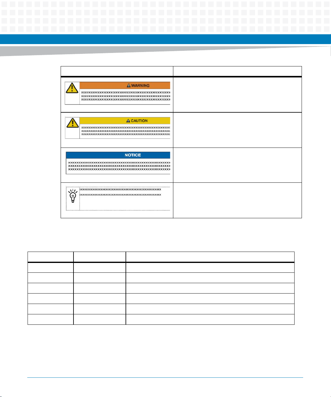
Notation Description
Indicates a hazardous situation which, if not avoided,
could result in death or serious injury
Indicates a hazardous situation which, if not avoided,
may result in minor or moderate injury
Indicates a property damage message
No danger encountered. Pay attention to important
information
About this Manual
Summary of Changes
Part Number Publication Date Description
6806800P15A May 2012 Initial Version
6806800P15B June 2012 Initial Version
6806800P15C October 2012 Updated Table 5-1 on page 129.
6806800P15D December 2012 GA Release
6806800P15E January 2013 Updated Table 2-6 on page 55.
6806800P15F February 2013 Updated Table 2-3 on page 50.
ATCA-7470 Installation and Use (6806800P15K)
23
Page 24

About this Manual
About this Manual
Part Number Publication Date Description
6806800P15G January 2014 Updated Table "Environmental Requirements" on page 47. Added a
new chapter Chapter 8, Boot Bank Selection, Updated section Artesyn
Specific Commands on page 225, and Updated sections EMC on page
25 and EMV on page 30.
6806800P15H January 2014 Updated Table "Blade Variants" on page 42, Table "Critical Temperature
Limits" on page 49 and Table "Power Requirements" on page 50.
Updated Processor on page 124.
6806800P15J May 2014 Re-branded to Artesyn.
6806800P15K October 2014 Updated Figure "Serial Number Location" on page 41, Figure "ATCA-
7470 Blade Layout" on page 52, Figure "Face Plate" on page 67, Figure
"Location of MO297 SSD Module Connector" on page 73, Figure
"Location of AdvancedTCA Connectors" on page 75, and Figure
"Location of Temperature Sensors" on page 261 with ELMA variant
figures.
Updated the installation and removal steps in Installing and Removing
the Blade on page 61 as per ELMA variant handle usage.
24
ATCA-7470 Installation and Use (6806800P15K)
Page 25

Safety Notes
This section provides warnings that precede potentially dangerous procedures throughout
this manual. Instructions contained in the warnings must be followed during all phases of
operation, service, and repair of this equipment. You should also employ all other safety
precautions necessary for the operation of the equipment in your operating environment.
Failure to comply with these precautions or with specific warnings elsewhere in this manual
could result in personal injury or damage to the equipment.
Artesyn Embedded Technologies intends to provide all necessary information to install and
handle the product in this manual. Because of the complexity of this product and its various
uses, we do not guarantee that the given information is complete. If you need additional
information, ask your Artesyn representative.
The product has been designed to meet the standard industrial safety requirements. It must
not be used except in its specific area of office telecommunication industry and industrial
control.
Only personnel trained by Artesyn or persons qualified in electronics or electrical engineering
are authorized to install, remove or maintain the product.
The information given in this manual is meant to complete the knowledge of a specialist and
must not be used as replacement for qualified personnel.
Keep away from live circuits inside the equipment. Operating personnel must not remove
equipment covers. Only factory authorized service personnel or other qualified service
personnel may remove equipment covers for internal subassembly or component replacement
or any internal adjustment.
Do not install substitute parts or perform any unauthorized modification of the equipment or
the warranty may be voided. Contact your local Artesyn representative for service and repair
to make sure that all safety features are maintained.
EMC
The blade has been tested in a standard Artesyn system and found to comply with the limits
for a Class A digital device in this system, pursuant to part 15 of the FCC Rules, EN 55022 Class
A respectively. These limits are designed to provide reasonable protection against harmful
interference when the system is operated in a commercial environment.
ATCA-7470 Installation and Use (6806800P15K)
25
Page 26

This is a Class A product based on the standard of the Voluntary Control Council for
Interference by Information Technology Interference (VCCI). If this equipment is used in a
domestic environment, radio disturbance may arise. When such trouble occurs, the user may
be required to take corrective actions.
The blade generates and uses radio frequency energy and, if not installed properly and used in
accordance with this guide, may cause harmful interference to radio communications.
Operating the system in a residential area is likely to cause harmful interference, in which case
the user will be required to correct the interference at his own expense.
The COM1, ETH1, ETH2, USB1 and USB2 interfaces are considered as debug/maintenance
ports. During normal operation no cables must be connected to these ports. Cables attached
to these ports during maintenance must not exceed a length of 3m.
Installation
Safety Notes
Damage of Circuits
Electrostatic discharge and incorrect blade installation and removal can damage circuits or
shorten their life.
Before touching the blade or electronic components, make sure that you are working in an
ESD-safe environment.
Data Loss
Removing the blade with the blue LED still blinking causes data loss.
Wait until the blue LED is permanently illuminated, before removing the blade.
Damage of Blade and Additional Devices and Modules
Incorrect installation of additional devices or modules may damage the blade or the additional
devices or modules.
Before installing or removing an additional device or module, read the respective
documentation
26
ATCA-7470 Installation and Use (6806800P15K)
Page 27

Safety Notes
System Damage
The intra building port(s) of the equipment or subassembly is suitable for connection to intra
building wiring or cabling only (Type 2 or Type 4 ports as described in GR-1089- CORE, Issue 4)
and require isolation from the exposed OSP (Outside Plant) cabling.The addition of primary
protectors is not sufficient protection in order to connect these interfaces metallically to OSP
wiring.
The intra building port(s) of the equipment or subassembly must not be metallically
connected to interfaces that connect to the OSP or its wiring.
Operation
Ensure that the display devices that are permanently connected to the VGA interface provide
a fire enclosure according to the IEC/EN/UL/CSA 60950-1 requirements.
All other devices that are connected only for service purposes to the VGA interface needs
supervision during operation and must be disconnected after maintenance.
Blade Damage
Blade surface
High humidity and condensation on the blade surface causes short circuits.
Do not operate the blade outside the specified environmental limits. Make sure the blade is
completely dry and there is no moisture on any surface before applying power.
Blade Overheating and Blade Damage
Operating the blade without forced air cooling may lead to blade overheating and thus blade
damage.
When operating the blade, make sure that forced air cooling is available in the shelf.
When operating the blade in areas of electromagnetic radiation ensure that the blade is bolted
on the system and the system is shielded by enclosure.
Injuries or Short Circuits
Blade or power supply
ATCA-7470 Installation and Use (6806800P15K)
27
Page 28

In case the O-Ring diodes of the blade fail, the blade may trigger a short circuit between input
line A and input line B so that line A remains powered even if it is disconnected from the power
supply circuit (and vice versa).
To avoid damage or injuries, always check that there is no more voltage on the line that has
been disconnected before continuing your work.
Switch Settings
Blade Malfunction
Switches marked as 'reserved' might carry production-related functions and can cause the
blade to malfunction if their setting is changed.
Therefore, do not change settings of switches marked as 'reserved'. The setting of switches
which are not marked as 'reserved' has to be checked and changed before blade installation.
Safety Notes
Blade Damage
Setting/resetting the switches during operation can cause blade damage.
Therefore, check and change switch settings before you install the blade.
Battery
Blade Damage
Wrong battery installation may result in hazardous explosion and blade damage.
Therefore, always use the same type of Lithium battery as is installed and make sure the
battery is installed as described in this manual.
Environment
Always dispose of used blades, system components and RTMs according to your country’s
legislation and manufacturer’s instructions.
28
ATCA-7470 Installation and Use (6806800P15K)
Page 29

Sicherheitshinweise
Dieses Kapitel enthält Hinweise, die potentiell gefährlichen Prozeduren innerhalb dieses
Handbuchs vorrangestellt sind. Beachten Sie unbedingt in allen Phasen des Betriebs, der
Wartung und der Reparatur des Systems die Anweisungen, die diesen Hinweisen enthalten
sind. Sie sollten außerdem alle anderen Vorsichtsmaßnahmen treffen, die für den Betrieb des
Produktes innerhalb Ihrer Betriebsumgebung notwendig sind. Wenn Sie diese
Vorsichtsmaßnahmen oder Sicherheitshinweise, die an anderer Stelle diese Handbuchs
enthalten sind, nicht beachten, kann das Verletzungen oder Schäden am Produkt zur Folge
haben.
Artesyn Embedded Technologies ist darauf bedacht, alle notwendigen Informationen zum
Einbau und zum Umgang mit dem Produkt in diesem Handbuch bereit zu stellen. Da es sich
jedoch um ein komplexes Produkt mit vielfältigen Einsatzmöglichkeiten handelt, können wir
die Vollständigkeit der im Handbuch enthaltenen Informationen nicht garantieren. Falls Sie
weitere Informationen benötigen sollten, wenden Sie sich bitte an die für Sie zuständige
Geschäftsstelle von Artesyn.
Das System erfüllt die für die Industrie geforderten Sicherheitsvorschriften und darf
ausschließlich für Anwendungen in der Telekommunikationsindustrie und im Zusammenhang
mit Industriesteuerungen verwendet werden.
Einbau, Wartung und Betrieb dürfen nur von durch Artesyn ausgebildetem oder im Bereich
Elektronik oder Elektrotechnik qualifiziertem Personal durchgeführt werden. Die in diesem
Handbuch enthaltenen Informationen dienen ausschließlich dazu, das Wissen von
Fachpersonal zu ergänzen, können dieses jedoch nicht ersetzen.
Halten Sie sich von stromführenden Leitungen innerhalb des Produktes fern. Entfernen Sie auf
keinen Fall Abdeckungen am Produkt. Nur werksseitig zugelassenes Wartungspersonal oder
anderweitig qualifiziertes Wartungspersonal darf Abdeckungen entfernen, um Komponenten
zu ersetzen oder andere Anpassungen vorzunehmen.
Installieren Sie keine Ersatzteile oder führen Sie keine unerlaubten Veränderungen am Produkt
durch, sonst verfällt die Garantie. Wenden Sie sich für Wartung oder Reparatur bitte an die für
Sie zuständige Geschäftsstelle von Artesyn. So stellen Sie sicher, dass alle
sicherheitsrelevanten Aspekte beachtet werden.
ATCA-7470 Installation and Use (6806800P15K)
29
Page 30

EMV
Sicherheitshinweise
Das Blade wurde in einem Artesyn Standardsystem getestet. Es erfüllt die für digitale Geräte
der Klasse A gültigen Grenzwerte in einem solchen System gemäß den FCC-Richtlinien
Abschnitt 15 bzw. EN 55022 Klasse A. Diese Grenzwerte sollen einen angemessenen Schutz
vor Störstrahlung beim Betrieb des Blades in Gewerbe- sowie Industriegebieten
gewährleisten.
Das Blade arbeitet im Hochfrequenzbereich und erzeugt Störstrahlung. Bei unsachgemäßem
Einbau und anderem als in diesem Handbuch beschriebenen Betrieb können Störungen im
Hochfrequenzbereich auftreten.
Warnung! Dies ist eine Einrichtung der Klasse A. Diese Einrichtung kann im Wohnbereich
Funkstörungen verursachen. In diesem Fall kann vom Betreiber verlangt werden,
angemessene Maßnahmen durchzuführen.
Die nachfolgend aufgeführten Schnittstellen sind Wartungsschnittstellen: COM1, ETH1,
ETH2, USB1, USB2. Während des Normalbetriebs darf an diesen Schnittstellen kein Kabel
angeschlossen sein.Im Wartungsfall angeschlossene Kabel dürfen eine Länge von 3m nicht
überschreiten.
Installation
Beschädigung von Schaltkreisen
Elektrostatische Entladung und unsachgemäßer Ein- und Ausbau von Blades kann Schaltkreise
beschädigen oder ihre Lebensdauer verkürzen.
Bevor Sie Blades oder elektronische Komponenten berühren, vergewissern Sie sich, daß Sie in
einem ESD-geschützten Bereich arbeiten.
Datenverlust
Wenn Sie das Blade aus dem Shelf herausziehen, und die blaue LED blinkt noch, gehen Daten
verloren.
Warten Sie bis die blaue LED durchgehend leuchtet, bevor Sie das Blade herausziehen.
30
ATCA-7470 Installation and Use (6806800P15K)
Page 31

Beschädigung des Blades und von Zusatzmodulen
Fehlerhafte Installation von Zusatzmodulen, kann zur Beschädigung des Blades und der
Zusatzmodule führen.
Lesen Sie daher vor der Installation von Zusatzmodulen die zugehörige Dokumentation.
Beschädigung des Systems
Die Gebäude-internen Schnittstellen ("intra-building ports" per GR-1089-CORE) der Geräte
oder Baugruppen sind nur für gebäudeinterne Verkabelung vorgesehen. Die Schnittstellen
sind als Typ 2 oder Typ 4 definiert (wie in GR-1089-Core beschrieben) und erfordern eine
Isolation zu Leitungen außerhalb des Gebäudes.
Die Gebäude-internen Schnittstellen dürfen keine elektrisch leitende Verbindung zu Leitungen
außerhalb des Gebäudes haben. Ein "Primary Protector" (wie in GR-1089-CORE beschrieben)
ist keine ausreichende Absicherung, um die Gebäude-internen Schnittstellen mit Leitungen
außerhalb des Gebäudes zu verbinden.
Sicherheitshinweise
Betrieb
Stellen Sie sicher, daß Geräte, die dauerhaft mit der VGA Schnittstelle verbunden, sind über ein
Brandschutzgehäuse verfügen, die die Anforderungen der IEC/EN/UL/CSA 60950-1 Norm
erfüllen.
Alle anderen Geräte, die nur zeitweise für Wartungsarbeiten an die VGA Schnittstelle
angeschlossen werden, müssen während dem Betrieb überwacht und nach der Beendigung
der Wartungsarbeiten entfernt werden.
Beschädigung des Blades
Hohe Luftfeuchtigkeit und Kondensat auf der Oberfläche des Blades können zu Kurzschlüssen
führen.
Betreiben Sie das Blade nur innerhalb der angegebenen Grenzwerte für die relative
Luftfeuchtigkeit und Temperatur. Stellen Sie vor dem Einschalten des Stroms sicher, dass sich
auf dem Blade kein Kondensat befindet.
ATCA-7470 Installation and Use (6806800P15K)
31
Page 32

Überhitzung und Beschädigung des Blades
Betreiben Sie das Blade ohne Zwangsbelüftung, kann das Blade überhitzt und schließlich
beschädigt werden.
Bevor Sie das Blade betreiben, müssen Sie sicher stellen, dass das Shelf über eine
Zwangskühlung verfügt.
Wenn Sie das Blade in Gebieten mit starker elektromagnetischer Strahlung betreiben, stellen
Sie sicher, dass das Blade mit dem System verschraubt ist und das System durch ein Gehäuse
abgeschirmt wird.
Verletzungen oder Kurzschlüsse
Blade oder Stromversorgung
Falls die ORing Dioden des Blades durchbrennen, kann das Blade einen Kurzschluss zwischen
den Eingangsleitungen A und B verursachen. In diesem Fall ist Leitung A immer noch unter
Spannung, auch wenn sie vom Versorgungskreislauf getrennt ist (und umgekehrt).
Prüfen Sie deshalb immer, ob die Leitung spannungsfrei ist, bevor Sie Ihre Arbeit fortsetzen,
um Schäden oder Verletzungen zu vermeiden.
Sicherheitshinweise
Schaltereinstellungen
Fehlfunktion des Blades
Schalter, die mit 'Reserved' gekennzeichnet sind, können mit produktionsrelevanten
Funktionen belegt sein. Das Ändern dieser Schalter kann im normalen Betrieb Störungen
auslösen.
Verstellen Sie nur solche Schalter, die nicht mit 'Reserved' gekennzeichnet sind. Prüfen und
ändern Sie die Einstellungen der nicht mit 'Reserved' gekennzeichneten Schalter, bevor Sie das
Blade installieren.
Beschädigung der Blade
Das Verstellen von Schaltern während des laufenden Betriebes kann zur Beschädigung des
Blades führen.
Prüfen und ändern Sie die Schaltereinstellungen, bevor Sie das Blade installieren.
32
ATCA-7470 Installation and Use (6806800P15K)
Page 33

Batterie
Beschädigung des Blades
Ein unsachgemäßer Einbau der Batterie kann gefährliche Explosionen und Beschädigungen
des Blades zur Folge haben.
Verwenden Sie deshalb nur den Batterietyp, der auch bereits eingesetzt wurde und befolgen
Sie die Installationsanleitung.
Umweltschutz
Entsorgen Sie alte Batterien und/oder Blades/Systemkomponenten/RTMs stets gemäß der in
Ihrem Land gültigen Gesetzgebung und den Empfehlungen des Herstellers.
Sicherheitshinweise
ATCA-7470 Installation and Use (6806800P15K)
33
Page 34

Sicherheitshinweise
34
ATCA-7470 Installation and Use (6806800P15K)
Page 35

Introduction
1.1 Features
The ATCA-7470 is a high-performance ATCA compliant single board computer designed for
demanding storage and processing applications.
The main features of the ATCA-7470 board are as follows:
Designed for NEBS level 3
Dual socket Intel Xeon E5-2600
Standard configuration ATCA-7470:
– Option 95W CPU Intel E5-2658 2100 MHz
– Intel Xeon E5-2648L 8-core 70W 1.8GHz
– DDR3 memory support up to 1600MHz
Chapter 1
– LVDDR3 (1.35V) support up to 1333MHz for better thermal performance and reduced
power consumption
– Four independent DDR3 memory channels per CPU with one DIMM slot per channel (1
DPC) resulting in a total of 8 DIMM slots
– 4GB, 8GB, and 16GB DDR3 modules in VLP available
Single slot ATCA form factor (280mm x 322mm)
Direct CPU to PCIe interface providing 40 PCIe Gen3 lanes (8 Gbps)
Next Generation Communications Platform from Intel, codename Crystal Forest with
onboard DH8900CC (SKU1) Platform controller I/O Hub (PCH)
Additional two Next Generation Communications Platform PCH devices via ATCA-7470
Acceleration Module DH8920CC (SKU4) (each PCH of x16 PCIe Gen2 attached) (optional)
Intel Quickassist Technology support for advanced Datapacket processing on onboard
PCH and on ACC-module
Dual Gb Ethernet AdvancedTCA Base Interfaces according to PICMG 3.0
Dual 40GBASE-KR4,10GBASE-KR,10GBASE-KX4,1000Base-KX: Option1, 1-K,1-KR,9,9-
K,9-KR Ethernet AdvancedTCA Fabric Interfaces according to PICMG 3.1
Dual GbE ports on Faceplate
Serial over LAN via AdvancedTCA base Interface
ATCA-7470 Installation and Use (6806800P15K)
35
Page 36

Introduction
CPU and I/O virtualization support
Power management support
Crisis recovery for BIOS, IPMC Firmware, and FPGA code
MO-297/SlimSATA module slot to carry 32, 64, or 128GB SSD module drive (optional)
36
ATCA-7470 Installation and Use (6806800P15K)
Page 37

1.2 Standard Compliances
The product is designed to meet the following standards.
Table 1-1 Standard Compliances
Standard Description
Introduction
UL 60950-1
EN 60950-1
IEC 60950-1
CAN/CSA C22.2 No 60950-1
CISPR 22
CISPR 24
EN 55022
EN 55024
FCC Part 15
EN 300386
NEBS Standard GR-1089 CORE
ISO 8601 Y2K compliance
NEBS Standard GR-63-CORE
ETSI EN 300019 series
PICMG 3.0 and 3.1 Defines mechanics, blade dimensions, power distribution,
1. The blade does not fulfill the “Unpacked Equipment Shock Criteria” as defined in NEBS GR63 4.3.2. During tests
which consisted of dropping the blade from 100 mm height, we observed that on some blades the AdvancedTCA zone
2 and 3 connectors got damaged. Although it was possible to manually repair the connectors and the blade was fully
functional again afterwards, the criteria imposed by the NEBS standard were not fulfilled.
1
Legal safety requirements
EMC requirements on system level (predefined Artesyn
Embedded Technologies system)
NEBS level three
Product is designed to support NEBS level three. The
compliance tests must be done with the customer target
system.
power and data connectors, and system management
ATCA-7470 Installation and Use (6806800P15K)
37
Page 38

Introduction
To fulfill the requirements of Telcordia GR-1089, R4-14, use Shielded Twisted Pair (STP)
This blade contains an embedded power source rated >150W. To achieve NEBS
The product has been designed to meet the directive on the restriction of the use of
cables grounded at both ends to connect to the Ethernet ports.
compliance on system level, Shelf Ground (chassis ground) and Logic Ground (logic
signal return) have to be connected. The connection may be implemented inside the
shelf, for example at the backplane, or the shelf has to provide a possibility to lead Logic
Ground out of the shelf for external connection to Central Office Ground. For further
information refer to Telcordia GR-1089-CORE, section 9.8.2, requirement R9-14.
certain hazardous substances in electrical and electronic equipment (RoHS) Directive
2002/95/EC.
38
ATCA-7470 Installation and Use (6806800P15K)
Page 39

The following figure contains the Declaration of Conformity for ATCA-7470.
Figure 1-1 Declaration of Conformity
Introduction
ATCA-7470 Installation and Use (6806800P15K)
39
Page 40

Introduction
1.3 Mechanical Data
The following table provides details about the mechanical data of the blade, such as
dimensions and weight.
Table 1-2 Mechanical Data
Feature Value
Dimensions (width x height x depth) 30 mm x 351 mm x 312 mm 8U form factor
Weight of blade 3.2 kg
40
ATCA-7470 Installation and Use (6806800P15K)
Page 41

1.4 Product Identification
The following figure shows the location of the serial number label.
Figure 1-2 Serial Number Location
Serial Number
Location
Introduction
ATCA-7470 Installation and Use (6806800P15K)
41
Page 42

Introduction
1.5 Ordering Information
The ATCA-7470 is a high performance ATCA compliant single board computer designed for
demanding storage and processing applications.
The following table lists the blade variants that are available upon release of this publication.
Consult your local Artesyn sales representative for the availability of other variants.
Table 1-3 Blade Variants
Product Name Description
ATCA-7470-0GB ATCA-7470 Blade with Dual Intel Xeon E5-2648L 8-Core @1.8GHz
processors (Sandy Bridge 70W TDP), 2.5MB per Core Last Level Cache,
256KB L2 Cache per core, 32Kb+32KB L1 Cache per core; no memory preinstalled.
ATCA-7470-32GB ATCA-7470 Blade with Dual Intel Xeon E5-2648L 8-Core @1.8GHz
processors (Sandy Bridge 70W TDP), 2.5MB per Core Last Level Cache,
256KB L2 Cache per core, 32Kb+32KB L1 Cache per core; 32 GB DDR31600 with 8x4GB DIMM pre-installed.
42
ATCA-7470-64GB ATCA-7470 Blade with Dual Intel Xeon E5-2648L 8-Core @1.8GHz
processors (Sandy Bridge 70W TDP), 2.5MB per Core Last Level Cache,
256KB L2 Cache per core, 32Kb+32KB L1 Cache per core; 64 GB DDR31600 with 8x8GB DIMM pre-installed.
ATCA-7470-0GB-CE ATCA-7470 Blade with Dual Intel Xeon E5-2658 8-Core @2.1GHz
processors (Sandy Bridge 95W TDP), 2.5MB per Core Last Level Cache,
256KB L2 Cache per core, 32Kb+32KB L1 Cache per core; no memory preinstalled.
The following table lists the blade accessories that are available upon release of this
publication. Consult your local sales representative for the availability of other accessories.
Table 1-4 Blade Accessories
Accessory Description
ATCA-7470-ACCEL-MOD HW acceleration module for the ATCA-7470 providing 2 high
performance Intel DH8920CC Cave Creek SKU4
encryption/decryption and packet processing engines
ATCA-7XMEM-1600-4G 4GB DDR3-1600 (PC3-12800) VLP memory module
ATCA-7470 Installation and Use (6806800P15K)
Page 43

Introduction
Table 1-4 Blade Accessories (continued)
Accessory Description
ATCA-7XMEM-1600-8G 8GB DDR3-1600 (PC3-12800) VLP memory module
ATCA-7XMEM-1600-16G 16GB DDR3-1600 (PC3-12800) VLP memory module
ATCA-7XMMOD-SATA1 32 GB SLC SLIM SATA (MO-297) on-board solid state disk module
ATCA-7XMMOD-SATA2 64 GB SLC SLIM SATA (MO-297) on-board solid state disk module
SA-BBS-WR43-7475 DVD - BBS SW and WindRiver Linux 4.3 for ATCA-7475
ATCA-7470 Installation and Use (6806800P15K)
43
Page 44

Introduction
44
ATCA-7470 Installation and Use (6806800P15K)
Page 45

Hardware Preparation and Installation
2.1 Unpacking and Inspecting the Blade
Damage of Circuits
Electrostatic discharge and incorrect blade installation and removal can damage circuits or
shorten their life.
Before touching the blade or electronic components, make sure that you are working in an
ESD-safe environment.
Shipment Inspection
Chapter 2
To inspect the shipment, perform the following steps.
1. Verify that you have received all items of your shipment:
ATCA-7470 blade
Any optional items ordered
2. Check for damage and report any damage or differences to the customer service.
3. Remove the desiccant bag shipped together with the blade and dispose of it
according to your country’s legislation.
The blade is thoroughly inspected before shipment. If any damage has occurred during
transportation or any items are missing, contact our customer's service immediately.
2.2 Environmental and Power Requirements
In order to meet the environmental requirements, the blade has to be tested in the system in
which it is to be installed.
ATCA-7470 Installation and Use (6806800P15K)
45
Page 46

Hardware Preparation and Installation
Before you power up the blade, calculate the power needed according to your combination of
blade upgrades and accessories.
2.2.1 Environmental Requirements
The environmental conditions must be tested and proven in the shelf configuration used. The
conditions refer to the surrounding of the blade within the user environment.
The environmental requirements of the blade may be further limited down due to
installed accessories, such as hard disks or PMC modules, with more restrictive
environmental requirements.
Operating temperatures refer to the temperature of the air circulating around the
blade and not to the actual component temperature.
46
Blade Damage
Blade Surface
High humidity and condensation on the blade surface causes short circuits.
Do not operate the blade outside the specified environmental limits. Make sure the blade is
completely dry and there is no moisture on any surface before applying power.
Blade Overheating and Blade Damage
Operating the blade without forced air cooling may lead to blade overheating and thus
blade damage.
When operating the blade, make sure that forced air cooling is available in the shelf.
ATCA-7470 Installation and Use (6806800P15K)
Page 47

Hardware Preparation and Installation
Table 2-1 Environmental Requirements
Requirement Operating Non-Operating
Temperature Normal Operation: +5 °C (41 °F) to +40
°C (104 °F) according to Telcordia GR63-CORE (NEBS) and ETSI EN 300 0191-3, Class 3.1
Exceptional Operation: -5 °C (23 °F) to
+55 °C (131 °F) according to Telcordia
GR-63-CORE (NEBS)
Note: This exceeds ETSI EN 300 019-13, Class 3.1E requirements (-5°C to
+45°C)
Temp. Change +/- 0.25 °C/min according to Telcordia
GR-63-CORE
Rel. Humidity Normal Operation: 5%rH to 85%rh non-
condensing
Exceptional Operation: 5%rH to 90%rh
non-condensing
According to Telcordia GR-63-CORE
(NEBS) and EN 300 019-1-3, Classes 3.1
and 3.1E
Vibration 1g from 5 to 200Hz and back to 5Hz at
a rate of 0.25 octave/minute
(according to Telcordia GR-63-core)
Shock Half-sine, 11 ms, 30 m/s
2
Free Fall - 1.2 m/ packaged (according to ETSI 300
-40 °C (-40 °F) to +70 °C (158 °F) according
to Telcordia GR-63-CORE (NEBS) and ETSI
EN 300 019-1-2, Class 2.3
Note: This exceeds ETSI EN 300 019-1-1,
Class 1.2 requirements (storage from 25 °C to +55 °C
Note: This may be further limited by
installed accessories.
+/- 0.25 °C/min
5% to 95% non-condensing according to
Telcordia GR-63-CORE (NEBS) and EN 300
019-1-1, Classes 1.2 and 2.3
5-20 Hz at 0.01 g
2
/Hz (according to
Telcordia GR-63-core and ETSI EN 300
019-2-2)
20-200 Hz at -3 dB/octave Hz (according
to Telcordia GR-63-core and ETSI EN 300
019-2-2)
Random 5-20Hz at 1 m
Random 20-200Hz at 3 m2/s
2/s3
3
Blade level packaging
Half-sine, 6 ms at 180 m/s
2
019-2-2)
100 mm unpackaged (according to
Telcordia GR-63-core)
ATCA-7470 Installation and Use (6806800P15K)
47
Page 48

Hardware Preparation and Installation
During the safety qualification of this blade, the following on-board locations were identified
as critical with regards to the maximum temperature during blade operation. To guarantee
proper blade operation and to ensure safety, you have to make sure that the temperatures at
the locations specified in the following are not exceeded. If not stated otherwise, the
temperatures should be measured by placing a sensor exactly at the given locations.
Figure 2-1 Location of Critical Temperature Spots (Blade Top Side)
48
Temperature Spot 2 (on 48 DC/DC Converter)
Max: 100°C , (exact location: in the geometric
middle of the heat spreader)
Temperature Spot 1 (on Power Entry Module)
Max: 110°C , (exact location: on top of upper
transformer housing)
ATCA-7470 Installation and Use (6806800P15K)
Page 49

Hardware Preparation and Installation
Table 2-2 Critical Temperature Limits
Component Thermal Design Power Max Case or Junction Temperature
All product variants except
ATCA-7470-xGB-CE:
Intel Xeon E5-2648L
ATCA-7470-xGB-CE
variant:
Intel Xeon E5-2658
Intel PCH DH8900CC 8.5W Tjmax 103°C
Intel PCH DH8920CC 9.2W Tjmax 103°C
Mellanox MT27514 5.5W Tjmax 105°C
DDR3 DIMM modules 6.9W Tcase_max 85°C
70W Tj.max ~100°C (CPU specific and readable
95W Tj.max ~100°C (CPU specific and readable
If you integrate the blade in your own system, contact your local sales representative for further
safety information.
2.2.2 Power Requirements
The blade's power requirements depend on the installed hardware accessories. If you want to
install accessories on the blade, the load of the respective accessory has to be added to that of
the blade. In the following table you will find typical examples of power requirements with and
without accessories installed. For information on the accessories' power requirements, refer to
the documentation delivered together with the respective accessory or consult your local
Artesyn representative for further details.
in TEMPERATURE_TARGET
register)
in TEMPERATURE_TARGET
register)
ATCA-7470 Installation and Use (6806800P15K)
49
Page 50

Hardware Preparation and Installation
The blade must be connected to a TNV-2 or a safety-extra-low-voltage (SELV) circuit. A TNV-2
circuit is a circuit whose normal operating voltages exceed the limits for a SELV circuit under
normal operating conditions, and which is not subject to overvoltages from
telecommunication networks.
Table 2-3 Power Requirements
Characteristic Value
Rated Voltage
Exception in the US and Canada
Operating Voltage
Exception in the US and Canada
Max. power consumption of ATCA-7470 (with ATCA7470-ACCEL-MOD and with RTM-ATCA-736x-10G
including SAS HDD)
Max. power consumption of ATCA-7470 (without
ATCA-7470-ACCEL-MOD and without RTM)
-48 VDC to -60 VDC
-48 VDC
-39 VDC to -72 VDC
-39 VDC to -60 VDC
All product variants except ATCA-7470xGB-CE: 250W (typ. 215W)
ATCA-7470-xGB-CE variant: 300W (typ.
265W)
All product variants except ATCA-7470xGB-CE: 210W (typ. 170W)
ATCA-7470-xGB-CE variant: 260W (typ.
220W)
50
ATCA-7470 Installation and Use (6806800P15K)
Page 51

Hardware Preparation and Installation
The blade provides two independent power inputs according to the AdvancedTCA
Specification. Each input has to be equipped with an additional fuse of max. 90 A located either
in the shelf where the blade is installed or the power entry module (PEM).
The power consumption has been measured using specific boards in a configuration
considered to represent the worst-case (with RTM-ATCA-7360 and SAS HDD, maximum
memory population, ATCA-7470-ACCEL-MOD module, ATCA-MO297 SSD module) and with
software simultaneously exercising as many functions and interfaces as possible. This
includes a particular load software provided by Intel designed to stress the processors to
reach their theoretical maximum power specification.
Any difference in the system configuration or the software executed by the processors may
affect the actual power dissipation. Depending on the actual operating configuration and
conditions, customers may see slightly higher power dissipation, or it may even be
significantly lower. There is also a dependency on the batch variance of the major
components like the processor and DIMMs used. Hence, Artesyn does not represent or
warrant that measurement results of a specific board provide guaranteed maximum values
for a series of boards.
ATCA-7470 Installation and Use (6806800P15K)
51
Page 52

Hardware Preparation and Installation
2.3 Blade Layout
The following figure shows the location of components on the ATCA-7470:
Figure 2-2 ATCA-7470 Blade Layout
J22 (DIMM6)
J21 (DIMM5)
ACC Module
Connectors
J14 (DIMM4)
J13 (DIMM3)
CPU 0
J23 (DIMM7)
J24 (DIMM8)
CPU 1
J12 (DIMM2)
J11 (DIMM1)
FAB 2
FAB 1
ZONE 1
ATCA PIMDCDC
Intel PCH
52
ATCA-7470 Installation and Use (6806800P15K)
Page 53

2.4 Switch Settings
All mechanical switches are OFF in their default configuration. Switch selection used only for
debugging are grouped in separate devices, which are not assembled in volume production.
Switches reside on the component side 1 and are not covered by any other component. Their
location is shown in the following figure:
Figure 2-3 Switch Location (Bottom Side of the Blade)
Hardware Preparation and Installation
ATCA-7470 Installation and Use (6806800P15K)
53
Page 54

Hardware Preparation and Installation
Table 2-4 Switch SW1 settings
Switch Function Default
SW1.1 Default SPI Boot Flash
Write protection
SW1.2 Recovery SPI Boot Flash
Write protection
SW1.3 TSOP or Debug-Socket
SPI Boot select
OFF= Boot from TSOP SPI
Flash (either
Default/Recovery)
ON = Boot from Debug
Socket SPI Flash
SW1.4 Reserved. Connected to
FPGA
OFF Not Write
Protected
OFF Not Write
Protected
OFF Boot from TSOP
SPI Flash
OFF Reserved
Table 2-5 Switch SW2 Settings
Switch Function Default
SW2.1 Serial Line #1 and #2 Routing
OFF FPGA-COM#1 to Faceplate
FPGA-COM#2 to RTM
ON FPGA-COM#1 to RTM
FPGA-COM#2 to Faceplate
SW2.2 SW2.2 IPMC Debug Console Routing
OFF IPMC Debug Console at 3-pin Header
ON IPMC Debug Console at Faceplate instead of
FPGA COM
OFF/OFF COM#1 and #2 (TTL-level)
routing
OFF: FPGA-COM#1 to
Face Plate and COM#2 to
RTM
OFF/OFF IPMC Debug Console
(TTL-level) routing
OFF:IPMC Debug Console
at 3-pin Header
54
SW2.3 FPGA_PROM_SEL
OFF = High => Use default FPGA EEPROM
ON = Low => Use Fail-Safe FPGA EEPROM
SW2.4 Reserved OFF
ATCA-7470 Installation and Use (6806800P15K)
OFF (1) Use standard download
PROM or redundant
download PROM for FPGA
configuration
Page 55

Hardware Preparation and Installation
Table 2-6 Switch SW3 Settings
Switch Function Default
SW3.1 manual “Default SPI Boot Flash” / “Recovery SPI
Boot Flash” select enable.
ON: SW3.2 selects Boot Flash
SW3.2 SW3.2 controls Boot flash select if SW3.1 is ON
OFF = Boot from “Default SPI Boot Flash” device
ON= Boot from “Recovery SPI Boot Flash” device
SW3.3 OFF = Face Plate Reset push button enabled
ON = Face Plate Reset push button disabled
SW3.4 OFF = Watchdog trigger enabled
ON = Watchdog trigger disabled (results in cyclic
IPMC Reset), available only in AUTO Power mode
SW100-1 = ON. Not available to customer
powering through IPMC.
OFF IPMI selects Boot Flash
OFF OFF = Boot from “Default
SPI Boot Flash” device
OFF OFF=Face Plate Reset
push button enabled
OFF IPMC Watchdog timer
trigger is disabled (only
for test purposes and
works only in AUTOPpower mode SW100-1
ON)
Table 2-7 Switch SW4 Settings
Switch Function Default
SW4.1 Reserved OFF Must be OFF
SW4.2 TCO reboot on sec timeout
OFF: enabled
ON disable reboot feature
OFF Connected to CCK NRBOOTS
bootstrap pin (no reboot
second try strap)
SW4.3 [SW4.4, SW4.3]
SW4.4 OFF
ATCA-7470 Installation and Use (6806800P15K)
00 - Normal operation
01 - Reserved
10 - Load BIOS Defaults
11 - Port80 to COM1
OFF The Default is 00 - Normal
operation
55
Page 56

Hardware Preparation and Installation
2.5 Installing the Blade Accessories
The following additional components are available for the blade:
Dual Inline Memory Module (DIMM)
MO297 SSD Module
Rear transition modules
ATCA-7470 Accelerator Module
They are described in detail in the following sections. For order numbers, refer to section
Ordering Information on page 42.
2.5.1 DIMM Memory Modules
The blade provides up to 8 memory slots for main memory DIMM modules. You may install
and/or remove DIMM memory modules in order to match the main memory size to your
needs. The corresponding installation/removal procedures are described in this section.
56
The location of the DIMM Memory Modules are shown in Figure "ATCA-7470 Blade Layout" on
page 52.
When installing DIMM memory modules, the DIMM sockets farthest away on each memory
channel from the CPU device need to be populated first. Only qualified DDR3 DIMMs (Dual
Ranked RDIMM) are allowed. The reason is the thermal limit/budget of the blade and the high
variation of the power consumptions of different DIMM types. For thermal reasons, no 4-rank
DIMMs and no dual-Die DIMM are allowed.
ATCA-7470 supports low-voltage DDR3 memory. This is available upon request.
ATCA-7470 Installation and Use (6806800P15K)
Page 57

Hardware Preparation and Installation
ATCA-7470 has 1 DIMM socket per Xeon memory channel. Therefore usage of 2-rank DIMMs
are essential for best performance.
Damage of Circuits
Electrostatic discharge and incorrect module installation and removal can damage circuits
or shorten their life.
Before touching the module or electronic components, make sure that you are working in
an ESD-safe environment.
Installation Procedure
To install a DIMM module, proceed as follows:
1. Remove blade from system as described in Installing and Removing the Blade on
page 61.
2. Open locks of memory module socket.
3. Press module carefully into socket.
As soon as the memory module has been fully inserted, the locks automatically
close.
4. If applicable, repeat steps 2 to 3 to install further modules.
Damage of Circuits
Electrostatic discharge and incorrect module installation and removal can damage circuits
or shorten their life.
Before touching the module or electronic components, make sure that you are working in
an ESD-safe environment.
ATCA-7470 Installation and Use (6806800P15K)
57
Page 58

Hardware Preparation and Installation
Removal Procedure
To remove a DIMM module, proceed as follows:
1. Remove blade from system as described in Installing and Removing the Blade on
page 61.
2. Open locks of socket at both sides.
The memory module is automatically lifted up.
3. Remove module from socket.
4. Repeat steps 2 to 3 in order to remove further memory modules.
2.5.2 MO297 SSD Module
The SATA module consists of a Solid State Disc of up to 256 GB and a SATA controller and
connects physically to PCH Sata Port #4.
58
The MO297 SSD module is an accessory kit and is not part of the default ATCA-7470. The
following procedure describes the steps to install/remove the MO297 SSD module.
Installation Procedure
To install an MO297 SSD module, proceed as follows:
Damage of Circuits
Electrostatic discharge and incorrect module installation and removal can damage circuits
or shorten their life.
Before touching the module or electronic components, make sure that you are working in
an ESD-safe environment.
ATCA-7470 Installation and Use (6806800P15K)
Page 59

Hardware Preparation and Installation
1. Remove the blade from the system as described in Installing and Removing the Blade
on page 61.
2. Plug the MO297 SSD module into the MO297 connector. When inserting the
MO297 module to the onboard connector, hold the onboard connector with two
fingers to prevent damage to the connector.
3. Fasten the MO297 SSD module to the blade using the screws supplied with the ACC
kit.
4. Reinstall the blade into the system as described in Installing and Removing the Blade
on page 61.
The additional resource (either memory or SATA SSD) will be detected
automatically during the boot-up sequence.
Removal Procedure
To remove an MO297 SSD module, proceed as follows:
Damage of Circuits
Electrostatic discharge and incorrect module installation and removal can damage circuits
or shorten their life.
Before touching the module or electronic components, make sure that you are working in
an ESD-safe environment.
1. Remove the blade from the system as described in Installing and Removing the Blade
on page 61.
2. Remove the two screws holding the
3. Remove the
MO297 SSD module from the blade.
MO297 SSD module.
4. Reinstall the blade into the system as described in Installing and Removing the Blade
on page 61.
ATCA-7470 Installation and Use (6806800P15K)
59
Page 60

Hardware Preparation and Installation
2.5.3 Accelerator Module
The ATCA-7470 provides the possibility to assemble the ATCA-7470-Accelerator module. The
ATCA-7470-Accelerator module is equipped with two additional Intel DH8920CC SKU4 PCH
devices.
Installation Procedure
Damage of Circuits
Electrostatic discharge and incorrect module installation and removal can damage circuits
or shorten their life.
Before touching the module or electronic components, make sure that you are working in
an ESD-safe environment.
To install the accelerator module:
1. Remove the blade from the system.
2. Insert the Accelerator module in the socket so that the module's standoffs fit in the blade's
mounting holes.
3. Fasten the Accelerator module to the blade using the three M2.5x 8mm screws.
4. Reinstall the blade into the system.
Removal Procedure
Damage of Circuits
Electrostatic discharge and incorrect module installation and removal can damage circuits
or shorten their life.
Before touching the module or electronic components, make sure that you are working in
an ESD-safe environment.
60
ATCA-7470 Installation and Use (6806800P15K)
Page 61

Hardware Preparation and Installation
To remove the accelerator module:
1. Remove the blade from the system.
2.
Remove the three screws of the ACC-module from the bottom side (three Holes in Bottom
side cover).
3. Remove the Accelerator Module with Standoffs from the Blade.
4. Reinstall the blade into the system.
2.6 Installing and Removing the Blade
The blade is fully compatible to the AdvancedTCA standard and is designed to be used in
AdvancedTCA shelves.
The blade can be installed in any AdvancedTCA node slot. Do not install it in an AdvancedTCA
hub slot.
Damage of Circuits
Electrostatic discharge and incorrect blade installation and removal can damage circuits or
shorten their life.
Before touching the blade or electronic components, make sure that you are working in an
ESD-safe environment.
Blade Malfunctioning
Incorrect blade installation and removal can result in blade malfunctioning.
When plugging the blade in or removing it, do not press on the face plate but use the
handles.
2.6.1 Installing the Blade
The following procedure describes the installation of the blade. It assumes that your system is
powered on. If your system is not powered on, you can disregard the blue LED and skip the
respective step. In this case, it is purely a mechanical installation.
ATCA-7470 Installation and Use (6806800P15K)
61
Page 62

Hardware Preparation and Installation
Installation Procedure
To install the blade into an AdvancedTCA shelf, proceed as follows.
1. Visually inspect the blade and backplane connectors for damage or bent pins before
attempting to insert a board. If any connector damage or pin damage in observed, stop
before inserting the blade and send the damaged item through proper repair channels.
Latch
Handle
62
2. Slide the latch into the release position and pull out the handle outward to unlatch the
handle from the face plate. Do not rotate the handle fully outward.
ATCA-7470 Installation and Use (6806800P15K)
Page 63

Hardware Preparation and Installation
3. Insert blade into the shelf by placing the top and bottom edges of the blade in the card
guides of the shelf. Make sure that the guiding module of shelf and blade are aligned
properly.
4. Apply equal and steady pressure to the blade to carefully slide the blade into the shelf until
you feel resistance. Continue to gently push the blade until the blade connectors engage.
5. Fully insert the blade and turn the handle towards the face plate. The latch automatically
slides inwards and locks the handle.
If you feel that you need an abnormal amount of force during blade insertion to insert the
blade into the slot, please extract the blade, then carefully inspect the blade and slot for
problems to prevent damage.
If your shelf is powered, as soon as the blade is connected to the backplane power pins, the
blue LED is illuminated.
ATCA-7470 Installation and Use (6806800P15K)
63
Page 64

Hardware Preparation and Installation
When the blade is completely installed, the blue LED starts to blink. This indicates that the
blade has announced its presence to the shelf management controller.
If an RTM is connected to the front blade, make sure that the handles of both the RTM and the
front blade are closed in order to power up the blade’s payload.
6. Wait until the blue LED is switched off, then tighten the face plate screws which secure the
blade to the shelf. When the blue LED is switched OFF and the green LED shows "IS" (in
service) is switched ON, this indicates that the payload has been powered up and that the
blade is active.
7. Connect cables to the face plate, if applicable.
2.6.2 Removing the Blade
This section describes how to remove the blade from an AdvancedTCA system.
Damage of Circuits
Electrostatic discharge and incorrect blade installation and removal can damage circuits or
shorten their life.
Before touching the blade or electronic components, make sure that you are working in an
ESD-safe environment.
Blade Malfunctioning
Incorrect blade installation and removal can result in blade malfunctioning.
When plugging the blade in or removing it, do not press on the face plate but use the
handles.
64
ATCA-7470 Installation and Use (6806800P15K)
Page 65

Hardware Preparation and Installation
Removal Procedure
The following procedure describes how to remove the blade from a system. It assumes that the
system is powered on. If the system is not powered on, you can disregard the blue LED and skip
the respective step. In that case, it is purely a mechanical procedure.
1. Unlatch the handle from the face plate by sliding the latch into the release position
and pull out the handle outward. Do not rotate the handle fully outward. The blue
LED blinks indicating that the blade power-down process is ongoing.
The blue LED blinks indicating that the blade power-down process is going on.
2. Wait until the blue LED is illuminated permanently. Unfasten the screws of the
faceplate, then unlatch the handle and rotate the handle fully outward until the
blade is detached from the shelf.
If the LED continues to blink, a possible reason may be that the upper layer software has
rejected the blade extraction request.
Data Loss
Removing the blade with the blue LED still blinking causes data loss.
Wait until the blue LED is permanently illuminated, before removing the blade.
3. Remove the face plate cables, if applicable.
4. Unfasten the screws of the face plate until the blade is detached from the shelf.
5. Remove the blade from the shelf.
ATCA-7470 Installation and Use (6806800P15K)
65
Page 66

Hardware Preparation and Installation
66
ATCA-7470 Installation and Use (6806800P15K)
Page 67

Controls, Indicators, and Connectors
3.1 Face Plate
The following figure illustrates the connectors, keys, and LEDs available at the face plate:
Figure 3-1 Face Plate
TM
ARTESYN
R
E
S
E
T
C
O
M
1
I
S
E
T
A
H
T
1
N
E
T
H
2
Chapter 3
USB1
USB2
U1U2U3
H
/
S
ATCA-7470
ATCA-7470 Installation and Use (6806800P15K)
67
Page 68

Controls, Indicators, and Connectors
3.1.1 LEDs
The LEDs on the faceplate is described in the following table:
Table 3-1 Face Plate LEDs
LED Description
OOS Out Of Service
Red/optional Amber (controllable by IPMC): This LED is controlled by higher
layer software, such as middle ware or applications.
IS Payload Power Status
Green: The payload power has been enabled by the IPMC. Note that this LED
indicates the payload power status both in the early power state and the
normal blade operation.
OFF: Payload power is disabled
Note: This LED is multicolored (red/green/yellow) and is programmable by
IPMC.
68
ATN Amber: This LED is controlled by higher layer software, such as middle ware or
applications.
ETH Status LEDs The Ethernet connector provides two status LEDs
Link (upper)
Green: Link is available
Off: No link
Activity (lower)
Yellow: Activity
Off: No activity
U1, U2 Base interface activity is visualized via FPGA LEDs U1 and U2
U3 User LED, selectable color via FPGA register.
Colors: red, green, amber
ATCA-7470 Installation and Use (6806800P15K)
Page 69

Table 3-1 Face Plate LEDs (continued)
LED Description
H/S FRU State Machine
3.1.2 Keys
The blade provides one face plate reset key.
Controls, Indicators, and Connectors
During blade installation:
Permanently blue: On-board IPMC powers up
Blinking blue: Blade communicates with shelf manager
OFF: Blade is active
During blade removal:
Blinking blue: Blade notifies shelf manager of its desire to deactivate
Permanently blue: Blade is ready to be extracted
On pressing it, a hard reset is triggered and all attached on-board devices are reset.
You cannot reset the IPMC via this key.
3.1.3 Connectors
The blade provides the following connectors at its face plate:
2x Ethernet
1x Serial
2x USB
ATCA-7470 Installation and Use (6806800P15K)
69
Page 70

Controls, Indicators, and Connectors
3.1.3.1 Serial COM#1 P17
Serial line interface #1 of Glue Logic FPGA is available at the faceplate of ATCA-7470. A female
RJ45 connector is used for serial line connection. Cisco-like Pinout according following table is
used. Additionally, Hardware Handshake support signals are available.
Table 3-2 RJ45 female Serial Line Connector pinout
Pin Signal
1 COM1_CTS
2 COM1_DTR
3 COM1_RS232_TXD
4GND
5GND
6 COM1_RS232_RXD
7 COM1_DSR
8 COM1_RTS
3.1.3.2 Ethernet Connector
There are two Ethernet connectors:
ETH1 connector P70
ETH2 connector P71
70
ATCA-7470 Installation and Use (6806800P15K)
Page 71

The pinout of the connector is as follows.
Figure 3-2 Ethernet Interface Connectors Pinout
3.1.3.3 Serial Interface Connector
Controls, Indicators, and Connectors
The blade provides one RS-232 serial interface connector at its face plate. It is of type RJ-45 and
corresponds to the physical serial interface port 1. By default, the BIOS maps this interface to
the serial interface COM1. The on-board switch 2-1 allows to swap COM1 with COM2, making
COM2 accessible through the face plate connector instead. Note that the BIOS serial
redirection feature uses COM1 as access interface. Therefore swapping the serial interfaces via
SW2-1 also changes the serial connector that you need to access to make use of the serial
redirection feature.
The pinout of the serial interface connector is shown below.
Figure 3-3 Serial Interface Connector Pinout
ATCA-7470 Installation and Use (6806800P15K)
71
Page 72

Controls, Indicators, and Connectors
3.1.3.4 USB Connectors
The blade provides two USB connectors at its face plate. They are compliant to the USB 2.0
standard and correspond to the blade's USB interfaces 3 and 4.
The pinout of each USB connector is given in the following.
Figure 3-4 USB Connector Pinout
Attaching a device to the front panel USB ports that exceeds the maximum USB current rating
of 500mA per port will result in the ATCA-7470 protecting itself through a controlled board
shutdown.
3.2 On-board Connectors
The blade provides the following on-board connectors:
MO297 SSD module connector
ACC-module connector
3.2.1 MO297 SSD Module Connector
The MO297 SSD module connects to the blade through a connector that carries the following
types of signals:
1 SATA port (PCH port #4)
Power supply 5V and 3.3V
72
ATCA-7470 Installation and Use (6806800P15K)
Page 73

Controls, Indicators, and Connectors
The location of the MO297 SSD module connector is illustrated in the following figure.
Figure 3-5 Location of MO297 SSD Module Connector
ATCA-7470 Installation and Use (6806800P15K)
MO297 SSD
Module Connector
73
Page 74

Controls, Indicators, and Connectors
The pinout of this connector is illustrated in the following figure.
Figure 3-6 MO297 SSD Module Connector Pinout
SATA_TX+ S2
SATA_TX- S3
SATA_RX+ S6
SATA_RX- S5
GND S1,S4,S7
P4,P5,P6,P10,P12
+3.3V P1,P2,P3
+5V P7,P8,P9
+12V P13,P14,P15
3.3 AdvancedTCA Backplane Connectors
The AdvancedTCA backplane connectors reside in the three zones 1 to 3 as specified by the
AdvancedTCA standard, and are called P10, P20 and P23, P30, P31 and P32. The pinouts of all
these connectors are given in this section.
74
ATCA-7470 Installation and Use (6806800P15K)
Page 75

Controls, Indicators, and Connectors
Figure 3-7 Location of AdvancedTCA Connectors
P30
P31
P32
P20
The connector residing in zone 1 is called P10 and carries the following signals:
Power feed for the blade (VM48_x_CON and RTN_x_CON)
Power enable (ENABLE_x)
IPMB bus signals (IPMB0_x_yyy)
ATCA-7470 Installation and Use (6806800P15K)
P23
P10
75
Page 76

Controls, Indicators, and Connectors
Geographic address signals (HAx)
Ground signals (SHELF_GND and GND)
Reserved signals
Figure 3-8 P10 Backplane Connector Pinout
76
Zone 2 contains the two connectors P20 and P23. They carry the following types of signals:
Telecom clock signals (CLKx_)
Base interface signals (BASE_)
SAS update channel
100Base-BX update channel
ATCA-7470 Installation and Use (6806800P15K)
Page 77

Controls, Indicators, and Connectors
Some of the pins provided by P20 and P23 are defined as optional in the AdvancedTCA
specification and are unused on the blade. If the AdvancedTCA specification defines these
signals as input signals, they are terminated on the blade and marked as “TERM_” in the
following pinouts. In all other cases the pins are unconnected and consequently marked as
"n.c."
The pinouts of P20 and P23 are as follows.
Figure 3-9 P20 Backplane Connector Pinout - Rows A to D
Figure 3-10 P20 Backplane Connector Pinout - Rows E to H
ATCA-7470 Installation and Use (6806800P15K)
77
Page 78

Controls, Indicators, and Connectors
Figure 3-11 P23 Backplane Connector Pinout - Rows A to D
Figure 3-12 P23 Backplane Connector Pinout - Rows E to H
78
Zone 3 contains the two connectors P30, P31, and P32. They are used to connect an RTM to
the blade and carry the following signals:
Serial (RS232_x_yyyy)
Serial ATA (SATAx_yyy)
USB (USBxy)
PCI Express (PCIEx_yyy)
ATCA-7470 Installation and Use (6806800P15K)
Page 79

Controls, Indicators, and Connectors
IPMI (IPMB1_xxx, ISMB_xxx)
Power (VP12_RTM, V3P3_RTM, VP5_RTM)
SAS Update channels
General control signals (BD_PRESENTx, RTM_PRSNT_N, RTM_RST_KEY-, RTM_RST-)
Figure 3-13 P30 Backplane Connector Pinout - Rows A to D
Figure 3-14 P30 Backplane Connector Pinout - Rows E to H
ATCA-7470 Installation and Use (6806800P15K)
79
Page 80

Controls, Indicators, and Connectors
Figure 3-15 P31 Backplane Connector Pinout - Rows A to D
a
PCIE_CPU1_P3_RX_P<0>
1
PCIE_CPU1_P3_RX_P<2>
2
PCIE_CPU1_P3_RX_P<4>
3
PCIE_CPU1_P3_RX_P<6>
4
PCIE_CPU1_P3_RX_P<8>
5
PCIE_CPU1_P3_RX_P<10>
6
PCIE_CPU1_P3_RX_P<12>
7
PCIE_CPU1_P3_RX_P<14>
8
CLK100_RTM CPU1PORT3AB DP
9
n.c
10
b
PCIE_CPU1_P3_RX_N<0>
PCIE_CPU1_P3_RX_N<2>
PCIE_CPU1_P3_RX_N<4>
PCIE_CPU1_P3_RX_N<6>
PCIE_CPU1_P3_RX_N<8>
PCIE_CPU1_P3_RX_N<10>
PCIE_CPU1_P3_RX_N<12>
PCIE_CPU1_P3_RX_N<14>
CLK100_RTM CPU1PORT3AB DN
n.c
a b c d e f g h
c
PCIE_CPU1_P3_TX_P<0>
PCIE_CPU1_P3_TX_P<2>
PCIE_CPU1_P3_TX_P<4>
PCIE_CPU1_P3_TX_P<6>
PCIE_CPU1_P3_TX_P<8>
PCIE_CPU1_P3_TX_P<10>
PCIE_CPU1_P3_TX_P<12>
PCIE_CPU1_P3_TX_P<14>
CLK100_RTM CPU1PORT3CD DP
n.c.
Figure 3-16 P31 Backplane Connector Pinout - Rows E to H
e
PCIE_CPU1_P3_RX_P<1>
1
PCIE_CPU1_P3_RX_P<3>
2
PCIE_CPU1_P3_RX_P<5>
3
PCIE_CPU1_P3_RX_P<7>
4
PCIE_CPU1_P3_RX_P<9>
5
PCIE_CPU1_P3_RX_P<11>
6
PCIE_CPU1_P3_RX_P<13>
7
PCIE_CPU1_P3_RX_P<15>
8
n.c
9
n.c.
10
f
PCIE_CPU1_P3_RX_N<1>
PCIE_CPU1_P3_RX_N<3>
PCIE_CPU1_P3_RX_N<5>
PCIE_CPU1_P3_RX_N<7>
PCIE_CPU1_P3_RX_N<9>
PCIE_CPU1_P3_RX_N<11>
PCIE_CPU1_P3_RX_N<13>
PCIE_CPU1_P3_RX_N<15>
a b c d e f g h
g
PCIE_CPU1_P3_TX_P<1>
PCIE_CPU1_P3_TX_P<3>
PCIE_CPU1_P3_TX_P<5>
PCIE_CPU1_P3_TX_P<7>
PCIE_CPU1_P3_TX_P<9>
PCIE_CPU1_P3_TX_P<11>
PCIE_CPU1_P3_TX_P<13>
PCIE_CPU1_P3_TX_P<15>
n.c
n.c
d
PCIE_CPU1_P3_TX_N<0>
PCIE_CPU1_P3_TX_N<2>
PCIE_CPU1_P3_TX_N<4>
PCIE_CPU1_P3_TX_N<6>
PCIE_CPU1_P3_TX_N<8>
PCIE_CPU1_P3_TX_N<10>
PCIE_CPU1_P3_TX_N<12>
PCIE_CPU1_P3_TX_N<14>
CLK100 RTM CPU1PORT3CD DN
h
PCIE_CPU1_P3_TX_N<1>
PCIE_CPU1_P3_TX_N<3>
PCIE_CPU1_P3_TX_N<5>
PCIE_CPU1_P3_TX_N<7>
PCIE_CPU1_P3_TX_N<9>
PCIE_CPU1_P3_TX_N<11>
PCIE_CPU1_P3_TX_N<13>
PCIE_CPU1_P3_TX_N<15>
n.c
n.c
1
2
3
4
5
6
7
8
9
n.c
10
1
2
3
4
5
6
7
8
9
10
80
ATCA-7470 Installation and Use (6806800P15K)
Page 81

Controls, Indicators, and Connectors
Figure 3-17 P32 Backplane Connector Pinout - Rows A to D
Figure 3-18 P32 Backplane Connector Pinout - Rows E to H
ATCA-7470 Installation and Use (6806800P15K)
81
Page 82

Controls, Indicators, and Connectors
82
ATCA-7470 Installation and Use (6806800P15K)
Page 83

BIOS
4.1 Introduction
The Basic Input/Output System (BIOS) provides an interface between the operating system
and the hardware of the blade. It is used for hardware configuration. Before loading the
operating system, BIOS performs basic hardware tests and prepares the blade for the initial
boot-up procedure.
During blade production, identical BIOS images are programmed into both boot flash banks. It
is possible to select boot flash as device to boot from. This is done via an IPMI command. For
further details refer to section System Boot Options Parameter #96 on page 212.
The BIOS used on the blade is based on the Phoenix UEFI BIOS with several Artesyn Embedded
Technologies extensions integrated. Its main features are:
Initialize CPU, chipset and memory
Initialize PCI devices
Chapter 4
Setup utility for setting configuration data
IPMC support
Serial console redirection for remote blade access
Boot operation system
The BIOS complies with the following specifications:
UEFI Specification 2.0
Plug and Play BIOS Specification 1.0A
PCI BIOS Specification 2.1
SMBIOS Specification 2.7
BIOS Boot Specification 1.01
PXE 2.1
SMP 1.4
ACPI 4.0
The BIOS setup program is required to configure the blade hardware. This configuration is
necessary for operating the blade and connected peripherals. The configuration data are
stored in the same flash device from which the board boots.
ATCA-7470 Installation and Use (6806800P15K)
83
Page 84

BIOS
When you are not sure about configuration settings, restore the default values. This option is
provided in case a value has been changed and you wish to reset settings. To restore the default
values, press <F3> in Setup.
Loading the BIOS default values affect all setup items and reset options previously
altered.
If you set the default values, the displayed default values takes effect only after the BIOS
setup is saved and closed.
4.2 Accessing the Blade Using the Serial Console Redirection
The blade’s firmware provides a serial console redirection feature allowing remote access to
the blade through a terminal connected to the blade's serial interface.
The terminal can be connected to display VGA text information. Terminal keyboard input is
redirected and treated as a normal PC keyboard input. The serial console redirection feature
can be configured via a setup utility.
4.2.1 Requirements for Serial Console Redirection
For serial console redirection, the following is required:
Terminal or terminal emulation which supports a VT100 mode
NULL-modem cable
Terminal emulation programs such as TeraTermPro or Putty can be used.
4.2.2 Default Access Parameters
By default, the blade can be accessed using the serial interface COM1. By default, this interface
is accessible using a RJ-45 connector at the blade's face plate.
84
ATCA-7470 Installation and Use (6806800P15K)
Page 85

A NULL-Modem cable is available as accessory kit for the blade. It converts the RJ-45 connector
to a standard DSUB connector which can be connected to a remote terminal. The following
communication parameters are used, by default:
Baud rate: 9600
Flow control: None
VT-100
8 data bits
No parity
1 stop bit
4.2.3 Connecting to the Blade
Procedure
BIOS
In order to connect to the blade using the serial console redirect feature, proceed as follows:
1. Configure terminal to communicate using the same parameters as in BIOS setup.
2. Connect terminal to NULL-modem cable.
3. Connect NULL-modem cable to COM port of the blade.
4. Start up the blade.
4.3 Changing Configuration Settings
When the system is switched on or rebooted, the presence and functionality of the system
components is tested by Power-On Self-Test (POST).
ATCA-7470 Installation and Use (6806800P15K)
85
Page 86

BIOS
Press <F2> when requested. The main menu appears. It looks similar to the one shown in the
following figure.
Figure 4-1 Main Menu
86
Make sure that BIOS is properly configured prior to installing the operating system and
its drivers.
If you save changes in setup, the next time the blade boots up, BIOS configures the
system according to the setup selections stored. If those values cause the system boot
to fail, reboot and enter setup to get the default values or to change the selections that
caused the failure.
In order to navigate in setup, use the arrow keys on the keyboard to highlight items on the
menu. All other navigation possibilities are shown at the bottom of the menu.
Additionally, an item-specific help is displayed on the right side of the window.
ATCA-7470 Installation and Use (6806800P15K)
Page 87

4.4 Boot Options
This section describes which boot devices are supported by the BIOS and how to select the
boot device.
4.4.1 Supported Boot Devices
The BIOS supports booting from the following devices/sources:
USB devices, such as floppy, CD ROM, and hard disk
Solid State Disk connected to the SATA interface. (available only when SSD SATA is
assembled)
Storage devices connected to the SAS controller (by RTM)
Network (Front Panel Ethernet, Base Ethernet, and Ethernet on RTM)
BIOS
4.4.2 Selecting the Boot Device
There are two possibilities to determine the device from which BIOS attempts to boot:
By setup, to select a permanent order of boot devices
By boot selection menu, to select any device for the next boot-up procedure only
ATCA-7470 Installation and Use (6806800P15K)
87
Page 88

BIOS
By Setup
To select the boot device by setup, proceed as follows:
1. From the menu, select Boot.
88
2. Select the order of the devices from which BIOS attempts to boot the operating
system.
If BIOS is not successful at booting from one device, it tries to boot from the next device on the
list. When BIOS does not find any bootable device, the board will be restarted by a cold reset.
ATCA-7470 Installation and Use (6806800P15K)
Page 89

4.4.3 By Boot Menu
1. Press F4 to enter the Boot Menu.
Figure 4-2 Boot Menu
BIOS
2. Override existing boot sequence by selecting another boot device from the boot list.
If the selected device does not load the operating system, BIOS returns to the boot menu.
ATCA-7470 Installation and Use (6806800P15K)
89
Page 90

BIOS
4.5 IPMI Boot Parameter
Many BIOS setup parameters and setup default parameters are stored as IPMI boot parameters
within a non-volatile memory controlled by the IPMC. IPMI boot parameter supports USER and
DEFAULT area. The USER area contains the current BIOS setup settings. The parameters in the
USER area can be modified by the BIOS setup utility and can also be modified remotely by IPMI
commands. For example, through shelf manager.
The DEFAULT area holds the BIOS default settings. This area is read only. BIOS default settings
are loaded when selecting the Restore Defaults Item on BIOS Save & Exit Menu.
A detailed description of the IPMI Boot Parameter and the corresponding IPMI commands is
available in the System Boot Options Parameter #100 on page 214.
The main advantage of using IPMI boot parameter is that the parameters stored as IPMI boot
parameters are not changed after a BIOS upgrade or a BIOS boot bank switch. BIOS will not
return to the BIOS default settings after a BIOS upgrade.
Normally, the BIOS setup parameters are stored within the BIOS flash. The following figure and
description helps you to understand how a BIOS setup parameter and an IPMI boot parameter
interact.
Figure 4-3 IPMI Boot Parameter
90
ATCA-7470 Installation and Use (6806800P15K)
Page 91

Board Start
1. BIOS loads BIOS Parameter from Flash and uses them for initialization.
2. BIOS loads IPMI Boot Parameter from USER area.
3. BIOS updates the BIOS Parameter in the flash according to the IPMI Boot Parameter.
4. BIOS will reset the board if BIOS Parameter changes.
Change Settings
1. User enters the BIOS setup and changes some parameters.
2. User selects Save or Save and Exit option.
3. BIOS writes the parameter to the BIOS Parameter in the Flash.
4. BIOS writes the parameter to the IPMI Boot Parameter USER area.
Load Defaults
BIOS
1. User enters BIOS setup and selects Load Defaults.
2. BIOS reads Default Parameter from Flash into the Setup.
3. BIOS reads IPMI Boot Parameter DEFAULT area into the Setup.
4. User select Save or Save and Exit option.
5. BIOS writes the parameter to the BIOS Parameter in the Flash.
6. BIOS writes the parameter to the IPMI Boot Parameter USER area.
4.6 Restoring BIOS Default Settings
The blade provides an on-board configuration switch that allows to load BIOS settings from the
DEFAULT area of the IPMI Boot Parameters. In order to restore the BIOS default settings using
this switch, you have to proceed as follows:
ATCA-7470 Installation and Use (6806800P15K)
91
Page 92

BIOS
Procedure
To restore the BIOS default settings, proceed as follows:
1. Remove the blade from the system. See Installing and Removing the Blade on page 61 for
the exact procedure.
4.7 BIOS Setup Configuration
4.7.1 Main
Table 4-1 Main
Item Values Description
System Date [Thu 11/11/2010] Set the Date. Use Tab to switch between
Date elements
System Time [15:48:21] Set the Time. Use Tab to switch between
Time elements.
Table 4-2 Main -> Boot Configuration
Item Values Description
Front Panel Net Boot Enabled (Default),
Disabled
Base Network Boot Enabled (Default),
Disabled
ARTM Network Boot Enabled,
Disabled (Default)
ARTM SAS Boot Enabled (Default),
Disabled
Controls execution of the Option ROM for
the Front Panel Ethernet controller. Select
Enabled when Front Panel Boot is required.
Controls execution of the Option ROM for
both Base Network Ethernet controller.
Select Enabled when Base Network Boot is
required.
Controls execution of the Option ROM for
RTM Network Ethernet controller. Select
Enabled when RTM Network Boot is
required.
Controls execution of the Option ROM for
RTM SAS controller. Select Enabled when
RTM SAS Boot is required.
92
ATCA-7470 Installation and Use (6806800P15K)
Page 93

Table 4-2 Main -> Boot Configuration
Item Values Description
USB Legacy Enabled (Default),
Disabled
Enables/Disables Legacy USB support for
USB mouse/keyboard and mass storage in
legacy operation systems like DOS.
BIOS
Terminal Type ANSIVT100,VT100+
Baudrate 9600 (Default),
Flow Control None (Default), RTS/CTS,
Console Redirection after
POST
4.7.2 Advanced
Table 4-3 Advanced --> RTM Configuration
Item Values Description
Auto-Detect RTM Enable (Default)
(Default), UTF8
19200,38400,57600,
115200
XON/XOFF
Enabled (Default),
Disabled
Disable
Terminal Emulation: ANSI: Extended ASCII
char set. VT100: ASCII char set.VT100+:
Extends VT100 to support color, function
keys, etc.VT-UTF8: Uses UTF8 encoding to
map Unicode chars onto 1 or more bytes.
Selects the baud rate of the serial console.
Set flow control for the serial console. None:
No flow control, RTS/CTS: Hardware flow
control, XON/XOFF: Software flow control
Enable Console Redirection after BIOS exits.
This is used for OS like DOS or legacy boot
loader like grub.
If enabled, the RTM is detected and the
RTM PCIe parameter are set for this RTM. If
disabled, the RTM PCIe parameter can be
set manually.
CPU0 PCIe to RTM Width x4x4x4x4, x4x4x8,
x8x4x4, x8x8 (Default),
x16
CPU0 PCIe to RTM Speed Auto (Default),
Gen1,Gen2,Gen3
ATCA-7470 Installation and Use (6806800P15K)
Selects CPU0 PCIe port Bifurcation for
Zone 3 connector (RTM).
Selects CPU0 PCIe Speed for Zone 3
connector (RTM).Auto: uses the highest
possible PCIe speed Gen1: 2.5 GT/s Gen2:
5 GT/s Gen3: 8 GT/s
93
Page 94

BIOS
Table 4-3 Advanced --> RTM Configuration
Item Values Description
CPU1 PCIe to RTM Width x4x4x4x4,
x4x4x8,x8x4x4,x8x8
(Default), x16
Selects CPU1 PCIe port Bifurcation for
Zone 3 connector (RTM).
CPU1 PCIe to RTM Speed Auto (Default), Gen1,
Gen2, Gen3
Selects CPU1 PCIe Speed for Zone 3
connector (RTM). Auto: uses the highest
possible PCIe speed Gen1: 2.5 GT/s, Gen2:
5 GT/s, Gen3: 8 GT/s
Table 4-4 Advanced --> CPU Configuration
Item Values Description
Active Processor Cores All (Default),
1, 2, 3, 4, 5, 6, 7
Intel (R) HT Technology Enable (Default)
Disable
Execution Disable Enable (Default)
Disable
Direct Cache Access Enable (Default)
Disable
Intel (R) Virtualization
Technology
Enable (Default)
Disable
Number of cores to enable in each
processor package
When Disabled only one thread per
enabled core is enabled
Execution Disabled functionality. Also
known as Data Execution Prevention (DEP).
Enable/Disable Direct Cache Access
When enabled, a virtual machine (VM) can
utilize the additional hardware capabilities
Table 4-5 Advanced --> CPU Configuration -> Processor Power Management
Item Values Description
94
Intel (R) SpeedStep(tm) Enable
Disable (Default)
Turbo Mode Enable (Default)
Disable
C-States Enable (Default)
Disable
C3-State Enable
Disable (Default)
Enable/Disable processor performance
states (P-States)
Enable/Disable processor Turbo Mode.
Turbo Mode is only available when Speed
Step is enabled.
Enable/Disable processor idle power saving
states (C-States)
Enable/Disable processor idle power saving
C3 state
ATCA-7470 Installation and Use (6806800P15K)
Page 95

Table 4-5 Advanced --> CPU Configuration -> Processor Power Management
Item Values Description
C6 -State Enable
Disable (Default)
Enable/Disable processor idle power saving
C6 state
Table 4-6 Advanced --> CPU Configuration -> System Agent (SA) Configuration
Item Values Description
BIOS
PCIe SR-IOV Support Enable
Disable (Default)
Enable/Disable PCI Single
Root I/O Virtualization
Table 4-7 Advanced --> CPU Configuration -> System Agent (SA) Configuration -> Intel (R) I/O
Acceleration Technology
Item Values Description
IOAT CPU0/CPU1 Enable
Disable (Default)
DMA Enable (Default)
Disable
DCA Enable (Default)
Disable
No Snoop Enable (Default)
Disable
Enable/Disable Intel Quickdata Technology
for CPU0/CPU1
Enable/Disable Intel Quickdata Technology
DMA support for CPU0/CPU1
Enable/Disable Intel Quickdata Technology
Direct Cache Access (DCA) for CPU0/CPU1
Enable/Disable Intel Quickdata Technology
DMA No Snoop for CPU0/CPU1
Table 4-8 Advanced --> Memory Configuration
Item Values Description
Channel Mirroring Enable
Disable (Default)
Pair's physical channels (primary and
secondary) to form one logical channel.
The secondary channel contains a copy of
the in the primary channel. Channel
Mirroring and Channel Lockstep mode is
mutually exclusive.
ATCA-7470 Installation and Use (6806800P15K)
95
Page 96

BIOS
Table 4-8 Advanced --> Memory Configuration
Item Values Description
Channel Lockstep Enable
Disable (Default)
Enable/Disable x8 SDDC (Single Device
Data Correction) for correction of any x4 or
x8 DRAM failure. Channel Mirroring and
Channel Lockstep mode is mutually
exclusive.
Patrol Scrubbing Enable
Disable (Default)
Demand Scrubbing Enable
Disable (Default)
Data Poisoning Enable
Disable (Default)
ECC Correctable Error Log Enable
Disable (Default)
ECC Uncorrectable Error
Log
Halt On Uncorrectable
Error
Correctable Error
Threshold
Enable Correctable Error
Flood
Correctable Error Flood
Count
Enable
Disable (Default)
Enable
Disable (Default)
Enable
Disable (Default)
Enable
Disable (Default)
1(Default) to 65535 Number of correctable ECC errors which
Periodically reads each DRAM location and
corrects or scrubs any correctable errors by
writing the corrected data back to DRAM.
Corrects and scrubs any correctable errors
by writing the corrected data back to
DRAM after a corrected read error.
Synchronously signals uncorrectable
errors along with the data from a source of
data to its destination
Controls whether ECC correctable error are
logged
Controls whether ECC uncorrectable error
are logged
Controls whether to halt or not when
uncorrectable errors are encountered
Number of correctable ECC errors which
must occur before they are logged
Enable/Disable Correctable Flood Count
constitute a flood condition when
occurring within error flood seconds
96
Correctable Error Flood
Seconds
PCIe AER Errors Log Enable
PCIe Error Flood Enable
1 (Default) to 10800 Number of seconds within which
Disable (Default)
Disable (Default)
correctable error flood count or more
correctable ECC errors constitute a flood
condition
Controls whether PCIe Advanced Error
Reporting (AER) errors are logged
Enable/Disable PCIe Error Flood Count
ATCA-7470 Installation and Use (6806800P15K)
Page 97

Table 4-8 Advanced --> Memory Configuration
Item Values Description
PCIe Error Flood Count 1(Default) to 65535 Number of PCIe errors which constitute a
flood condition when occurring within
error flood seconds
PCIe Error Flood Seconds 1 (Default) to10800 Number of seconds within which PCIe error
flood count or more PCIe errors constitute
a flood condition
Table 4-9 Advanced --> USB Configuration
Item Values Description
BIOS
Front Panel USB 1 Enable (Default)
Disable
Front Panel USB 2 Enable (Default)
Disable
RTM USB Enable (Default)
Disable
Enable/Disable Front Panel USB 1 port
Enable/Disable Front Panel USB 2 port
Enable/Disable USB port routed to the RTM
Table 4-10 Advanced --> SATA Configuration
Item Values Description
SATA Device Enable (Default)
Disable
Operation Mode AHCI (Default)
IDE
Enable/Disable SATA device
Select the SATA controllers operation mode.
AHCI: Advanced Host Controller Interface
mode
IDE: ATA compatible mode
Table 4-11 Advanced --> Super IO Configuration
Item Values Description
UART1 to Front Panel Enable (Default)
Disable
This option controls the UART1. When
enabled, ART1 uses address 3F8h and IRQ
4. UART1 is connected to the front panel.
ATCA-7470 Installation and Use (6806800P15K)
97
Page 98

BIOS
Table 4-11 Advanced --> Super IO Configuration
Item Values Description
UART2 to RTM Enable (Default)
Disable
This option controls the UART2. When
enabled, ART2 uses address 2F8h and IRQ
3. UART2 is connected to the RTM.
Table 4-12 Advanced --> SMBIOS Event Log
Item Values Description
Event Log Enable (Default)
View SMBIOS event log -- Press Enter to view the SMBIOS event log
Mark SMBIOS events as
read
Clear SMBIOS events -- Press Enter to clear the SMBIOS event log
4.7.3 IPMI
Table 4-13 IPMI
Item Values Description
IPMI KCS Interrupt Enable
Clear Local System
EventLog
O/S Watchdog Timer Enable
Enable/Disable SMBIOS Event Logging.
Disable
-- Press Enter to mark all SMBIOS events as
read. Marked events won't be displayed.
Enable/Disable usage of Host Interface
Disable (Default)
Enable
Disable (Default)
Disable (Default)
(KCS) interrupt. KCS interrupt is hardwired
to IRQ 6
Clear all events in the local system event
log. The value will be reset to [Disabled]
after a reboot.
If enabled, starts the IPMI watchdog just
before booting the OS. The OS has to shut
off the watchdog timer when successfully
booted.
98
O/S Watchdog Timer
Timeout
1, 2, 3, 4, 7, 10, 15, 20
minutes
Default: 5 minutes
Configure the Timeout of the O/S Boot
Watchdog Timer.
ATCA-7470 Installation and Use (6806800P15K)
Page 99

Table 4-13 IPMI
Item Values Description
O/S Watchdog Timeout
Action
Local SEL -- Press Enter to show the local System Event
FRU Information -- Press Enter to show the FRU information of
Show Board Sensors -- Press Enter to show the state of the boards
4.7.4 Security
Do Nothing,
Reset (Default),
Power Down, Power Cycle
BIOS
Configure how the system should respond
when the Boot Watchdog expires.
Log (SEL)
the board, the Acceleration Module and
the RTM.
voltage and temperature sensors.
Table 4-14 Security
Item Values Description
Set Supervisor Password -- Press Enter to set or clear the Supervisor
Supervisor Hint String -- Press Enter to type the Supervisor Hint
Min. password length 1…20
1: Default
HDD Password Select User Only (Default)
User + Master
TPM Support Enable (Default)
Disable
TPM Action -- Enact TPM Action. Note: Most TPM actions
Omit Boot Measurement Enabled
Disabled (Default)
ATCA-7470 Installation and Use (6806800P15K)
password.
string.
Set the minimum number of characters for
the password.
Supports user only or both user and master
password.
Enable/Disable TPM support.
require TPM to be Enabled to take effect.
Enabling this option causes the system to
omit recording boot device attempts in
PCR[4].
99
Page 100

BIOS
4.7.5 Boot
In this menu the boot order can be configured. Use the keys '+' or '-' to move up or move down
a boot entry in the boot list.
A boot entry can be enabled or disabled by pressing '!'. If the boot entry shows a '!' as first
character, this boot entry is disabled.
You can control the execution of device specific Option Rom in the Main ' Boot Features menu.
4.7.6 Exit
Table 4-15 Exit Menu
Item Values Description
Exit Saving Changes -- Equal to F4, save all changes of all menus,
Exit Discarding Changes -- Do not save changes, exit the BIOS setup, do
Load Setup Defaults -- Equal to F3. Load BIOS default values.
Discard Changes -- Load the original values of the boot time.
Save Changes -- Save all changes of all menus, but do not
4.7.7 CPU Performance Settings
In order to get optimal performance for packet switching applications, it is recommended to
set following CPU configuration parameter (seeAppendix 4, Advanced --> CPU Configuration):
Table 4-16 CPU Performance Settings
Parameters Settings
Direct Cache Access Enabled
then exit the BIOS setup and reset the
system.
not reset the system.
Not the default setup values.
reset the system.
100
ATCA-7470 Installation and Use (6806800P15K)
 Loading...