

Page 1

SBG1000 Wireless Cable Modem Gateway User Guide
SURFboard
Cable Modem
Next page
R
Page 2

E
Overview Installation Troubleshooting Contact FAQ Specifications Glossary License
Configuration: Bas i c Ga te way TCP /IP Wireless Print Server USB
WARNING: T O PREVENT FIRE OR SHOCK HAZARD, DO NOT EXPOSE THIS PRODUCT TO RAIN OR
MOISTURE. THE UNIT MUST NOT BE EXPOSED TO DRIPPING OR SPLASHING. DO NOT PLACE OBJECTS
FILLED WITH LIQUIDS, SUCH AS VASES, ON THE UNIT.
CAUTION: TO PREVENT ELECTRICAL SHOCK, THIS EQUIPMENT REQUIRES A GROUNDING
CONDUCTOR IN THE LINE CORD. THE LINE CORD PROVIDED WITH THE EQUIPMENT IS ACCEPTABLE
FOR USE WITH NEMA STYLE 5-15R AC RECEPTACLE SUPPLYING NOMINAL 120 VOLTS. DO NOT
CONNECT THE PLUG INTO AN EXTENSION CORD, RECEPTACLE, OR OTHER OUTLET UNLESS THE
PLUG CAN BE FULLY INSERTED WITH NO PART OF THE BLADES EXPOSED.
CAUTION: TO ENSURE REGULA TORY AND SAFETY COMPLIANCE, USE ONLY THE PROVIDED POWER
AND INTERFACE CABLES.
CAUTION: DO NOT OPEN THE UNIT . DO NOT PERFORM ANY SERVICING OTHER THAN THAT CONTAINED
IN THE INSTALLATION AND TROUBLESHOOTING INSTRUCTIONS. REFER ALL SERVICING TO QUALIFIED
SERVICE PERSONNEL.
CAUTION: CHANGES AND MODIFICATIONS NOT EXPRESSLY APPROVED BY MOTOROLA FOR
COMPLIANCE COULD VOID USER’S AUTHORITY TO OPERATE THE EQUIPMENT.
CAUTION: Exposure to Radio Frequency Radiation. To comply with the FCC RF exposure compliance
requirements, the separation distance between the antenna and any person’s body (including hands, wrists, feet
and ankles) must be at lea st 20 cm (8 i nches).
This device complies wit h part 15 of the FCC Rules. Operation is subject to the following two conditions: (1) This
device may not cause harmful interference, and (2) this device must accept any interference received, including
interference that may cause undesired operation.
Note: This equipm ent has been tested and found to comply with the limits for a Class B digital device, purs uant to
part 15 of the FCC Rules. These l imits are designed to provide reasonable protection a gainst harmful interference
in a residential installation. This equipment generates, uses and can radiate radio frequency energy and, if not
installed and used in accordance with the instructions, may cause harmful int erference to radio communications.
However, there is no guarantee t hat i nterference will not occur in a particular installation. If this equipment does
cause harmful interference to radio or television recepti on, which can be determined by turning the equipment off
and on, the user is encouraged to try to correct the int erference by one or more of the following measures:
• Reorient or relocat e the receiving antenna.
• Increase the separation between the equ ipment and receiver.
• Connect the equipment into an outlet on a circuit different f rom that to which the receiver is connected.
• Consult the dealer or an experienced radio/TV technician for help.
This device must be installed and used in strict accordance wit h the manufacturer’s instructions as described in
the user documentat ion that comes with the product.
Postpone cable modem installation until there is no risk of thunderstorm or lightning activity in the area.
Do not overload outlets or extension cords, as this can result in a risk of fire or electri c shock. Overloaded AC
outlets, extension cords, frayed power cords, damaged or cra cked wire insulation, and broken plugs are
dangerous. They may result in a shock or fire hazard.
Route power supply cords so that they are not likely to be walked on or pinched by items placed upon or against
them. Pay partic ular attention to cords where they are attached to plugs and convenience receptacl es, and
examine the point where they exit from the product.
Place this equipment in a location that is close enough to an electrical outlet to accommodate the lengt h of the
power cord.
Home
X
xitPrint
ii SBG1000 Wireless Cable Modem Gateway User Guide
Page 3

E
Overview Installation Troubleshooting Contact FAQ Specifications Glossary License
Configuration: Bas i c Ga te way TCP /IP Wireless Print Server USB
Place this equipment on a st able surface.
Be sure that the outside cable system is grounded, so as to provide some protection against voltage surges and
built-up static charges. Articl e 820-20 of the NEC (Section 54, Part I of the Canadian Electrical Code) provides
guidelines for proper grounding and, in particular, specifies the CATV cable ground shall be connected in the
grounding system of the building, as close to the point of cable entry as practical.
When using this devic e, basi c safety precautions should always be fol lowed to reduce the risk of fire, electric
shock and injury to persons, including the following:
• Read all of the instruc ti ons {listed here and/or in the user manual} before you operate this equipm ent. Give
particular attention to all safety precautions. Retain the instructions for future re fer ence.
• Comply with all warni ng and caution statements in the instruct ions. Observe all warning and caution symbols
that are affixed to this equipment.
• Comply with all instructions that accompany this equipment.
• Avoid using this product during an elect rical storm. There may be a risk of electric shock from lightning. For
added protecti on for this product during a lightning storm, or when i t is left unat tended and unused for long
periods of time, unpl ug it from the wall outlet, and disconnect the cable system. This will prevent dama ge to
the product due to light ning and power surges.
• Avoid damaging the cabl e modem with static by touching the coaxial cable when it is attached to the earth
grounded coaxial cable TV wall outlet.
• Always first to uch the c oaxial cable c onnec tor on t he cabl e modem when dis connect ing or r e-conne ct ing USB
or Ethernet cable from the cable modem or the user’s PC.
• Operate this produ ct onl y from the type of power source indicated on the produ ct’s marking label. If you are
not sure of the type of power supp li ed to your home, consult your dealer or local power comp any.
• Upon completion of any ser vice or repairs to this products, ask the service technician to perform safety
checks to determine that the product is in safe operating condition.
It is recommended that the customer install an AC surge protector in the AC outlet to which this device is
connected. This is to avoid damaging the equipment by local lightn ing strikes and other el ectrical surges.
Different types of cord sets may be used for connections to the main supply circui t. Use only a main line cord that
complies with all appl icable product safety requirements of the country of use.
Installation of this product must be in accordance with national wiring codes.
Place unit to allow for easy access when disconnecting the power cord/adapter of the device from the AC wall
outlet.
Wipe the unit with a clean, dry cl oth. Never use cleaning fluid or similar chemicals. Do not spray cleaners directly
on the unit or use forced air to re mo ve dust.
This product was qualified under test conditions that included the use of the supplied cables between syst em
components. To be in compliance with regulations, the user must use these cables and install them properly.
Connect the unit to a grounding type AC wall outlet (100-240 V AC) using the standard power cord/ adapter as
supplied with the unit.
Do not cover the device, or bl ock the airflow to the device with any other objects. Keep the device away from
excessive heat and humidity and keep the device free from vibrat ion and dust.
Installa ti on m ust at all times confor m to local regulatio ns.
Home
X
xitPrint
iii SBG1000 Wireless Cable Modem Gateway User Guide
Page 4

E
Overview Installation Troubleshooting Contact FAQ Specifications Glossary License
Configuration: Bas i c Ga te way TCP /IP Wireless Print Server USB
This product is provi ded wit h a separate Regulatory, Safety, Soft ware License, and Warranty Information card. If
one is not provided with this product, please ask your service provider or point -of-purchase representat ive, as the
case may be.
• THIS PRODUCT IS IN COMPLIANCE WITH ONE OR MORE OF THE STANDARDS LISTED ON THE
REGULATORY, SAFETY, SOFTWARE LICENSE, AND WARRANTY INFORMATION CARD. NOT ALL
ST ANDARDS APPLY TO ALL MODELS.
• NO WARRANTIES OF ANY KIND ARE PROVIDED BY MOTOROLA WITH RESPECT TO THIS PRODUCT,
EXCEPT AS STATED ON THE REGULATORY, SAFETY, SOFTWARE LICENSE, AND WARRANTY
INFORMATION CARD. MOTOROLA’S W ARRANTIES DO NOT APPLY TO PRODUCT THAT HAS BEEN
REFURBISHED OR REISSUED BY YOUR SERVICE PROVIDER.
This device complies wit h part 15 of the FCC Rules. Operation is subject to the following two conditions: (1) This
device may not cause harmful interference, and (2) this device must accept any interference received, including
interference that may cause undesired operation.
Note: This equipm ent has been tested and found to comply with the limits for a Class B digital device, purs uant to
part 15 of the FCC Rules. These l imits are designed to provide reasonable protection a gainst harmful interference
in a residential installation. This equipment generates, uses and can radiate radio frequency energy and, if not
installed and used in accordance with the instructions, may cause harmful int erference to radio communications.
However, there is no guarantee t hat i nterference will not occur in a particular installation. If this equipment does
cause harmful interference to radio or television recepti on, which can be determined by turning the equipment off
and on, the user is encouraged to try to correct the int erference by one or more of the following measures:
--Reorient or relocate the receiving antenna.
--Increase the separation between the equipment and the rec eiver.
--Connect the equipment into an outlet on a circuit differen t fr om that to which the receiver is connected.
--Consult the dealer or an exper ienced radio/TV techni cian for help.
Copyright © 2002 by Motorola, Inc.
All rights reserved. No part of this publication may be reproduced in any form or by any means or used to make any derivative work (such as
translation, transformation or adaptation) without written permission from Motorola, Inc.
Motorola reserves the right to revise this publication and to make changes in content from time to time without obligation on the part of Motorola
to provide notification of such revision or change. Motorola provides this guide without warranty of any kind, either implied or expressed,
including, but not limited to, the implied warranties of merchantability and fitness for a particular purpose. Motorola may make improvements or
changes in the product(s) described in this manual at any time.
MOTOROLA and the Stylized M Logo are registered in the US Patent & Trademark Office. Microsoft and Windows are registered trademarks and
Windows Me and Windows XP are trademarks of
Corporation.
Corporation. Linux is a registered trademark of Linus Torvalds. Acrobat Reader is a registered trademark of Adobe Systems, Inc. Netscape and
Navigator are registered trademarks of
States and other countries. All other
Macintosh and AppleTalk are registered trademarks
Netscape Communications Corporation
product or service names are the property of their respective owners. © Motorola, Inc. 2002.
Microsoft Corporation. Microsoft Windows screen shots are used by permission of Microsoft
of Apple Computer, Inc. Iomega is a registered trademark of Iomega
. UNIX is a registered trademark of the Open Group in the United
Home
X
xitPrint
iv SBG1000 Wireless Cable Modem Gateway User Guide
Page 5

E
Contents
Overview Installation Troubleshooting Contact FAQ Specifications Glossary License
Configuration: Bas i c Ga te way TCP /IP Wireless Print Server USB
Overview . . . . . . . . . . . . . . . . . . . . . . . . . . . 1
Powerful Features in a Single Unit . . . . . . . . . . . . . . . . . 2
Easy Setup . . . . . . . . . . . . . . . . . . . . . . . . . . . . . . . . . . .2
Sample LAN . . . . . . . . . . . . . . . . . . . . . . . . . . . . . . . . . .3
Optional Accessories . . . . . . . . . . . . . . . . . . . . . . . . . . . 4
Front Panel . . . . . . . . . . . . . . . . . . . . . . . . . . . . . . . . . . 6
Rear Panel . . . . . . . . . . . . . . . . . . . . . . . . . . . . . . . . . . . 8
Label on the Bottom of the Unit . . . . . . . . . . . . . . . . . . . 9
Wiring the SBG1000 LAN . . . . . . . . . . . . . . . . . . . . . . . 9
Wired Ethernet LAN . . . . . . . . . . . . . . . . . . . . . . . . . 10
USB Connection . . . . . . . . . . . . . . . . . . . . . . . . . . . .12
HPNA LAN . . . . . . . . . . . . . . . . . . . . . . . . . . . . . . . .13
IEEE 802.11b Wireless LAN . . . . . . . . . . . . . . . . . . 14
Security . . . . . . . . . . . . . . . . . . . . . . . . . . . . . . . . . . . .15
Firewall . . . . . . . . . . . . . . . . . . . . . . . . . . . . . . . . . . .15
DMZ . . . . . . . . . . . . . . . . . . . . . . . . . . . . . . . . . . . . . 16
Wireless Security . . . . . . . . . . . . . . . . . . . . . . . . . . .16
Virtual Private Networks . . . . . . . . . . . . . . . . . . . . . . . .16
Print Server . . . . . . . . . . . . . . . . . . . . . . . . . . . . . . . . . 17
Related Documentation . . . . . . . . . . . . . . . . . . . . . . . .17
Installation. . . . . . . . . . . . . . . . . . . . . . . . . 19
Before You Begin . . . . . . . . . . . . . . . . . . . . . . . . . . . . .19
Precautions . . . . . . . . . . . . . . . . . . . . . . . . . . . . . . . . . 20
Signing Up for Service . . . . . . . . . . . . . . . . . . . . . . . . . 21
Computer System Requirements . . . . . . . . . . . . . . . . . 21
Connecting the SBG1000 to the Cable System . . . . . .22
Cabling the Ethernet or HPNA LAN . . . . . . . . . . . . . . .23
Obtaining an IP address in Windows 98, Windows 98
SE, or Windows Me . . . . . . . . . . . . . . . . . . . . . 23
Obtaining an IP address in Windows 2000 or
Windows XP . . . . . . . . . . . . . . . . . . . . . . . . . . . 23
Obtaining an IP address on Macintosh or UN IX Systems
Connecting a PC to the USB Port . . . . . . . . . . . . . . . .24
Setting Up the Wireless LAN . . . . . . . . . . . . . . . . . . . . 24
Connecting the Printer . . . . . . . . . . . . . . . . . . . . . . . . . 24
Wall Mounting the Wireless Gateway . . . . . . . . . . . . .25
Wall Mounting Template . . . . . . . . . . . . . . . . . . . . . 27
Installing the Optional External Divers ity Antenna . . . .28
23
Configuring the SBG1000 . . . . . . . . . . . . 31
Starting the SBG1000 Setup Program . . . . . . . . . . . . . 32
Changing the Default Password . . . . . . . . . . . . . . . . . 34
Getting Help . . . . . . . . . . . . . . . . . . . . . . . . . . . . . . . . .35
Setting the Firewall Policy . . . . . . . . . . . . . . . . . . . . . .36
Firewall Pages in the SBG1000 Setup P r ogram . . . . . 37
Firewall > POLICY — basic Page . . . . . . . . . . . . . . 38
Firewall > POLICY — advanced Page . . . . . . . . . . 39
Firewall > ALERT — basic Page . . . . . . . . . . . . . . . 40
Firewall > ALERT — email Page . . . . . . . . . . . . . . . 41
Firewall > LOGS Page . . . . . . . . . . . . . . . . . . . . . . 42
Configuring the Gateway . . . . . . . . . . . . . 4 3
Gateway > STATUS Page . . . . . . . . . . . . . . . . . . . . . 44
Gateway > WAN Page . . . . . . . . . . . . . . . . . . . . . . . . 45
Gateway > LAN — nat config Page . . . . . . . . . . . . . . 47
Gateway > LAN — dhcp server config Page . . . . . . . . 48
Gateway > LAN — dhcp reservations Page . . . . . . . . 49
Gateway > ALG — basic Page . . . . . . . . . . . . . . . . . . 50
Gateway > ALG — advanced Page . . . . . . . . . . . . . . 50
Gateway > LOG Page . . . . . . . . . . . . . . . . . . . . . . . . . 51
Configuring TCP/IP. . . . . . . . . . . . . . . . . . 53
Configuring TCP/IP in Windows 95, Windows 98, or
Windows Me . . . . . . . . . . . . . . . . . . . . . . . . . . . . . . . . 54
Configuring TCP/IP in Windows 2000 . . . . . . . . . . . . . 56
Configuring TCP/IP in Windows XP . . . . . . . . . . . . . . 60
Verifying the IP Address in W indows 95, Windows 98,
or Windows Me . . . . . . . . . . . . . . . . . . . . . . . . . . . . . . 64
Verifying the IP Address in Windows 2000 or Window s XP
65
Setting Up the Wireless LAN . . . . . . . . . . 67
Configuring a Unique Wireless Network Name . . . . . . 68
Configuring Basic Wireless LAN Security . . . . . . . . . . 69
Configuring Wireless Clients . . . . . . . . . . . . . . . . . . . . 70
Wireless Pages in the SBG1000 Setup Pro g ram . . . . 70
Wireless > STATUS Page . . . . . . . . . . . . . . . . . . . . 71
Wireless > NETWORK Page . . . . . . . . . . . . . . . . . . 72
Wireless > SECURITY — basic Page . . . . . . . . . . . 73
Wireless > SECURITY — advanced Page . . . . . . . 74
Wireless > STATISTICS page . . . . . . . . . . . . . . . . . 75
Configuring the Print Server . . . . . . . . . . 77
Configuring the SBG1000 Print Server . . . . . . . . . . . . 77
Printer > CONFIGURATION — Microsoft smb Page 78
Printer > CONFIGURATION — Apple Page . . . . . . 79
Printer > CONFIGURATION — lpr Page . . . . . . . . . 80
Adding a Printer in Windows 98 or Windows Me . . . . 80
Adding a Printer in Windows 2000 . . . . . . . . . . . . . . . 86
Home
X
xitPrint
v SBG1000 Wireless Cable Modem Gateway User Guide
Page 6

E
Overview Installation Troubleshooting Contact FAQ Specifications Glossary License
Configuration: Bas i c Ga te way TCP /IP Wireless Print Server USB
Setting Up a USB Driver. . . . . . . . . . . . . . 95
Setting Up a USB Driver in Windows 98 . . . . . . . . . . .96
Setting Up a USB Driver in Windows 20 00 . . . . . . . .100
Setting Up a USB Driver in Windows M e . . . . . . . . . .103
Setting Up a USB Driver in Windows XP . . . . . . . . . .104
Removing t he USB Driver from Windows 98
or Windows Me . . . . . . . . . . . . . . . . . . . . . . . . . . . . . .105
Removing the USB Driver from Windows2000 . . . . .108
Removing the USB Driver from WindowsXP . . . . . . .111
Troubleshooting . . . . . . . . . . . . . . . . . . . 117
Front-Panel Lights and Erro r Conditions . . . . . . . . . .117
Contact Us. . . . . . . . . . . . . . . . . . . . . . . . 119
Frequently-Asked Questions. . . . . . . . . 121
Specifications . . . . . . . . . . . . . . . . . . . . . 1 23
General Specifications . . . . . . . . . . . . . . . . . . . . . . . .123
Cable Modem Specifications . . . . . . . . . . . . . . . . . . .124
Glossary. . . . . . . . . . . . . . . . . . . . . . . . . . 125
Software License . . . . . . . . . . . . . . . . . . 143
Home
X
xitPrint
vi SBG1000 Wireless Cable Modem Gateway User Guide
Page 7

E
Overview
Overview Installation Troubleshooting Contact FAQ Specifications Glossary License
Configuration: Bas i c Ga te way TCP /IP Wireless Print Server USB
Thank you for purchasing the Motorola® SBG1000 Wireless Cable Modem Gateway. The SBG1000 combines a
SURFboard
server, and an advanced firewall into one compact product. It is the perfect networking solution for the home,
home office, or small business/enterprise. You can create a custom network to share a single broadband
connection, f iles, printers, and other peripherals like scanners, with or without wires.
The SBG1000:
™
cable modem, IEEE 802.11b wireless access poi nt, router with five-po rt 10/100Base-T switch, print
• Eliminates the need for five separate products, enabling you to maximize the potential of your existing
resources
• Offers enhanced network security for wired and wireless users
• Enables operator s to add fu ture value-added services
The features and physi cal appearance of your SBG1000 may differ slightl y from the picture.
This product is subject to change. Not all features described in t his User Guide are available on all SBG1000
models. For the most recent documentation, visit the Product Documentation page on www.motorola.com/
broadband.
Home
X
xitPrint
1 SBG1000 Wireless Cable Modem Gateway User Guide
Page 8

E
Overview Installation Troubleshooting Contact FAQ Specifications Glossary License
Configuration: Bas i c Ga te way TCP /IP Wireless Print Server USB
Powerful Features in a Single Unit
The Motorola SBG1000 Wirel ess Cable Modem Gateway combines high-speed Inte rnet access, networking, and
computer securit y for a home or small-off ice local area network (LAN). It provides:
• An integrated high-speed SURFboard cable modem for continuous broadband access to the Internet and
other online services, with much faster data transfer than traditional dial-up or ISDN modems.
• A router with a five-port 10/100Base-T Ethernet switch, supporting:
— Half- or full-duplex connections
— Five dual-purpose switch/uplink ports
— Auto-MDIX
• An IEEE 802.1 1b Wi-Fi certified wireless access point to enabl e laptop users to remain connected while
moving around the home or small office or to connect desktop computers wit hout installing network wiring.
Depending on distance, wireless connection speeds can match that of Ethernet at 11 Mbps.
• An HPNA connection to connect computers to the LAN over existing telephone wiring — this provides the
advantage of usin g your existing phone lines for network wiring with up to 10 Mbps throughput.
• A USB connection for a single PC.
• A single broadband conne ction for up to 253 computers to surf the web; all computers on the Ethernet,
wireless, HPNA LAN, and USB communicate as if they were connected to the same physical network.
• A built-in DHCP server to easil y configure a combined wired and/or wireless Class C private LAN.
• An advanced firewall, supporting:
— stateful-inspection
— Intrusion det ection
—DMZ
— Denial-of-servi ce attack prevention
— Network Address Translation (NAT)
• Virtual priv ate net work (VPN) pass-through operation supporting IPSec, PPTP, or L2TP to securely connect
remote computers over the Internet.
• A print server to enable Windows
®
, Macinto sh®, UNIX®, and Linux® computers to share one or more printers.
Easy Setup
It is much easier to conf igure a LAN us ing the Motorol a SBG1000 Wirel ess Cab le Modem Gateway than it is usin g
typical networking equipment:
• The Install ati on Assistant application on the Motorol a SBG1000 Wireless Cable Modem Gateway CD-ROM
enables easy connection to the cable network.
• For basic operation, most default sett ings require no modification.
• The Setup Program provides a graphical user interface (GUI) for easy configur ation of necessary wireless,
Ethernet, router, DHCP, and security settings. For a list of imp ort ant issues, see “Configuring the SBG1000”
on page 31.
Home
X
xitPrint
2 SBG1000 Wireless Cable Modem Gateway User Guide
Page 9

E
Overview Installation Troubleshooting Contact FAQ Specifications Glossary License
Configuration: Bas i c Ga te way TCP /IP Wireless Print Server USB
Sample LAN
The sample LAN shown in the figure cont ains the following devices, all protected by the SBG1000 firewall:
• A printer connected to t he pri nt server through the parallel connection
• A PDA connected through the wireless IEEE 802.11b connection
• One desktop Macintosh on a wir e less connection
• One desktop PC on a wireless connecti on using a Motorola USB Adapter
• A laptop PC on a wireless connection connected using a Motorola PC Card
• One computer connected directly to Ethernet port one
• Three computers connected to Ethernet port two using a hub or switch
• Two computers connected over t elephone wiring through HPNA
• One PC connected to the USB port
Sampl e SBG1000 hybrid network
Parallel
HPNA
SBG1000
Internet
High-speed HFC
cable network
Firewall
USB
Ethernet
IEEE 802.11b
wireless
USB to Ethernet
Wireless Adapter
Hub or switch
PCC11B
Wireless Card
Home
X
xitPrint
3 SBG1000 Wireless Cable Modem Gateway User Guide
Page 10

E
Overview Installation Troubleshooting Contact FAQ Specifications Glossary License
Configuration: Bas i c Ga te way TCP /IP Wireless Print Server USB
Optional Accessories
Accessories avai lable for the Motorola SBG1000 Wireless Cable Modem Gateway include wireles s adapters and
an external high-gain diversity ant enna.
You can use the Motorol a PCC11b wireless card or the USB11b wireless adapter, which comply with the
IEEE 802.11b wireless standard, to connect a PC to the wireless LAN:
USB11b Wireless
Adapter
PCC11Bb Wireless Card A credit-card sized adapter that connects a laptop to the wi re l es s LA N. You can r oa m in , or
Connect s a desktop, laptop, pr i nte r, or other p eripheral device to the wi re l es s LAN. It ha s a
built-in antenna and a two m eter (six feet) long cable that connects to the PC USB port.
Its light indicates:
• Off — Not connected to a USB po rt or not receiving power from the PC
• Yellow — Not installed or initializing
• Green — Installed and operational
• Flashing Green — Receiving data from another wireless LAN device
• Flashing Yellow — Transm itting data to another wireless LAN device
around, the home or small office and remain connected. It fits in a
standard slot on the laptop supporting 3.3 Volt PC card. The PCC11b has also has a
built-in antenna.
PCMCIA Type II
Motorola USB11b Wireless Adapter (left) and PCC11b Wireless Card
For instal lation instructions, see the documentation provided with each product.
Home
X
xitPrint
4 SBG1000 Wireless Cable Modem Gateway User Guide
Page 11

E
Overview Installation Troubleshooting Contact FAQ Specifications Glossary License
Configuration: Bas i c Ga te way TCP /IP Wireless Print Server USB
The Motorola External Di versity Antenna connects to the Motorola SBG100 0 Wirel ess Cable Modem Gateway,
providing higher gai n to increase wireless LAN performance and coverage, even in obstruct ed locations. The
External Diversity Antenna specifi cations are:
Frequency 2400 to 2500 MHz
Gain 5 dBi peak gain, nominal
Pattern Type Directional, vertically polarized
Connection Reverse- pol a ri ty TNC male, RG- 142 cabl e
For informat ion about connecting the external antenna, see “Installing the Optional External Diversi ty Antenna” on
page 28.
Motorola Ex te rnal D ive rsity Antenna
Home
X
xitPrint
5 SBG1000 Wireless Cable Modem Gateway User Guide
Page 12

E
Overview Installation Troubleshooting Contact FAQ Specifications Glossary License
Configuration: Bas i c Ga te way TCP /IP Wireless Print Server USB
Front Panel
The front panel provides indicator lights. The model number on your SBG may be different than in some
illustrations and screen images.
1234
8
9
10
11
12
Front- pane l top section lights
Key Light Flashing On
1 RX (Receive) Scanning for a receive (downstream) channel
connection
The downstream channel is connected
56
7
13
2 TX (Transmit) Scanning for a send (upstream) channel
connection
3 LNK (Link) Scanning for a network connection The startup process is complete and the
4 Transm itting or receiving data There is no solid on state
Home
X
xitPrint
6 SBG1000 Wireless Cable Modem Gateway User Guide
The upstream channel is connected
SBG1000 is online
Page 13

E
Overview Installation Troubleshooting Contact FAQ Specifications Glossary License
Configuration: Bas i c Ga te way TCP /IP Wireless Print Server USB
Front- pane l bo tto m se ct io n lights
Key Light Flashing On
5 Data transfer to printer Printer is connected
6 Wireless activity Wireless feature is functioning normally
7 USB activity There is a proper USB connection
8 Activity Ethernet activity on the port
9 10 100 none Indicates the LAN connection speed:
• Amber for a 10Base-T connection
• Green for a 100Base-T connection
10 Half Full none Indicates the LAN port duplex mode
• Amber for half duplex
• Green for full d u plex
11 Link 1 to 5 No flashing mode There is a proper Ethernet connection to the port
12 Data transfer over phone line using HPNA There is no solid on state
13 Power No flashing mode The SBG1000 power supply is working properly
Home
X
xitPrint
7 SBG1000 Wireless Cable Modem Gateway User Guide
Page 14

E
Overview Installation Troubleshooting Contact FAQ Specifications Glossary License
Configuration: Bas i c Ga te way TCP /IP Wireless Print Server USB
Rear Panel
The rear panel provides cabling connec tor s, status light s, and the power receptacle:
1 3 46 85 72 2
Key Item Description
1 The printer port provides a connection for one printer.
2 The Motorola SBG1000 Wireless Cable Modem Gateway includes two antennas. The optional
Motorola External Diversity Antenna provides higher gain to increase wireless LAN performance and
coverage. For information about the External Diversity Antenna, see “Optional Accesso r ies” on
page 4.
3 Use the HPNA ports to connect an HP NA LAN:
• Connect the bottom HPNA port to the telephone jack using the supplied telephone wire terminated
with RJ-11 connectors.
• You can connect a telephone to the top HPNA port.
4 Use Ethernet ports 1 to 5 to connect an Ethernet LAN cable with RJ-45 connectors. You can connect
…
5
5 Use the USB port for Connecting a PC to the USB Port (see page 24).
6
•
Ethernet -eq ui p ped com puters, hubs, bridges, or switches.
1
If you experience a problem, you can push this recessed button to restart the SBG1000 (see
“Troubleshooting” on page117). To reset all values to their defaults, hold down the button for more
than five seconds
the appropriate communications channels.
. Resetting may take 5 to 30 minutes because the SBG1000 must find and lock on
7 The cable port provides a connection to the coaxial cable outlet.
8 The power connector provides power to the SBG1000.
Home
X
xitPrint
8 SBG1000 Wireless Cable Modem Gateway User Guide
Page 15

E
Overview Installation Troubleshooting Contact FAQ Specifications Glossary License
Configuration: Bas i c Ga te way TCP /IP Wireless Print Server USB
Label on the Bottom of the Unit
T o receive data service, you need to provide the MAC address marked HFC MAC ID to your cable service
provider:
Wiring th e SBG1000 LAN
The Motorola SBG1000 Wirele ss Cable Modem Gateway enab les connection of a Class C network wit h up to 253
client computer s and other IEEE 802.11 b compli ant devices on a combination of:
• 10/100Base-T Ethernet
• IEEE 802.11b wireless networking
• HPNA V2.0
• USB V1.1
Each computer needs app ropr iate network adapter hardware and driver software. The clients on the Ethernet,
wireless, HPNA, or USB interfaces can share:
• Internet access with a single cable service provider account
(subject to network operator terms and conditions)
• Files, printers, storage devices, multi-user software applications, games, and video conferencing
Wireless and wired network connections use Windows networking to share files and peripher al devices such as
printers, CD-ROM drives, floppy disk drives, and Iomega
®
Zip Drives.
Home
X
xitPrint
9 SBG1000 Wireless Cable Modem Gateway User Guide
Page 16

E
Overview Installation Troubleshooting Contact FAQ Specifications Glossary License
Configuration: Bas i c Ga te way TCP /IP Wireless Print Server USB
Wired Ethernet LAN
Each computer on the Ethernet LAN req uir es an Ethernet network interface card (NIC) and driv er software
installed.
Because the Motorol a SBG1000 Wir eless Cabl e Mode m Gateway Ethernet port s suppor t auto-MDI X, you can use
either straight-through or cross-over cable to connect a hub, switch, or computer. Use category 5 cabling for all
Ethernet connect ions.
The physical wiring arrangement has no connection to the logical network allocation of IP addresses.
Sample SBG1000 Eth ernet ne twork connectio ns
Coaxial cable
Ethernet cable
Home
X
xitPrint
10 SBG1000 Wireless Cable Modem Gateway User Guide
Page 17

E
Overview Installation Troubleshooting Contact FAQ Specifications Glossary License
Configuration: Bas i c Ga te way TCP /IP Wireless Print Server USB
A wired Ethernet LAN with more than five computers requires one or more hubs or switches. You can connect a
hub or switch to any Ethernet port on the Motorola SBG1000 Wireless Cable Modem Gateway.
The following il lustration is an exam ple of an Ethernet LAN you can set up using the Motorola SBG1000 Wireless
Cable Modem Gateway. You should cable the Ethernet LAN in an appropriate manner for the site. A complete
discussion of Ethernet cabling is beyond the scope of this document .
Add additional hubs or switches
for furt her expansion
Y ou can connect a hub or switc h to any Ether net por t on the Motor ola SBG1000 Wir eless Cable Mode m Gateway.
Home
X
xitPrint
11 SBG1000 Wireless Cable Modem Gateway User Guide
Page 18

E
Overview Installation Troubleshooting Contact FAQ Specifications Glossary License
Configuration: Bas i c Ga te way TCP /IP Wireless Print Server USB
USB Connection
You can connect a single PC running Windows®98, Windows XP™, Windows Me®, or Windows®2000 to the
Motorola SBG1000 Wireless Cable Mode m Gateway USB port. For cabling instruc ti ons, see “Connecting a PC to
the USB Port” on page 24.
Sample USB connection.
Caution!
Before plugging in the USB cable, be sure the Motorola SBG1000 Wireless Cable Modem Gateway
CD-ROM is inserted in the PC CD-ROM drive.
Home
X
xitPrint
12 SBG1000 Wireless Cable Modem Gateway User Guide
Page 19

E
Overview Installation Troubleshooting Contact FAQ Specifications Glossary License
Configuration: Bas i c Ga te way TCP /IP Wireless Print Server USB
HPNA LAN
To eliminate the need to install network wiring, the Motor ola SBG1000 Wireless Cable Mod em Gateway provides
a Home Phoneline Network Alliance (HPNA or HomePNA) connection. HPNA networks use existing telephone
lines to connect the computers without interfering with telephone voice service, DSL, ISDN, modems, or fa x
machines. HPNA networks can extend up to 300 meters (1000 feet).
Sample HPNA network connections
Phone
system
Each computer requires an HPNA a dapter to connect to the HPNA network. HPNA adapters (sold elsewher e) are
available for PCI or USB. After installing the HPNA adapter, you must install HPNA driver software on the
computer follow ing the instructions provided with the HPNA adapter.
HPNA 2.0 supports 10 Mbps data transfer similar to Ethernet 10Base-T.
If there is more than one telephone line, you m ust make all HPNA connect ions to the same line. You can connect
a telephone to the top HPNA port on the SBG1000 (see “Front Panel” on page 6).
Existing wiring
Home
X
xitPrint
13 SBG1000 Wireless Cable Modem Gateway User Guide
Page 20

E
Overview Installation Troubleshooting Contact FAQ Specifications Glossary License
Configuration: Bas i c Ga te way TCP /IP Wireless Print Server USB
IEEE 802.11b Wireless LAN
Wireless communication occurs over radio waves rather than a wire. Like a cordless telephone, a wireless LAN
uses radio signals instead of wires to exchan ge data. A wireless network eliminates the need for expensive and
intrusive wiring to connect computers throughout the home or of fice. Mobile users can remain connected to the
network even when carrying their laptop to different locations in the home or office.
Each computer on a wireless LAN requires an adapter described in “Optional Acces sories” on page 4:
• For wireless laptops connections, use a Motorola PCC11b Wireless Card in the PCMCIA slot.
• For wireless desktop connections, use a Motorola USB11b Wireless Adapter to connect your PC USB port.
Sample wireless network conn ections
To set up the SBG1000, on a computer wired to the SBG1000 over Ethern et or USB, perf orm the procedures in
“Setting Up the Wireless LAN” on page 67.
To set up each wireless client (station):
1 Insert th e PCC1 1b and USB1 1b W ireless Adapter CD-ROM in the CD-ROM drive on the client.
2 Install the devi ce software from the CD.
3 Connect the Motorola PCC11b wireless card or USB11b wireless adapter following the instructions supplied
with the card or adapter
Home
X
xitPrint
14 SBG1000 Wireless Cable Modem Gateway User Guide
Page 21

E
Overview Installation Troubleshooting Contact FAQ Specifications Glossary License
Configuration: Bas i c Ga te way TCP /IP Wireless Print Server USB
Security
The Motorola SBG1000 Wirel ess Cable Modem Gateway provides :
• A firewall to protect the SBG1000 LAN from undesi red attacks over the I nternet
• Security measures to prevent eavesdropp ing of wireless data
Network Address Translation (NAT) provides some security because the IP addresses of SBG1000 LAN
computers are not vis ible on the Internet .
The logical network diagram does not necessarily correspond to the network cabling. A full discussion of ne twork
security is beyond the scope of this document .
SBG1000 security measu res sh own in a logical network diagram
Internet
SBG1000
DMZ computer
Firewall
ComputerComputer
Wired Ethernet and/or HPNA LAN
Wireless Security:
WEP shared key encryption
MAC access control list
Closed network
LaptopComputer PDA
Wireless IEEE 802.11b LAN
Firewall
The SBG1000 firewall prote cts th e SBG1000 LAN from undesired at tacks and other intru sions fr om the Inter net. It
provides an advanced i ntegrated stateful-inspection firewall supporti ng intrusion detect ion, session tracking, and
denial-of-service attack prevention. The fi rewal l:
• Maintains state data for every TCP/IP session on the OSI network and transport layers
• Monitors all incoming and outgoing packets, applies the firewall policy to each one, and screens for improper
packets and intrusion attempts
• Provides comprehensive logging for all:
— User authentications
— Rejected internal and external connection requests
— Session creation and termination
— Outside attacks (intrusi on detection)
You can configure the f irewall filters to set rules for port usage and t o block specific IP domains and networks. For
information about choosing a default firewall policy, see “Setting the Firewall Policy” on page 36.
Home
X
xitPrint
15 SBG1000 Wireless Cable Modem Gateway User Guide
Page 22

E
Overview Installation Troubleshooting Contact FAQ Specifications Glossary License
Configuration: Bas i c Ga te way TCP /IP Wireless Print Server USB
DMZ
A de-militarized zone (DMZ ) is one or more computers logically locate d outside the firewall between an SBG1000
LAN and the Intern et. A DMZ pr event s direc t acces s by ou tsi de us ers to p rivate dat a . You can use a DMZ to set up
a web server without exposing confidential data on your network . A DMZ is also useful for gamers that have a
problem running a computer game’ s prot ocol t hrough a fire wall. DMZ prov ides t he gamer a way t o ex pose a sin gle
host directly to th e Internet and thus overcome any firewall iss ues.
Wireless Security
To prevent unauthori zed eavesdropping of data transmitted over the wireless LAN, you must enable wireless
security. The default Open authentication setting provides no security for transmitte d data.
Yo u can encrypt data transmitted over the IEEE 802.11b wireless interface by configuring a WEP key on the
Motorola SBG1000 Wireless Cable Modem Gateway and wireless LAN clients (stat io n s ).
You can also define a MAC access control list to restrict wireless LAN access to specified cl ients based on the
client MAC addr ess.
If you enabl e closed network operation, the network name (ESSID) is not transmitted in the IEEE 802.11b beacon
frame. This provides additional net work protection because only IEEE 802.11b stations that are configured with
your network name can associate with the SBG1000. Cl osed network operation i s not part of the IEEE 802.11b
standard
For information about configuring a WEP key, see “Configuring Basic Wireless LAN Security” on page 69.
Virtual Private Net work s
The SBG1000 allows multiple tunnel VPN pass-through operation to securely connect remote computers over the
Internet through the SBG1000. The SBG1000:
• Is compatibl e with Point to Point Tunneling Protocol (PPTP) and Layer 2 Tunneling Protocol (L2TP)
• Is fully interoperable with any IPSec client or gat eway and ANX cert ified IPSec stacks
Home
X
xitPrint
16 SBG1000 Wireless Cable Modem Gateway User Guide
Page 23

E
Overview Installation Troubleshooting Contact FAQ Specifications Glossary License
Configuration: Bas i c Ga te way TCP /IP Wireless Print Server USB
Print Server
Y ou can connect a pri nter t o the Mo torol a SBG1000 Wireles s Cable Modem G ateway b ack p anel us ing a st an dard
DB-25 connector . The print server:
• Enables Windows, UNIX, Linux, or Macintosh computer s on the wired or wireless SBG1000 LAN to share a
printer
• Supports the SMB, LPR, AppleTalk
Printer connection
®
printing protocols
For information about configuring the print server, see “Configuring the Print Server” on page 77.
Relate d Documentation
The following docume nts also provide information you can use with the Mot orol a SBG 1000 W ireless Cable
Modem Gateway:
• Motorola SBG1000 Wirel ess Cable Modem Gateway Quick Start Guide
• Motorola PCC11b Wireless Card Quick Start Guide and on-line help on the PCC11b and USB11b Wireless
Adapter CD-ROM
• Motorola USB11b Wireless Adapter Quick S tart G uide and on-li ne help on the PCC1 1b and USB11b Wireless
Adapter CD-ROM
• Motorola Diversit y Antenna Installation Instruc ti ons
For the most recent documentation, visit the Product Documen tation page on www.motorola.com/broadband.
Home
X
xitPrint
17 SBG1000 Wireless Cable Modem Gateway User Guide
Page 24

E
Home
X
xitPrint
18 SBG1000 Wireless Cable Modem Gateway User Guide
Page 25

E
Overview Installation Troubleshooting Contact FAQ Specifications Glossary License
Configuration: Bas i c Ga te way TCP /IP Wireless Print Server USB
Installation
To install the Motorola SBG1000 Wireless Cable Modem Gateway hardware:
• Determine the type of connec ti ons you will make to the SBG1000 — Ethernet , HPNA, wirel ess, USB, and/or
printer
• Check that you have the prop er cabl es, adapters, and adapter software to connect to your SBG1000:
— For Ethernet, you’ll need Ethernet cables and network interface cards (NICs) with accompan ying
installation software.
— For HPNA, you’ll need telephone jumper cables, HPNA interface cards, and the inst allation software.
— For wireless connecti ons, you’ll n e ed w ire l es s adapters and the installation software for the adapters.
— For USB, you’ll need a USB cable and the Motorol a SBG1000 Wireless Cable Mode m Gateway
CD-ROM which contains the sof tware for USB installa ti on.
— For the printer, you’ll need a printer cable.
Before You Beg in
Before you begin the i nst all atio n, check t hat you r eceive d the followi ng items wi th the Motor ola SBG1000 Wi reless
Cable Modem Gateway:
Item Description
Power cord Connects the SBG1000 to the AC electrical outlet
10/100Base-T
Ethernet cable
USB cable Connects to the USB port
Phone wir e jump er
with RJ-11 connectors
Motorola SBG1000
Wireless Cab le Mode m
Gateway CD-ROM
You will need 75-ohm coaxial cable with F-type connector s to connect the SBG1000 to the nearest cable outlet. If
a TV is connected to the cable outlet, you may need a 5-900 MHz RF splitter and two additional coaxial cables to
use both the TV and the SBG1000.
Connects to the Ethernet port
Connects to a telephone line used for the HPNA network
Contains this User Guide and USB drivers
Home
X
xitPrint
19 SBG1000 Wireless Cable Modem Gateway User Guide
Page 26
E
Overview Installation Troubleshooting Contact FAQ Specifications Glossary License
Configuration: Bas i c Ga te way TCP /IP Wireless Print Server USB
You may need:
To Set Up You Will Need
A wired Ethernet LA N with more
than five compu ters
An HPNA LAN An HPNA adapter and driver software for each computer connected using
An IEEE 802.11b wireless LAN An IEEE 802.11b adapter and driver software for each computer having a
If you are install ing the optional Motor ola External Diversity Antenna, you may need a pair of needle nose pliers .
Coaxial cable, RF spli tt ers, hubs, and switches are available at cons um er el ectronic stores.
One or more Ethernet hubs or switches
HPNA
wireless connection (see “Optional Accessories” on page 4)
Precautions
Postpone SBG1000 installation until there is no risk of thunderstorm or lightning activity in the area.
To avoid damaging the SBG1000 with static electricity:
• Always first connect the coaxial cable to the grounded cable TV wall outlet.
• Before you connect or disconnect the USB or Ethernet cable from the SBG1000 or PC, always touch the
coaxial cable conn ector on the SBG1000 to rele ase any static charges.
T o avoid damaging the SBG1000 or computers with static electricity:
Always make the wall connection first.
Before you connect or dis conne ct the USB
or Ethernet cables, always touch the
coaxial cable connector on the SBG1000.
To avoid potential shock, alway s unplug the power cord from the wal l out let or other power source before
disconnecting it from the SBG1000 r ear panel.
To prevent overheating the SBG1000, do not block the ventilati on holes on the bottom of the unit.
Do not open the unit. Refer all service to your cable service provider.
Wipe the unit with a clean, dry cl oth. Never use cleaning fluid or similar chemicals. Do not spray cleaners directly
on the unit or use forced air to re mo ve dust.
Home
X
xitPrint
20 SBG1000 Wireless Cable Modem Gateway User Guide
Page 27

E
Overview Installation Troubleshooting Contact FAQ Specifications Glossary License
Configuration: Bas i c Ga te way TCP /IP Wireless Print Server USB
Signing Up for Service
You must sign up with a cable service provider to access the Internet and other online services.
To activate your service, cal l your local cable serv ice provider.
You need t o provide the MAC address printed on the bar code label marked HFC MAC ID on the Motorola
SBG1000 Wireless Cable Modem Gateway rear panel. You can record it here:
00 : ______ : ______ : ______ : ______ : ______
You should ask your cable service provider the following questions:
• Do you have any special system requirements?
• When can I begin to use my SBG1000?
• Are there any files I need to download after I am connected?
• Do I need a user name or password to acc ess the Internet or use e-mai l?
Computer System Requirements
You can connect Microsoft Windows, Mac int osh, UNIX, or Linux computers equipped as follow s to th e
SBG1000 LAN:
• One of the following:
Ethernet 10Base-T or 10/100Base-T Ethernet adapter with proper NIC driver software installed
IEEE 802.11b
HPNA HPNA phone line adapter installed with proper HPNA driver software installed
Any IEEE 802.11b device
For information about the Motorola PCC11b Wireless Card (
USB11b Wireless Adapter, see “Optional Accessories”
on page4.
PCMCIA type II 3.3 V slot) or
• PC with Pentium class or better processor
• Windows
operating system with operating system CD-ROM available
98, Windows 98 SE, Windows Me, Windows 2000, Windows XP, Windows NT, Macintosh, or Linux
• Minimum 16 MB RAM recommended
• 10 MB available hard disk space
You can use any web browser such as Microsoft
SBG1000 Wireless Cable Modem Gateway.
Y ou can use the USB connectio n with any PC running W indows 98, Windows 2000, W indows Me, or Windows XP
that has a USB interface. The USB conne ction requires speci al USB driver softwar e that is supplied on the
Motorola SBG1000 Wireless Cable Modem Gateway CD-ROM. You can upgrade the USB drivers from the
Internet. For information, check our website http://www.motorola.com/broadband
®
Internet Explorer or Netscape Navigator® with the Motorola
.
Home
X
xitPrint
21 SBG1000 Wireless Cable Modem Gateway User Guide
Page 28

E
Overview Installation Troubleshooting Contact FAQ Specifications Glossary License
Configuration: Bas i c Ga te way TCP /IP Wireless Print Server USB
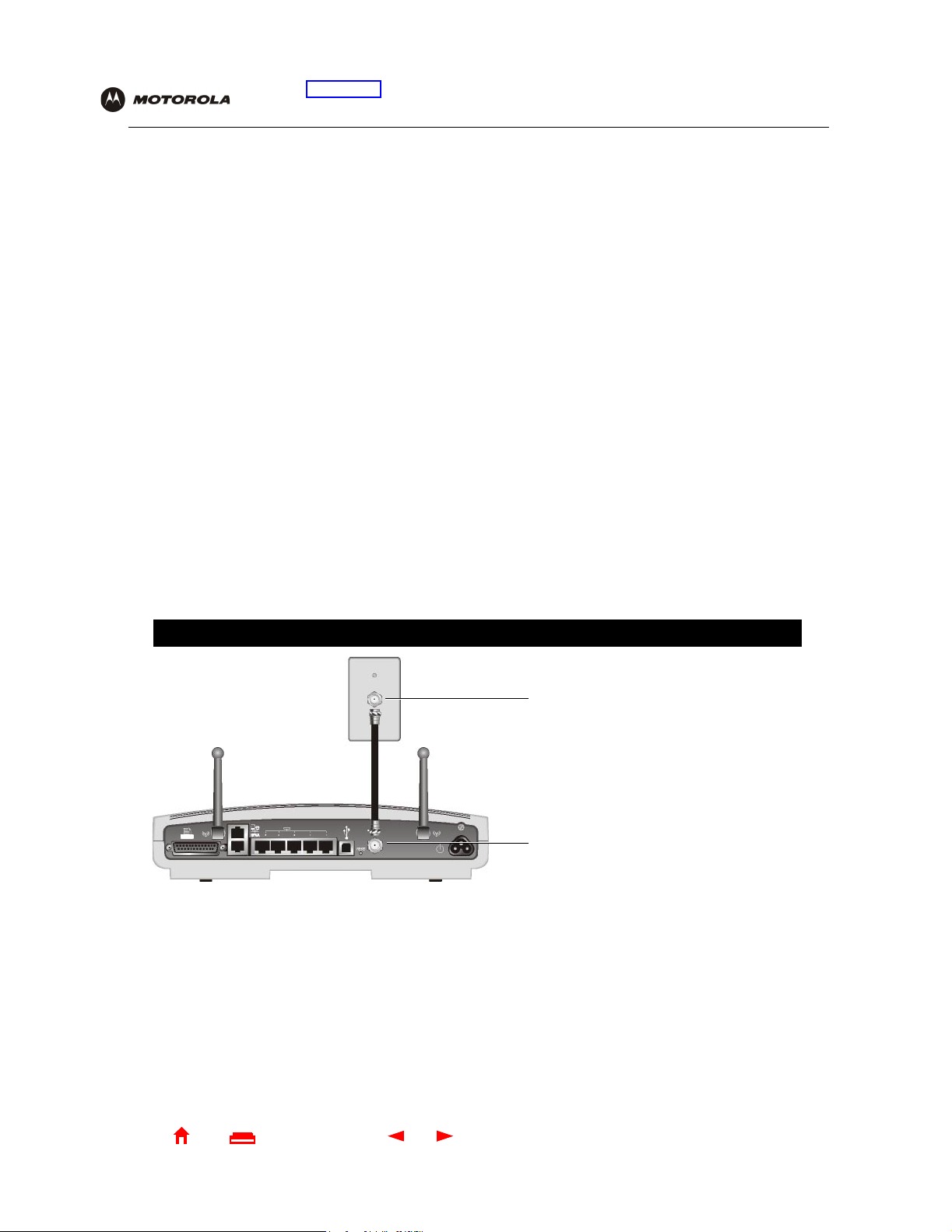
Conne cting th e SBG100 0 t o the Cab l e S ystem
Allow 5 to 30 minutes the first time you turn on the SBG1000 to find and lock on the appropriate communications
channels.
1 Be sure the computer is on and the SBG1000 is unplugged.
2 Connect one end of the coaxial cable to the cable outlet or splitter.
3 Connect the other end of the coax ial cable to the cable connector on the SBG1000.
Hand-tighten the connectors to avoid damaging them.
4 If you are using the optional Motorola External Diversity Antenna, install it now. Follow the instructions in
“Installing the Optional External Diversity Antenna” on page 28.
5 Insert th e Motorola SBG1000 Wireless Cable Modem Gateway CD-ROM into the CD-ROM drive.
6 Plug the power cord into the power connector on the SBG1000.
7 Plug the power cord into the elect ri cal outlet. This turns the Motorola SBG1000 Wireless Cable Modem
Gateway on. You do not need to unplug it when not in use.
8 Check that the light s on the Front Panel cycle through this sequenc e:
• Power icon turns on when AC power i s connect ed t o the SBG1000 and i ndicat es that the power s upply i s
working proper ly
.
• RX (receive) light flashes while scanning for the receive channel and changes to solid green when the
receive channel is locked.
• TX (transmit) ligh t flashes while scanning for the send channel and changes to solid green when the
send channel is locked.
• LNK (link) light flas hes during SBG1000 registration and configur ation and changes to solid green when
the cable modem wireless gateway i s registered.
• Globe icon flashes when the SBG1000 is transmitting or receiving data.
Connecting the SBG1000 to the cable system
1
3
2
4
Home
X
xitPrint
22 SBG1000 Wireless Cable Modem Gateway User Guide
Page 29

E
Overview Installation Troubleshooting Contact FAQ Specifications Glossary License
Configuration: Bas i c Ga te way TCP /IP Wireless Print Server USB
Cabling the Ethernet or HPNA LAN
After connecting to the cable system, you can connect your wired Ethernet and/or HPNA LAN. Some samples are
shown in “Wir ed Ethernet LAN” on page 10 and “HPNA LAN” on page 13. Detailed information about network
cabling is beyond the scope of this document. You must instal l pr oper drivers for the Eth ernet NIC or HPNA
adapter.
Obtaining an IP address in Windows 98, Windows 98 SE, or Windows Me
You must do the following on each Ethernet client PC running Windows 98, Windows 98 SE, or Windows Me:
1 On the Windows Desktop, click Start.
2 Select Run. The Run window is displ ayed.
3 Type winipcfg.exe and click OK. The IP Configuration window is displayed:
4 Click the Renew button to obtain an IP address for the PC from the DHCP server on the SBG1000.
Obtaining an IP address in Windows 2000 or Windows XP
You must do the following on each Ethernet client PC running Windows 2000 or Windows XP:
1 On the Windows Desktop, click Start.
2 Select Run. The Run window is displ ayed.
3 Type cmd and click OK to display a command prompt window.
4 Type ipconfig /renew and press ENTER to obt ain an IP address for the PC from the DHCP server on the
SBG1000.
5 Type exit and press ENTER to return to Windows.
Obtaining an IP address on Macintosh or UNIX Systems
Follow the instructions in your user manual.
Home
X
xitPrint
23 SBG1000 Wireless Cable Modem Gateway User Guide
Page 30

E
Overview Installation Troubleshooting Contact FAQ Specifications Glossary License
Configuration: Bas i c Ga te way TCP /IP Wireless Print Server USB
Connecting a PC to the USB Port
You can connect a single PC running Windows 98, Windows XP, Windows Me, or Windows 2000 to the Motorola
SBG1000 Wireless Cable Modem Gateway USB port.
Caution!
Before plugging in the USB cable, be sure the Motorola SBG1000 Wireless Cable Modem Gateway
CD-ROM is inserted in the PC CD-ROM drive.
To connect a PC to the USB port:
1 Connect the USB cable to the USB port on the SBG1000.
2 Connect the ot her end to the USB port on the computer.
3 Install the USB driver following the appropriate procedure fo r “Set ting Up a USB Driver” on page 95.
Setting Up the Wireless LAN
For information about wireless LAN setup, see “Setting Up the Wireless LAN” on page 67.
Connecting the Prin ter
Connect the printer to the Motor ola SBG1000 Wireless Cable Modem Gateway printer port. If a cable was
supplied with the pri nter, use that cable. Consult your printer documentation to determine cabling requi rements
from the SBG1000 to the printer.
After connecting the printer, power it on and follow the instruct ions for “Configur ing the Print Server” on page 77.
Home
X
xitPrint
24 SBG1000 Wireless Cable Modem Gateway User Guide
Page 31

E
Overview Installation Troubleshooting Contact FAQ Specifications Glossary License
Configuration: Bas i c Ga te way TCP /IP Wireless Print Server USB
Wall Mounting the Wireless Gateway
If you mount the SBG1000 on the wall, you mus t:
• Locate the unit as specified by the local or national codes governing residential or business cable TV and
communications services.
• Follow all local st andards for installing a network int erface unit/network interface device (NIU/NID).
If possible, mount the SBG1000 to concrete, masonry, a wooden stud, or other very solid wall material. Use
anchors if necessa ry; for example if you must mount the unit on drywall.
To mount your SBG1000 on the wall:
1 Print th e Wall Mounting Template on page 27:
Click the Print icon or choose Print from the File menu to display the Print dialog box . ( The following image is
from Adobe Acrobat Reader
Be sure you print the templat e at 100% scale. Be sure Fit to pag e is not checked in the Print dialog box.
Click the OK button to print the template.
®
running on Windows 2000; there may be sl ight differences in your version.)
2 Measure the printed template with a ruler to ensure that it is the correct size.
3 Use a center punch to mark the center of the holes.
4 On the wall, locate the marks for the mounting holes.
Caution!
Before drilling holes, check the structure for potential damage to water, gas, or electric lines.
5 Drill the holes to a depth of at least 3.8 cm (1
6 If necessary, seat an anchor in each hole.
Home
X
xitPrint
1
/2 inches).
25 SBG1000 Wireless Cable Modem Gateway User Guide
Page 32

E
Overview Installation Troubleshooting Contact FAQ Specifications Glossary License
Configuration: Bas i c Ga te way TCP /IP Wireless Print Server USB
Use M5 x 38 mm (#10-16 x 11/2 inch) screws with a fl at underside and maximum screw head diameter of
10.5 mm to mount the SBG1000.
7 Using a screwdr iver, turn each screw until part of it protrudes from the wall, as shown:
• There must be 4.0 mm (.16 inches) between the wall and the unde rsi de of the screw head.
• The maximum distance from the wall to the top of the scre w head is 7. 6mm (.3 in).
7.6 mm (.3 inches) maximum
10.5 mm (.4 inches) maximum
4.0 mm (.16 inches)
8 Place the SBG1000 so the keyholes are above the mounting screws.
9 Slide the SBG1000 down so it stop s against the top of the keyhole opening.
Home
X
xitPrint
26 SBG1000 Wireless Cable Modem Gateway User Guide
Page 33

E
Overview Installation Troubleshooting Contact FAQ Specifications Glossary License
Configuration: Bas i c Ga te way TCP /IP Wireless Print Server USB
Wall Mounting T em plate
You can print this page to use as a wall mounting te mp late.
Be sure you print it at 100% scale. In Acrobat Reader, be sure
that Fit To Page is not checked in the Print dialog box.
Measure the printed template with a ruler to ensure that it is
the correct size.
6.79 in.
17.24 cm.
Home
X
xitPrint
27 SBG1000 Wireless Cable Modem Gateway User Guide
Page 34

E
Overview Installation Troubleshooting Contact FAQ Specifications Glossary License
Configuration: Bas i c Ga te way TCP /IP Wireless Print Server USB
Installing the Optional External Diversity Antenna
The optional Motorola External Diversity Antennas are designed to provide an indoor operating range with WEP
enabled of at least:
Distance Data Tran sfer Rate
30 meters (100 feet) 11 Mbps
50 meters (165 feet) 5.5 Mbps
75 meters (230 feet) 2Mbps
95 meters (300 feet) 1Mbps
The maximum wireless operation distance depends on the type of materials through which the signal must pass
and the location of the diversity antennas and clients (stations). Motorola cann ot guarantee wireless operation for
all supported distances in all environments.
To install the optional Motorola External Diversity Antenna:
1 Be sure the SBG1000 is unplugged. As with all electronic equipment, avoid potential shock by always
unplugging the power cord from the wall outlet or oth er power source before disconnecting it from the
SBG1000 rear panel.
2 Remove the antennas on the SBG1000 by unscrewing the connectors. You may need a pair of needle nose
pliers to loosen them.
Store the antennas supplied on the SBG1000 in a safe place.
Home
X
xitPrint
28 SBG1000 Wireless Cable Modem Gateway User Guide
Page 35

E
Overview Installation Troubleshooting Contact FAQ Specifications Glossary License
Configuration: Bas i c Ga te way TCP /IP Wireless Print Server USB
Disconnecting the antennas provided with the SBG1000
3
Connect the cables from the Motorola External Diversity Antenna to the connectors on the Motorola
SBG1000 Wireless Cable Modem Gateway Front Panel. Hand-tigh ten the connectors to avoid damaging
them. Using exces sive force may damage the connectors.
Home
X
xitPrint
29 SBG1000 Wireless Cable Modem Gateway User Guide
Page 36

E
Overview Installation Troubleshooting Contact FAQ Specifications Glossary License
Configuration: Bas i c Ga te way TCP /IP Wireless Print Server USB
Connecting the Optional External Diversity Antenna to the SBG1000
4
Position or mount the Exte rnal Diversity Antenna in a suitable locat ion away from the computer and mo nitor .
Follow the instruct ions provided with the External Diversity Antenna. Do not twist the antenna cables.
To obtain optimum results, try moving the External Diversity Antennas to slightly different locations.
Home
X
xitPrint
30 SBG1000 Wireless Cable Modem Gateway User Guide
Page 37

E
Overview Installation Troubleshooting Contact FAQ Specifications Glossary License
Configuration: Bas i c Ga te way TCP /IP Wireless Print Server USB
Configuring the SBG1000
Configuring the SBG1000 inc ludes:
• Starting the SBG1000 Setup Program (see page 32)
• Changing the Default Passwor d (see page 34)
• Getting Help (see page 35)
• Setting the Firewall Policy (see page 36)
For more informat ion about confi gurati on, see “Confi guring TCP/I P” on p age 53, “Setting Up the Wireless LAN” on
page 67, “Configuring the Print Server” on page 77, or “Setting Up a USB Driver” on page 95.
For normal operation, you do not need to change most default settings. The following caution statements
summarize the issues you must be aware of:
Caution!
To prevent unauthorized configuration, change the default passwor d immediately when you first
configure the Motorola SBG1000 Wireless Cable Modem Gateway. See “Changing the Default
Password” on page 34
Firewalls are not foolproof. Ch oose the most sec ure fi rewall pol icy you can. See “Sett ing th e Firewall
Policy” on page 36.
For a wireless LAN only, be sure you follow the instructi ons in “Setting Up the Wireless LAN” on
page 67.
Home
X
xitPrint
31 SBG1000 Wireless Cable Modem Gateway User Guide
Page 38

E
Overview Installation Troubleshooting Contact FAQ Specifications Glossary License
Configuration: Bas i c Ga te way TCP /IP Wireless Print Server USB
Starting the SBG1000 Setup Program
1 On a c omput er on th e LAN, open a web browser.
2 In the Address or Location field, type 192.168.100.1 and press ENTER to display the Login window:
3 Click Login to display the Enter Network Password window :
4 In the User Name field, type the User Name (the default is “admin”).
5 In the Passwor d field, type the Password (the default is “motorola”).
Home
X
xitPrint
32 SBG1000 Wireless Cable Modem Gateway User Guide
Page 39

E
Overview Installation Troubleshooting Contact FAQ Specifications Glossary License
Configuration: Bas i c Ga te way TCP /IP Wireless Print Server USB
6 Click OK to display the SBG1000 Setup Progr am :
Click To Perform
Cable C onfigure and monitor the cable system connection
Gateway Configure and monitor the gateway preferences (see “Configuring the Gateway” on page43)
Wireless Configure and monitor the wireless interface (see “Setting Up the Wireless LAN” on page 67)
Firewall Configure and monitor the firewall (see “Settin g the Firewall Policy” on page 36)
Printer C onfigure the SBG1000 print server (see “Configuring the Print Server” on page 77)
Admin Changing the Default Password (see page 34)
Help Display information about the SBG1000 (see “Getting Help” on page 35)
Info Display information about the
Reboot Restart the SBG1000. It is the same as pressing the reset button on the Rear Pan el for less than five
seconds.
For some settings, after you edi t the field and click Apply, you are warned that you must Reboot for your
change to take effect. Rebooting takes 10 to 15 second s. Af ter rebooting, you must log-in again.
SBG1000 Setup Program
Home
X
xitPrint
33 SBG1000 Wireless Cable Modem Gateway User Guide
Page 40

E
Overview Installation Troubleshooting Contact FAQ Specifications Glossary License
Configuration: Bas i c Ga te way TCP /IP Wireless Print Server USB
Changing the Default Password
Caution!
To prevent unauthorized co nfi guration, change the default password immediately when you firs t
configure the Motorola SBG1000 Wireless Cable Modem Gateway.
To change the default password :
1 On the SBG1000 Setup Program screen, click Admin to display the ADMIN — basic page:
2 Type the old password in the Old Password field. (The default password is “motorola.”)
3 Type the new password in the New P asswor d field.
4 Type the new password again in the V erify Password field.
5 Click Apply to apply your changes.
Home
X
xitPrint
34 SBG1000 Wireless Cable Modem Gateway User Guide
Page 41

E
Overview Installation Troubleshooting Contact FAQ Specifications Glossary License
Configuration: Bas i c Ga te way TCP /IP Wireless Print Server USB
Getting Help
To get help on any underlined item, field, click the text. For example, if you click a fi eld or the help button on the
ADMIN — basic page, the followi ng help is displayed:
This button also displ ays
help for the window.
You can scroll to browse the help, or click anot her item to display hel p for that item.
Home
X
xitPrint
35 SBG1000 Wireless Cable Modem Gateway User Guide
Page 42

E
Overview Installation Troubleshooting Contact FAQ Specifications Glossary License
Configuration: Bas i c Ga te way TCP /IP Wireless Print Server USB
Setting the Firewall Policy
Caution!
Firewalls are not foolproof. Choose the most secure firewall policy you can. To enable easy network
setup, the default fi rewall policy is Low, which provides minimum security.
To select a predefined policy for all packets processed by the firewall:
1 On the SBG1000 Setup Program left panel, click Firewall.
2 Click POLICY.
3 Click basic to display the options for firewall policy:
4 Select one of the followi n g. Unless you have the necessary expertise and need to setup a custom firewal l,
use High, Medium, or Low:
High Safest confi gu rat i on, highest security . We rec o mmend this setting.
Medium Common configuration, modest risk
Low Minimum security, higher risk
Custom You can create a custom firewall policy on the Firewall > POLICY — advanced Page (see page 39). Do
not create a custom policy unless you have the necessary expertise and the need to do so.
None This setting disables the firewall and provides no security. We do not reco mme nd this setting.
5 Click Apply to apply your changes.
Home
X
xitPrint
36 SBG1000 Wireless Cable Modem Gateway User Guide
Page 43

E
Overview Installation Troubleshooting Contact FAQ Specifications Glossary License
Configuration: Bas i c Ga te way TCP /IP Wireless Print Server USB
Firewall Pages in the SBG1000 Setup Program
Use the foll owing pages to configure the firewall:
• Firewall > POLICY — basic Page (see page 38)
• Firewall > POLICY — advanced Page (see page 39)
• Firewall > ALERT — basic Page (see page 40)
• Firewall > ALERT — email Page (see page 41)
• Firewall > LOGS Page (see page 42)
For some settings, after you edi t the field and click Apply, you are warned that you must Reboot for your
change to take effect. Rebooting takes 10 to 15 second s. Af ter rebooting, you must log-in again.
Home
X
xitPrint
37 SBG1000 Wireless Cable Modem Gateway User Guide
Page 44

E
Overview Installation Troubleshooting Contact FAQ Specifications Glossary License
Configuration: Bas i c Ga te way TCP /IP Wireless Print Server USB
Firewall > POLICY — basic Page
Use this page to select a pre defined firewall policy for all packets processed by the SBG1000 firewall, as
described in “Setti ng the Firewall Policy” on page36. Advanced users only can create a custom policy on the
Firewall > POLICY — advanced Page (see page 39). The FIREWALL POLICY setting None disables the fire wall
and provides no securi ty. We do not recommend thi s setting.
The predefined polici es provide outboun d Internet access for computers on the SBG1000 LAN.
The SBG1000 firewall uses stat eful inspection to allow inbound responses when there already is an outbound
session running corresponding to t he data flow. For example, if you use a web browser, outbound HTTP
connections are permitted on port 80. Inbound responses from the Internet are allowed because an outbound
session is esta blished. When required, the SBG1000
without first establishing an outbound session.
firewall can be configured to allow inbound packets
Home
X
xitPrint
38 SBG1000 Wireless Cable Modem Gateway User Guide
Page 45

E
Overview Installation Troubleshooting Contact FAQ Specifications Glossary License
Configuration: Bas i c Ga te way TCP /IP Wireless Print Server USB
Firewall > POLICY — advanced Page
Use this page to construct a custom firewall policy.
Firewall > POLICY — advanced page fields
Field Description
Port ID The name of the protocol being filtered.
Enable Check this box to enable firewall policy filtering for the port.
Port Range
(From:To)
Allowed Protocol The allowed protocols.
Allow IB (Inbound) Filters inbound data from the Internet on the specified ports.
Allow OB (Outbound) Filters outbound data to the Internet on the specified ports. Stateful insp ection ensures
Protocol # The protocol number associated with the IP packets to allow in the firewall policy.
Sets the from and to port range, which must contain all ports required by the protocol.
appropriate responses for outbound sessions.
Home
X
xitPrint
39 SBG1000 Wireless Cable Modem Gateway User Guide
Page 46

E
Overview Installation Troubleshooting Contact FAQ Specifications Glossary License
Configuration: Bas i c Ga te way TCP /IP Wireless Print Server USB
Firewall > ALERT — basic Page
Use this page to set the alert mechanism for firewall intrusi on detection events.
Firewall > ALERT — basic page fields
Field or Button Description
Intrusion Detection Check Email to be alerted through SMTP e-mail. An SMTP server that does not require any
authentication such as a user name or password must be present to receive the e-mail.
Apply Click to apply your changes.
Home
X
xitPrint
40 SBG1000 Wireless Cable Modem Gateway User Guide
Page 47

E
Overview Installation Troubleshooting Contact FAQ Specifications Glossary License
Configuration: Bas i c Ga te way TCP /IP Wireless Print Server USB
Firewall > ALERT — email Page
Use this page to configure the e-mail alert parameters:
Firew all > ALERT — emai l page fields
Field or Button Description
E-mail Server IP Address Sets the e-mail server IP address, in dotted-decimal format.
E-mail Ser ver Port Sets the e-mail s erver port number.
E-mail Sender Sets the sender e-mail address.
E-mail Recipient List Sets the list of e-mail addresses that receive alerts from the
Apply Click to apply your changes.
SBG1000 firewall.
Home
X
xitPrint
41 SBG1000 Wireless Cable Modem Gateway User Guide
Page 48

E
Overview Installation Troubleshooting Contact FAQ Specifications Glossary License
Configuration: Bas i c Ga te way TCP /IP Wireless Print Server USB
Firewall > LOGS Page
Use this page to set which firewall events are logged.
Firewall > LO GS page fie ld s
Field or Button Description
Enable Session Log Check this box to log session events.
Enable Blocking Log Check this box to log blocking events.
Enable Intrusion Log Check this box to log intrusions.
Apply Click to apply your changes.
Home
X
xitPrint
42 SBG1000 Wireless Cable Modem Gateway User Guide
Page 49

E
Overview Installation Troubleshooting Contact FAQ Specifications Glossary License
Configuration: Bas i c Ga te way TCP /IP Wireless Print Server USB
Configuring the Gateway
This section describes the Gateway configuration pages in t he SBG1000 Setup Program:
• Gateway > STATUS Page (see page 44)
• Gateway > WAN Page (see page 45)
• Gateway > LAN — nat config Page (see page 47)
• Gateway > LAN — dhcp server config Page (see page 48)
• Gateway > LAN — dhcp reservations Page (see page 49)
• Gateway > LOG Page (see page 51)
For some settings, after you edi t the field and click Apply, you are warned that you must Reboot for your
change to take effect. Rebooting takes 10 to 15 second s. Af ter rebooting, you must log-in again.
Home
X
xitPrint
43 SBG1000 Wireless Cable Modem Gateway User Guide
Page 50

E
Overview Installation Troubleshooting Contact FAQ Specifications Glossary License
Configuration: Bas i c Ga te way TCP /IP Wireless Print Server USB
Gateway > STATUS Page
This page displays the gateway status information:
These fields display settings that are set on the other Gateway pages. For descriptions, see the sections about
those pages.
Home
X
xitPrint
44 SBG1000 Wireless Cable Modem Gateway User Guide
Page 51

E
Overview Installation Troubleshooting Contact FAQ Specifications Glossary License
Configuration: Bas i c Ga te way TCP /IP Wireless Print Server USB
Gateway > WAN Page
Use this page to configure the external (public) wide area network (WAN) interface:
Gateway > WAN pag e fields
Field Description
Host Name If th e c able service prov ide r requires a hostname to acces s to thei r netw ork, ty pe the hostname
they provided in this field. The default is None.
Enable DHCP Client Enabling the DHCP client causes the wireless gateway to automatically obtain the public IP
address, subnet mask, domain name, and DNS server(s). Most commonly, the DHCP client is
enabled if the cable service provider automatically assigns a public IP address from their
DHCP server. Enable DHCP Client is on by default.
Disable DHCP Client If the cable service provider does not automatically assign a public IP address using DHCP,
they must provide a static IP address. Select Disable DHCP Client. When you disable the
DHCP client, you must type the static IP address, subnet mask, DNS server(s), and domain
name (if necessary) in the fields provided. Disable DHCP Client is off by default.
Static IP Address I f Disable DHCP C l ient is on, type t he static IP address provi ded by t he cab l e ser vi ce provider,
in dotted-decimal format. The default is None.
Static IP Address
Subnet Mask
Domain Name If the cable service pro vider requires a doma i n nam e, type the domain n ame t he y p r ov i ded yo u
Home
If Disable DHCP Client is on, type the subnet mask associated with the static IP address, in
dotted-decimal format. The de fa ult is None.
in this field. The default is N one.
X
xitPrint
45 SBG1000 Wireless Cable Modem Gateway User Guide
Page 52

E
Overview Installation Troubleshooting Contact FAQ Specifications Glossary License
Configuration: Bas i c Ga te way TCP /IP Wireless Print Server USB
Gateway > WAN pag e fields (continued)
Field Description
DNS IP Address 1
DNS IP Address 2
DNS IP Address 3
TCP Session Wait
Timeout
UDP Session Wait
Timeout
ICMP Session Wait
Timeout
Apply Click to apply your changes.
The cable service provider DNS server provides name-to-IP address resolution. If the cable
service provider does not automatically assign DNS addresses from their DHCP server, they
must provide at least one DNS server IP address to enter in these fields, in dotted-decimal
format. The default is None.
Sets the maximum time in minutes to wait before assuming a TCP session has timed out. The
default is 5 minutes.
Sets the ma ximu m ti m e in minu t es to wa it befo r e ass umi ng a UDP session has timed out. The
default is 5 minutes.
Sets the maximum time in minutes to wait before assuming an ICMP session has timed out.
The default is 5 minutes.
Home
X
xitPrint
46 SBG1000 Wireless Cable Modem Gateway User Guide
Page 53

E
Overview Installation Troubleshooting Contact FAQ Specifications Glossary License
Configuration: Bas i c Ga te way TCP /IP Wireless Print Server USB
Gateway > LAN — nat config Page
Use this page to configure NAT:
Gatew ay > LAN — nat confi g page fiel ds
Field or Button Description
LAN
Enable NAT If enabled, the single HFC IP Address (public IP address) assigned by the cable service
provider is mapped to many private IP addresses on the
Apply Click to apply your changes. You must reboot the SBG1000.
NEW NAT
PASSTHROUGH
MAC Address Sets the MAC address of the passthrough client. The format is 16 hexadecimal numerals.
DMZ Check the box to set the MAC address as a de-militarized zone (DMZ) client. A DMZ is a
Add Click to add the IP address to the reserved IP address table.
CURRENT NAT
PASSTHROUGH
Delete Click to delete the MAC address from the NAT passthrough list.
NAT Passthrough is used to identify which CPEs are passthrough devices, not subject to
network address translation. Up to 32 NAT passthrough CPEs can be entered using the
CPE MAC address. When configuring a CPE as a NAT passthrough device, you may also
identify whether the CPE should be treated as a de-militarized zone (DMZ) host. A DMZ host
is a CPE device that is completely exposed to the Internet. Any CPE device configured as a
DMZ is open to Internet hackers and should be used w ith extreme caution.
computer on the LAN that can be accessed from the public Internet.
Displays the NAT passthrough list.
SBG1000 LAN.
Home
X
xitPrint
47 SBG1000 Wireless Cable Modem Gateway User Guide
Page 54

E
Overview Installation Troubleshooting Contact FAQ Specifications Glossary License
Configuration: Bas i c Ga te way TCP /IP Wireless Print Server USB
Gateway > LAN — dhcp server config Page
Experienced network administrators only can use this page to perform advanced DHCP server confi guration:
CAUTION!
Do not modify these setti ngs unless you are an experienced network admini str ator with strong
knowledge of IP addressing, subnetting, and DHCP.
Gateway > LAN — advanced page fields
Field Description
LAN IP Address Sets the SBG1000 LAN IP address, in dotted-decim al format. The default is 192.168.0.1.
LAN IP Subnet Mask Sets the subnet mask, in dotted-decimal format. The default is 255.255.255.0
Starting IP Address Sets the starting IP address assigned by the
dotted-decimal format. The default is 192.1 68. 0 . 2.
# of DHCP Users Sets the number of clients for the
There are 253 possible client addresses. The default is 253.
DHCP Server Lease
Time
Domain Name Sets the domain name for the SBG1000 LAN. The default is None.
Time To Live Sets the TTL (hop limit) for outbound packets. The default is 64.
Interface Maximum
Transmission Unit
Sets the tim e in seconds that the
default is 60 seconds.
Sets the SBG1000 LAN MTU, in bytes. The minimum is 68 bytes. The default is 1500 bytes.
SBG1000 DHCP server to assign a private IP address.
SBG1000 DHCP server leases an IP address t o a c l ient. The
SBG1000 DHCP server to clients, in
Apply Click to apply your changes. You must reboot the
Home
X
xitPrint
48 SBG1000 Wireless Cable Modem Gateway User Guide
SBG1000.
Page 55

E
Overview Installation Troubleshooting Contact FAQ Specifications Glossary License
Configuration: Bas i c Ga te way TCP /IP Wireless Print Server USB
Gateway > LAN — dhcp reservations Page
Use this page to configure DHCP reservations:
Gateway > LAN — dhcp reservations page fields
Field Description
RESERVE NEW IP
ADDRESS
MAC Address Type the MAC address of the DHCP client for which a reserved IP address is required. The
IP Address Sets the host portion of the reserved IP address for the LAN client having the specified MAC
DMZ Check this box if you want the host to bypass NAT and be exposed directly to the Internet.
Host Name If your ISP requires a hostname to access their network, enter the hostname provided to you
Add Click Add to reserve a new IP address.
You can reserve up to 32 IP addresses assigned by the SBG1000 DHCP server for specific
LAN clients. For example, you can reserve an IP address for a private FTP server to ensure
that it always receives the same private IP address.
form at is 16 hexadecimal numerals.
address. When the LAN client requests an IP address, the SBG1000 D HCP server assigns
the client this IP address.
When conf igu r ing a client as a NAT passthro ugh device, you can spe ci fy whe t he r i t should be
a de-militarized zone (DMZ) host. A DMZ host is completely exposed to th e Internet. Any
device configured as a DMZ is open to Internet hackers and should be used with extreme
caution.
in the Host Name field.
Home
X
xitPrint
49 SBG1000 Wireless Cable Modem Gateway User Guide
Page 56

E
Overview Installation Troubleshooting Contact FAQ Specifications Glossary License
Configuration: Bas i c Ga te way TCP /IP Wireless Print Server USB
Gateway > LAN — dhcp reservations page fields (continued)
Field Description
CURRENTLY
RESERVED IP
ADDRESSES
MAC Address Displays the reserved MAC addresses.
IP Address Displays the reserved IP addresses.
DMZ Displays whether the client is configured as a DMZ.
Host Name Displa ys the host name.
Delete Click this box to remove the reserved IP address for the client.
Delete C lick this button to remove the reserved IP addresses for clients designated by the Delete
Displays all DHCP clients that have specific IP addresses reserved for their use by MAC and
IP address.
box.
Gateway > ALG — basic Page
This may not be supported i n your code release. For the most recent documentation, visit the Product
Documentation page on www.motorola.com/broadband.
Gateway > ALG — advanced Page
This may not be supported i n your code release. For the most recent documentation, visit the Product
Documentation page on www.motorola.com/broadband.
Home
X
xitPrint
50 SBG1000 Wireless Cable Modem Gateway User Guide
Page 57

E
Overview Installation Troubleshooting Contact FAQ Specifications Glossary License
Gateway > LOG Page
Use this page to:
Configuration: Bas i c Ga te way TCP /IP Wireless Print Server USB
Gateway > LOG page fields
Field Description
Time The data and time in the format yyyy-mm-dd hh:mm:ss (hours hh are 00 to 23)
Priority Indicates the importance of the message.
Code
Message Describes the event.
Home
X
xitPrint
51 SBG1000 Wireless Cable Modem Gateway User Guide
Page 58

E
Home
X
xitPrint
52 SBG1000 Wireless Cable Modem Gateway User Guide
Page 59

E
Overview Installation Troubleshooting Contact FAQ Specifications Glossary License
Configuration: Bas i c Ga te way TCP /IP Wireless Print Server USB
Configuring TCP/IP
You must be sure all client computers are conf igured for TCP/IP (a protocol for communicati on between
computers). Perform one of:
• “Configuring TCP/IP in Windows 95, Windows 98, or Windows Me” on page 54
• “Configuring TCP/IP in Windows 2000” on page 56
• “Configuring TCP/IP in Windows XP” on page 60
• Follow the i nstructions in your Macintosh or UNIX user manual
After configuring TCP/IP, perform one of the following to verify the IP address:
• “Ve ri fying the IP Address in Windo ws 95, Windows 98, or Windows Me” on page 64
• “Ve ri fying the IP Address in Windo ws 2000 or Windows XP” on page 65
• Follow the i nstructions in your Macintosh or UNIX user manual
Home
X
xitPrint
53 SBG1000 Wireless Cable Modem Gateway User Guide
Page 60

E
Overview Installation Troubleshooting Contact FAQ Specifications Glossary License
Configuration: Bas i c Ga te way TCP /IP Wireless Print Server USB
Configuring TCP/IP in Windows 95, Windows 98, or Windows Me
1 On the Windows Desktop, click Start.
2 Select Settings and then Control Panel from the pop-up menus to display t he Control Panel window.
3 Double-click the Network icon to display the Network window:
Although your SBG model number may be different than in the images in this guide,
the procedure is the same.
4 Select the Configuration tab.
5 Verif y that TCP/IP is installed for the adapter used to connect to the SBG1000. If TCP/IP is inst alled, skip to
step 10. If TCP/IP is not inst alled for the adapter, continue with step 6.
6 Select the adapter to use f or th e SBG10 00 connection and click Add. The Select Network Component Type
window is displayed:
7 Click Protocol and click the Add button.
Home
X
xitPrint
54 SBG1000 Wireless Cable Modem Gateway User Guide
Page 61
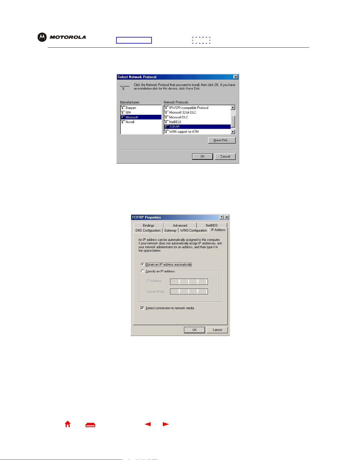
E
Overview Installation Troubleshooting Contact FAQ Specifications Glossary License
Configuration: Bas i c Ga te way TCP /IP Wireless Print Server USB
8 Click Microsoft in the Manufacturers section and click TCP/IP in the Network Protocol section of Select
Network Protocol window:
9 Click OK.
10 Click TCP/IP on the Network window. If ther e is more than one TCP/IP entry, choose the one for the Ethernet
card or USB port connected to the SBG1000.
11 Click Properties. The TCP/IP Properties window is displayed:
12 Click the IP Address tab.
13 Click Obtain an IP address automatically.
14 Click OK to accept the TCP/IP settings.
15 Click OK to close the Network window.
16 Click OK when prompted to restart the computer and click OK again.
When you complete TCP/IP confi guration, go to “Verifying the IP Address in Windows95, Windows 98, or
Windows Me” on page 64.
Home
X
xitPrint
55 SBG1000 Wireless Cable Modem Gateway User Guide
Page 62

E
Overview Installation Troubleshooting Contact FAQ Specifications Glossary License
Configuration: Bas i c Ga te way TCP /IP Wireless Print Server USB
Configuring TCP/IP in Windows 2000
1 On the Windows Desktop, click Start.
2 Select Settings and then Control Panel from the pop-up menus to display t he Contr ol Panel window:
3 Double-click the Network and Dial-up Connections icon to display the Network and Dial-up Connections
window:
Home
X
xitPrint
56 SBG1000 Wireless Cable Modem Gateway User Guide
Page 63

E
Overview Installation Troubleshooting Contact FAQ Specifications Glossary License
Configuration: Bas i c Ga te way TCP /IP Wireless Print Server USB
4 Click Local Area Connection number. The value of number varies from system to system. The Local Area
Connection number Status window is displayed:
5 Click Properties. Information similar to the following window is displayed:
6 If Internet Protocol (TCP/IP) is in the list of components, TCP/IP is installed. You can skip to step 10.
If Internet Protocol (TCP/IP) is not in the list, cli ck Install. The Sel ect Network Component Type window is
displayed:
Home
X
xitPrint
57 SBG1000 Wireless Cable Modem Gateway User Guide
Page 64

E
Overview Installation Troubleshooting Contact FAQ Specifications Glossary License
Configuration: Bas i c Ga te way TCP /IP Wireless Print Server USB
7 Click Protocol on the Select Network Component Type window and click Add. The Select Network Protocol
window is displayed:
8 Click Internet Protocol (TCP/IP).
9 Click OK. The Local Area Connection number Properties window is re-displayed.
10 Be sure the box next to Internet Protocol ( TCP/I P) is checked.
Home
X
xitPrint
58 SBG1000 Wireless Cable Modem Gateway User Guide
Page 65

E
Overview Installation Troubleshooting Contact FAQ Specifications Glossary License
Configuration: Bas i c Ga te way TCP /IP Wireless Print Server USB
11 Click Properties. The Internet Protocol (TCP/I P) Pr operties window is displayed:
12 Be sure Obtain IP add ress aut o m a ti ca l ly and Obtain DNS server address automaticall y are selected.
13 Click OK to accept the TCP/IP settings.
14 Click OK to close the Local Area Connection number Properties window.
15 Click OK when prompted to restart the computer and click OK again.
When you complete the TCP/IP conf iguration, go to “Verifying the IP Address in W indows 2000 or WindowsXP”
on page 65.
Home
X
xitPrint
59 SBG1000 Wireless Cable Modem Gateway User Guide
Page 66

E
Overview Installation Troubleshooting Contact FAQ Specifications Glossary License
Configuration: Bas i c Ga te way TCP /IP Wireless Print Server USB
Configuring TCP/IP in Windows XP
1 On the Windows desktop, click Start to display the Start window:
2 Click Control Panel to disp lay the Control Panel window. The display varies, depending on the Windows XP
view options. If the displ ay is a Category view as show n below, continue with step 3. Otherwi se, skip to
step 5.
Home
X
xitPrint
60 SBG1000 Wireless Cable Modem Gateway User Guide
Page 67

E
Overview Installation Troubleshooting Contact FAQ Specifications Glossary License
Configuration: Bas i c Ga te way TCP /IP Wireless Print Server USB
3 Click Network and Internet Connections to display the Network and Internet Connecti ons window:
4 On the Network and Internet Connections window in the “or pi ck a Control Panel icon, click Network
Connections to display the LAN or High-speed Inter net connections. Skip to step 6.
5 If a classic view simi lar to below is displayed, click Network Connecti ons to display the LAN or High-speed
Internet connections:
Home
X
xitPrint
61 SBG1000 Wireless Cable Modem Gateway User Guide
Page 68

E
Overview Installation Troubleshooting Contact FAQ Specifications Glossary License
Configuration: Bas i c Ga te way TCP /IP Wireless Print Server USB
6 Right-click on t he network connection. If more t han one connection is displayed, be sure to select the one for
your network interface:
7 Select Properties from the pop-up menu to display the Local Area Connection Prope rties window:
8 On the Local Area Connection Prop erties window, be sure Internet Prot ocol (TCP/IP) is checked . If it is not
checked, check it.
Home
X
xitPrint
62 SBG1000 Wireless Cable Modem Gateway User Guide
Page 69

E
Overview Installation Troubleshooting Contact FAQ Specifications Glossary License
Configuration: Bas i c Ga te way TCP /IP Wireless Print Server USB
9 Select Internet Protocol (TCP/IP) and click Properties to display the Internet Protocol (TCP/IP) Properties
window:
10 On the Internet Protocol (TCP/I P) Properties window, verify that the settings are cor rect, as shown above.
11 Click OK to close the TCP/IP Properties window.
12 Click OK to close the Local Area Connection Properties window.
When you complete the TCP/IP conf iguration, go to “Verifying the IP Address in Windows 2000 or Windows XP”
on page 65.
Home
X
xitPrint
63 SBG1000 Wireless Cable Modem Gateway User Guide
Page 70

E
Overview Installation Troubleshooting Contact FAQ Specifications Glossary License
Configuration: Bas i c Ga te way TCP /IP Wireless Print Server USB
Verifying the IP Address in Windows 95, Windows 98, or Windows Me
To check the IP address:
1 On the Windows Desktop, click Start.
2 Select Run. The Run window is displ ayed.
3 Type winipcfg.exe and click OK. The IP Configuration window is displayed. The Ethernet Adpater
Information field will vary depending on the system, as shown in the foll owing examples:
The values for Adapter Address, IP Address, Subnet Mask, and Default Gateway on the PC will be different
than in the image.
In Windows 98, if “Autoconfiguration” is displayed before the IP Address as in the following image, call your
service provider.
4 Select the adapter name — the Ethern et card or USB device.
5 Click Renew.
6 Click OK after the system displays an IP address.
If after perfor m ing this procedure the computer cannot acc ess the Internet, cal l your cable service provider for
help.
Home
X
xitPrint
64 SBG1000 Wireless Cable Modem Gateway User Guide
Page 71

E
Overview Installation Troubleshooting Contact FAQ Specifications Glossary License
Configuration: Bas i c Ga te way TCP /IP Wireless Print Server USB
Verifying the IP Address in Windows 2 000 or Windows XP
To check the IP address:
1 On the Windows Desktop, click Start.
2 Select Run. The Run window is displ ayed.
3 Type cmd and click OK to display a command prompt window.
4 Type ipconfig and press ENTER to display the IP configuration. A display similar to the following indicates a
normal configur ati on:
If an Autoconfigurat ion IP Address is displ ayed as in the following window, there is an incorrect connect ion
between the PC and the SBG1000 or there are cabl e network problems. Check the cable connections and
determine if you can view cable-TV channels on your television:
After verifyi ng the cable connections and proper cable-TV operation, renew the IP address.
Home
X
xitPrint
65 SBG1000 Wireless Cable Modem Gateway User Guide
Page 72

E
Overview Installation Troubleshooting Contact FAQ Specifications Glossary License
Configuration: Bas i c Ga te way TCP /IP Wireless Print Server USB
To renew the IP address:
1 Type ipconfig /renew and press ENTER. If a valid IP address is display ed as shown, Internet access should
be available.
2 Type exit and press ENTER to return to Windows.
If after perfor m ing this procedure the computer cannot acc ess the Internet, cal l your cable service provider
for help.
Home
X
xitPrint
66 SBG1000 Wireless Cable Modem Gateway User Guide
 Loading...