

Page 1
Administrator’s Handbook
ARRIS® Embedded Software Version 9.1.0
ARRIS® NVG599 VDSL2 Gateway
Page 2

Administrator’s Handbook
Copyright
©ARRIS Enterprises, Inc. 2013 Al l rights reserve d. No part of this publication may be reproduced in any form or by any means or
used to make any derivative work (such as translation, transformation, or adaptation) without written permission from ARRIS
Enterprises, Inc. (“ARRIS”). ARRIS reserves the right to revise this publication and to make changes in content from time to time
without obligation on the part of ARRIS to prov ide notification of such revision or change.
ARRIS and the ARRIS logo are all trademarks of ARRIS Enterprises, Inc. Other trademarks and trade names may be used in this
document to r efer to either the entities claiming the marks and the names of their products. ARRIS d isclaims propr ietary interest in
the marks and names of others. MOTOROLA and the Stylized M logo are trademarks or registered trademarks of Motorola
Trademark Holdings, LLC. and are used by ARRIS under licens e. All other product or service names are the property of their
respective owners.
ARRIS provides t hi s g ui de wit ho ut warr a nt y o f any ki nd, i mpl i ed or ex pr es se d, in cl ud in g, bu t n ot l im it ed t o, th e i mp li ed war ran tie s of
merchantability and fitness for a particular purpose. ARRIS may make impr ovements or changes in the product(s) described in this
manual at any time.
The capabilities, system requirements and/or compatibility with third-party products described herein are subject to change without
notice.
EXCEPT AS INDICATED IN THE APPLICABLE SYSTEM PURCHASE AGREEMENT, THE SYSTEM, DOCUMENTATION AND
SERVICES ARE PROVIDED "AS IS", AS AVAILABLE, WITHOUT WARRANTY OF ANY KIND. ARRIS GROUP, INC. (“ARRIS”)
DOES NOT WARRANT THAT THE SYSTEM WILL MEET CUSTOMER'S REQUIREMENTS, OR THAT THEIR OPERATION WILL
BE UNINTERRUPTED OR ERROR-FREE, OR THAT ANY ERRORS CAN OR WILL BE FIXED. ARRIS HEREBY DISCLAIMS ALL
OTHER WARRANTIES, EXPRESS OR IMPLIED, ORAL OR WRITTEN, WITH RESPECT TO THE SYSTEM AND SERVICES
INCLUDING, WITHOUT LIMITATION, ALL IMPLIED WARRANTIES OF TITLE, NON-INFRINGEMENT, INTEGRATION,
MERCHANTABILITY OR FITNESS FOR ANY PARTICULAR PURPOSE AND ALL WARRANTIES ARISING FROM ANY COURSE
OF DEALING OR PERFORMANCE OR USAGE OF TRADE.
EXCEPT AS INDICATED IN THE APPLICABLE SYSTEM PURCHASE AGREEMENT, ARRIS SHALL NOT BE LIABLE
CONCERNING THE SYSTEM OR SUBJECT MATTER OF THIS DOCUMENTA TION, REGARDLESS OF THE FORM OF ANY
CLAIM OR ACTION (WHETHER IN CONTRACT, NEGLIGENCE, STRICT LIABILITY OR OTHERWISE), FOR ANY (A) MATTER
BEYOND ITS REASONABLE CONTROL, (B) LOSS OR INACCURACY OF DATA, LOSS OR INTERRUPTION OF USE, OR
COST OF PROCURING SUBSTITUTE TECHNOLOGY, GOODS OR SERVICES, (C) INDIRECT, PUNITIVE, INCIDENTAL,
RELIANCE, SPECIAL, EXEMPLARY OR CONSEQUENTIAL DAMAGES INCLUDING, BUT NOT LIMITED TO, LOSS OF
BUSINESS, REVENUES, PROFITS OR GOODWILL, OR (D) DIRECT DAMAGES, IN THE AGGREGATE, IN EXCESS OF THE
FEES PAID TO IT HEREUNDER FOR THE SYSTEM OR SERVICE GIVING RISE TO SUCH DAMAGES DURING THE 12MONTH PERIOD PRIOR TO THE DATE THE CAUSE OF ACTION AROSE, EVEN IF COMPANY HAS BEEN ADVISED OF THE
POSSIBILITY OF SUCH DAMAGES. THESE LIMITATIONS ARE INDEPENDENT FROM ALL OTHER PROVISIONS OF THIS
AGREEMENT AND SHALL APPLY NOTWITHSTANDING THE FAILURE OF ANY REMEDY PROVIDED HEREIN.
All ARRIS products are furnished under a license agreement included with the product. If you are unable to locate a copy of the
license agreement, please contact ARRIS.
Part Number
591861-001-00
V9.1.0
TABLE 1.
Document Change Log
Draft version Firmware version Changes this draft
1 tbd First release
Page 3

Table of Contents
Table of Contents
CHAPTER 1 - Introduction . . . . . . . . . . . . . . . . . . . . . . . . . . . . . . . . . . . . . 7
About ARRIS Documentation
Related Documentation
Documentation Conventions
General. . . . . . . . . . . . . . . . . . . . . . . . . . . . . . . . . . . . . . . . . . . . . . . . . . . . . . . . . . . 8
Internal Web Interface . . . . . . . . . . . . . . . . . . . . . . . . . . . . . . . . . . . . . . . . . . . . . . 8
Command Line Interface. . . . . . . . . . . . . . . . . . . . . . . . . . . . . . . . . . . . . . . . . . . . . 8
Organization
. . . . . . . . . . . . . . . . . . . . . . . . . . . . . . . . . . . . . . . . . . . . . 9
A Word About Example Screens
. . . . . . . . . . . . . . . . . . . . . . . . . . . . . . . . 7
. . . . . . . . . . . . . . . . . . . . . . . . . . . . . . . . . . . . 7
. . . . . . . . . . . . . . . . . . . . . . . . . . . . . . . . . 8
. . . . . . . . . . . . . . . . . . . . . . . . . . . . . . 9
CHAPTER 2 - Device Configuration . . . . . . . . . . . . . . . . . . . . . . . . . . . . . 11
Important Safety Instructions
POWER SUPPLY INSTALLATION. . . . . . . . . . . . . . . . . . . . . . . . . . . . . . . . . . . . . . .12
TELECOMMUNICATION INSTALLATION . . . . . . . . . . . . . . . . . . . . . . . . . . . . . . . .12
COAX INSTALLATION . . . . . . . . . . . . . . . . . . . . . . . . . . . . . . . . . . . . . . . . . . . . . . .12
PRODUCT VENTILATION . . . . . . . . . . . . . . . . . . . . . . . . . . . . . . . . . . . . . . . . . . . .12
Status Indicator Lights
Battery Installation (optional)
Battery Door Instructions
Set up the ARRIS Gateway
Microsoft Windows: . . . . . . . . . . . . . . . . . . . . . . . . . . . . . . . . . . . . . . . . . . . . . . .18
Macintosh MacOS 8 or higher or Mac OS X:. . . . . . . . . . . . . . . . . . . . . . . . . . . .20
Accessing the Web Management Interface
Broadband Network Redirect Pages . . . . . . . . . . . . . . . . . . . . . . . . . . . . . . . . . .22
IP Diagnostics Page Redirect. . . . . . . . . . . . . . . . . . . . . . . . . . . . . . . . . . . . . . . . .23
Offline Troubleshooting . . . . . . . . . . . . . . . . . . . . . . . . . . . . . . . . . . . . . . . . . . . .23
Device Status Page
Device Access Code. . . . . . . . . . . . . . . . . . . . . . . . . . . . . . . . . . . . . . . . . . . . . . . .24
Tab Bar
Help
Links Bar
. . . . . . . . . . . . . . . . . . . . . . . . . . . . . . . . . . . . . . . . . . . . . . . . . 27
. . . . . . . . . . . . . . . . . . . . . . . . . . . . . . . . . . . . . . . . . . . . . . . . . . . 27
. . . . . . . . . . . . . . . . . . . . . . . . . . . . . . . . . . . . . . . . . . . . . . . 27
. . . . . . . . . . . . . . . . . . . . . . . . . . . . . . . . . . . . . . . 24
Device List . . . . . . . . . . . . . . . . . . . . . . . . . . . . . . . . . . . . . . . . . . . . . . . . 28
System Information . . . . . . . . . . . . . . . . . . . . . . . . . . . . . . . . . . . . . . . . . 29
Access Code . . . . . . . . . . . . . . . . . . . . . . . . . . . . . . . . . . . . . . . . . . . . . . . 30
Remote Access . . . . . . . . . . . . . . . . . . . . . . . . . . . . . . . . . . . . . . . . . . . . . 31
Battery . . . . . . . . . . . . . . . . . . . . . . . . . . . . . . . . . . . . . . . . . . . . . . . . . . . 32
Restart Device . . . . . . . . . . . . . . . . . . . . . . . . . . . . . . . . . . . . . . . . . . . . . 33
Broadband Tab
. . . . . . . . . . . . . . . . . . . . . . . . . . . . . . . . . . . . . . . . . . 34
Broadband Status . . . . . . . . . . . . . . . . . . . . . . . . . . . . . . . . . . . . . . . . . . 34
Configure . . . . . . . . . . . . . . . . . . . . . . . . . . . . . . . . . . . . . . . . . . . . . . . . . 37
IGMP Stats . . . . . . . . . . . . . . . . . . . . . . . . . . . . . . . . . . . . . . . . . . . . . . . . 38
. . . . . . . . . . . . . . . . . . . . . . . . . . . . . . . 12
. . . . . . . . . . . . . . . . . . . . . . . . . . . . . . . . . . . . . 13
. . . . . . . . . . . . . . . . . . . . . . . . . . . . . . . 16
. . . . . . . . . . . . . . . . . . . . . . . . . . . . . . . . . . 17
. . . . . . . . . . . . . . . . . . . . . . . . . . . . . . . . . . 18
. . . . . . . . . . . . . . . . . . . . 21
Page 4

Administrator’s Handbook
Home Network Tab
. . . . . . . . . . . . . . . . . . . . . . . . . . . . . . . . . . . . . . . .39
Configure . . . . . . . . . . . . . . . . . . . . . . . . . . . . . . . . . . . . . . . . . . . . . . . . . 42
HPNA Configure . . . . . . . . . . . . . . . . . . . . . . . . . . . . . . . . . . . . . . . . . . . . 42
WiFi . . . . . . . . . . . . . . . . . . . . . . . . . . . . . . . . . . . . . . . . . . . . . . . . . . . . . . 43
Wireless Security. . . . . . . . . . . . . . . . . . . . . . . . . . . . . . . . . . . . . . . . . . . . . . . . . . 45
MAC Filtering . . . . . . . . . . . . . . . . . . . . . . . . . . . . . . . . . . . . . . . . . . . . . . 46
Wireless Scan . . . . . . . . . . . . . . . . . . . . . . . . . . . . . . . . . . . . . . . . . . . . . . 47
Subnets & DHCP . . . . . . . . . . . . . . . . . . . . . . . . . . . . . . . . . . . . . . . . . . . . 47
IP Allocation . . . . . . . . . . . . . . . . . . . . . . . . . . . . . . . . . . . . . . . . . . . . . . . 49
HPNA . . . . . . . . . . . . . . . . . . . . . . . . . . . . . . . . . . . . . . . . . . . . . . . . . . . . . 51
Voice
. . . . . . . . . . . . . . . . . . . . . . . . . . . . . . . . . . . . . . . . . . . . . . . . . . .53
Line Details . . . . . . . . . . . . . . . . . . . . . . . . . . . . . . . . . . . . . . . . . . . . . . . . 54
Call Statistics . . . . . . . . . . . . . . . . . . . . . . . . . . . . . . . . . . . . . . . . . . . . . . . 55
Firewall
. . . . . . . . . . . . . . . . . . . . . . . . . . . . . . . . . . . . . . . . . . . . . . . . .59
Packet Filter . . . . . . . . . . . . . . . . . . . . . . . . . . . . . . . . . . . . . . . . . . . . . . . 60
Working with Packet Filters . . . . . . . . . . . . . . . . . . . . . . . . . . . . . . . . . . . . . . . . . 62
NAT/Gaming . . . . . . . . . . . . . . . . . . . . . . . . . . . . . . . . . . . . . . . . . . . . . . . 67
Custom Services . . . . . . . . . . . . . . . . . . . . . . . . . . . . . . . . . . . . . . . . . . . . . . . . . . 69
IP Passthrough . . . . . . . . . . . . . . . . . . . . . . . . . . . . . . . . . . . . . . . . . . . . . 73
Firewall Advanced . . . . . . . . . . . . . . . . . . . . . . . . . . . . . . . . . . . . . . . . . . 76
Diagnostics
. . . . . . . . . . . . . . . . . . . . . . . . . . . . . . . . . . . . . . . . . . . . . .78
Logs . . . . . . . . . . . . . . . . . . . . . . . . . . . . . . . . . . . . . . . . . . . . . . . . . . . . . . 81
Update . . . . . . . . . . . . . . . . . . . . . . . . . . . . . . . . . . . . . . . . . . . . . . . . . . . 83
Resets . . . . . . . . . . . . . . . . . . . . . . . . . . . . . . . . . . . . . . . . . . . . . . . . . . . . 84
Syslog . . . . . . . . . . . . . . . . . . . . . . . . . . . . . . . . . . . . . . . . . . . . . . . . . . . . 85
Event Notifications . . . . . . . . . . . . . . . . . . . . . . . . . . . . . . . . . . . . . . . . . . 86
NAT Table . . . . . . . . . . . . . . . . . . . . . . . . . . . . . . . . . . . . . . . . . . . . . . . . . 86
CHAPTER 3 - Basic Troubleshooting . . . . . . . . . . . . . . . . . . . . . . . . . . . . 87
Status Indicator Lights
LED Function Summary Matrix. . . . . . . . . . . . . . . . . . . . . . . . . . . . . . . . . . . . . . . 91
Factory Reset Switch
Log Event Messages
. . . . . . . . . . . . . . . . . . . . . . . . . . . . . . . . . . . . .88
. . . . . . . . . . . . . . . . . . . . . . . . . . . . . . . . . . . . . .95
. . . . . . . . . . . . . . . . . . . . . . . . . . . . . . . . . . . . . . .96
CHAPTER 4 - Command Line Interface . . . . . . . . . . . . . . . . . . . . . . . . . 101
Overview
Starting and Ending a CLI Session
Logging In. . . . . . . . . . . . . . . . . . . . . . . . . . . . . . . . . . . . . . . . . . . . . . . . . . . . . . . 105
Ending a CLI Session . . . . . . . . . . . . . . . . . . . . . . . . . . . . . . . . . . . . . . . . . . . . . .105
Using the CLI Help Facility
About SHELL Commands
SHELL Prompt . . . . . . . . . . . . . . . . . . . . . . . . . . . . . . . . . . . . . . . . . . . . . . . . . . . 106
SHELL Command Shortcuts. . . . . . . . . . . . . . . . . . . . . . . . . . . . . . . . . . . . . . . . .106
SHELL Commands
Common Commands. . . . . . . . . . . . . . . . . . . . . . . . . . . . . . . . . . . . . . . . . . . . . .107
WPS Commands . . . . . . . . . . . . . . . . . . . . . . . . . . . . . . . . . . . . . . . . . . . . . . . . .116
. . . . . . . . . . . . . . . . . . . . . . . . . . . . . . . . . . . . . . . . . . . . . .103
. . . . . . . . . . . . . . . . . . . . . . . . . . . .105
. . . . . . . . . . . . . . . . . . . . . . . . . . . . . . . . .106
. . . . . . . . . . . . . . . . . . . . . . . . . . . . . . . . . .106
. . . . . . . . . . . . . . . . . . . . . . . . . . . . . . . . . . . . . . . .107
Page 5

Table of Contents
WAN Commands . . . . . . . . . . . . . . . . . . . . . . . . . . . . . . . . . . . . . . . . . . . . . . . . .116
About CONFIG Commands
CONFIG Mode Prompt . . . . . . . . . . . . . . . . . . . . . . . . . . . . . . . . . . . . . . . . . . . .118
Navigating the CONFIG Hierarchy . . . . . . . . . . . . . . . . . . . . . . . . . . . . . . . . . . .118
Entering Commands in CONFIG Mode. . . . . . . . . . . . . . . . . . . . . . . . . . . . . . . .118
Guidelines: CONFIG Commands. . . . . . . . . . . . . . . . . . . . . . . . . . . . . . . . . . . . .119
Displaying Current Gateway Settings. . . . . . . . . . . . . . . . . . . . . . . . . . . . . . . . .119
Step Mode: A CLI Configuration Technique. . . . . . . . . . . . . . . . . . . . . . . . . . . .119
Validating Your Configuration. . . . . . . . . . . . . . . . . . . . . . . . . . . . . . . . . . . . . . .120
CONFIG Commands
Connection Commands. . . . . . . . . . . . . . . . . . . . . . . . . . . . . . . . . . . . . . . . . . . .121
Filter Set Commands. . . . . . . . . . . . . . . . . . . . . . . . . . . . . . . . . . . . . . . . . . . . . .124
Global Filter Set (“IPv6 Firewall”) Commands. . . . . . . . . . . . . . . . . . . . . . . . . .128
Queue Commands. . . . . . . . . . . . . . . . . . . . . . . . . . . . . . . . . . . . . . . . . . . . . . . .129
IP Gateway Commands . . . . . . . . . . . . . . . . . . . . . . . . . . . . . . . . . . . . . . . . . . . .132
IPv6 Commands. . . . . . . . . . . . . . . . . . . . . . . . . . . . . . . . . . . . . . . . . . . . . . . . . .132
IP DNS Commands. . . . . . . . . . . . . . . . . . . . . . . . . . . . . . . . . . . . . . . . . . . . . . . .139
IP IGMP Commands. . . . . . . . . . . . . . . . . . . . . . . . . . . . . . . . . . . . . . . . . . . . . . .139
NTP Commands . . . . . . . . . . . . . . . . . . . . . . . . . . . . . . . . . . . . . . . . . . . . . . . . . .142
Application Layer Gateway (ALG) Commands. . . . . . . . . . . . . . . . . . . . . . . . . .142
Dynamic DNS Commands . . . . . . . . . . . . . . . . . . . . . . . . . . . . . . . . . . . . . . . . . .143
Link Commands . . . . . . . . . . . . . . . . . . . . . . . . . . . . . . . . . . . . . . . . . . . . . . . . . .143
Management Commands . . . . . . . . . . . . . . . . . . . . . . . . . . . . . . . . . . . . . . . . . .146
Remote Access Commands. . . . . . . . . . . . . . . . . . . . . . . . . . . . . . . . . . . . . . . . .148
Physical Interfaces Commands. . . . . . . . . . . . . . . . . . . . . . . . . . . . . . . . . . . . . .150
PPPoE Relay Commands . . . . . . . . . . . . . . . . . . . . . . . . . . . . . . . . . . . . . . . . . . .157
NAT Pinhole Commands . . . . . . . . . . . . . . . . . . . . . . . . . . . . . . . . . . . . . . . . . . . 157
Security Stateful Packet Inspection (SPI) Commands . . . . . . . . . . . . . . . . . . . .158
VoIP Commands. . . . . . . . . . . . . . . . . . . . . . . . . . . . . . . . . . . . . . . . . . . . . . . . . .160
Targeted Ad Insertion Commands . . . . . . . . . . . . . . . . . . . . . . . . . . . . . . . . . . .171
System Commands . . . . . . . . . . . . . . . . . . . . . . . . . . . . . . . . . . . . . . . . . . . . . . .173
Debug Commands
Disclaimer and Warning Text . . . . . . . . . . . . . . . . . . . . . . . . . . . . . . . . . . . . . . .178
Commands . . . . . . . . . . . . . . . . . . . . . . . . . . . . . . . . . . . . . . . . . . . . . . . . . . . . . .178
TR-069 CLI CShell Commands (debug mode). . . . . . . . . . . . . . . . . . . . . . . . . .178
. . . . . . . . . . . . . . . . . . . . . . . . . . . . . . . . . . . . . . . 178
. . . . . . . . . . . . . . . . . . . . . . . . . . . . . . . . 118
. . . . . . . . . . . . . . . . . . . . . . . . . . . . . . . . . . . . . . 121
CHAPTER 5 - Technical Specifications and Safety Information. . . . . . 179
Description
Power Supply . . . . . . . . . . . . . . . . . . . . . . . . . . . . . . . . . . . . . . . . . . . . . . . . . . . .179
Environment. . . . . . . . . . . . . . . . . . . . . . . . . . . . . . . . . . . . . . . . . . . . . . . . . . . . .179
Software and protocols. . . . . . . . . . . . . . . . . . . . . . . . . . . . . . . . . . . . . . . . . . . .179
Agency approvals
Manufacturer’s Declaration of Conformance
Important Safety Instructions
47 CFR Part 68 Information
FCC Requirements. . . . . . . . . . . . . . . . . . . . . . . . . . . . . . . . . . . . . . . . . . . . . . . .184
FCC Statements . . . . . . . . . . . . . . . . . . . . . . . . . . . . . . . . . . . . . . . . . . . . . . . . . .184
RF Exposure Statement:
. . . . . . . . . . . . . . . . . . . . . . . . . . . . . . . . . . . . . . . . . . . . 179
. . . . . . . . . . . . . . . . . . . . . . . . . . . . . . . . . . . . . . . 180
. . . . . . . . . . . . . . . . . . 181
. . . . . . . . . . . . . . . . . . . . . . . . . . . . . . 183
. . . . . . . . . . . . . . . . . . . . . . . . . . . . . . . . 184
. . . . . . . . . . . . . . . . . . . . . . . . . . . . . . . . . . 185
Page 6

Administrator’s Handbook
Electrical Safety Advisory
Caring for the Environment by Recycling
Beskyttelse af miljøet med genbrug . . . . . . . . . . . . . . . . . . . . . . . . . . . . . . . . .186
Umweltschutz durch Recycling. . . . . . . . . . . . . . . . . . . . . . . . . . . . . . . . . . . . . .186
Cuidar el medio ambiente mediante el reciclaje . . . . . . . . . . . . . . . . . . . . . . .186
Recyclage pour le respect de l'environnement. . . . . . . . . . . . . . . . . . . . . . . . .186
Milieubewust recycleren . . . . . . . . . . . . . . . . . . . . . . . . . . . . . . . . . . . . . . . . . .187
Dba³oÊç o Êrodowisko - recykling . . . . . . . . . . . . . . . . . . . . . . . . . . . . . . . . . . .187
Cuidando do meio ambiente através da reciclagem . . . . . . . . . . . . . . . . . . . . 187
Var rädd om miljön genom återvinning. . . . . . . . . . . . . . . . . . . . . . . . . . . . . . . 187
Copyright Acknowledgments
Open Source Software Information. . . . . . . . . . . . . . . . . . . . . . . . . . . . . . . . . .189
. . . . . . . . . . . . . . . . . . . . . . . . . . . . . . . . . .185
. . . . . . . . . . . . . . . . . . . . . .186
. . . . . . . . . . . . . . . . . . . . . . . . . . . . . . .189
Appendix A - ARRIS Gateway Captive Portal Implementation . . . . . . 213
Overview
Captive Portal RPC
X_00D09E_GetCaptivePortalParams RPC:. . . . . . . . . . . . . . . . . . . . . . . . . . . . .215
X_00D09E_SetCaptivePortalParams RPC: . . . . . . . . . . . . . . . . . . . . . . . . . . . . . 216
. . . . . . . . . . . . . . . . . . . . . . . . . . . . . . . . . . . . . . . . . . . . . .214
. . . . . . . . . . . . . . . . . . . . . . . . . . . . . . . . . . . . . . .215
Appendix B - Quality of Service (QoS) Examples . . . . . . . . . . . . . . . . . 217
Overview
Upstream QoS: Priority and Shaping
Downstream QoS: Ethernet Switch
Downstream QoS: Egress queues
. . . . . . . . . . . . . . . . . . . . . . . . . . . . . . . . . . . . . . . . . . . . . .218
. . . . . . . . . . . . . . . . . . . . . . . . .220
. . . . . . . . . . . . . . . . . . . . . . . . . .221
. . . . . . . . . . . . . . . . . . . . . . . . . . . .221
Index . . . . . . . . . . . . . . . . . . . . . . . . . . . . . . . . . . . . . . . . . . . . . . . . . . . 223
Page 7

CHAPTER 1 Introduction
About ARRIS Documentation
This guide describes the wide variety of features and functionality of the ARRIS NVG599 Gateway, when used in Router
mode. The NVG599 device can also be delivered in Bridge mode. In Bridge mode, the NVG599 acts as a pass-through device
and allows the workstations on your LAN to have public addresses directly on the Internet. Documentation for the NVG599
in Bridge mode is available for download.
NOTE::
For the purposes of this manual the “ARRIS NVG599 Gateway” will be referred to as the “NVG599.”
Related Documentation
ARRIS provides a suite of technical documents for its family of intelligent enterprise and consumer gateways.
This documentation consists of:
Administrator’s Handbook (this document)
Dedicated user manuals
Specific white papers covering related technology
The documents are available in electronic form as Portable Document Format (PDF) files. They can be viewed
(and printed) from Adobe Acrobat Reader, Exchange, or any other application that supports PDF files.
7
Page 8

Administrator’s Handbook
blue border
solid rounded rectangle
with an arrow
Documentation Conventions
This manual uses the following conventions to present information.
General
The following typographic conventions are used in this guide.
Convention Description
bold sans serif
underlined sans serif
terminal Computer display text
bold terminal User-entered text
Italic The complete titles of manuals
Internal Web Interface
The following graphic conventions are used when describing elements of the Web interface in this guide.
Convention (Graphics) Description
Menu commands and button names
Web GUI page links
An excerpt from a Web page or the visual truncation of a Web page
An area of emphasis on a Web page
Command Line Interface
Syntax conventions for the command line interface are as follows.
Convention Description
[ ] Optional command arguments are shown with straight brackets
{ } Alternative values for an argument are presented in curly ({ }) brack-
ets, with values separated by vertical bars (|).
bold User-entered text
italic Variables for which you supply your own values
8
Page 9

Organization
This guide consists of five chapters, two appendixes, and an index. It is organized as follows:
®
Chapter 1, “Introduction” — Describes the ARRIS
structure of this guide. It includes a table of style conventions.
Chapter 2, “Device Configuration” — Describes how to get up and running with your NVG599.
Chapter 3, “Basic Troubleshooting” — Gives some simple suggestions for troubleshooting problems with
the initial configuration of your NVG599.
Chapter 4, “Command Line Interface” — Describes all the current text-based commands for both the SHELL
and CONFIG modes. A summary table and individual command examples for each mode are provided.
Chapter 5, “Technical Specifications and Safety Information”
and important compliance and safety statements.
Appendix A, "ARRIS Gateway Captive Portal Implementation" — Describes the ARRIS Gateway Captive Por-
tal Implementation.
Appendix B, "Quality of Service (QoS) Examples" — Describes the ARRIS Gateway Quality of Service (QoS)
Implementation
.
document suite and the purpose of, audience for, and
— Presents system and device specifications
A Word About Example Screens
This manual contains many example screen illustrations. Since ARRIS gateways offer a wide variety of features
and functionality, the example screens shown may not exactly match the screens for your particular device or
setup. The example screens are for illustrative and explanatory purposes, and should not be construed to
represent your own unique environment.
9
Page 10

Administrator’s Handbook
10
Page 11

CHAPTER 2 Device Configuration
Most users will find that the basic Quick Start configuration is sufficient to meet their needs. The Quick Start
section may be all that you need to configure and use your ARRIS NVG599 Gateway. For more advanced users,
a rich feature set is available. The following instructions cover installation in Router mode.
This chapter covers:
Important Safety Instructions” on page 12
“
“Status Indicator Lights” on page 13
“Battery Installation (optional)” on page 16
“Battery Door Instructions” on page 17
“Set up the ARRIS Gateway” on page 18
“Accessing the Web Management Interface” on page 21
“Device Status Page” on page 24
“Tab B ar ” on page 27
“Broadband Tab” on page 34
“Home Network Tab” on page 39
“WiFi” on page 43
“Voice” on page 53
“Firewall” on page 59
“Diagnostics” on page 78
11
Page 12

Administrator’s Handbook
Important Safety Instructions
POWER SUPPLY INSTALLATION
Connect the power supply cord to the power jack on the NVG599. Plug the power supply into an appropriate
electrical outlet. There is no power (on / off) switch to power off the device.
WARN ING:
TELECOMMUNICATION INSTALLATION
When using your telephone equipment, basic safety precautions should always be followed to reduce the risk
of fire, electric shock, and injury, including the following:
Do not use this product near water, for example, near a bathtub, wash bowl, kitchen sink or laundry tub, in a
wet basement or near a swimming pool.
Avoid using a telephone (other than a cordless type) during an electrical storm. There may be a remote risk
of electrical shock from lightning.
Do not use the telephone to report a gas leak in the vicinity of the leak.
CAUTION: The external phone should be UL listed, and the connections should be made in accordance with
Article 800 of the NEC.
CAUTION: To reduce the risk of fire, use only No. 26 AWG or larger telecommunication line cord.
The power supply must be connected to a mains outlet with a protective earth connection. Do not defeat the
protective earth connection.
CAUTION:
Depending on the power supply provided with the product, either the direct plug-in power supply blades,
power supply cord plug or the appliance coupler serves as the mains power disconnect. It is important that
the direct plug-in power supply, socket-outlet or appliance coupler be located so it is readily accessible.
COAX INSTALLATION
Ensure that the outside coaxial cable system is grounded, so as to provide some protection against voltage
surges and built-up static charges. Article 820-20 of the NEC (Section 54, Part I of the Canadian Electrical Code)
provides guidelines for proper grounding and, in particular, specifies that the CATV cable ground be connected
to the grounding system of the building, as close to the point of cable entry as practical.
PRODUCT VENTILATION
The NVG599 is intended for use in a consumer's home. Ambient temperatures should not exceed 104°F (40°C).
The NVG599 should not be used in locations exposed to outside heat radiation or where it is subject to
trapping of its own heat. The product should have at least one inch of clearance on all sides except the bottom
when properly installed and should not be placed inside tightly enclosed spaces unless proper ventilation is
provided.
WARN ING:
SAVE THESE INSTRUCTIONS
The battery used in this device may present a risk of fire or chemical burn if mistreated. Do not disassemble,
heat above manufacturer’s maximum temperature limit, or incinerate. Replace battery with ARRIS
P/N 586185-002-00 only. Use of another battery may present a risk of fire or explosion.
Dispose of used battery promptly. Keep away from children. Do not disassemble and do not dispose of in fire.
12
Page 13
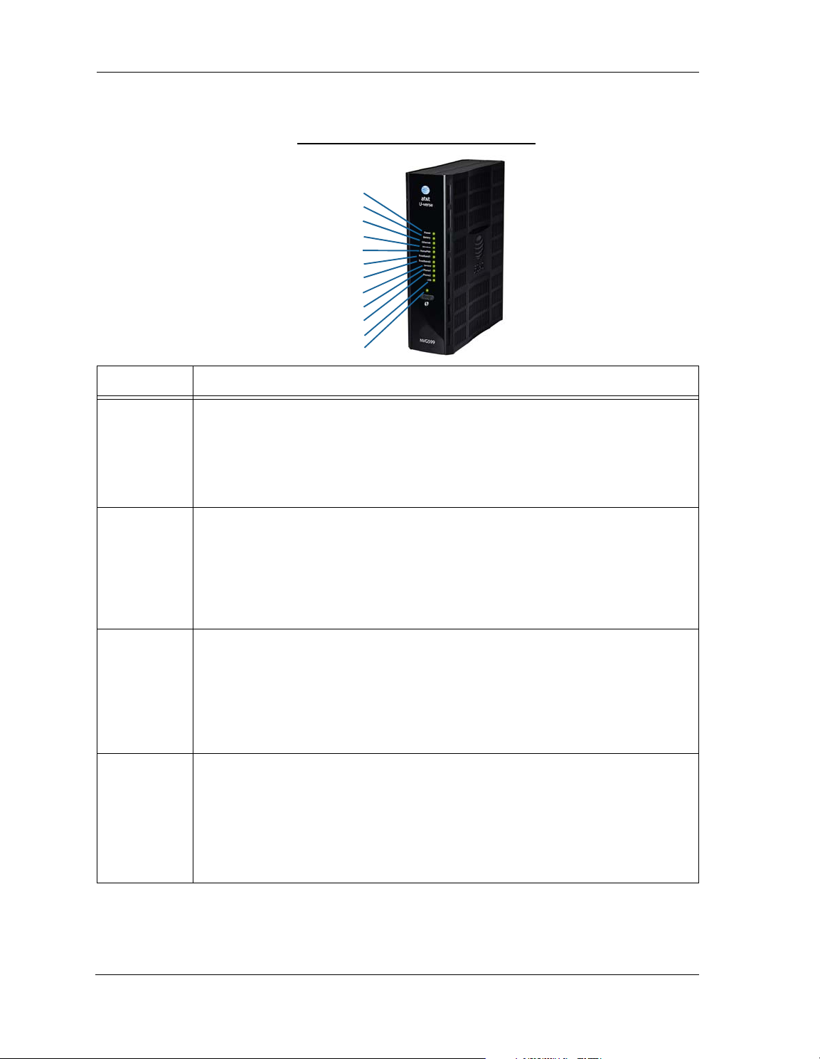
Status Indicator Lights
Side View
Power
Battery
Ethernet
WiFi
HomePNA
USB
Broadband 1
Broadband 2
Service
Phone 1
Phone 2
WPS
Colored LEDs on your NVG599 indicate the activity status of various ports.
ARRIS NVG599 Status Indicator Lights
LED Activity
Solid Green = The device is powered.
Flashing Green = A power-on self-test (POST) is in progress
Power
Flashing Red = A POST failure (not bootable) or device malfunction occurred.
Flashing Amber = Firmware upgrade in progress (see below)
Off = The unit has no AC power. If the battery is in use, the Battery LED will indicate battery status,
and all other LEDs will be off.
Power during
Firmware
Upgrade
All during
Boot process
Battery
During the software installation, you will lose Internet and phone service. The LEDs will function as
follows:
1. As firmware is being loaded into flash, the LEDs operate normally.
2. During the firmware upgrade, which takes a few minutes, the Power LED will flashes amber
(flash writing to memory), and all other LEDs are off.
3. The NVG599 restarts automatically.
As the device reboots, the LEDs display power-on behavior.
• Power LED = Flashing Green
• All other LEDs = Off
If the device does not boot and fails its self-test or fails to perform initial load of the bootloader:
• Power LED = Flashing Red
• ALL other LEDs = Off
If the device boots and then detects a failure:
Power LED = Flashing Green starting POST, and then all LEDs will flash red, including Power LED.
Solid Green = Battery in place but not being used.
Flashing Green = Battery charging.
Solid Red = Battery backup mechanism has a fault.
Flashing Red = Battery needs to be replaced.
Solid Amber = Battery in use.
Flashing Amber = Low battery.
Off = No battery, or battery has no charge.
13
Page 14

Administrator’s Handbook
LED Activity
Solid Green = Powered device connected to the associated port (includes devices with wake-on-LAN
capability where a slight voltage is supplied to the Ethernet connection).
Ethernet
WiFi
HomePNA
Broadband
1**, 2
Flickering Green = Activity seen from devices associated with the port. The flickering of the light is
synchronized to actual data traffic.
Off = The device is not powered, or no cable or no powered devices are connected to the associated
ports.
Solid Green = Wi-Fi is powered.
Flickering Green = Activity seen from devices connected via Wi-Fi. The flickering of the light is syn-
chronized to actual data traffic.
Off = The device is not powered, or no powered devices are connected to the associated ports.
Solid Green = Powered device connected to the associated port (includes devices with wake-on-LAN
capability where a slight voltage is supplied to the Ethernet connection).
Flickering Green = Activity seen from devices associated with the port. The flickering of the light is
synchronized to actual data traffic.
Off = The device is not powered, or no cable or no powered devices are connected to the associated
ports.
Solid Green = Good broadband connection (good DSL sync or Gigabit Ethernet).
Flashing Green = Attempting broadband connection (DSL attempting sync).
Flashing Green and Red = If, after three consecutive minutes, the broadband connection fails to be
established, the LED switches to Flashing Green alternating with a five second steady Red while
attempting or waiting to establish a broadband connection. This pattern continues until the broadband connection is successfully established.
Flashing Red = No DSL signal on the line. This display is not used during times of temporary ‘no tone’
during the training sequence.
Off = The device is not powered.
** Broadband 1 LED is also the Gigabit Ethernet WAN LED when that is in play (and DSL is not).
14
Service
Phone 1, 2
USB
Solid Green = IP connected. The device has a WAN IP address from DHCP or 802.1x authentication
and the broadband connection is up.
Flashing Green = Attempting connection, attempting IEEE 802.1X authentication, or attempting to
obtain DHCP information.
Red = Device attempted to become IP connected and failed (no DHCP response, 802.1x authentica-
tion failed, no IP address from IPCP, etc.). The Red state times out after two minutes, and the Service
indicator light returns to the Off state.
Off = The device is not powered or the broadband connection is not present.
Solid Green = The associated VoIP line has been registered with a SIP proxy server.
Flashing Green = Indicates a telephone is off-hook on the associated VoIP line.
Off = VoIP not in use, line not registered, or gateway power off.
Solid Green = Powered device connected to the associated port (includes devices with wake-on-LAN
capability where a slight voltage is supplied to the Ethernet connection).
Flickering Green = Activity seen from devices associated with the port. The flickering of the light is
synchronized to actual data traffic.
Off = The device is not powered, no cable or no powered devices connected to the associated ports.
Page 15
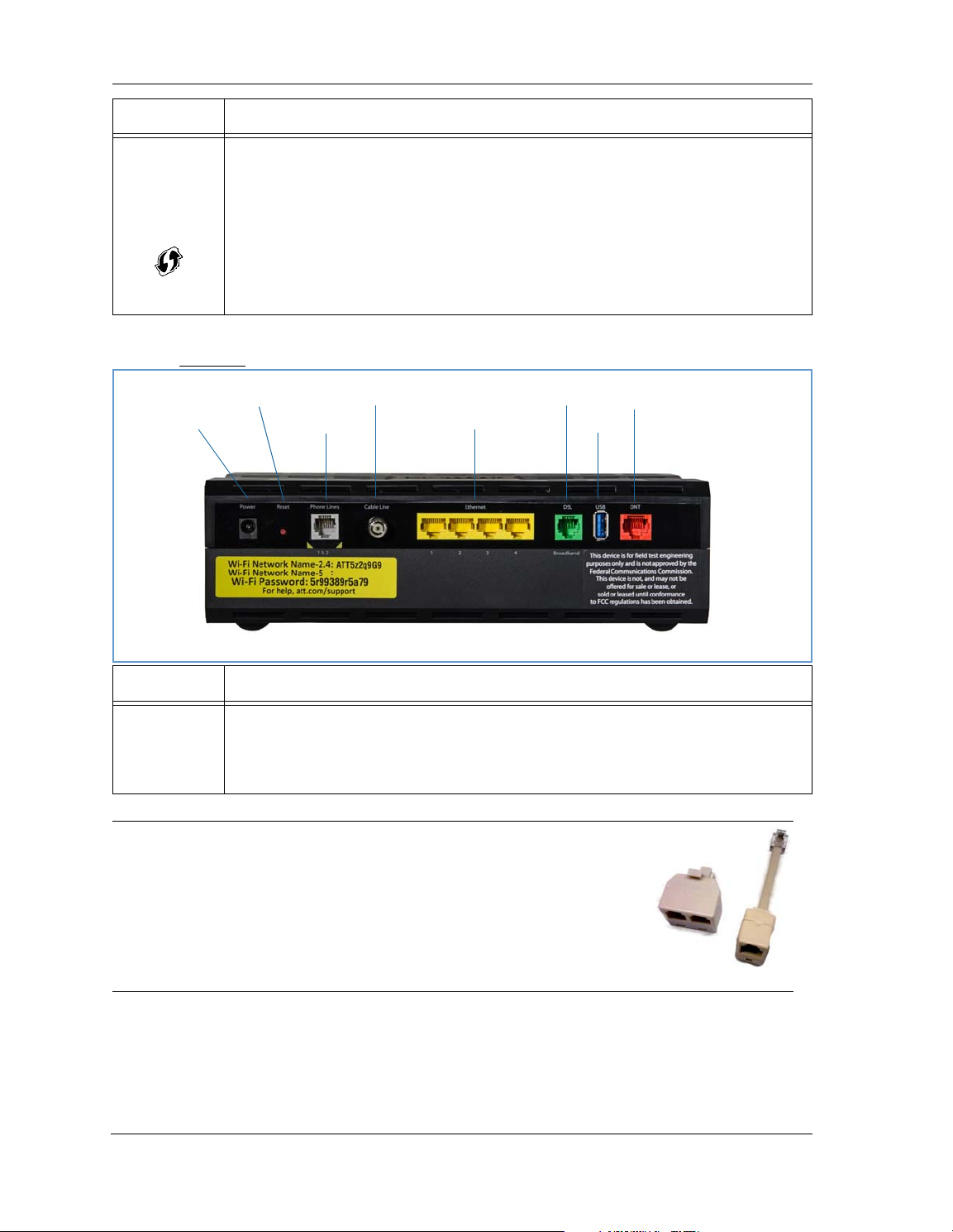
LED Activity
Gigabit Ethernet (WAN)
USB
DSL (WAN)
Ethernet (LAN)
F-Connector (HPNA)
RJ14 (FXS)
Reset
Power Jack
Solid Green = Wi-Fi Protected Setup has been completed successfully. LED should stay on for 5 min-
WPS
(appears after
using WPS
button)
Rear View
utes or until push button is pressed again.
Flashing Green = Continues for 2 minutes, indicating when WPS is broadcasting.
Flashing Red = Continues for 2 minutes, indicating a Session overlap was detected (possible security
risk).
Solid Red = Error unrelated to security, such as failure to find a partner, or WPS is disabled. LED
should stay solid red for 5 minutes or until push button is pressed again.
Off = The device is not powered, or no cable or no powered devices are connected to the associated
ports.
LED Activity
Flashing Amber = A Gigabit Ethernet device is connected to each port.
Ethernet
1, 2, 3, 4
Solid Green = A 10/100 Ethernet device is connected.
Flickering Green = Ethernet traffic activity.
Off = The device is not powered, or no powered devices are connected to the associated ports.
NOTE:
The NVG599 supports two VoIP lines over one RJ14 (FXS) VoIP port. In order to
connect two phone lines, the supplied inner/outer pair splitter adapters must
be attached to the RJ14 (FXS) VoIP port in order to terminate both lines. This is
a special-purpose splitter. You must use only the inner/outer pair splitter
adapters supplied by AT&T.
15
Page 16
Administrator’s Handbook
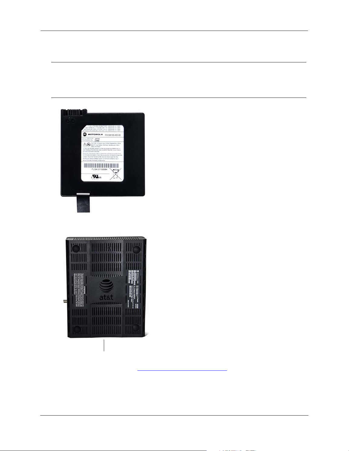
Battery Compartment Door
Battery Installation (optional)
The optional backup battery is located in a compartment on the bottom of the unit. Installing the battery door
requires some care.
CAUTION:
1. Note the tab on the bottom of the battery.
The battery used in this device may present a risk of fire or chemical burn if mistreated. Do not disassemble,
heat above manufacturer’s maximum temperature limit, or incinerate. Replace battery with ARRIS P/N
586185-002-00 only. Use of another battery may present a risk of fire or explosion.
Dispose of used battery promptly. Keep away from children. Do not disassemble and do not dispose of in fire.
2. Insert the battery into the compartment on the bottom of the unit, as shown, and press into place so that
the battery contacts seat securely in the unit.
3. Close the compartment door. See “
Battery Door Instructions” on page 17.
16
Page 17

Battery Door Instructions
Figure 1
Figure 2
Figure 3
1. Place NVG599 unit on a tabletop with the battery door side up.
2. Push in and upward to open the battery door as shown in Figure 1.
3. Swing back the battery door. See Figure 2.
4. Insert the battery in the compartment as shown in Figure 3.
5. Swing the door back down and snap closed.
17
Page 18
Administrator’s Handbook
Windows 7 Windows XP
Set up the ARRIS Gateway
Refer to your Quick Start Guide for instructions on how to connect your NVG599 to your power source, PC, or
local area network, and your Internet access point, whether it is a dedicated DSL outlet or a DSL or cable
modem. Be sure to enable dynamic addressing on your PC. To set up the gateway, complete the following
steps:
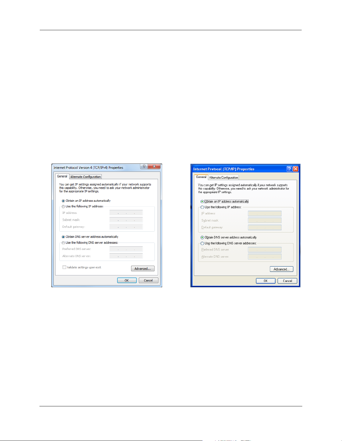
Microsoft Windows:
1. Navigate to the TCP/IP Properties control panel to configure the IP address using one of the suggested pathways that follow. Note that Windows Vista and Windows 7 obtain an IP address automatically by default.
You may not need to configure it at all.
Windows 7 follows a path like this: Start menu -> Control Panel -> Network and Sharing Center -> Change
adapter settings -> Local Area Connection -> Change settings of this connection -> Local Area Connection
Properties -> Internet Protocol (TCP/IP) -> Properties
Windows XP follows a path like this: Start menu -> Settings -> Control Panel -> Network Connections -> Local
Area Connection -> Internet Protocol [TCP/IP] -> Properties
2. Select Obtain an IP address automatically.
3. Select Obtain DNS server address automatically, if available.
4. Remove any previously configured gateways, if available.
5. OK the settings. Restart if prompted.
To ch e ck :
1. Open the Networking control panel and select Internet Protocol Version 4 (TCP/IPv4).
2. Click the Properties button. The Internet Protocol Version 4 (TCP/IPv4) Properties window should appear as
shown.
18
Page 19
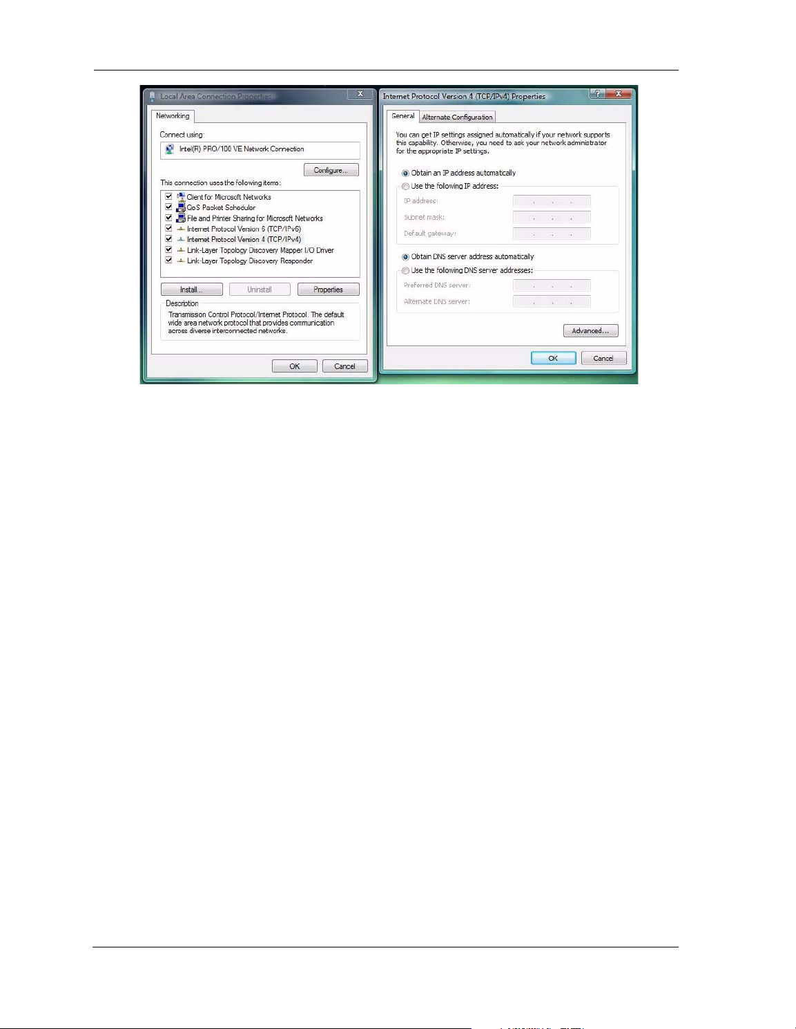
3. Set the radio buttons to the values shown above, and click the OK button.
Windows Vista
19
Page 20
Administrator’s Handbook
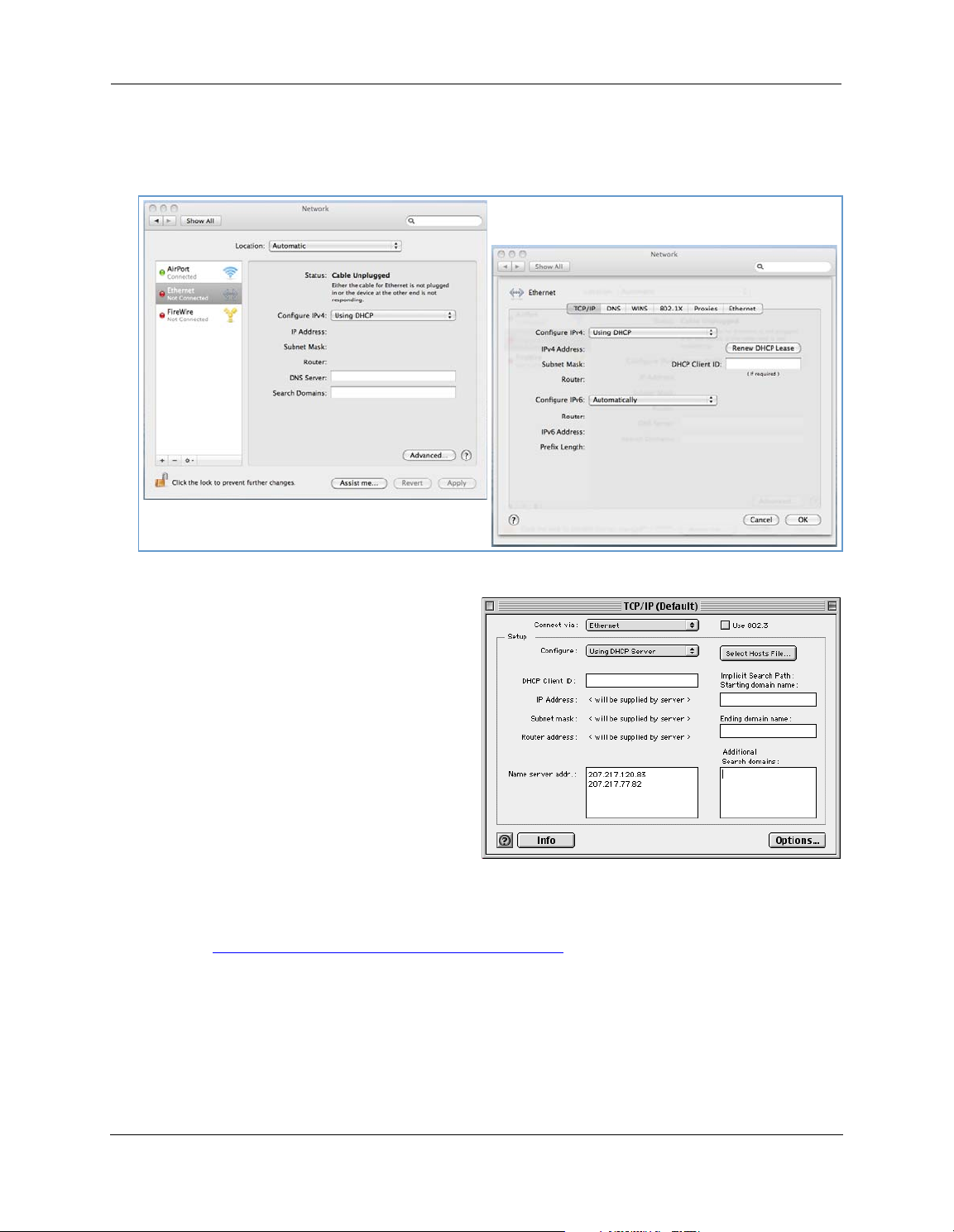
Macintosh MacOS 8 or higher or Mac OS X:
1. Access the TCP/IP or Network control panel.
Mac OS X follows a path like this:
Apple Menu -> System Preferences -> Network
MacOS Classic follows a path like this:
Apple Menu -> Control Panels -> TCP/IP Control
Panel
2. Select Ethernet.
3. Select Configure Using DHCP.
4. Close and save, if prompted.
Proceed to “
Accessing the Web Management Interface” on page 21.
20
Page 21
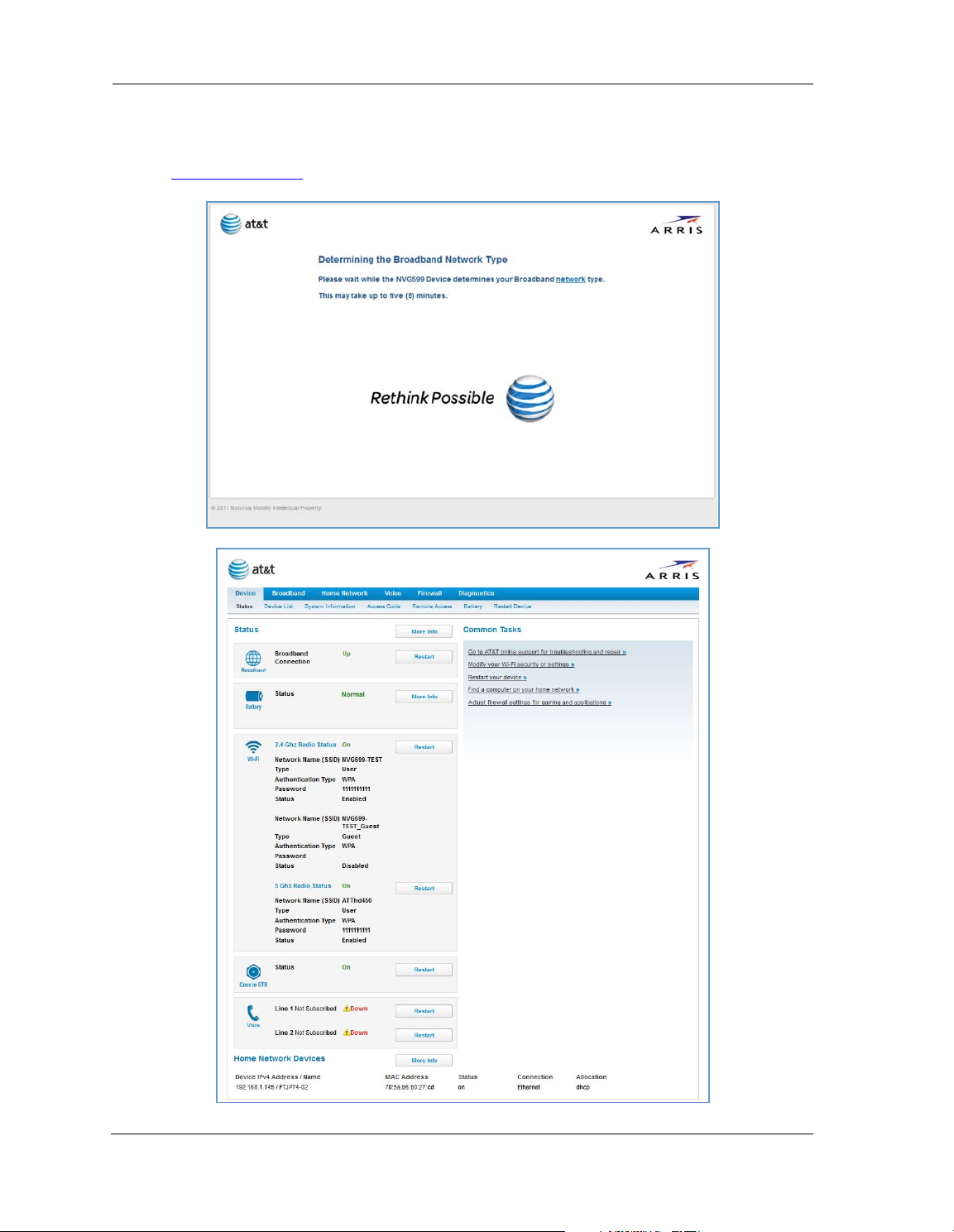
Accessing the Web Management Interface
1. Run your Web browser application, such as Firefox or Microsoft Internet Explorer, from the computer connected to the NVG599 device.
2. Enter http://192.168.1.254
While the NVG599 is determining the broadband network type, the following screen appears.
The Device Status page appears.
in the Location text box.
21
Page 22
Administrator’s Handbook
3. Check to make sure the Broadband and Service LEDs on your NVG599 device are lit
connection to the Internet is active.
Congratulations! Your installation is complete. You can now surf to your favorite Web sites by typing a URL in
your browser’s location box or by selecting one of your favorite Internet bookmarks.
GREEN
to verify that the
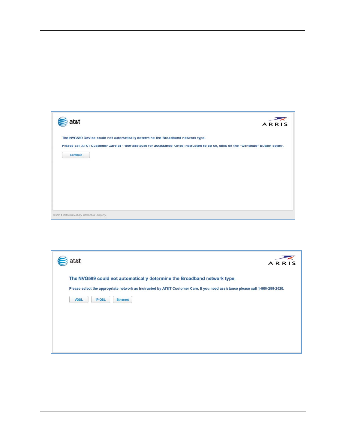
Broadband Network Redirect Pages
After a few minutes, if the broadband network cannot be determined, the following screen appears. Contact
AT&T Customer Care at the number shown on your screen for assistance.
If you click the Continue button, the following screen appears. Here you can manually select the broadband
network type, if you know it.
22
Page 23
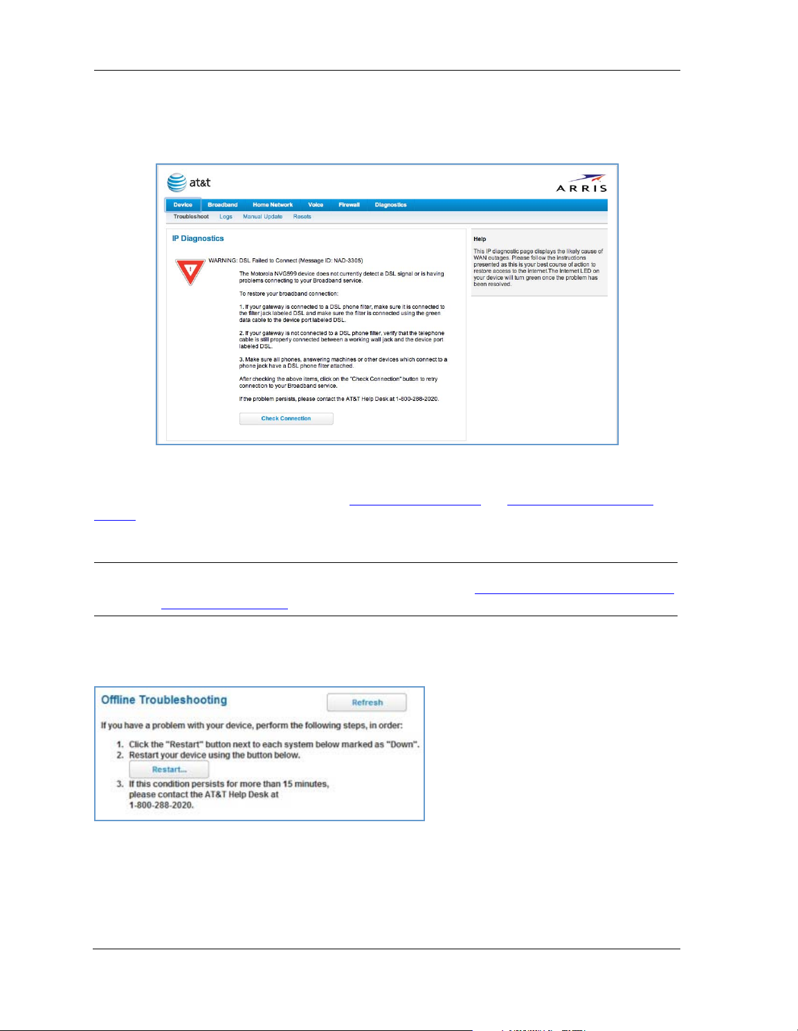
IP Diagnostics Page Redirect
In the event that your connection to the Internet fails, the
RED
and you are redirected to the
Follow the on-screen troubleshooting suggestions.
For additional troubleshooting information, see “
page 87.
IP Diagnostics
page.
Diagnostics” on page 78 and “Basic Troubleshooting” on
Broadband LED
on your NVG599 device flashes
When your connection is restored or the problem is resolved, the
NOTE:
For AT&T this function is enabled by default. See the CLI command
[ off | on ]” on page 149.
Broadband LED
“set management lan-redirect enable
Offline Troubleshooting
If the WAN is down, the following information is displayed at the top of the page:
turns
GREEN
.
23
Page 24
Administrator’s Handbook
Device Status Page
After you have performed the basic Easy Login configuration, any time you log in to your NVG599 you will
access the NVG599 Home page.
To access the Home page, type http://192.168.1.254 in your Web browser’s location box.
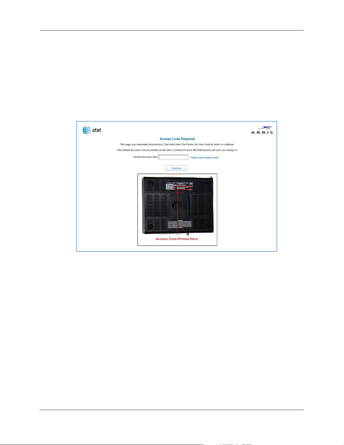
Device Access Code
On the Device Status page, you may be required to provide your device access code to access the Web
management configuration pages. The device access code is unique to your device. It is printed on a label on
the side of the NVG599.
Enter your device access code and click the
24
Continue
button.
Page 25
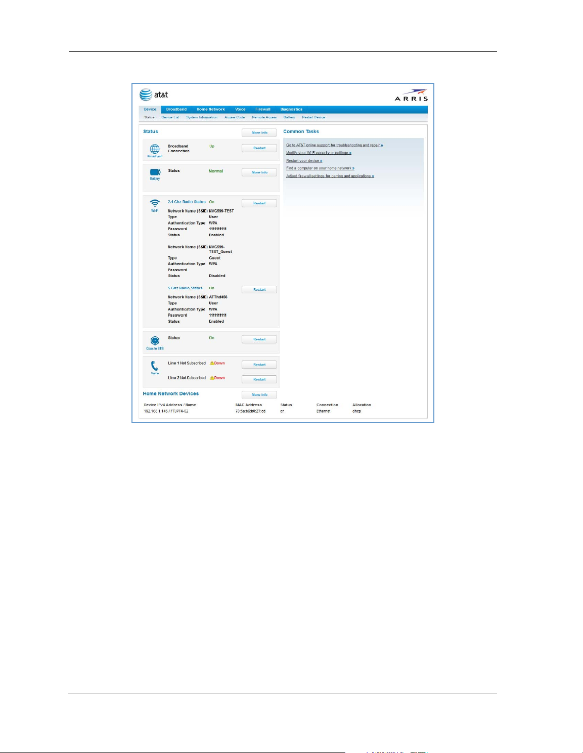
The Device Status page appears.
DeviceStatusWindow
25
Page 26
Administrator’s Handbook
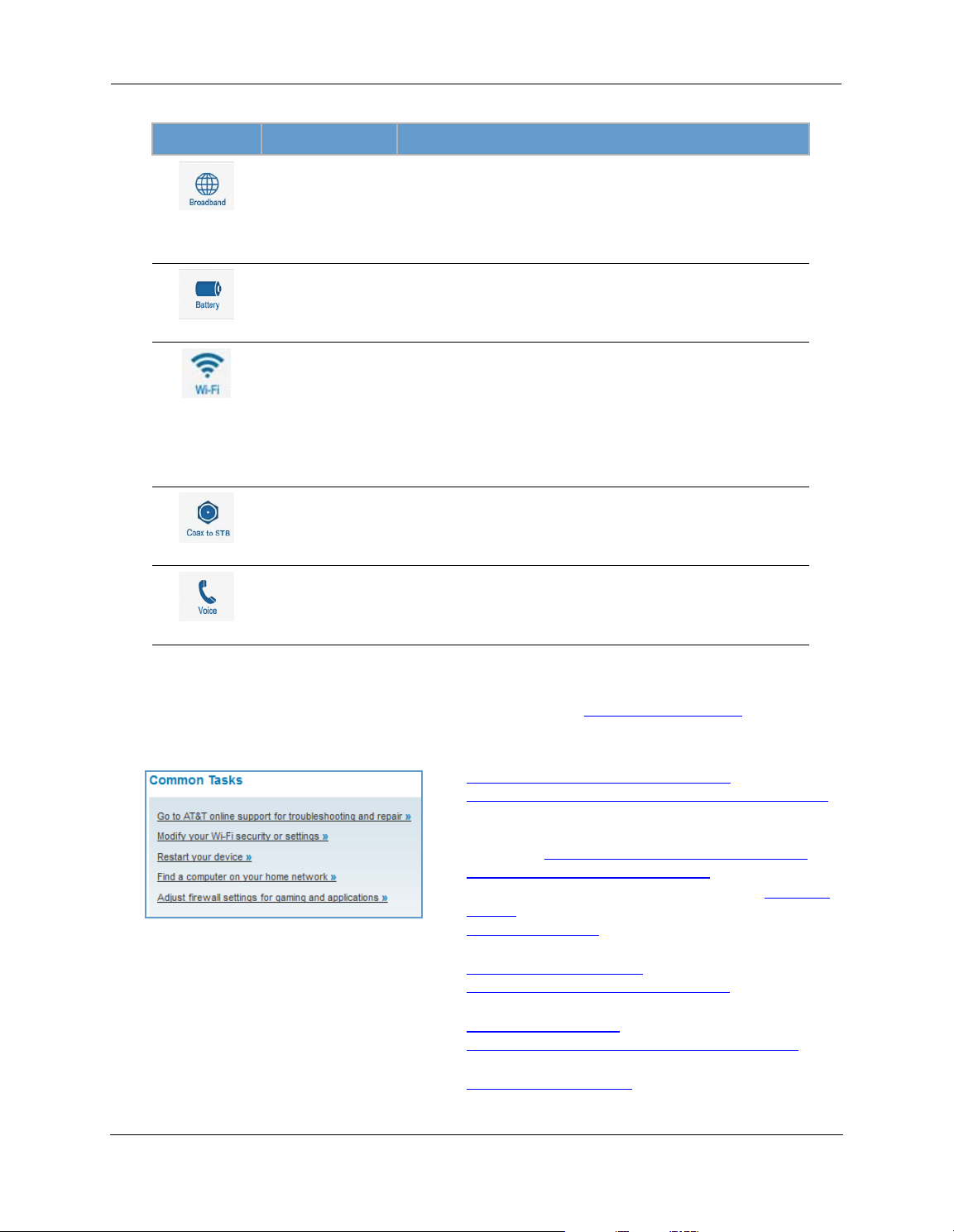
The Device Status page displays the following information in the center section:
(icon) Field Description
Broadband
Connection
(Broadband)
Status May display any of these values: Normal, Low Battery,
(Battery)
Status Your wireless signal may be On or Off.
Network ID (SSID) The name or ID that is displayed to a client scan. The default SSID for
(WiFi)
Authentication Type The type of wireless encryption security in use. May be Disabled,
Network Key Wireless network encryption key in use.
Status Off or On.
Waiting for DSL is displayed while the NVG599 is training. This
should change to Up within two minutes.
Up is displayed when the ADSL line is synched and the session is
established.
Down indicates inability to establish a connection; possible line failure.
Charging, Warning: No battery or battery has no
charge or Warning: Battery backup mechanism has a
fault.
the NVG599 is attxxx where xxx is the last 3 digits of the serial
number located on the side of the NVG599.
WPA, WEP, Default Key, or Manual.
(Coax to STB)
Line 1 Indication of VoIP or other phone connection.
Line 2 Indication of VoIP or other phone connection.
(Voice)
Some fields may or may not be displayed, depending on your particular setup.
Diagnostics
The
button will connect you to the
Troubleshoot
page. See “Diagnostics” on page 78.
The frame at right displays some links to commonly performed tasks for easy access.
Display additional troubleshooting steps » - OR -
Go to AT&T online support for troubleshooting and repair
This link will connect you to the IP Diagnostics page with
help for troubleshooting and the AT&T Help Desk information. See “
IP Diagnostics Page Redirect” on page 23.
Modify your WiFi security or settings »
This link will connect you to the
page 43.
Restart your device »
This link will connect you to the Restart Device page. See
“
Restart Device” on page 33.
Find a computer on your home network »
This link will connect you to the Device List page. See
“
Device List” on page 28.
Adjust firewall settings for gaming and applications »
This link will connect you to the NAT/Gaming page. See
“
NAT/Gaming” on page 67.
WiFi
page. See “WiFi” on
26
Page 27
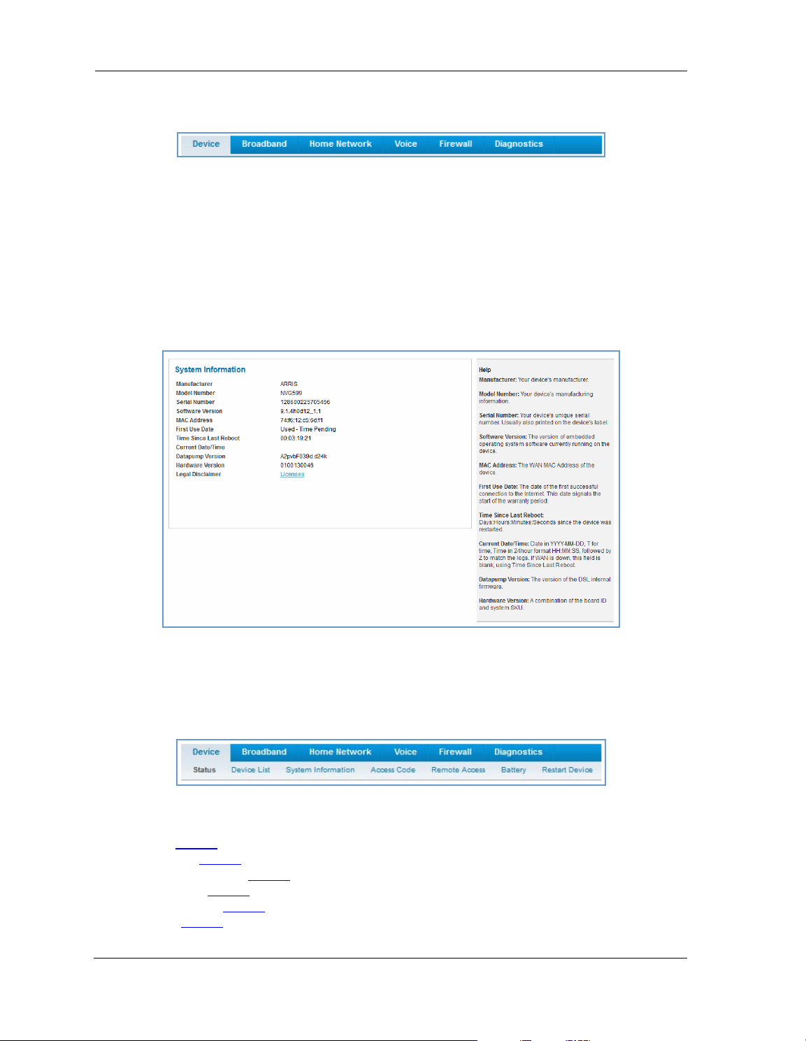
Tab B ar
The tab bar is located at the top of every page, allowing you to move freely about the site.
The tabs reveal a succession of pages that allow you to manage or configure several features of your Gateway.
Each tab is described in its own section.
Help
Online Help for your device is available in the rightmost frame on every page in the Web interface. For
example, the Help section at right is displayed on the System Information page.
Links Bar
The links bar appears at the top of each page, allowing you to configure aspects of the features displayed on
the page. For example, the links bar on the Home Summary page is as shown below:
The links bar on the Device Status page includes the following links. For more information about each link, see
the related section in this guide.
Status (see page 24
Device List (see page 28
System Information (see page 29
Access Code (see page 30
Remote Access (see page 31
Battery (see page 32
)
)
)
)
)
)
27
Page 28
Administrator’s Handbook
Restart Device (see page 33)
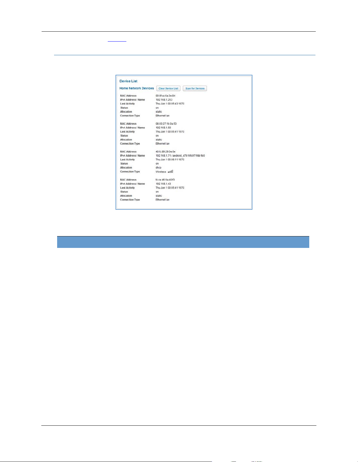
Link: Device List
When you click the
Device List
link, the Device List page appears.
The page displays the following summary information for each home network device connected to the NVG599
device on your local area network: IPv4 address, network name, MAC address, and other status information.
Home Network Devices
MAC Address Client device’s unique hardware address.
IPv4 Address / Name Client device’s IP address or device network name.
Last Activity Date and time of last traffic for this client device.
Status May be off or on.
Allocation Type of IP address assignment, for example, static or DHCP.
Connection Type Type of connection, for example, Ethernet or WiFi.
28
Page 29
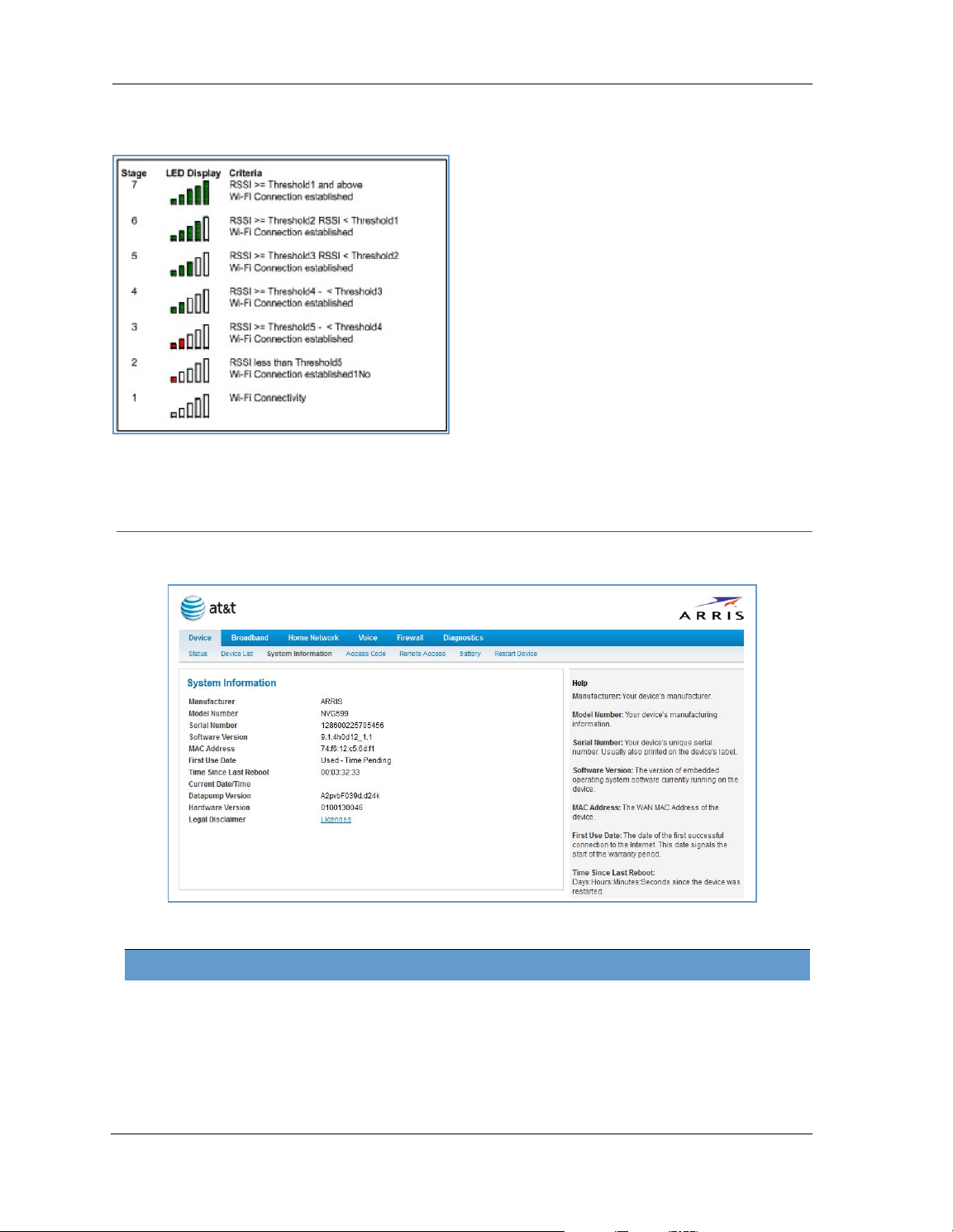
For WiFi client connections, the Device List page displays the familiar bars indicating signal strength, as
follows:
Click the
Click the
Clear Device List
Scan for Devices
button to update the Home Network Devices summary.
button to seek out other devices that have been connected since the last Home
Network Devices summary update.
Link: System Information
When you click the
The page displays the following information:
System Information
link, the System Information page appears.
System Information
Manufacturer Manufacturer’s identifier name.
Model Number Manufacturer’s model number.
Serial Number Unique serial number of your device.
Software Version Version number of the current embedded software in your device.
MAC Address Unique hardware address of this NVG599 unit.
29
Page 30
Administrator’s Handbook
First Use Date Date and time the NVG599 device is first used. This field changes to the current date
and time after a reset to factory defaults.
Time Since Last Reboot Elapsed time since last reboot of the device in days:hr:min:sec.
Current Date/Time Current system date and time in days:hr:min:sec.
Datapump Version Underlying operating system software datapump version.
Legal Disclaimer Clicking the Licenses link displays a listing of software copyright attributions, also
shown in
“Copyright Acknowledgments” on page 189
.
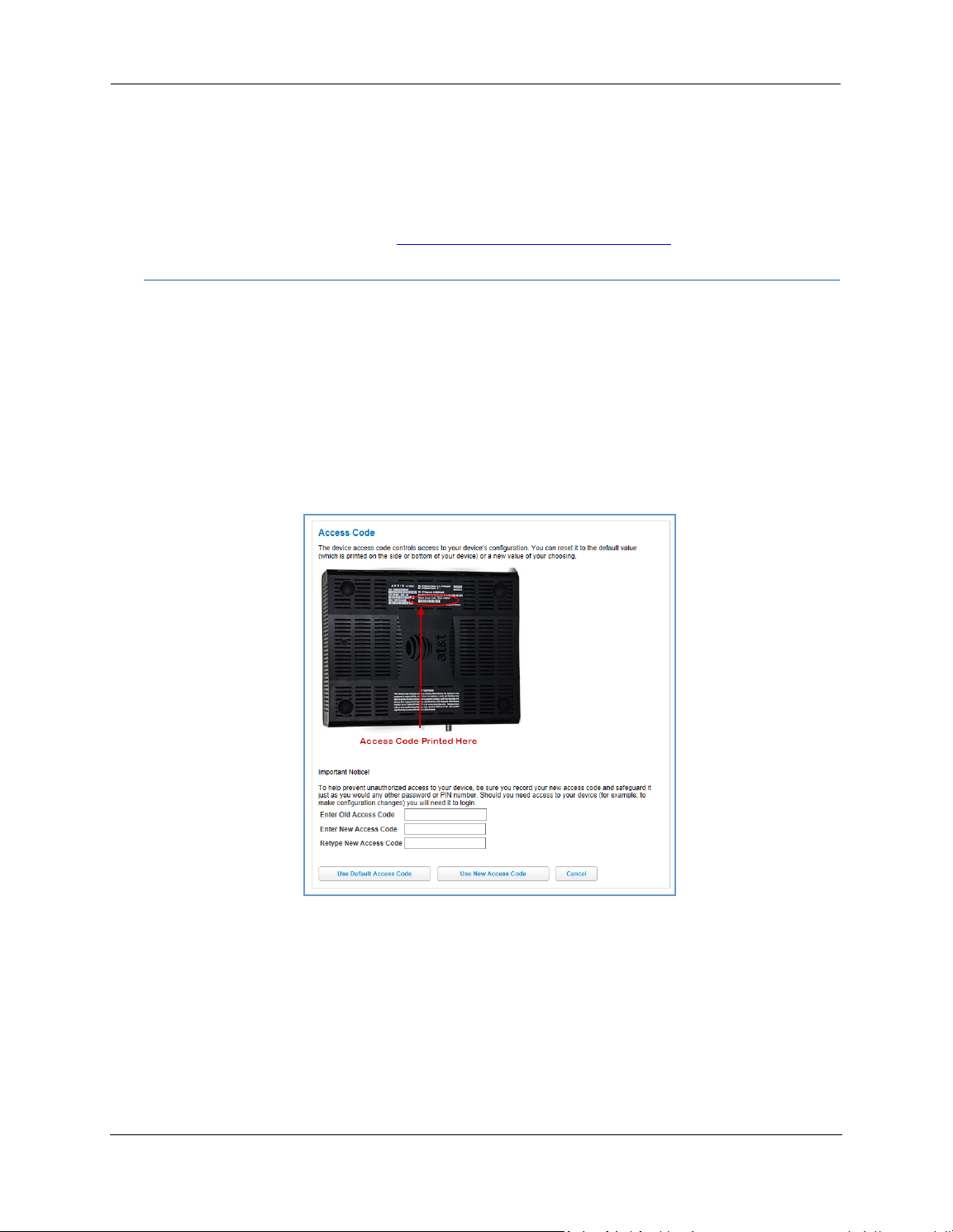
Link: Access Code
When you click the Access Code link, the Access Code page appears and allows changes to the code that
controls access to your device’s configuration. Access to your NVG599 device is controlled through an account
named Admin. The default Admin password for your device is the unique access code printed on the label on
the side of your device.
As the Admin, you can change this password to one of your own choosing between 8 and 20 characters long.
The new password must include two characters from any these categories: alpha, number, and special
characters.
Example
: “fru1tfl13s_likeabanana”
Enter your old access code, your new access code, and click the
code takes effect immediately.
You can always return to the original default password by clicking the
30
Use New Access Code
Use Default Access Code
button. The new access
button.
Page 31

Link: Remote Access
The Remote Access page lets you grant access to your NVG599 device to other users on the WAN. This
function can be used for advanced troubleshooting or remote configuration.
WAR NING:
If remote access is not currently enabled, the Remote Access page will let you configure and enable it. If
remote access has been enabled, the Remote Access page will indicate that, and provides a button to disable
it.
Enabling remote access allows anyone who knows or can determine the password, port ID, and URL
(address) of your NVG599 device to view any configuration settings or change the operation of your gateway.
To enable remote access:
1. Type a password in the Password field. This password must be at least 8 characters long, and must include at
least two of the following types of characters:
Alphabetic (letter) characters
Numeric (number) characters
Special characters (! @ # $ % ^ & * , etc)
2. If necessary, set a custom port number for secure HTTP access to the NVG599 remote access session in the
Port Value field.
3. Click the radio button that describes the type of remote access to allow:
Read only access - to allow the remote access session to view, but not change, the configuration and col-
lected statistics of the gateway.
Update access - to allow the session to make changes to the gateway’s configuration.
4. Click the
The NVG599 updates the Remote Access page and displays the current remote access settings, shows the URL
that a remote access client must use to connect to the remote access session, and provides a button for ending
the remote access session. The remote access client will need to connect to the URL shown on the Remote
Access page, and will need to log in with the user name “tech” and with the password configured when access
was enabled.
Enable Remote Access
button.
31
Page 32

Administrator’s Handbook
To end (disable) an existing remote access configuration, click the
below:
Disable Remote Access
button, as shown
Link: Battery
The Battery page shows the condition and status of the NVG599 internal battery, and provides control over the
battery condition audible alarm.
The battery condition audible alarm provides an on-hook ringing signal on a connected telephone if the
NVG599 battery needs recharging or replacing. This alarm uses a distinctive “splash” ring pattern and a battery
notification message on phones with caller ID displays or announcers. Additionally, the NVG599 provides an
off-hook voice notification to the subscriber if the NVG599 battery is low (and needs recharging) or faulty (and
needs replacing). After playing the recorded voice notification, the NVG599 provides a dial tone.
The alarm is triggered when the NVG599 determines that the installed battery is:
Below 35% charge and in need of recharging, or
Unable to charge past 80% of capacity and in need of replacing.
Note:
To change the alarm setting, click the Battery Audible Alert drop-down menu, and select the setting (On or Off)
for the alarm. Click the
A subscriber may interrupt the voice notification by dialing. The voice notification may be turned off by a
subscriber phone dialing “*#103”. This capability is included in the VOIP digit map with the parameter
*#103<:@C06>
Save
button to save the new settings, or
Cancel
to discard them.
32
Page 33

Link: Restart Device
When the NVG599 is restarted, it will disconnect all users, initialize all its interfaces, and load the operating
system software.
In some cases, when you make configuration changes, you may be required to restart for the changes to take
effect.
33
Page 34

Administrator’s Handbook
Broadband Tab
Links available on the Broadband tab provide access to pages that allow you to view information about the
broadband connection and configure connection details.
Link: Broadband Status
When you click the
Broadband
tab, the Broadband
Status
page is the first to appear.
34
Page 35

Status
The
page displays information about the NVG599 device’s WAN connection(s) to the Internet.
Broadband Status
Broadband Connection
Source
Broadband Connection May be Up (connected) or Down (disconnected).
Broadband IPv4 Address The public IP address of your device, whether dynamically or statically assigned.
Gateway IPv4 Address Your ISP's gateway router IP address.
MAC Address Your device’s unique hardware address identifier.
Primary DNS The IP address of the primary Domain Name System (DNS) server.
Secondary DNS The IP address of the backup DNS server, if available.
Primary DNS Name The name of the primary DNS server.
Secondary DNS Name The name of the backup DNS server, if available.
MTU Maximum transmittable unit before packets are broken into multiple packets.
The communications technology providing the NVG599 broadband uplink.
DSL Status (for each line)
Line State May be Up (connected) or Down (disconnected).
Downstream Sync Rate The rate at which your connection can download (receive) data on your DSL line, in
kilobits per second.
Upstream Sync Rate The rate at which your connection can upload (send) data on your DSL line, in kilobits
per second.
Modulation Method of regulating the DSL signal. DMT (discrete multi-tone) allows connections to
work better when certain radio transmitters are present.
Data Path Type of path used by the device's processor.
Downstream and Upstream Statistics (DSL WAN)
SN Margin (db) Signal-to-noise margin, in decibels. Reflects the amount of unwanted noise on the DSL
line.
Line Attenuation Amount of reduction in signal strength on the DSL line, in decibels.
Output Power (dBm) Measure of power output in decibels (dB) referenced to one milliwatt (mW).
Errored Seconds The number of uncorrected seconds after being down for seven consecutive seconds.
35
Page 36

Administrator’s Handbook
Loss of Signal The absence of any signal for any reason, such as a disconnected cable or loss of
power.
Loss of Frame A signal is detected but the device cannot sync with signal because of mismatched
protocols, wrong ISP connection configuration, or faulty cable.
FEC Errors Forwarded Error Correction errors. Count of received errored packets that were fixed
successfully without a retry.
CRC Errors Number of times data packets have had to be resent because of errors in transmission
or reception.
Ethernet Statistics (Ethernet WAN)
Line State Up or Down
Current Speed Line speed
Current Duplex Full- or half-duplex
Receive Packets Number of packets received
Transmit Packets Number of packets sent
Receive Bytes Number of bytes received
Transmit Bytes Number of bytes sent
Receive Unicast Receive Unicast statistics
Transmit Unicast Transmit Unicast statistics
Receive Multicast Receive Multicast statistics
Transmit Multicast Transmit Multicast statistics
Receive Drops Received packets dropped
Transmit Drops Sent packets dropped
Receive Errors Count of received errored packets that were fixed successfully without a retry.
Transmit Errors Number of times data packets have had to be resent due to errors in transmission.
Collisions Count of packet collisions.
Aggregated Information
Bonded Downstream Rate The bonded channel receive rate.
Bonded Upstream Rate The bonded channel transmit rate.
IPv6
Status May be Enabled or Unavailable.
Global Unicast IPv6 Address The public IPv6 address of your device, whether dynamically or statically assigned.
Border Relay IPv4 Address The public IPv4 address of your device.
IPv4 Statistics
Transmit Packets IPv4 packets transmitted.
Transmit Errors Errors on IPv4 packets transmitted.
Transmit Discards IPv4 packets dropped.
IPv6 Statistics
Transmit Packets IPv6 packets transmitted.
Transmit Errors Errors on IPv6 packets transmitted.
Transmit Discards IPv6 packets dropped.
36
Page 37

Link: Configure
When you click the
type of broadband connection should it change in the future.
Broadband Source Override
(Bonded), or Ethernet WAN.
If you switch from DSL to Ethernet or from Ethernet to DSL, the device will prcoceed to reconnect as in its initial connection to the Internet, as described earlier. See “
page 21.
The WAN connection is automatically configured. However, you can adjust the
(maximum transmittable unit) value, if your service provider suggests it. The default 1500 is the maximum
value, but some services require other values (1492 is common).
Configure
link, the Broadband
Configure
screen appears. Here you can reconfigure your
- Auto (automatically detected), DSL - Line 1, DSL - Line 2, DSL - Line 1 / Line -2
Accessing the Web Management Interface” on
Maximum allowable MTU
If you make any change here, click the
Save
button.
37
Page 38

Administrator’s Handbook
Link: IGMP Stats
When you click the
proxy groups and multicast forwarding information. It also displays a packet counter.
IGMP Stats
link, the
IGMP Stats
screen appears. The IGMP statistics screen reports IGMP
38
Page 39

Home Network Tab
When you click the
Home Network
tab, the Home Network Status page appears.
The Home Network Status page displays information
about the NVG599 device’s local area network.
If you click the
device will generate statistics for each of the 11
channels available, displaying:
Channel number
AP (access point) count
Congestion score (1 - 10) - Note that higher val-
ues mean lower congestion.
The wireless congestion feature provides simple data
to the user to show the level of network congestion
in each wireless channel. This data can be used to
determine router placement or to determine which
channels to avoid.
The display tells the user how many access points
(APs) are active within each channel, and provides a
score of 1 - 10 to indicate how clear the channel is. A
higher score indicates less congestion in a channel;
thus, a 10 indicates a channel extremely clear of
wireless traffic and noise. Alternatively, a score of 1
indicates more severe congestion in a channel.
You can clear the current statistics information by
clicking the
Run Congestion Detection
Clear Statistics
button.
button, the
39
Page 40

Administrator’s Handbook
Home Network Status
Device IPv4 Address The NVG599 device’s own IP address on the network.
DHCP Netmask The device’s own netmask on the network.
DHCPv4 Start Address The starting IP address of the DHCP range served by the device.
DHCPv4 End Address The ending IP address of the DHCP range served by the device.
DHCP Leases Available The number of IP addresses of the DHCP range available to be served by the device.
DHCP Leases Allocated The number of IP addresses of the DHCP range currently being served by the device.
DHCP Primary Pool Source pool of the IP addresses served by the NVG599 device, Public or Private.
IPv6
Status May be Enabled or Unavailable.
Global IPv6 Address The public IPv6 address of your device, whether dynamically or statically assigned.
Link-local IPv6 Address The private IPv6 address of your device, whether dynamically or statically assigned.
Router Advertisement Prefix The IPv6 prefix to include in router advertisements.
IPv6 Delegated LAN Prefix The IPv6 network address prefix that identifies the NVG599 network.
IPv4 Statistics
Transmit Packets IPv4 packets transmitted.
Transmit Errors Errors on IPv4 packets transmitted.
Transmit Discards IPv4 packets dropped.
IPv6 Statistics
Transmit Packets IPv6 packets transmitted.
Transmit Errors Errors on IPv6 packets transmitted.
Transmit Discards IPv6 packets dropped.
WiFi Status
WiFi Radio Status Status of the Wi-Fi radio: Enabled or Disabled.
Mode May be 802.11B only, 802.11G only, 802.11N only, 802.11 B/G or 802.11 B/G/N. For
the 5.0 Ghz radio, may be 802.11AC as well.
Bandwidth The capacity of the wireless LAN to carry traffic in megahertz.
Current Radio Channel The radio channel that your Wi-Fi network is broadcasting on.
Radio Channel Selection May be set to automatic or manually selected.
MAC Address Filtering May be either On or Off. If On, you can accept or block client devices from your WLAN
based on their MAC address.
Power Level May be adjusted up to 100%, lower if multiple wireless access points are in use, and
might interfere with each other.
WiFi MAC Address Shows the information of the MAC address of the wireless subsystem.
User SSID May be either On or Off for either frequency.
Guest SSID May be either On or Off for the 2.4 Ghz radio only.
Network Name (SSID) The name or ID that is displayed to a client scan. The default SSID for the NVG599 is
attxxx where xxx is the last 3 digits of the serial number located on the side of the
NVG599 device.
Hide SSID May be either On or Off. If On, your SSID will not appear in a client scan.
Wireless Security The type of wireless encryption security in use. May be Disabled, WPA, WEP,
Default Key, or Manual.
40
Page 41

Password Shows the information of the security encryption key in use.
WiFi Network Statistics
Transmit Bytes Number of bytes transmitted on the Wi-Fi network.
Receive Bytes Number of bytes received on the Wi-Fi network.
Transmit Packets Number of packets transmitted on the Wi-Fi network.
Receive Packets Number of packets received on the Wi-Fi network.
Transmit Error Packets The number of errors on packets transmitted on the Wi-Fi network.
Receive Error Packets The number of errors on packets received on the Wi-Fi network.
Transmit Discard Packets The number of packets transmitted on the Wi-Fi network that were dropped.
Receive Discard Packets The number of packets received on the Wi-Fi network that were dropped.
LAN Ethernet Statistics
State May be Up or Down.
Transmit Speed The maximum speed of which the port is capable.
Transmit Packets The number of packets sent out from the port.
Transmit Bytes The number of bytes sent out from the port.
Transmit Dropped The number of packets sent out from the port that were dropped.
Transmit Errors The number of errors on packets sent out from the port.
Receive Packets The number of packets received on the port.
Receive Bytes The number of bytes received on the port.
Receive Unicast The number of unicast packets received on the port.
Receive Multicast The number of multicast packets received on the port.
Receive Dropped The number of packets received on the port that were dropped.
Receive Errors The number of errors on packets received on the port.
The links at the top of the Home Network page provide access to a series of pages that allow you to configure
and monitor features of your device.
The links bar on the Home Network page includes the following links. For more information about each link,
see the related section in this guide.
Configure (see page 42
HPNA Configure (see page 42
Wifi (see page 43
MAC Filtering (see page 46
Wireless Scan (see page 47
Subnets & DHCP (see page 47
IP Allocation (see page 49
HPNA (see page 51
)
)
)
)
)
)
)
)
41
Page 42

Administrator’s Handbook
Link: Configure
When you click the
For each Ethernet Port, 1 through 4, you can select:
Ethernet
full- or half-duplex.
MDI-X
– Auto (the default self-sensing crossover setting), Off, or On.
Click the
Save
Configure
link, the
Configure
page for the Ethernet LAN appears.
– Auto (the default self-sensing rate), 10M full- or half-duplex, 100M full- or half-duplex, or 1G
button.
Link: HPNA Configure
When you click the
HPNA Configure
link, the
HPNA Configure
page for the HomePNA network appears.
On
Here you can set HomePNA Networking
or
If desired, you can also set the Output Jack, as either the
Save
Click the
button.
42
Off
.
Coax
jack or the
Phone
jack.
Page 43

Link: WiFi
When you click the
elements.
WiFi
link, the WiFi page appears. The WiFi page displays the status of your wireless LAN
The WiFi page center section contains a summary of the configuration settings and operational status for the
wireless access point.
Summary Information
Field Status and/or Description
Radio Selection Display the settings for either the 2.4 Ghz or the 5.0 Ghz frequency radio.
WiFi Operation May be either On or Off.
Mode Wireless transmission mode. For the 2.4 Ghz radio, may be 802.11B only, 802.11G only,
802.11N only, 802.11 B/G or 802.11 B/G/N. For the 5.0 Ghz radio, may be 802.11AC as
well.
Bandwidth The capacity of the wireless LAN to carry traffic in megahertz, 20 or 40.
Channel The radio channel on which your Wi-Fi network is broadcasting.
Power Level May be adjusted up to 100%, lower if multiple wireless access points are in use, and
might interfere with each other.
User SSID Enable May be either On or Off for either frequency.
Guest SSID Enable May be either On or Off for the 2.4 Ghz radio only.
Network Name (SSID) The name or ID that is displayed to a client scan. The default SSID for the NVG599 is
attxxx where xxx is the last 3 digits of the serial number located on the side of the
device.
Hide SSID May be either Off or On. If On, your SSID will not appear in a client scan.
Security The type of wireless encryption security in use. May be OFF-No Privacy, WPA-
PSK, WEP, Default Key or Manual.
43
Page 44

Administrator’s Handbook
WPA Version If WPA is selected, may be Both, WPA-1, or WPA-2.
WEP Key Length May be 10 characters for 40/64-bit, or 26 characters for 128-bit WP encryption.
Key Here you can enter a manual encryption key.
WiFi Protected Setup (WPS) May be either On or Off.
General Information
WiFi Operation
abled, and the wireless access point will not provide or broadcast its wireless LAN services.
Mode
– The drop-down menu allows you to select and lock the NVG599 into the wireless transmission mode
you want: A/C, B/G/N, B-only, B/G, G-only, or N-only.
For compatibility with clients using 802.11b (up to 11 Mbps transmission), 802.11g (up to 20+ Mbps),
802.11a (up to 54 Mbit/s using the 5 GHz band), or 802.11n (from 54 Mbit/s to 600 Mbit/s with the use of
four spatial streams at a channel width of 40 MHz), select B/G/N. To limit your wireless LAN to one mode or
the other, select the option that applies to your setup.
Bandwidth
ting) to increase data speeds. The 40-MHz mode may only be selected if the Mode setting is 801.11 B/G/N
or 802.11 N-Only. To prevent interference with lower bandwidth clients, the wireless network will revert to
20MHz operation if non-compatible (802.11B, 802.11G, or 20-MHz 802.11N) clients are detected.
Channel
quency range within the 2.4-Ghz or 5.0-Ghz band. The Automatic setting allows the wireless access point to
automatically determine the best channel for broadcast.
Power Level
coverage by lowering its radio power output. Default is 100% power. Transmit power settings are useful in
large venues with multiple wireless routers where you want to reuse channels. Since there are only three
non-overlapping channels in the 802.11 spectrum, it helps to size the wireless access point cell to match the
location. This allows you to install a router to cover a small “hole” without conflicting with other routers
nearby.
Network Name (SSID)
entering a freeform name of up to 32 characters, for example “Brian’s Wireless LAN.” In client PC software,
this might also be called the wireless ID. The Network Name is used to identify this particular wireless LAN.
Depending on their operating system or client wireless card, users must either:
• Select from a list of available wireless LANs that appear in a scanned list on their client.
• Enter this name on their clients in order to join this wireless LAN.
Hide SSID
computers. Hiding the SSID prevents casual detection of your wireless network by unwanted neighbors and
passers-by. The gateway WLAN will not appear when clients scan for access points. If Hide SSID is enabled,
you must remember to enter your SSID when adding clients to the wireless LAN.
– Automatically enabled by default. If you deselect the checkbox, the WiFi options are dis-
NOTE:
If you choose to limit the operating mode to 802.11b or 802.11g only, clients using the mode you excluded
will not be able to connect.
– Use a single 20-MHz channel (20MHz setting) , or combine two 20-MHz channels (40MHz set-
– Channel (1 through 11, for North America) on which the network will broadcast. This is a fre-
– Sets the wireless transmit power, scaling down the wireless access point’s wireless transmit
– Preset to a number unique to your unit. You can either leave it as is, or change it by
– If enabled, this mode hides the wireless network from the scanning features of wireless client
NOTE:
Security, WPA Versio n, WEP Key Length, Key
WiFi Protected Setup (WPS)
new clients to your WLAN. By default, Privacy is set to WiFi Protected Access (WPA-PSK) with a 12-character
security key. WPS allows you to securely share your exact security configuration with a new client that you
are adding to the WLAN, without needing to look up and type this security key. Clients can be added using
the WPS button on the router, or by entering the client WPS PIN on this page. Not all client wireless devices
support WPS. Refer to their documentation.
To add a client: Enter your
your wireless client.
While hiding the SSID may prevent casual discovery of your wireless network, enabling security is the only
true method of securing your network.
– See “Wireless Security” on page 45.
– Not a security protocol. WPS is an easier way to add and securely configure
WPS PIN
and click the
Submit
button. Follow the instructions that came with
44
Page 45

Wireless Security
By default, wireless security is set to WPA-PSK with a pre-defined
Other options are available from the Security drop-down menu:
WEP - Manual:
(clients) you have with wireless cards. For WEP-Manual encryption to work, both your wireless access point
and each client must share the same wireless ID (SSID), and both must be using the same encryption keys.
See “
WEP-Manual” on page 45.
WPA-PSK:
can be between 8 and 63 characters, but for best security it should be at least 20 characters. If you select
WPA-PSK
sion(s) that will be required for client connections. Choices are:
• Both
• WPA-1
• WPA-2
All clients must support the version(s) selected in order to successfully connect. Be sure that your Wi-Fi client adapter supports this option. Not all Wi-Fi clients support WPA-PSK.
OFF - No Privacy:
LAN. Select this option if you are using alternative security measures such as VPN tunnels, or if your network
is for public use.
WEP security is a privacy option that is based on encryption between the router and any PCs
NOTE:
WEP is a less current and less secure authentication method than WPA-PSK. It may be required if your wireless clients do not support WPA.
Allows you to enter your own key, the most secure option for your wireless network. The key
as your privacy setting, the
, for maximum interoperability
, for backward compatibility
, for maximum security
Disables privacy on your network, allowing any wireless users to connect to your wireless
WPA Version
drop-down menu allows you to select the WPA ver-
WPA-Default Key
.
Click the
WEP-Manual
You can provide a level of data security by enabling WEP (Wired Equivalent Privacy) for encryption of network
data. You can enable 40- or 128-bit WEP Encryption (depending on the capability of your client wireless card)
for IP traffic on your LAN.
WEP - Manual
needs to be done once. Avoid the temptation to enter all the same characters.
Key Length
the encryption and the more difficult it is to break the encryption.
Save
button.
NOTE:
WEP is a less current and less secure authentication method than WPA-PSK. It may be required if your wireless clients do not support WPA.
allows you to enter your own encryption keys manually. This is a difficult process, but only
: The drop-down menu selects the length of each encryption key. The longer the key, the stronger
45
Page 46

Administrator’s Handbook
Key
: You must enter a key using hexadecimal digits. For 40/64-bit encryption, you need ten digits; 26 digits for
128-bit WEP. Hexadecimal characters are 0 – 9, and a – f.
Examples:
40 bits: 02468ACE02
128 bits: 0123456789ABCDEF0123456789
Any WEP-enabled client must have an identical key of the same length as the router, in order to successfully
receive and decrypt the traffic. Similarly, the client also has a default key that it uses to encrypt its
transmissions. In order for the router to receive the client’s data, it must likewise have the identical key of the
same length.
Click the
Save
button.
Link: MAC Filtering
When you click the
MAC Filtering
link the MAC Filtering page appears.
MAC filtering allows you to specify which client PCs are allowed to join the wireless LAN by unique hardware
(MAC) address.
To enable this feature, select Blacklist or Whitelist from the MAC Filtering Type menu. Blacklist means that
only MAC addresses you specify will be denied access; Whitelist means that only MAC addresses you specify
will be allowed access.
You add wireless clients that you want to whitelist or blacklist for your wireless LAN by selecting them from
the MAC Address drop-down list or by entering the MAC addresses in the Manual Entry field provided.
Click the
Add
button.
Your entries will be added to a list of clients that will be either authorized (whitelisted) or disallowed
(blacklisted) depending on your selection.
46
Page 47

Click the
You can add or delete any of your entries later by returning to this page.
Save
button.
Link: Wireless Scan
Your device automatically checks for the best channel to broadcast wireless services. However, in some cases it
may be useful to switch to a different channel (1 through 11, for North America) on which the network will
broadcast.
The scan covers a frequency range within the 2.4 Ghz or 5.0 Ghz band. Channel selection depends on
government regulated radio frequencies that vary from region to region. Channel selection can have a
significant impact on performance, depending on other wireless activity close to this device. You need not
select a channel at any of the computers on your wireless network. They will automatically scan available
channels seeking a wireless device broadcasting on the SSID for which they are configured.
This scan will disconnect any wireless client devices from the wireless network.
If you want to scan for a different channel on which the device will broadcast, click the
Link: Subnets & DHCP
When you click the
Subnets & DHCP
link, the Subnets & DHCP page appears.
Continue
button.
47
Page 48

Administrator’s Handbook
The server configuration determines the functionality of your DHCP settings. This functionality enables the
NVG599 to assign your LAN computer(s) a “private” IP address and other parameters that allow network
communication. This feature simplifies network administration because the NVG599 maintains a list of IP
address assignments. Additional computers can be added to your LAN without the need to configure an IP
address. This is the default mode for your NVG599 device.
Private LAN Subnet
Device IPv4 Address:
Subnet Mask:
Subnet mask of your LAN.
The IP address of your device as seen from the LAN.
DHCP
DHCPv4 Start Address:
DHCPv4 End Address:
DHCP Lease
: Specifies the default length for DHCP leases issued by the router. Enter lease time in
First IP address in the range being served to your LAN by the NVG599 DHCP server.
Last IP address in the range being served to your LAN by the NVG599 DHCP server.
dd:hh:mm:ss (days/hours/minutes/seconds) format.
Public Subnet
Public Subnet Enable
: If you select On from the drop-down menu, you can enable a second subnet to distribute public addresses to DHCP clients; this means that IP addresses assigned to LAN clients will be public
addresses.
Public IPv4 Address
Public Subnet Mask
DHCPv4 Start Address
: The IP address of your NVG599 device as seen from the WAN.
: Public subnet mask.
: First IP address in the range being served from a DHCP public pool.
48
Page 49

DHCPv4 End Address
Primary DHCP Pool
(local to your LAN) or Public (assigned remotely).
Cascaded Router
Cascaded Router Enable
menu.
Cascaded Router Address
you are using behind this device in the LAN private IP subnet range.
Network Address
range of IP addresses available to clients of the router you are using behind this device.
Subnet Mask
that defines the range of IP addresses available to clients of the router you are using behind this device.
If you make any changes here, click the
: If you chose On from the drop-down menu, enter the subnet mask for the network address
: Last IP address in the range being served from a DHCP public pool.
: Choose the source of the DHCP pool IP address assignment by selecting either Private
: If you have another router behind this device, choose On from the drop-down
: If you chose On from the drop-down menu, enter the IP address of the router
: If you chose On from the drop-down menu, enter the Network Address that defines the
Save
button, and if prompted, restart the NVG599 device.
Link: IP Allocation
When you click the
IP Allocation
link, the IP Allocation page appears.
NOTE:
The IP Allocation page lets you set aside or assign IP addresses to client devices on your network. With IP
allocation, you can configure known devices to either use DHCP for dynamic IP address assignment, or set
aside a specific IP address for a client device. When IP allocation is enabled for a client, that device is assigned
a pre-determined IP address by the DHCP server of the NVG599. IP allocation lets you set up client devices as
common DHCP systems, but ensures that they always receive the same IP address from the gateway.
The IP Allocation table shows a list of all identified and active client devices the NVG599 is serving.
To change the allocation method used by a client:
1. Locate the client in the IP Allocation table. The client may be identified by the Name value (in the IPv4
Address/Name column) or the device MAC address.
2. Click the
IP Allocation functions require you to enter your NVG599 Gateway’s access code. Information on the device
code is provided in
Allocate
button associated with the client entry.
“Device Access Code” on page 24
49
Page 50

Administrator’s Handbook
The IP Allocation window for the client opens.
3. Scroll through the New Allocation values and select the address or method to use for the client’s DHCP
assignment:
•
Click Address from DHCP Pool to set the client to accept any valid DHCP address available (standard
operation).
•
Click any of the private fixed IP addresses (192.168.1.64 to 192.168.1.253) shown in the list to allocate
that IP address to the selected client.
4. Click the Save button to save the IP allocation settings. A red “Changes saved” message appears at the top of
the IP Allocation page.
50
Page 51

Link: HPNA
When you click the
HPNA
link, the HPNA Network page appears.
The HPNA Network page displays information about the
NVG599 gateway’s HPNA-connected devices in 15-minute
intervals. You can test the performance of each station to
station pair by clicking the
The following page appears as a warning about this invasive
test.
If you do not run the extended test, the station-to-station
performance section is not displayed.
You can generate updated statistics by clicking the
button.
HomePNA statistics for the current and previous intervals
are displayed below the following static values:
Station ID
HPNA MAC Address
HPNA Firmware (C-coax, T=TP)
HPNA Version
HPNA Master
Run extended Test
button.
Refresh
51
Page 52

Administrator’s Handbook
Interval statistic fields supply the following information:
Label Statistic Displayed
Short Tx Pkt Transmitted Packets
Short Rx Pkt Received Packets
CRC Errors Rx Receipt errors
Dropped Tx Transmit packets dropped
Dropped Rx Receipt packets dropped
Tx Error % Percentage of transmitted errors
Rx Error % Percentage of receipt errors
Frames Tx Number of frames transmitted
Frames Rx Number of frames received
Bytes Tx Bytes transmitted
Bytes Rx Bytes received
Unicast Tx Number of unicast packets transmitted
Unicast Rx Number of unicast packets received
Multicast Tx Number of multicast packets transmitted
Multicast Rx Number of multicast packets received
Local Control Req Number of requests made to the device by local control
Local Control Repl Number of replies made by the device to local control
Remote Control Req Number of requests made to the device by remote control
Remote Control Repl Number of replies made by the device to remote control
52
Page 53

Voice
When you click the Voice tab, the Voice Status page appears.
Voice-over-IP (VoIP) refers to voice telephone calls transmitted over the Internet. This type of service differs
from traditional phone service that uses the Public Switched Telephone Network (PSTN). VoIP calls use an
Internet protocol, Session Initiation Protocol (SIP), to transmit sound over a network or the Internet in the form
of data packets.
The Voice page displays information about your VoIP phone lines, if configured. Your device supports two
phones, Line 1 and Line 2.
If either one or both are registered with a SIP server by your service provider or not registered, the Voice
page will display their Registration Details.
The links at the top of the Voice page provide access to a series of pages that allow you to configure and
monitor features of your device.
The links bar on the Voice page includes the following links. For more information about each link, see the
related section in this guide.
Line Details (see page 54
Call Statistics (see page 55
)
)
53
Page 54

Administrator’s Handbook
Link: Line Details
When you click the
Line Details
link, the Line Details page appears.
If your service provider has enabled your VoIP phone lines, you can register them by clicking the
or
Line 1
Register Line 2
To test if the lines are enabled, click the
button.
Ring Line 1
or
Ring Line 2
button. If enabled and registered, the
respective phone will ring for 30 seconds.
To clear the current state of each phone line, click the
Reset Line 1
or
Reset Line 2
button. This will disconnect
any calls currently in progress as well.
To update the display, click the
Refresh
button.
Register
54
Page 55

Link: Call Statistics
When you click
Call Statistics
, the Call Statistics page appears.
55
Page 56

Administrator’s Handbook
For
Line 1
and
Line 2
, the two available phone lines, the Call Statistics page displays the following information:
Call Statistics - Line 1 and Line 2
Last Call/Cumulative – Incoming/Outgoing
RTP Packet Loss Real-time Transport Protocol packets dropped
RTP Packet Loss percentage Percent of Real-time Transport Protocol packets dropped
Total RTCP Packets Total Real-time Transport Control Protocol packets
Average Inter Arrival Jitter Calculated continuously in milliseconds as each data packet is received and averaged.
Max Inter Arrival Jitter The maximum value in milliseconds recorded as each data packet is received.
Sum of Inter Arrival Jitter Calculated continuously in milliseconds as each data packet is received and totalled.
Sum of Inter Arrival Jitter
Squared
Sum of Franc Loss Fraction Lost: The fraction of RTP data packets lost since the previous SR or RR packet
Sum of Franc Loss Squared Fraction lost is squared with every RTCP SR or RR packet. Sum of all values will give the
Max One Way Delay One-way delay will be calculated in milliseconds on every RTCP SR or RR packet. This
Sum of One Way Delay The sum of all the one-way delays calculated in milliseconds on every RTCP packet is
Sum of One Way Delay
Squared
Avg Round Trip Time Average time in milliseconds from this local source to destination address and back
Max Round Trip Time Maximum amount of time in milliseconds from this local source to destination
Sum of Round Trip Time Sum of time in milliseconds from this local source to destination address and back
Sum of Round Trip Time
Squared
Calculated continuously in milliseconds as each data packet is received and the total is
squared.
was sent. This fraction is defined to be the number of packets lost divided by the number of packets expected. This number will be calculated on every RTCP SR packet. Sum
of the fraction lost is calculated with all the RTCP packets.
Sum of Franc Loss Squared.
value is (systime - lsr - dslr) / 2
lsr means last SR timestamp
dslr means delay since last SR.
displayed as Sum of One Way Delay.
One-way delay is squared with every RTCP SR or RR packet. Sum of all values will give
the Sum of One Way Delay Squared.
again for all logged calls
address and back again for all logged calls
again for all logged calls
Sum squared of time from this local source to destination address and back again for
all logged calls
56
Page 57

For
Line 1
and
Line 2
, the two available phone lines, the Call Summary section displays the following
information:
Call Summary - Line 1 and Line 2
Current Call/Last Completed Call
Call Timestamp Date and time of the current call
Type May be Incoming or Outgoing
Duration Length of time in seconds of call connection
Codec in Use Audio codec used for decoding the call packet traffic.
Far-End Host Information SIP server IP information: IP address and port number
Far-End Caller Information Caller ID information, if available
Cumulative Since Last Reset
Last Reset Timestamp Date and time of the last call
Number of Calls Total number of calls for each VoIP line
Duration Time in seconds since the last call
Number of Incoming Calls Failed Number of incoming calls that fail to connect
Number of Outgoing Calls Failed Number of outgoing calls that fail to connect
57
Page 58

Administrator’s Handbook
The following table shows VoIP line states during various conditions.
VoIP Li ne
1/2
Disabled
Enabled
Enabled
Enabled
Enabled
Hook state WAN IP Reg-state
On/Off-hook Up Idle Off N/A Off
On-hook Up Registered On N/A Solid
Off-hook Up Registered On Dial tone Blink
On/Off hook Up Failure Off N/A Off
On/Off hook Down Idle Off N/A Off
FXS
Voltage
The following table provides the state changes during the boot-up procedure.
VoIP Li ne
1/2
Disabled
Enabled
Enabled
WAN Stat us Hook State Reg-state
Down Off-hook Idle On-to-off Off Off
Down On/Off-hook Idle On Congestion Off
Up Off-hook Registered On Congestion.
FXS
Voltage
To ne LED
To ne LED
On
Dial Tone played
after the hook
state is
changed.
58
Page 59

Firewall
When you click the
system firewall elements.
All computer operating systems are vulnerable to attack from outside sources, typically at the operating
system or Internet Protocol (IP) layers. Stateful Inspection firewalls intercept and analyze incoming data
packets to determine whether they should be admitted to your private LAN, based on multiple criteria, or
blocked. Stateful inspection improves security by tracking data packets over a period of time, examining
incoming and outgoing packets. Outgoing packets that request specific types of incoming packets are tracked;
only those incoming packets constituting a proper response are allowed through the firewall.
Stateful inspection is a security feature that prevents unsolicited inbound access when network address
translation (NAT) is disabled. You can configure UDP and TCP “no-activity” periods that will also apply to NAT
timeouts if stateful inspection is enabled on the interface. Stateful Inspection parameters are active on a WAN
interface only if enabled on your system. Stateful inspection can be enabled on a WAN interface whether NAT
is enabled or not.
Firewall
tab, the Firewall Status page appears. The Firewall page displays the status of your
The Firewall Status page shows whether the each firewall feature is On or Off.
The links at the top of the Firewall page provide access to series of pages that allow you to configure security
features of your device.
The links bar on the Firewall page includes the following links. For more information about each link, see the
related section in this guide.
Packet Filter (see page 60
NAT/Gaming (see page 67
IP Passthrough (see page 73
Firewall Advanced (see page 76
)
)
)
)
59
Page 60

Administrator’s Handbook
Link: Packet Filter
When you click the
Security should be a high priority for anyone administering a network connected to the Internet. Using packet
filters to control network communications can greatly improve your network’s security. The Packet Filter
engine allows creation of a maximum of eight filtersets. Each filterset can have up to eight rules configured.
Packet Filter
link, the Packet Filter page appears.
WARN ING:
ARRIS’s packet filters are designed to provide security for the Internet connections made to and from your
network. You can customize the
you use filters to selectively admit or refuse TCP/IP connections from certain remote networks and specific
hosts. You will also use filters to screen particular types of connections. This is commonly called firewalling
your network.
Before creating filtersets, you should read the next few sections to learn more about how these powerful
security tools work.
Before attempting to configure filters and filtersets, please read and understand this entire section thoroughly. The ARRIS NVG599 device incorporating NAT has advanced security features built in. Improperly adding filters and filtersets increases the possibility of loss of communication with the device and the Internet.
Never attempt to configure filters unless you are local to the NVG599 device.
Although using filtersets can enhance network security, there are disadvantages:
• Filters are complex. Combining them in filtersets introduces subtle interactions, increasing the likelihood of
implementation errors.
• Enabling a large number of filters can have a negative impact on performance. Processing of packets will
take longer if they have to go through many checkpoints in addition to NAT.
• Too much reliance on packet filters can cause too little reliance on other security methods. Filtersets are
not a substitute for password protection, effective safeguarding of passwords, and general awareness of how
your network may be vulnerable.
NVG599 device
’s filtersets for a variety of packet filtering applications. Typically,
60
Page 61

Parts of a Filter
A filter consists of criteria based on packet attributes. A typical filter can match a packet on any one of the
following attributes:
The source IP address (where the packet was sent from)
The destination IP address (where the packet is going)
The type of higher-layer Internet protocol the packet is carrying, such as TCP or UDP
Other Filter Attributes
There are three other attributes to each filter:
The filter’s order (i.e., priority) in the filterset
Whether the filter is currently active
Whether the filter is set to forward packets or to block (discard) packets
Design Guidelines
Careful thought must go into designing a new filterset. You should consider the following guidelines:
Be sure the filterset’s overall purpose is clear from the beginning. A vague purpose can lead to a faulty set,
and that can actually make your network less secure.
Be sure each individual filter’s purpose is clear.
Determine how filter priority will affect the set’s actions. Test the set (on paper) by determining how the fil-
ters would respond to a number of different hypothetical packets.
Consider the combined effect of the filters. If every filter in a set fails to match on a particular packet, the
packet is:
• Forwarded if all the filters are configured to discard (not forward)
• Discarded if all the filters are configured to forward
• Discarded if the set contains a combination of forward and discard filters
An Approach to Using Filters
The ultimate goal of network security is to prevent unauthorized access to the network without compromising
authorized access. Using filtersets is part of reaching that goal.
Each filterset you design will be based on one of the following approaches:
That which is not expressly prohibited is permitted.
That which is not expressly permitted is prohibited.
We strongly recommend that you take the latter, and safer, approach to all of your filterset designs.
61
Page 62

Administrator’s Handbook
Working with Packet Filters
To work with filters:
1. Accessing the Packet Filter page by clicking the Packet Filter link.
2. Globally turn filters on or off by clicking the
Enable/Disable Packet Filters
3. Select the type of packet filter rule by clicking either the
Add a ‘Drop’ Rule
button.
or
Add a ‘Pass’ Rule
button.
• If you select a drop rule, the specified packets will be blocked.
• If you select a pass rule, the specified packets will be forwarded.
4. Click the Add Match button to enter the source IP address or destination IP address this filter will match on.
As you create new matches, the list items change. There can only be one match from each match type for a
given rule. Match types like Source Port, Destination Port, and TCP Flags are only available if other matches
(for example, Protocol =TCP) have previously been created.
5. Select a protocol, if necessary, from the pull-down menu:
ICMP, TCP, UDP
, or
None
to specify any another IP
transport protocol.
If you chose by number, enter the Protocol by number here.
If you chose by name, enter the Protocol by name here.
Enter the Source Port this filter will match on.
Enter the Destination Port this filter will match on.
If you selected ICMP, enter the ICMP Type here.
62
Page 63

When you are finished configuring the filter, click the
The filter is automatically saved.
Packet Filter Rules List
Your entries to the packet filter rules list are displayed as a table.
NOTE:
Default Forwarding Filter
If you create one or more filters that have a matching action of forward, then action on a packet matching
none of the filters is to block any traffic.
Therefore, if the behavior you want is to force the routing of a certain type of packet and pass all others
through the normal routing mechanism, you must configure one filter to match the first type of packet and
apply Force Routing. A subsequent filter is required to match and forward all other packets.
Management IP traffic
If the Force Routing filter is applied to source IP addresses, it may inadvertently block communication with
the router itself. You can avoid this by preceding the Force Routing filter with a filter that matches the destination IP address of the NVG599 device itself.
Enter Match
button.
63
Page 64

Administrator’s Handbook
Example:
Assume a configured Custom Service/Hosted Application for an internal web server whose global port range is
8080-8080. Also assume that we want to allow only one external subnet access to this internal server:
207.53.17.0/24. And finally, assume that we want to disallow one IP address on that subnet, 207.53.17.9, from
access to that same server (perhaps they were abusing the system in some way). We would need the following
rules:
Input Rules
Rule
Order
1 Drop 207.53.17.9 - TCP 8080
2 Pass 207.53.17.0/24 - TCP 8080
3 Drop - - TCP 8080
Action Source IP Destination IP Protocol
Source
Port
Destination
Port
64
Caution:
If the packet filter or port forwarding rule involves TCP port 80 or 3389; or UDP port 47806, 43962, 69, 123,
or 53; or if you attempt to add or change a match such that this occurs and you are running in VDSL/Ethernet
mode, the following warning will appear.
Page 65

Example 2
The following example uses the GUI to detail how to create a public subnet.
1. Select Home Network -> Subnets & DHCP from the Web management GUI.
2. Select On from the Public Subnet Enable drop-down menu.
3. Enter all applicable public subnet IP address information and select Save at the bottom of the view.
4. Select Firewall -> Packet Filter to create a packet filter that will allow specific traffic to flow to a public LAN
client.
5. Scroll to the bottom of the screen and select Add a Pass Rule. This rule will allow traffic to flow through the
public subnet based on the match criteria that will be set up next.
The new rule will be at the bottom of the Packet Rules list (as shown below).
65
Page 66

Administrator’s Handbook
6. Select the Add Match button below the new rule created above. This opens the Match Entry view.
7. For this example, the filter will be made based on a TCP port. Select Protocol from the Match Type dropdown menu. This automatically fills in TCP in the Match Value field. At this point do not enable the rule until
all criteria have been entered.
8. Click Enter Match. This will return the GUI to the Packet Rules list.
9. Select Add Match below the rule created earlier.
10.Select Destination Port from the Match Type drop-down menu and enter 21 (this value corresponds to FTP)
in the Match Value entry box.
11.Click Enter Match.
12.Select Add Match below the same rule created earlier.
13.Select Destination IP Address from the Match Type drop-down menu and enter the IP address entered in
Step 3 of this procedure.
14.Select the Enable Rule check box and click Enter Match. The GUI returns to the Packet Rules list and the rule
is active and grayed out. It cannot be edited without first disabling the rule.
66
Page 67

Link: NAT/Gaming
When you click the
The NAT/Gaming feature allows you to host internet applications when NAT (network address translation) is
enabled. You can host different games and software on different PCs.
NAT/Gaming
link, the NAT/Gaming page appears.
From the
(See “
services you can also select a user defined custom service. (See “
Service
List of Supported Games and Software” on page 71.) In addition to choosing from these predefined
drop-down menu, you can select any of a large number of predefined games and software.
Custom Services” on page 69.)
67
Page 68

Administrator’s Handbook
For each supported game or service, you can view the protocols and port ranges used by the game or service
by clicking the
Service Details
button. For example:
1. Select a hosting device from the Needed by Device drop-down menu.
2. Once you choose a software service or game, click
3. Select a PC to host the software from the Select Host Device drop-down menu and click
Add
.
Save
.
Each time you enable a software service or game, your entry will be added to the list of Service names displayed on the NAT Configuration page.
68
Page 69

To remove a game or software from the hosted list, choose the game or software you want to remove and
click the
Remove
button.
Custom Services
To configure a custom service, click the
Enter the following information:
Service Name:
Global Port Range:
Base Host Port:
A unique identifier for the custom service.
Range of ports on which incoming traffic will be received.
The port number at the start of the port range your NVG599 device should use when for-
warding traffic of the specified type(s) to the internal IP address.
Protocol:
Protocol type of Internet traffic, TCP or UDP.
Add/Edit Services
button. The Custom Services page appears.
Once you define a custom service it becomes available in the Application Hosting Entry Service menu as one of
the services to select.
Add
Click the
button.
69
Page 70

Administrator’s Handbook
Each time you add a custom service, your entry will be added to the list of service names displayed on the
Custom Services page.
Changes are saved immediately.
To remove this Service, click the
To edit this Service, click the
NOTE:
You cannot edit a custom service if that service is active; it must be inactive before it can be edited.
Edit
Delete
button.
button.
70
Page 71

List of Supported Games and Software
AIM Talk Act of War - Direct Action Age of Empires II
Age of Empires, v.1.0 Age of Empires: The Rise of Rome,
v. 1. 0
Age of Wonders America's Army Apache
Asheron's Call Azureus Baldur's Gate I and II
Battlefield 1942 Battlefield Communicator Battlefield Vietnam
BitTornado BitTorrent Black and White
Blazing Angels Online Brothers in Arms - Earned in Blood Brothers in Arms Online
Buddy Phone CART Precision Racing, v 1.0 Calista IP Phone
Call of Duty Citrix Metaframe/ICA Client Close Combat III: The Russian Front,
Close Combat for Windows 1.0 Close Combat: A Bridge Too Far, v
2.0
Combat Flight Sim: WWII Europe
Series, v 1.0
Dark Reign Delta Force (Client and Server) Delta Force 2
Delta Force Black Hawk Down Diablo II Server Dialpad
DirecTV STB 1 DirecTV STB 2 DirecTV STB 3
Doom 3 Dues Ex Dune 2000
Counter Strike DNS Server
Age of Mythology
v 1.0
Combat Flight Sim 2: WWII Pacific
Thr, v 1.0
Empire Earth Empire Earth 2 F-16, Mig 29
F-22, Lightning 3 FTP Far Cry
Fighter Ace II GNUtella Grand Theft Auto 2 Multiplayer
H.323 compliant (Netmeeting,
CUSeeME)
Half Life Half Life 2 Steam Half Life 2 Steam Server
Half Life Steam Half Life Steam Server Halo
Hellbender for Windows, v 1.0 Heretic II Hexen II
Hotline Server ICQ 2001b ICQ Old
IMAP Client IMAP Client v.3 IPSec IKE
Internet Phone Jedi Knight II: Jedi Outcast Kali
KazaA Lime Wire Links LS 2000
Lord of the Rings Online MSN Game Zone MSN Game Zone DX
MSN Messenger Mech Warrior 3 MechWarrior 4: Vengeance
Medal of Honor Allied Assault Microsoft Flight Simulator 2000 Microsoft Flight Simulator 98
Microsoft Golf 1998 Edition, v 1.0 Microsoft Golf 1999 Edition Microsoft Golf 2001 Edition
HTTP HTTPS
71
Page 72

Administrator’s Handbook
Midtown Madness, v 1.0 Monster Truck Madness 2, v 2.0 Monster Truck Madness, v 1.0
Motocross Madness 2, v 2.0 Motocross Madness, v 1.0 NNTP
Need for Speed 3, Hot Pursuit Need for Speed, Porsche Net2Phone
Operation FlashPoint Outlaws POP-3
PPTP PlayStation Network Quake 2
Quake 3 Quake 4 Rainbow Six
RealAudio Return to Castle Wolfenstein Roger Wilco
Rogue Spear SMTP SNMP
SSH server ShoutCast Server SlingBox
Soldier of Fortune StarCraft StarLancer, v 1.0
Starfleet Command TFTP TeamSpeak
Telnet Tiberian Sun: Command and Con-
quer
Total Annihilation Ultima Online Unreal Tournament Server
Urban Assault, v 1.0 VNC, Virtual Network Computing Warlords Battlecry
Warrock Westwood Online, Command and
Conquer
Wolfenstein Enemy Territory World of Warcraft X-Lite
XBox 360 Media Center XBox Live 360 Yahoo Messenger Chat
Yahoo Messenger Phone ZNES eDonkey
eMule eMule Plus iTunes
mIRC Auth-IdentD mIRC Chat mIRC DCC - IRC DCC
pcAnywhere (incoming)
Timbuktu
Win2000 Terminal Server
72
Page 73

Link: IP Passthrough
When you click the
IP Passthrough
The IP Passthrough feature allows a single PC on the LAN to have the ARRIS Gateway’s public address assigned
to it. It also provides PAT (port address translation) (or NAPT – network address and port translation) via the
same public IP address for all other hosts on the private LAN subnet.
IP Passthrough
link, the IP Passthrough page appears.
Using IP Passthrough, the public WAN IP is used to provide IP address translation for private LAN computers.
The public WAN IP is assigned and reused on a LAN computer.
73
Page 74

Administrator’s Handbook
DHCP address serving can automatically serve the WAN IP address to a LAN computer.
When DHCP is used for addressing the designated passthrough PC, the acquired or configured WAN address is
passed to DHCP, which will dynamically configure a single-servable-address subnet, and reserve the address
for the configured PC’s MAC address. This dynamic subnet configuration is based on the local and remote
WAN address and subnet mask.
The two DHCP modes assign the needed WAN IP information to the client automatically.
• You can select the MAC address of the PC you want to be the IP Passthrough client with fixed mode, or,
• with “first-come-first-served” – dynamic – the first client to renew its address will be assigned the WAN IP.
Manual mode is like statically configuring your PC. With Manual mode, you configure the TCP/IP Properties
of the LAN client PC you want to be the IP Passthrough client. You then manually enter the WAN IP address,
gateway address, and so on that matches the WAN IP address information of your ARRIS device. This mode
works the same as the DHCP modes. Unsolicited WAN traffic will get passed to this client. The client is still
able to access the ARRIS NVG599 device and other LAN clients on the 192.168.1.x network, etc.
The Passthrough DHCP Lease – By default, the passthrough host's DHCP leases will be shortened to two min-
utes. This allows for timely updates of the host's IP address, which will be a private IP address before the
WAN connection is established. After the WAN connection is established and has an address, the
passthrough host can renew its DHCP address binding to acquire the WAN IP address. You may alter this setting.
Click
Save
. Changes take effect upon restart.
A Restriction
Because both the NVG599 device and the passthrough host will use the same IP address, new sessions that
conflict with existing sessions will be rejected by the NVG599. For example, suppose you are a teleworker using
an IPSec tunnel from the router and from the passthrough host. Both tunnels go to the same remote endpoint,
such as the VPN access concentrator at your employer’s office. In this case, the first one to start the IPSec
traffic will be allowed; the second one – because, from the WAN, it is indistinguishable – will fail.
74
Page 75

NAT Default Server
The NAT default server feature allows you to:
Direct your NVG599 device to forward all externally initiated IP traffic (TCP and UDP protocols only) to a
default host on the LAN, specified by your entry in the Internal Address field.
Enable the default server for certain situations:
– Where you cannot anticipate what port number or packet protocol an in-bound application might use. For
example, some network games select arbitrary port numbers when a connection is opened.
– When you want all unsolicited traffic to go to a specific LAN host.
This feature allows you to direct unsolicited or non-specific traffic to a designated LAN station. With NAT on in
the device, these packets normally would be discarded. For instance, this feature could be used for application
traffic where you do not know in advance the port or protocol that will be used. Some game applications fit
this profile.
Click
Save
. Changes take effect immediately.
75
Page 76

Administrator’s Handbook
Link: Firewall Advanced
When you click the
Firewall Advanced
link the Firewall Advanced screen appears.
All computer operating systems are vulnerable to attack from outside sources, typically at the operating
system or Internet Protocol (IP) layers. Stateful inspection firewalls intercept and analyze incoming data
packets to determine whether they should be admitted to your private LAN, based on multiple criteria, or
blocked. Stateful inspection improves security by tracking data packets over a period of time, examining
incoming and outgoing packets. Outgoing packets that request specific types of incoming packets are tracked;
only those incoming packets constituting a proper response are allowed through the firewall.
Stateful inspection is a security feature that prevents unsolicited inbound access when NAT is disabled. You can
configure UDP and TCP “no-activity” periods that will also apply to NAT timeouts if stateful inspection is
enabled on the interface. Stateful Inspection parameters are active on a WAN interface only if enabled on your
NVG599 device. Stateful inspection can be enabled on a WAN interface whether NAT is enabled or not.
DoS Protection – Denial-of-service (DoS) attacks are common on the Internet, and can render an individual PC
or a whole network practically unusable by consuming all its resources. Your NVG599 includes default settings
to block the most common types of DoS attacks. For special requirements or circumstances, a variety of
additional blocking characteristics are offered. See the following table.
Menu item Function
Drop packets with invalid source or destination IP address
Protect against port scan Whether to detect and drop port scans.
Drop packets with unknown ether types
Drop packets with invalid TCP flags Whether packets with invalid TCP flag settings (NULL, FIN, Xmas, etc.)
Drop incoming ICMP Echo requests Whether all ICMP echo requests are to be dropped; On or Off.
Whether packets with invalid source or destination IP address(es) are to be
dropped
Whether packets with
should be dropped
unknown ether types
are to be dropped
76
Page 77

Menu item Function
Flood Limit Whether packet flooding should be detected and offending packets be
dropped; On or Off.
Flood rate limit Specifies the number limit of packets per second before dropping the
remainder.
Flood burst limit Specifies the number limit of packets in a single burst before dropping the
remainder.
Flood limit ICMP enable Whether ICMP traffic packet flooding should be detected and offending
packets be dropped; On or Off.
Flood limit UDP enable Whether UDP traffic packet flooding should be detected and offending
packets be dropped; On or Off.
Flood limit UDP Pass multicast Allows exclusion of UDP multicast traffic. On by default.
Flood limit TCP enable Allows exclusion of TCP traffic. Off by default.
Flood limit TCP SYN-cookie Allows TCP SYN cookies flooding to be excluded.
Neighbor Discovery Attack protection Prevents downstream traffic from an upstream device that sends excessive
traffic but receives no replies; On or Off.
ESP Header Forwarding Allows the use of Encapsulating Security Payload (ESP) data payload encryp-
tion for IP Secure (IPsec) from qualifying endpoints; On or Off.
Authentication Header Forwarding Accept and forward IPSec packets with Authencation Headers, which may
be used by some IPSec implementations to validate packet sources ; On or
Off.
Reflexive ACL When IPv6 is enabled, Reflexive Access Control Lists can deny inbound IPv6
traffic unless this traffic results from returning outgoing packets (except as
configured through firewall rules).
If you make any changes here, click the
Save
button.
77
Page 78

Administrator’s Handbook
Diagnostics
When you click the
Diagnostics
tab, the Troubleshoot page appears.
This automated multi-layer test examines the functions of the router from the physical connections to the data
traffic being sent by users through the router.
You can run all the tests in order by clicking the
The device will automatically test a number of components to determine any problems. You can see detailed
results of the tests by clicking the
configuration of your router and your network type.
Details
Run Full Diagnostics
buttons for each item. The details presented depend on the
button.
78
Page 79

Here is an example of the Ethernet Details screen.
Test Internet Access
Internet access tests send a ping from the modem to either the LAN or WAN to verify connectivity. A ping could
be either an IP address (163.176.4.32) or domain name (www.arris.com). You enter a Web address URL or an IP
address in the respective field.
Click the
Ping, Trace, NSLookup
, or
Detect Missing Filter
button.
Results will be displayed in the Progress Window as they are generated.
Ping - tests the reachability of a particular network destination by sending an ICMP echo request and waiting
for a reply.
Traceroute - displays the path to a destination by showing the number of hops and the router addresses of
these hops.
NSLookup - converts a domain name to its IP address and vice versa.
Detect Missing Filter - if you click the
Detect Missing Filter
button, a warning message appears at the top
since the detection takes up to 2 minutes. When completed the Progress area might look like following.
To use the ping capability, type a destination address (domain name or IP address) in the text box and click the
Ping, Trace
, or
Lookup
button. The results are displayed in the Progress Window.
This sequence of tests takes approximately one minute to generate results. Be sure to wait for the test to run to
completion.
79
Page 80

Administrator’s Handbook
Each test generates one of the following result codes:
Result Meaning
* PASS: The test was successful.
* FAIL: The test was unsuccessful.
* SKIPPED: The test was skipped because a test on which it depended failed.
* PENDING: The test timed out without producing a result. Try running the test again.
* WARNING: The test was unsuccessful. The service provider equipment your modem connects to may not
support this test.
Below are some specific tests:
Action If Ping Fails, Possible Causes Are:
From the Check Connection Page:
Ping the Internet default gateway IP address DSL is down, DSL settings are incorrect; gateway’s IP
address or subnet mask are wrong; gateway router is
down.
Ping an Internet site by IP address Site is down.
Ping an Internet site by name Servers are down; site is down.
From a LAN PC:
Ping the modem’s LAN IP address IP address and subnet mask of PC are not on the same
scheme as the modem; cabling or other connectivity
issue.
Ping an Internet site by IP address PC's subnet mask may be incorrect, site is down.
Ping an Internet site by name DNS is not properly configured on the PC, site is down.
80
Page 81

Link: Logs
When you click
Logs
, the Logs page appears.
The current status of the device is displayed for all logs: System, Firewall, or VoIP. Choose the log you want to
display from the drop-down menu.
You can clear all log entries by clicking the
You can save logs to a text (.TXT) file by clicking the
browser’s default download location on your hard drive. The file can be opened with your favorite text editor.
NOTE:
Some browsers, such as Internet Explorer for Windows XP, require that you specify the ARRIS device’s URL as
a “Trusted site” in “Internet Options: Security.” This is necessary to allow the download of the log text file to
the PC.
Clear Log
button.
Save to File
button. This will download the file to your
81
Page 82

Administrator’s Handbook
The following is an example log portion saved as a .TXT file:
82
Page 83

Link: Update
When you click
Operating system software is what makes your NVG599 device run, and occasionally it needs to be updated.
Yo ur Current software version is displayed at the top of the page.
To update your software from a file on your PC, you must first download the software from your service
provider's support site to your PC's hard drive.
Browse
1.
2. Click the
The LEDs will operate normally as described in “
3. The installation may take a few minutes and the Web page will indicate a 3-part countdown before returning
you to the Home page; wait for it to complete. During the software installation, you will lose Internet and
phone service. The LEDs will function as follows:
•
The Power LED will flash Orange/Amber during firmware upgrade (flash writing to memory) and all
other LEDs will be off.
4. The Gateway will restart automatically.
As the device reboots, the LEDs display power-on behavior.
5. Your new operating system will then be running.
Update
, the Update page appears.
your computer for the operating system file you downloaded and select the file.
Update
button.
Status Indicator Lights” on page 88.
83
Page 84

Administrator’s Handbook
Link: Resets
When you click the
In some cases, you may need to clear all the configuration settings and start over again to program the
ARRIS NVG599 device. You can perform a factory reset to do this.
It might also be useful to reset your connection to the Internet without deleting all of your configuration
settings.
Click the
from the Internet, but will otherwise be unaffected.
Click the
phones.
Click the
Click the
Resets
link, the Resets page appears.
Reset IP
button to refresh your Internet WAN IP address. LAN-side users will be briefly disconnected
Reset Connection
Reset Device
Restart
button to reboot the device. Previous configuration settings are still retained.
button to disconnect and reconnect all of your connections, including your VoIP
button to reset the Gateway back to its original factory default settings.
84
NOTE:
Exercise caution before performing a factory reset. This will erase any configuration changes that you may
have made and allow you to reprogram your
NVG599 device
.
Page 85

Link: Syslog
When you click the
(BSD Syslog protocol - RFC 3164) Syslog client to report a number of subsets of the events entered in the device
logs.
You can enable or disable the Syslog client dynamically. When enabled, it will report any appropriate and
previously unreported events.
You can specify the Syslog server’s address and port, if required, either in dotted decimal format or as a DNS
name of up to 63 characters.
You can specify the UNIX Syslog facility to use by selecting from the Facility drop-down menu.
From the Log Level drop-down menu, you can select a level from a list organized in decreasing severity level:
Emergency, Alert, Critical, Error, Warning, Notice, Info, or Debug.
By toggling each event descriptor to either On or Off, you can determine which ones are logged and which
are ignored.
Syslog
link the Syslog configuration page appears. You can configure a UNIX-compatible
You will need to install a Syslog client daemon program on your PC and configure it to report the events you
specified in the Syslog configuration screen.
Click the
Save
button.
85
Page 86

Administrator’s Handbook
Link: Event Notifications
When you click the
If you select the Broadband Status Notification checkbox, the device will alert users on your network if the
connection to the Internet should fail. In that event, troubleshooting suggestions will display.
If you select the Missing Filter Notification checkbox, the device will alert users on your network if hardware
line filters are either missing or improperly installed. In that event, troubleshooting suggestions will display.
Event Notifications
link, the Event Notifications page appears.
Link: NAT Table
When you click the
The NAT Table page displays the network address translation sessions in use by the NVG599 device. You can
use the drop-down menu to limit the displayed sessions to selected IP addresses.
NAT Table
link, the NAT Table page appears.
To refresh all the sessions displayed, click the
86
Reset
button.
Page 87

CHAPTER 3 Basic Troubleshooting
This chapter gives some simple suggestions for troubleshooting problems with your NVG599 VDSL2 Gateway’s
initial configuration. This chapter covers the following topics:
Status Indicator Lights on page 88
Factory Reset Switch on page 95
Event Log Messages on page 96
Before troubleshooting, make sure you have:
Read this guide
Plugged in all the necessary cables
Set your PC’s TCP/IP controls to obtain an IP address automatically
87
Page 88

Administrator’s Handbook
Side View
Power
Battery
Ethernet
Wireless
HomePNA
USB
Broadband 1
Broadband 2
Service
Phone 1
Phone 2
WPS
Status Indicator Lights
The first step in troubleshooting is to check the status indicator lights (LEDs) in the order outlined below.
ARRIS NVG599 VDSL2 Gateway Status Indicator Lights
LED Activity
Solid Green = The device is powered.
Flashing Green = A power-on self-test (POST) is in progress
Power
Flashing Red = A POST failure (not bootable) or device malfunction occurred.
Flashing Amber = Firmware upgrade in progress (see below)
Off = The unit has no AC power. If the battery is in use, the Battery LED will indicate battery status,
and all other LEDs will be off.
88
Power during
Firmware
Upgrade
All during
Boot process
Battery
During the software installation, you will lose Internet and phone service. The LEDs will function as
follows:
1. As firmware is being loaded into flash, the LEDs operate normally.
2. During the firmware upgrade, which takes a few minutes, the Power LED will flashes amber
(flash writing to memory), and all other LEDs are off.
3. The NVG599 restarts automatically.
As the device reboots, the LEDs display power-on behavior.
• Power LED = Flashing Green
• All other LEDs = Off
If the device does not boot and fails its self-test or fails to perform initial load of the bootloader:
• Power LED = Flashing Red
• ALL other LEDs = Off
If the device boots and then detects a failure:
Power LED = Flashing Green starting POST, and then all LEDs will flash red, including Power LED.
Solid Green = Battery in place but not being used.
Flashing Green = Battery charging.
Solid Red = Battery backup mechanism has a fault.
Flashing Red = Battery needs to be replaced.
Solid Amber = Battery in use.
Flashing Amber = Low battery.
Off = No battery, or battery has no charge.
Page 89

LED Activity
Solid Green = Powered device connected to the associated port (includes devices with wake-on-LAN
capability where a slight voltage is supplied to the Ethernet connection).
Ethernet
WiFi
HomePNA
Broadband
1**, 2
Flickering Green = Activity seen from devices associated with the port. The flickering of the light is
synchronized to actual data traffic.
Off = The device is not powered, or no cable or no powered devices are connected to the associated
ports.
Solid Green = Wi-Fi is powered.
Flickering Green = Activity seen from devices connected via Wi-Fi. The flickering of the light is syn-
chronized to actual data traffic.
Off = The device is not powered, or no powered devices are connected to the associated ports.
Solid Green = Powered device connected to the associated port (includes devices with wake-on-LAN
capability where a slight voltage is supplied to the Ethernet connection).
Flickering Green = Activity seen from devices associated with the port. The flickering of the light is
synchronized to actual data traffic.
Off = The device is not powered, or no cable or no powered devices are connected to the associated
ports.
Solid Green = Good broadband connection (good DSL sync or Gigabit Ethernet).
Flashing Green = Attempting broadband connection (DSL attempting sync).
Flashing Green and Red = If, after three consecutive minutes, the broadband connection fails to be
established, the LED switches to Flashing Green alternating with a five second steady Red while
attempting or waiting to establish a broadband connection. This pattern continues until the broadband connection is successfully established.
Flashing Red = No DSL signal on the line. This display is not used during times of temporary ‘no tone’
during the training sequence.
Off = The device is not powered.
** Broadband 1 LED is also the Gigabit Ethernet WAN LED when that is in play (and DSL is not).
Service
Phone 1, 2
USB
Solid Green = IP connected. The device has a WAN IP address from DHCP or 802.1x authentication
and the broadband connection is up.
Flashing Green = Attempting connection, attempting IEEE 802.1X authentication, or attempting to
obtain DHCP information.
Red = Device attempted to become IP connected and failed (no DHCP response, 802.1x authentica-
tion failed, no IP address from IPCP, etc.). The Red state times out after two minutes, and the Service
indicator light returns to the Off state.
Off = The device is not powered or the broadband connection is not present.
Solid Green = The associated VoIP line has been registered with a SIP proxy server.
Flashing Green = Indicates a telephone is off-hook on the associated VoIP line.
Off = VoIP not in use, line not registered, or NVG599 power off.
Solid Green = Powered device connected to the associated port (includes devices with wake-on-LAN
capability where a slight voltage is supplied to the Ethernet connection).
Flickering Green = Activity seen from devices associated with the port. The flickering of the light is
synchronized to actual data traffic.
Off = The device is not powered, no cable or no powered devices connected to the associated ports.
89
Page 90

Administrator’s Handbook
Gigabit Ethernet (WAN)
USB
DSL (WAN)
Ethernet (LAN)
F-Connector (HPNA)
RJ14 (FXS)
Reset
Power Jack
LED Activity
Solid Green = Wi-Fi Protected Setup has been completed successfully. LED should stay on for 5 min-
WPS
(appears after
using WPS
button)
utes or until push button is pressed again.
Flashing Green = Continues for 2 minutes, indicating when WPS is broadcasting.
Flashing Red = Continues for 2 minutes, indicating a Session overlap was detected (possible security
risk).
Solid Red = Error unrelated to security, such as failure to find a partner, or WPS is disabled. LED
should stay solid red for 5 minutes or until push button is pressed again.
Off = The device is not powered, or no cable or no powered devices are connected to the associated
ports.
Rear View
LED Action
Flashing Amber = A Gigabit Ethernet device is connected to each port.
Ethernet
1,2 3,4
Solid Green = A 10/100 Ethernet device is connected.
Flickering Green = Ethernet traffic activity.
Off = The device is not powered, or no powered devices are connected to the associated ports.
NOTE:
The NVG599 supports two VoIP lines over one RJ11 VoIP port. In order to con-
nect two phone lines the supplied inner/outer pair splitter adapters must be
attached to the RJ11 VoIP port in order to terminate both lines. This is a special-purpose splitter. You must only use the inner/outer pair splitter adapters
supplied by AT&T.
90
Page 91

LED Function Summary Matrix
Power
Battery
Ethernet
WiFi
HomePNA
Solid Green =
The device is
powered.
Solid Green =
Battery in place
but not being
used.
Solid Green =
Powered device
connected to the
associated port
(includes devices
with wake-onLAN capability
where a slight
voltage is supplied to the
Ethernet connection).
Solid Green = Wi-
Fi is powered.
Solid Green =
Powered device
connected to the
associated port
(includes devices
with wake-onLAN capability
where a slight
voltage is supplied to the
Ethernet connection).
Flashing Green =
A power-on selftest (POST) is in
progress.
Flashing Green =
Battery charging.
Flashing Green =
Activity seen
from devices
associated with
the port. The
flickering of the
light is synchronized to actual
data traffic.
Flashing Green =
Activity seen
from devices
connected via
Wi-Fi. The flickering of the light
is synchronized
to actual data
traffic.
Flickering Green
= Activity seen
from devices
associated with
the port. The
flickering of the
light is synchronized to actual
data traffic.
Orange/Amber =
Firmware
upgrade (see
“Power during
Firmware
Upgrade” on
page 88
Solid Amber =
Battery in use.
Flashing Amber =
Low battery.
)
Flashing Red = A
POST failure (not
bootable) or
device malfunction occurred.
*
When the
device encounters a POST failure, all indicator
lights on the
front of the
device continuously flash.
Solid Red = Bat-
tery backup
mechanism has a
fault.
Flashing Red =
Battery needs to
be replaced.
Off = The unit
has no AC power.
Off = No battery
or battery has no
charge.
Cycle between
all colors = Bat-
tery conducting
self-test.
Off = The device
is not powered,
no cable or no
powered devices
connected to the
associated ports.
Off = The device
is not powered
or no powered
devices connected to the
associated ports.
Off = The device
is not powered,
no cable or no
powered devices
connected to the
associated ports.
91
Page 92

Administrator’s Handbook
Broadband
1**, 2
Service
Phone 1, 2
Solid Green =
Good broadband
connection (i.e.,
good DSL Sync).
** Broadband 1
LED is also the
Gigabit ethernet
WAN LED when
that is in play
(and DSL is not).
Solid Green = IP
connected (The
device has a
WAN IP address
from DHCP or
802.1x authentication and the
broadband connection is up).
Solid Green =
The associated
VoIP line has
been registered
with a SIP proxy
server.
Flashing Green =
Attempting
broadband connection (i.e., DSL
attempting sync).
Flashing Green =
Attempting PPP
connection.þ
Attempting IEEE
802.1X authentication or
attempting to
obtain DHCP
information.
Flashing Green =
Indicates a telephone is off-hook
on the ass ociated
VoIP line.
Flashing Green &
Red = If the
broadband connection fails to
be established
for more than
three consecutive minutes the
LED switches to
Flashing Green
when attempting or waiting to
establish a
broadband connection alternating with a five
second steady
Red. This pattern
continues until
the broadband
connection is
successfully
established.
Flashing Red =
No DSL signal on
the line. This is
only used when
there is no si gnal,
not during times
of temporary ‘no
tone’ during the
training
sequence.
Red = Device
attempted to
become IP connected and failed
(no DHCP
response, 802.1x
authentication
failed, no IP
address from
IPCP, etc.). The
Red state times
out after two
minutes and the
Service indicator
light returns to
the Off state.
Off = The device
is not powered.
Off = The device
is not powered
or the broadband connection
is not present.
Off = VoIP not in
use, line not registered or
NVG599 power
off.
92
Page 93

USB
WPS
Solid Green =
Powered device
connected to the
associated port
(includes devices
with wake-onLAN capability
where a slight
voltage is supplied to the
Ethernet connection).
Solid Green = Wi-
Fi Protected
Setup has been
completed successfully. It
should stay on
for 5 minutes or
until push button is pressed
again.
Flickering Green
= Activity seen
from devices
associated with
the port. The
flickering of the
light is synchronized to actual
data traffic.
Flashing Green =
Indicates when
WPS is broadcasting.
Solid Red = Error
unrelated to
security, such as
failed to find any
partner, or protocol prematurely
aborted. It
should stay Solid
Red for 5 min or
until push button is pressed
again.
Flashing Red =
Session overlap
detected (possible security risk)
in Scenario.
Off = The device
is not powered,
no cable or no
powered devices
connected to the
associated ports.
Off = WPS is not
active, the d evice
is not powered,
no cable or no
powered devices
connected to the
associated ports.
93
Page 94

Administrator’s Handbook
If a status indicator light does not look correct, look for these possible problems:
LED Not Lit Possible Problems
Power
Broadband
Ethernet
Make sure the power adapter is plugged into the DSL modem properly.
Try a known good wall outlet.
If a power strip is used, make sure it is switched on.
Make sure that any telephone has a microfilter installed.
Make sure that you are using the correct cable. The DSL cable is the thinner stan-
dard telephone cable and is labeled “Data Cable.”
Make sure the DSL cable is plugged into the correct wall jack.
Make sure the DSL cable is plugged into the DSL port on the DSL modem.
Make sure the DSL line has been activated at the central office DSLAM.
Make sure the DSL modem is not plugged into a micro filter.
Make sure the you are using the yellow Ethernet cable, not the DSL cable. The
Ethernet cable is thicker than the standard telephone cable.
Make sure the Ethernet cable is securely plugged into the Ethernet jack on the PC.
Make sure the Ethernet cable is securely plugged into the Ethernet port on the DSL
modem.
Make sure you have Ethernet drivers installed on the PC.
Make sure the PC’s TCP/IP properties for the Ethernet network control panel are
set to obtain an IP address via DHCP.
Make sure the PC has obtained an address in the 192.168.1.x range. (You may have
changed the subnet addressing.)
Make sure the PC is configured to access the Internet over a LAN.
Disable any installed network devices (Ethernet, HomePNA, wireless) that are not
being used to connect to the DSL modem.
94
Page 95

Factory Reset Switch
Reset Switch
Lose your access code? This section shows how to use the factory reset switch to reset the NVG599 so that you
can access the configuration screens once again.
NOTE:
If you don't have an access code, the only way to access the NVG599 is to follow these steps:
1. Referring to the diagram below, find the round Reset switch opening.
2. Carefully insert the point of a pen or an unwound paperclip into the opening.
If you press the factory reset switch for less than ten seconds, the device will be rebooted.
The indicator lights on the device will respond immediately and start blinking red within one second of the
reset switch being pressed.
The lights will blink whether the switch is still being pressed or has been released. The indicator lights will
flash for a minimum of five seconds, even if the reset switch is released within five seconds of being pressed.
If the reset switch is held for more than five seconds, it will continue to blink until released or until ten seconds have elapsed (see below).
If you press the factory reset switch for a longer period of time, the device will be reset to the factory
default shipped settings. If the switch is held for ten seconds, the Power indicator continues to blink for an
additional five seconds, and then the indicator lights return to their normal operating mode, whether or not
the reset switch is still depressed.
Keep in mind that all of your settings will need to be reconfigured.
95
Page 96

Administrator’s Handbook
Log Event Messages
The system generates the log messages described in the following tables for events related to administrative
access, system operation, DSL issues, packet access, or firewall issues.
Administration-Related Log Messages
1. administrative access attempted: This log message is generated whenever the user attempts to access the
router's management interface.
2. administrative access authenticated and allowed:
3. administrative access allowed: If for some reason, a customer does not want password protection for the
4. administrative access denied invalid user name:
5. administrative access denied invalid password:
6. administrative access denied telnet access not allowed:
7. administrative access denied web access not allowed:
This log message is generated whenever the user attempts to access the
router's management interface and is successfully authenticated and
allowed access to the management interface.
management interface, this log message is generated whenever any user
attempts to access the router's management interface and is allowed access
to the management interface.
This log message is generated whenever the user tries to access the router's
management interface and authentication fails because of an incorrect
username.
This log message is generated whenever the user tries to access the router's
management interface and authentication fails because of an incorrect
password.
This log message is generated whenever the user tries to access the router's
Telnet management interface from a public interface and is not permitted
because remote management is disabled.
This log message is generated whenever the user tries to access the router's
HTTP management interface from a public interface and is not permitted
because remote management is disabled.
96
System Log Messages
1. Received NTP Date and Time: This log message is generated whenever NTP receives date and time from
the server.
2. EN: IP up: This log message is generated whenever Ethernet WAN comes up.
3. WAN: Ethernet WAN1 activated
at 100000 Kbps:
4. Device Restarted: This log message is generated when the router has been restarted.
This log message is generated when the Ethernet WAN link is up.
Page 97

DSL Log Messages (Most Common)
1. WAN: Data link
activated at <Rate> Kbps (rx/tx)
2.WAN: Data link deactivated This log message is generated when the DSL link goes down.
3. RFC1483 up This log message is generated when RFC1483 link comes up.
4. RFC1483-<WAN-instance>: IP
down
5. PPP: Channel <ID> up Dialout
Profile name: <Profile Name>
6. PPP-<WAN Instance> down:
<Reason>
This log message is generated when the DSL link comes up.
This log message is generated when RFC1483 link goes down.
This log message is generated when a PPP channel comes up.
This log message is generated when a PPP channel goes down. The reason
for the channel going down is displayed as well.
Access-Related Log Messages
1. permitted: This log message is generated whenever a packet is allowed to traverse
router interfaces or allowed to access the router itself.
2. attempt: This log message is generated whenever a packet attempts to traverse
router interfaces or attempts to access the router itself.
3. dropped - violation of security
policy:
4. dropped - invalid checksum: This log message is generated whenever a packet, traversing the router or
5. dropped - invalid data length: This log message is generated whenever a packet, traversing the router or
6. dropped - fragmented packet: This log message is generated whenever a packet, traversing the router, is
7. dropped - cannot fragment: This log message is generated whenever a packet traversing the router is
8. dropped - no route found: This log message is generated whenever a packet, traversing the router or
9. dropped - invalid IP version: This log message is generated whenever a packet, traversing the router or
10. dropped - possible land attack: This log message is generated whenever a packet, traversing the router or
11. TCP SYN flood detected: This log message is generated whenever a SYN packet destined to the
This log message is generated whenever a packet, traversing the router or
destined to the router itself, is dropped by the firewall because it violates
the expected conditions.
destined to the router itself, is dropped because of invalid IP checksum.
destined to the router itself, is dropped because the IP length is greater than
the received packet length or if the length is too small for an IP packet.
dropped because it is fragmented, stateful inspection is turned ON on the
packet's transmit or receive interface, and the deny-fragment option is
enabled.
dropped because the packet cannot be sent without fragmentation, but the
do-not-fragment bit is set.
destined to the router itself, is dropped because no route is found to forward the packet.
destined to the router itself, is dropped because the IP version is not 4.
destined to the router itself, is dropped because the packet is a TCP/UDP
packet and the source IP address and source port equals the destination IP
address and destination port.
router's management interface is dropped because the number of SYN-sent
and SYN-receive messages exceeds one-half the number of allowable connections in the router.
97
Page 98

Administrator’s Handbook
Access-Related Log Messages
12. Telnet receive DoS attack packets dropped:
13. dropped - reassembly timeout: This log message is generated whenever packets, traversing the router or
14. dropped - illegal size: This log message is generated whenever packets, traversing the router or
This log message is generated whenever TCP packets destined to the
router's Telnet management interface are dropped due to overwhelming
receive data.
destined to the router itself, are dropped because of reassembly timeout.
destined to the router itself, are dropped during reassembly because of illegal packet size in a fragment.
Firewall Log Messages Detail (AT&T Requirement #841)
Reason Enumeration ( C ) Log Text Representation Why the Packet Was Logged
NM_LOGDROP_CAT_DIR DIRECTION Direction (generic)
NM_LOGDROP_CAT_DIR_UP DIRECTION-UP Upstream direction
NM_LOGDROP_CAT_DIR_DOWN DIRECTION-DOWN Downstream direction
NM_LOGDROP_CAT_ETH ETH Ethernet header (generic)
NM_LOGDROP_CAT_ETH_SRC_ADDR ETH-SRC Ethernet source MAC address
NM_LOGDROP_CAT_ETH_DST_ADDR ETH-DST Ethernet destination MAC address
NM_LOGDROP_CAT_ETH_PROT ETH-PROTOCOL Ethernet Protocol
NM_LOGDROP_CAT_ETH_VLAN ETH-VLAN Ethernet VLAN ID (where applica-
ble)
NM_LOGDROP_CAT_IP IP IP header (generic)
NM_LOGDROP_CAT_IP_SRC IP-SRC IP source address
NM_LOGDROP_CAT_IP_DST IP-DST IP destination address
NM_LOGDROP_CAT_IP_PROT IP-PROTOCOL IP Protocol
NM_LOGDROP_CAT_IP_SPOOF IP-SPOOF IP address is spoofed (could not
have been sent by a device legitimately with the address in the
source address field)
NM_LOGDROP_CAT_IP_ILL IP-ILLEGAL IP address is illegal (either src or
dest)
NM_LOGDROP_CAT_TCP TCP TCP header (generic)
NM_LOGDROP_CAT_TCP_SRC_PORT TCP-SRC-PORT TCP source port
NM_LOGDROP_CAT_TCP_DST_PORT TCP-DST-PORT TCP destination port
NM_LOGDROP_CAT_TCP_FLAGS TCP-FLAGS TCP flags field
NM_LOGDROP_CAT_UDP UDP UDP header (generic)
NM_LOGDROP_CAT_UDP_SRC_PORT UDP-SRC-PORT UDP source port
NM_LOGDROP_CAT_UDP_DST_PORT UDP-DST-PORT UDP destination port
NM_LOGDROP_CAT_ICMP ICMP ICMP packet (generic)
NM_LOGDROP_CAT_ICMP_TYPE ICMP-TYPE ICMP Type field
NM_LOGDROP_CAT_ICMP_CODE ICMP-CODE ICMP Code field
NM_LOGDROP_CAT_ICMP6 ICMPv6 ICMPv6 (generic)
98
Page 99

Firewall Log Messages Detail (AT&T Requirement #841)
Reason Enumeration ( C ) Log Text Representation Why the Packet Was Logged
NM_LOGDROP_CAT_POLICY POLICY Policy (generic). This currently
includes filterset rules, restricted
hosts, IPv6 profiles.
NM_LOGDROP_CAT_POLICY_INPUT POLICY-INPUT-GEN-DISCARD Packets destined for the CPE that
are generically discarded (we specify the packets we do want; the rest
are discarded.)
NM_LOGDROP_CAT_POLICY_WAN_MGMT POLICY-WAN-MGMT-ACCESS 1) Trying to access CPE service from
WAN side using LAN-side port
2) Trying to access CPE service from
LAN side using WAN-side IP address
3) Trying to access CPE service from
WAN side using IPv6
NM_LOGDROP_CAT_POLICY_ICMP_ECHO POLICY-ICMP-ECHO ICMP echo request discarded (more
specific than
NM_LOGDROP_CAT_ICMP_TYPE)
NM_LOGDROP_CAT_POLICY_UWC_RESTRICT POLICY-UWC-RESTRICT Packets dropped because of “Uni-
versal Wi-Fi Configuration” restrictions (currently unused)
NM_LOGDROP_CAT_POLICY_RESTRICTED_HOSTPOLICY-RESTRICTED-HOST Packets dropped because of
“Restricted Host” feature (either
content or time restrictions) (currently unused)
NM_LOGDROP_CAT_POLICY_WAN_DNS_QUERYPOLICY-WAN-SIDE-DNS-
QUERY
NM_LOGDROP_CAT_POLICY_WAN_DHCP_TO
SRVR
NM_LOGDROP_CAT_POLICY_AH POLICY-IPV6-AH IPv6 packets with AH header (if so
NM_LOGDROP_CAT_POLICY_ESP POLICY-IPV6-ESP IPv6 packets with ESP header (if so
NM_LOGDROP_CAT_POLICY_DEP_HEADER POLICY-DEPRECATED-
NM_LOGDROP_CAT_POLICY_CAPT_PORTAL POLICY-CAPTIVE-PORTAL [IPv6] packets dropped because
NM_LOGDROP_CAT_FLOW FLOW Packets rejected as a result of analy-
NM_LOGDROP_CAT_FLOW_FLOOD FLOOD Packets rejected because of flood-
NM_LOGDROP_CAT_FLOW_PORTSCAN PORTSCAN Packets rejected because of port-
NM_LOGDROP_CAT_FLOW_DOS_OTHER OTHER-DoS Packets rejected because of other
POLICY-WAN-SIDE-DHCP-TOSRVR
HEADER
DNS query packets received on a
WAN interface
DHCP Discover request received on
a WAN interface
configured)
configured)
IPv6 packets with deprecated
header (currently this only includes
routing extension header type 0)
captive portal is enabled.
sis of multiple related packets
(generic)
limiting
scan detection
DoS detection. Currently this
includes downstream flows that
don't generate upstream responses
- specifically addressing IPv6 Neighbor Discovery DoS attacks.
99
Page 100

Administrator’s Handbook
100
 Loading...