

Page 1

User Guide
DCX3510-M
DCX with OCAP Software
Page 2

©2011 Motorola Mobility, Inc. All rights reserved. No part of this publication may be reproduced in any form or by any
means or used to make any derivative work (such as translation, transformation, or adaptation) without written
permission from Motorola, Inc. Motorola reserves the right to revise this publication and to make changes in content
from time to time without obligation on the part of Motorola to provide notification of such revision or change.
Motorola provides this guide without warranty of any kind, implied or expressed, including, but not limited to, the
implied warranties of merchantability and fitness for a particular purpose. Motorola may make improvements or
changes in the product(s) described in this manual at any time.
MOTOROLA and the Stylized M logo are trademarks or registered trademarks of Motorola Trademark Holdings, LLC.
TM
OCAP™, CableCARD
, M-CardTM, and DOCSIS® are trademarks or registered trademarks of Cable Television
Laboratories, Inc. HDMI, the HDMI Logo and High-Definition Multimedia Interface are trademarks or registered
trademarks of HDMI Licensing LLC. Dolby and the double-D symbol are registered trademarks of Dolby Laboratories.
This product incorporates copyright protection technology that is protected by U.S. patents and other intellectual
property rights. Use of this copyright protection technology must be authorized by Rovi, and is intended for home and
other limited viewing uses only unless otherwise authorized by Rovi. Reverse engineering or disassembly is prohibited.
All other product or service names are the property of their respective owners.. All other product or service names are
the property of their respective owners.
© Copyright 2011 Multimedia over Coax Alliance. All Rights Reserved. MoCA and the MoCA logo is a trademark of
Multimedia over Coax Alliance. The Multimedia over Coax Alliance (MoCA), www.mocalliance.org, is an open,
standard body promoting networking of digital video and entertainment through existing coaxial cable in the home.
EXCEPT AS INDICATED IN THE APPLICABLE SYSTEM PURCHASE AGREEMENT, THE SYSTEM, DOCUMENTATION AND
SERVICES ARE PROVIDED "AS IS", AS AVAILABLE, WITHOUT WARRANTY OF ANY KIND. MOTOROLA MOBILITY, INC.
DOES NOT WARRANT THAT THE SYSTEM WILL MEET CUSTOMER'S REQUIREMENTS, OR THAT THEIR OPERATION
WILL BE UNINTERRUPTED OR ERROR-FREE, OR THAT ANY ERRORS CAN OR WILL BE FIXED. MOTOROLA MOBILITY,
INC. HEREBY DISCLAIMS ALL OTHER WARRANTIES, EXPRESS OR IMPLIED, ORAL OR WRITTEN, WITH RESPECT TO
THE SYSTEM AND SERVICES INCLUDING, WITHOUT LIMITATION, ALL IMPLIED WARRANTIES OF TITLE, NONINFRINGEMENT, INTEGRATION, MERCHANTABILITY OR FITNESS FOR ANY PARTICULAR PURPOSE AND ALL
WARRANTIES ARISING FROM ANY COURSE OF DEALING OR PERFORMANCE OR USAGE OF TRADE.
EXCEPT AS INDICATED IN THE APPLICABLE SYSTEM PURCHASE AGREEMENT, MOTOROLA MOBILITY, INC. SHALL
NOT BE LIABLE CONCERNING THE SYSTEM OR SUBJECT MATTER OF THIS DOCUMENTATION, REGARDLESS OF THE
FORM OF ANY CLAIM OR ACTION (WHETHER IN CONTRACT, NEGLIGENCE, STRICT LIABILITY OR OTHERWISE), FOR
ANY (A) MATTER BEYOND ITS REASONABLE CONTROL, (B) LOSS OR INACCURACY OF DATA, LOSS OR INTERRUPTION
OF USE, OR COST OF PROCURING SUBSTITUTE TECHNOLOGY, GOODS OR SERVICES, (C) INDIRECT, PUNITIVE,
INCIDENTAL, RELIANCE, SPECIAL, EXEMPLARY OR CONSEQUENTIAL DAMAGES INCLUDING, BUT NOT LIMITED TO,
LOSS OF BUSINESS, REVENUES, PROFITS OR GOODWILL, OR (D) DIRECT DAMAGES, IN THE AGGREGATE, IN EXCESS
OF THE FEES PAID TO IT HEREUNDER FOR THE SYSTEM OR SERVICE GIVING RISE TO SUCH DAMAGES DURING THE
12-MONTH PERIOD PRIOR TO THE DATE THE CAUSE OF ACTION AROSE, EVEN IF COMPANY HAS BEEN ADVISED OF
THE POSSIBILITY OF SUCH DAMAGES. THESE LIMITATIONS ARE INDEPENDENT FROM ALL OTHER PROVISIONS OF
THIS AGREEMENT AND SHALL APPLY NOTWITHSTANDING THE FAILURE OF ANY REMEDY PROVIDED HEREIN.
All Motorola Mobility, Inc. products are furnished under a license agreement included with the product. If you are
unable to locate a copy of the license agreement, please contact Motorola Mobility, Inc.
Page 3

Safety & Regulatory Information B
Safety & Regulatory Information
i
IMPORTANT SAFETY INSTRUCTIONS
• Read these instructions.
• Keep these instructions.
• Heed all warnings.
• Follow all instructions.
• Do not use this apparatus near water.
• Clean only with dry cloth.
• Do not block any ventilation openings. Install in accordance with the manufacturer’s instructions.
• Do not install near any heat sources such as radiators, heat registers, stoves, or other apparatus
(including amplifiers) that produce heat.
• Do not defeat the safety purpose of the polarized or grounding type plug. A polarized plug has two
blades with one wider than the other. A grounding type plug has two blades and a third grounding
prong. The wide blade or the third prong is provided for your safety. If the provided plug does not fit into
your outlet, consult an electrician for replacement of the obsolete outlet.
• Protect the power cord from being walked on or pinched particularly at plugs, convenience receptacles,
and the point where they exit from the apparatus.
• Only use attachments/accessories specified by the manufacturer.
• Unplug this apparatus during lightning storms or when unused for long periods of time.
• Refer all servicing to qualified service personnel. Servicing is required when the apparatus has been
damaged in any way, such as the power supply cord or plug is damaged, liquid has been spilled or
objects have fallen into the apparatus, the apparatus has been exposed to rain or moisture, does not
operate normally, or has been dropped.
IMPORTANT SAFETY CONSIDERATIONS
The DCX3510-M set-top requires careful handling to avoid potential damage to its internal hard disk drive or the loss of
recorded data. Be sure to follow these requirements during transportation and installation.
The plug is the main disconnect device. It shall remain readily accessible and operable.
The apparatus shall not be exposed to dripping or splashing and no objects filled with liquids, such as vases, shall be
placed on the apparatus.
During Transportation to the Subscriber Home
Transport the cable terminal in its shipping box or an equally padded container.
Do not expose the terminal to rain or moisture.
DCX with OCAP Software DCX3510-M • User Guide iii
365-095-17068-x.1
Page 4

Safety & Regulatory Information B
During Installation
• Do not place the terminal in an enclosed area where the cooling vents are blocked or impede the flow of
air through the ventilation openings.
• Install the terminal so that its position does not interfere with its proper ventilation. For example, do not
place the terminal on a bed, sofa, rug, or similar surface that could block the ventilation openings.
• Install the terminal away from heat sources such as radiators, heat registers and stoves. Installation of
the terminal near consumer electronics devices, such as stereo receiver/amplifiers and televisions, is
permitted as long as the air surrounding the terminal does not exceed 40º C (104º F).
• Place the terminal on a flat surface not prone to vibration or impact.
• Do not install the terminal in an area where condensation occurs.
• To prevent the temporary loss of guide data and cause a temporarily non-responding terminal, do not
plug the AC power cord into a switched power outlet.
• To avoid shock and vibration damage to the internal hard drive, do not move the terminal while it is
plugged in.
• To allow the hard drive to spin down and park its heads, wait at least 10 seconds after disconnecting
power before moving the terminal.
FCC COMPLIANCE
Note: This equipment has been tested and found to comply with the limits for a Class B digital device, pursuant to part
15 of the FCC Rules. These limits are designed to provide reasonable protection against harmful interference in a
residential installation. This equipment uses and can radiate radio frequency energy and, if not installed and used in
accordance with the instructions, may cause harmful interference to radio communications. However, there is no
guarantee that interference will not occur in a particular installation. If this equipment does cause harmful interference
to radio or television reception, which can be determined by turning the equipment off and on, the user is encouraged
to try to correct the interference by one or more of the following measures:
• Reorient or relocate the receiving antenna.
• Increase the separation between the equipment and set-top.
• Connect the equipment into an outlet on a circuit different from that to which the set-top is connected.
• Consult the dealer or an experienced radio/TV technician for help.
Caution: Changes or modifications not expressly approved by Motorola for compliance could void the user’s authority to
operate the equipment.
DCX with OCAP Software DCX3510-M • User Guide iv
365-095-17068-x.1
Page 5
Safety & Regulatory Information B
This device complies with part 15 of the FCC Rules. Operation is subject to the following two conditions: one This
device may not cause harmful interference, and (2) this device must accept any interference received, including
interference that may cause undesired operation.
FCC DECLARATION OF CONFORMITY
Motorola Mobility, Inc., 101 Tournament Drive, Horsham, PA 19044, 1-215-323-1000, declares that the DCX 3510-M-M
set-top complies with 47 CFR Parts 2 and 15 of the FCC rules as a Class B digital device.
Canada Industry Canada (IC)
This Class B digital device complies with Canadian ICES-003.
Cet appareil numérique de la classe B est conforme à la norme NMB-003 du Canada.
CARING FOR THE ENVIRONMENT BY RECYCLING
When you see this symbol on a Motorola product, do not dispose of
the product with residential or commercial waste
Recycling your Motorola Equipment.
Please do not dispose of this product with your residential or
commercial waste. Some countries or regions, such as the European
Union, have set up systems to collect and recycle electrical and
electronic waste items. Contact your local authorities for information
about practices established for your region. If collection systems are
not available, call Motorola Customer Service for assistance.
DCX with OCAP Software DCX3510-M • User Guide v
365-095-17068-x.1
Page 6

Software License B
Software License
iii
IMPORTANT: PLEASE READ THIS SOFTWARE LICENSE (“LICENSE”) CAREFULLY BEFORE YOU USE ANY SOFTWARE,
FIRMWARE AND RELATED DOCUMENTATION (“SOFTWARE”) PROVIDED WITH MOTOROLA MOBILITY’S DIGITAL
CABLE RECEIVER OR HOME THEATER SYSTEM (EACH SHALL BE REFERRED TO IN THIS LICENSE AS A “RECEIVER”). BY
USING THE RECEIVER AND/OR USING ANY OF THE SOFTWARE, YOU INDICATE YOUR ACCEPTANCE OF EACH OF THE
TERMS OF THIS LICENSE. UPON ACCEPTANCE, THIS LICENSE WILL BE A LEGALLY BINDING AGREEMENT BETWEEN
YOU AND MOTOROLA. THE TERMS OF THIS LICENSE APPLY TO YOU AND TO ANY SUBSEQUENT USER OF THIS
SOFTWARE.
IF YOU DO NOT AGREE TO ALL OF THE TERMS OF THIS LICENSE (I) DO NOT USE THE SOFTWARE AND (II) RETURN THE
RECEIVER AND THE SOFTWARE (COLLECTIVELY, “PRODUCT”), INCLUDING ALL COMPONENTS, DOCUMENTATION
AND ANY OTHER MATERIALS PROVIDED WITH THE PRODUCT, TO YOUR POINT OF PURCHASE OR SERVICE PROVIDER,
AS THE CASE MAY BE, FOR A FULL REFUND.
The Software includes associated media, any printed materials, and any “on line” or electronic documentation.
Software provided by third parties may be subject to separate end user license agreements from the manufacturers of
such Software. The Software is never sold. Motorola licenses the Software to the original customer and to any
subsequent licensee for personal use only on the terms of this License. Motorola and its third party licensors retain the
ownership of the Software.
You may:
USE the Software only in connection with the operation of the Product.
TRANSFER the Software (including all component parts and printed materials) permanently to another person, but only
if the person agrees to accept all of the terms of this License. If you transfer the Software, you must at the same time
transfer the Product and all copies of the Software (if applicable) to the same person or destroy any copies not
transferred.
TERMINATE this License by destroying the original and all copies of the Software (if applicable) in whatever form.
You may not:
one Loan, distribute, rent, lease, give, sublicense or otherwise transfer the Software, in whole or in part, to any other
person, except as permitted under the TRANSFER paragraph above. (2) Copy or translate the User Guide included with
the Software, other than for personal use. (3) Copy, alter, translate, decompile, disassemble or reverse engineer the
Software, including but not limited to, modifying the Software to make it operate on non compatible hardware. (4)
Remove, alter or cause not to be displayed, any copyright notices or startup message contained in the Software
programs or documentation. (5) Export the Software or the Product components in violation of any United States export
laws.
The Product is not designed or intended for use in on line control of aircraft, air traffic, aircraft navigation or aircraft
communications; or in design, construction, operation or maintenance of any nuclear facility. MOTOROLA MOBILITY
AND ITS THIRD PARTY LICENSORS DISCLAIM ANY EXPRESS OR IMPLIED WARRANTY OF FITNESS FOR SUCH USES.
YOU REPRESENT AND WARRANT THAT YOU SHALL NOT USE THE PRODUCT FOR SUCH PURPOSES.
Title to this Software, including the ownership of all copyrights, mask work rights, patents, trademarks and all other
intellectual property rights subsisting in the foregoing, and all adaptations to and modifications of the foregoing shall
at all times remain with Motorola and its third party licensors. Motorola retains all rights not expressly licensed under
this License. The Software, including any images, graphics, photographs, animation, video, audio, music and text
incorporated therein is owned by Motorola or its third party licensors and is protected by United States copyright laws
and international treaty provisions. Except as otherwise expressly provided in this License, the copying, reproduction,
distribution or preparation of derivative works of the Software, any portion of the Product or the documentation is
DCX with OCAP Software DCX3510-M • User Guide vi
365-095-17068-x.1
Page 7

Software License B
strictly prohibited by such laws and treaty provisions. Nothing in this License constitutes a waiver of Motorola’s rights
under United States copyright law.
This License and your rights regarding any matter it addresses are governed by the laws of the Commonwealth of
Pennsylvania, without reference to conflict of laws principles. THIS LICENSE SHALL TERMINATE AUTOMATICALLY if
you fail to comply with the terms of this License.
Motorola is not responsible for any third party software that is provided as a bundled application, or otherwise, with
the Software or that is downloaded to, or otherwise installed on, the Product.
U.S. GOVERNMENT RESTRICTED RIGHTS
The Product and documentation is provided with RESTRICTED RIGHTS. The use, duplication or disclosure by the
Government is subject to restrictions as set forth in subdivision (c)one(ii) of The Rights in Technical Data and Computer
Software clause at 52.227 7013. The contractor/manufacturer is Motorola Mobility, Inc., 101 Tournament Drive,
Horsham, PA 19044.
DCX with OCAP Software DCX3510-M • User Guide vii
365-095-17068-x.1
Page 8

Contents B
Contents
Safety & Regulatory Information ................................................................................................ iii
Software License .......................................................................................................................... vi
Tables ............................................................................................................................................. ix
Figures ........................................................................................................................................... ix
Introduction .................................................................................................................................... 1
Features ........................................................................................................................................... 1
Front Panel ....................................................................................................................................... 2
Rear Panel ........................................................................................................................................ 3
Operation ........................................................................................................................................ 4
Turning Power on and Off ............................................................................................................... 4
Changing Channels .......................................................................................................................... 4
Adjusting the Volume ...................................................................................................................... 4
Interactive Program Guide ............................................................................................................... 4
Video Format Indicators (Front Panel Display) ................................................................................. 5
M-Card™ .......................................................................................................................................... 5
Digital Video Recorder (DVR) ....................................................................................................... 6
Using the External DVR Expansion Feature .................................................................................... 7
Connecting Your DCX Set-top ..................................................................................................... 8
Video Connection Options ............................................................................................................... 8
HDMI or IEEE-1394 — HDTV and SDTV ................................................................................... 9
Component Video (YPbPr) — HDTV and SDTV ........................................................................ 9
Composite Video — SDTV ........................................................................................................ 9
Connecting an HDTV — Single Connection for Video/Audio ......................................................... 10
Cable In ................................................................................................................................... 10
HDMI ....................................................................................................................................... 10
IEEE-1394 ................................................................................................................................ 10
Connecting an HDTV — Separate Video/Audio Connections ........................................................ 12
Cable In ................................................................................................................................... 12
DVI ........................................................................................................................................... 12
Component Video (YPbPr)....................................................................................................... 12
Audio ....................................................................................................................................... 12
Connecting an A/V Receiver — Audio ........................................................................................... 14
Connecting an SDTV ...................................................................................................................... 16
Connecting a Standard-Definition TV (SDTV) and VCR/DVD Recorder .......................................... 17
Connecting an A/V Receiver, SDTV, and VCR/DVD Recorder ....................................................... 19
Connecting Your Set-top to an External eSATA DVR .................................................................... 21
Data Devices .................................................................................................................................. 22
DCX with OCAP Software DCX3510-M • User Guide viii
365-095-17068-x.1
Page 9

Tables B
Data Features ................................................................................................................................ 22
On-Screen Graphics ....................................................................................................................... 23
Recording Your Connections ...................................................................................................... 24
Configuring the User Settings ................................................................................................... 25
Troubleshooting .......................................................................................................................... 29
Appendix A ................................................................................................................................... 32
Open Source Software Attribution ................................................................................................ 32
Tables
Table 1: User Settings Menu Fields .............................................................................................. 27
Figures
Figure 1: Front Panel ....................................................................................................................... 2
Figure 2: Rear Panel ........................................................................................................................ 3
Figure 3: Connecting an HDTV — Single Connection for Video/Audio .......................................... 11
Figure 4: Connecting an HDTV — Separate Video/Audio Connections ......................................... 13
Figure 5: Connecting an A/V Receiver — Audio ............................................................................ 15
Figure 6: Connecting an SDTV ....................................................................................................... 16
Figure 7: Connecting a Standard-Definition TV (SDTV) and VCR/DVD Recorder .......................... 18
Figure 8: Connecting an A/V Receiver, SDTV, and VCR/DVD Recorder ........................................ 20
Figure 9: Connecting Your Set-top to an External eSATA DVR ..................................................... 21
Figure 10: Data Device Connections ............................................................................................. 22
Figure 11: Settings Menu .............................................................................................................. 26
Figure 12: Power ON Timer Menu ................................................................................................ 26
Figure 13: Power OFF Timer Menu ............................................................................................... 26
DCX with OCAP Software DCX3510-M • User Guide ix
365-095-17068-x.1
Page 10

Introduction B
Introduction
1
Congratulations on receiving a Motorola DCX3510-M High-Definition All-Digital DualTuner Cable Set-top with OCAP™ software, one of the most advanced interactive digital
cable set-tops available today. Motorola has merged the extraordinary features of digital
cable—the seemingly endless programming options, interactive program guides, Video
on Demand (VOD), and commercial-free, CD quality music—with the flexibility of a dualtuner digital video recorder (DVR) and the incredible picture quality and sound of HighDefinition TV (HDTV).
This set-top includes an “Entertainment Package” that enables a direct digital connection
to consumer audio and video devices through IEEE-1394 and HDMI™ interfaces. Dolby
Digital Plus is supported by the HDMI interface and provides 7.1 channels and beyond of
enhanced-quality audio. The set-top is fully equipped with a factory-installed hard drive
for hours of DVR functionality, which includes the capability of recording two HighDefinition programs, or watching one while recording another.
This User Guide introduces you to the basic features, outlines important safeguards, and
provides several options for integrating this component into your current entertainment
system. Please take a few moments to read through this User Guide. The configuration
diagrams, on-screen menu descriptions and troubleshooting section will help you make
the most of your home entertainment experience.
To determine which features of digital cable are provided in your service area, please
check with your local cable operator.
®
Features
• All-Digital Dual-Tuner High-Definition DVR M-Card Host (Dual tuners support watch
and record mode)
• Advanced A/V High-Definition decode
• Integrated MoCA™ networking
• HDMI, Component, IEEE-1394, Composite, Digital Audio (Optical), Audio L/R,
Ethernet, USB, eSATA
• 1080p 24/30 video decode and 1080p 24/30/60 video output support
DCX with OCAP Software DCX3510-M • User Guide 1
365-095-17068-x.1
Page 11
Introduction B
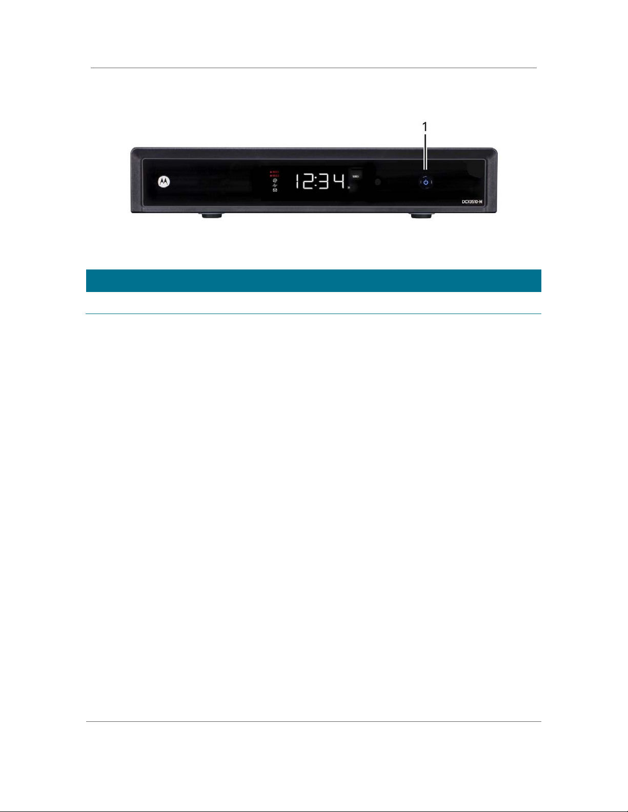
Front Panel
Figure 1: Front Panel
Item Description
1 Power — Turns the set-top on and off (standby)
DCX with OCAP Software DCX3510-M • User Guide 2
365-095-17068-x.1
Page 12
Introduction B
4
Audio Out — Analog L/R (Fixed) audio (SDTV)
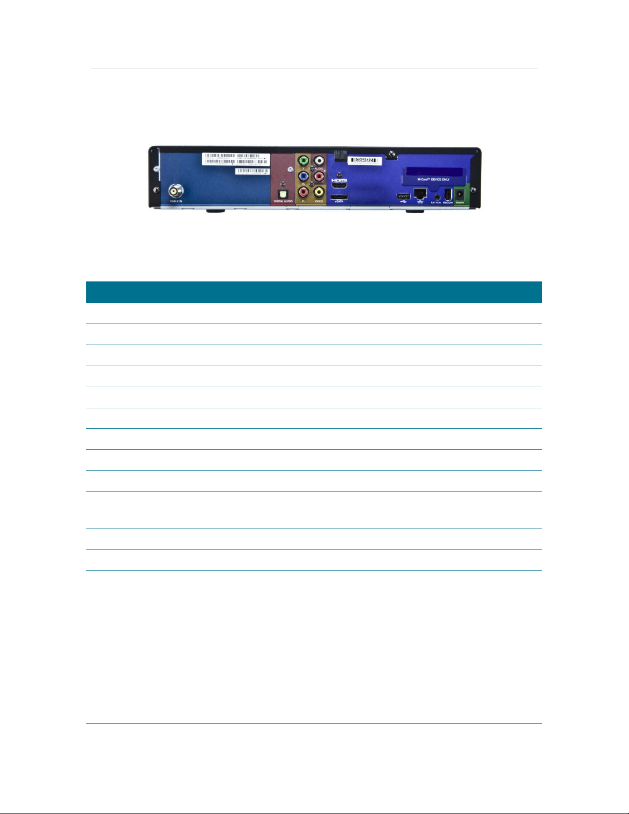
Rear Panel
Figure 2: Rear Panel
Item Description
1 Cable In — Connects to cable signal from your service provider
2 Digital Audio (Optical S/PDIF) — Provides Dolby® Digital or PCM output
3 YPbPr — Component video output (HDTV)Audio Out — Analog L/R (Variable) audio (SDTV)
5 HDMI — High-Definition TV (HDTV) connector M-Card — Inserted M-Card
6 Video Out — Composite Video (SDTV)
7 eSATA* — External Serial Advanced Technology Attachment disk interface
8 USB 2.0* — High-Speed peripheral device connection
9 Ethernet* — Network connection
10 External IR Input* — Connects to a remote control set-top accessory cable
Data test connector (service personnel only)
11 IEEE-1394 — Audio and video device connection
12 Power connector
* Availability of certain features is dependent upon application support.
DCX with OCAP Software DCX3510-M • User Guide 3
365-095-17068-x.1
Page 13

Operation B
Operation
2
Turning Power on and Off
Press POWER on the front panel or remote control to turn the DCX set-top on or off
(standby). When using the remote control, be sure it is in cable mode by pressing CABLE
before pressing POWER.
Changing Channels
You can change channels in three ways:
• Press CHANNEL + or – on the remote control to step through the channel selection.
• Enter the number of the channel you wish to view using the number keys on the
remote control.
• Select the channel in the Interactive Program Guide.
Adjusting the Volume
Press VOLUME + or – on the remote control to adjust the volume. When you adjust the
volume, the volume scale is displayed on the screen. Press MUTE on the remote control
to toggle the sound on and off.
For best audio quality when using the analog L/R (variable) volume controlled audio
outputs, use the remote control to set the DCX set-top to approximately three quarters
of the maximum volume level and then adjust the audio levels on external devices such
as your TV or A/V receiver.
When using the analog L/R (fixed) audio outputs or any of the digital audio outputs
(HDMI, IEEE-1394, or optical digital audio) adjust the audio levels on your external device
such as your TV or A/V receiver. You may also be able to program your remote to control
the volume of your TV or A/V receiver directly (refer to the remote control instruction
manual).
Interactive Program Guide
The Interactive Program Guide (IPG) displays information about TV programs and enables
you to access features such as Parental Control or Pay-Per-View. Interactive program
guides can vary with each cable service provider. Refer to the Interactive Program
Guide’s instruction manual for detailed instructions.
DCX with OCAP Software DCX3510-M • User Guide 4
365-095-17068-x.1
Page 14

Operation B
Video Format Indicators (Front Panel Display)
The front panel display of the DCX3510-M set-top is equipped with indicators to the right
side of the display that are used to indicate the currently-selected video output format on
the component video (YPbPr) and HDMI outputs. The DCX3510-M set-top is capable of
providing the following video formats on the YPbPr and HDMI video outputs:
• High Definition 1080i (1920 x 1080 pixels)
• High Definition 720p (1280 x 720 pixels)
• Enhanced Definition 480p (720 x 480 pixels)
• Standard Definition 480i (720 x 480 pixels)
The DCX3510-M set-top is also capable of passing through High-Definition 1080p
24/30/60 (1920 x 1080 pixels) source content over the HDMI video output.
Note: Availability of certain features is dependent on application support.
M-Card™
The M-Card is required to view cable television programs, previously recorded programs
on the DVR, or interactive on-demand programs. The M-Card should not be removed.
DCX with OCAP Software DCX3510-M • User Guide 5
365-095-17068-x.1
Page 15

Digital Video Recorder (DVR) B
Digital Video Recorder (DVR)
3
The DCX3510-M set-top is equipped with an internal hard drive for DVR (Digital Video
Recorder) functionality, which provides the ability to record both Standard-Definition TV
(SDTV) and High-Definition TV (HDTV) programs. Storage time varies based on the video
format and specific channel.
DVR offers the ability to control your viewing experience by pausing (time shifting) live
TV and providing trick playback modes (pause, fast forward, slow forward, fast rewind,
slow rewind). You may experience a slight delay when switching between time-shifted
and live TV.
The DCX3510-M model also includes integrated MoCA™ networking which supports
whole-home DVR capabilities. This feature extends the DVR experience to DCX3200-M
or other compatible non-DVR set-tops with integrated MoCA, when enabled by
application software. On your non-DVR set-top you can now view your DVR recordings,
playback content, and set future recordings from another room in your home.
With the DCX3510-M set-top, you can:
• Record Programming. The DCX3510-M is equipped with a 500 GB storage drive
which can record 160-300 hours of standard-definition programming, or 40 to 60
hours of high-definition programming. These capacities are based on recording digital
MPEG-2 video. A recording of a video program that is broadcast in digital MPEG-4
format requires approximately half the disk space.
• Maintain a Personal Program Library. Use the Interactive Program Guide (IPG) to
access your library.
• Control Live TV. Pause, rewind, replay and fast forward live TV.
• Simultaneously Watch Two Programs. Watch two programs and easily switch
between them using the swap key on your remote control (Dependent upon
program guide support and provided remote control).
• Simultaneous Watch and Record. Record one program in the background while
viewing another live broadcast at the same time.
• Simultaneously Record Two Shows. Record two programs from two different
channels at the same time.
• Simultaneously Record Two Shows and Watch a Recorded Program. Watch a
program recorded on your DVR while recording up to two other programs at the
same time. You can also easily switch from viewing the prerecorded program to
either of the programs you’re recording.
• Play Recorded Programming On Networked Set-tops In Your Home. Using
integrated MoCA networking, DCX3510-M recorded entertainment can be accessed
by other compatible non-DVR set-tops with integrated MoCA, when enabled by
application software.
DCX with OCAP Software DCX3510-M • User Guide 6
365-095-17068-x.1
Page 16

Digital Video Recorder (DVR) B
Using the External DVR Expansion Feature
To use the external DVR expansion feature of the DCX3510-M, first ensure that your
service provider has authorized your DCX3510-M for external DVR functionality. If
authorized, follow these steps to begin using the external DVR feature:
1. Power on your DCX3510-M and your television and ensure that you have a picture.
2. Connect a compatible eSATA hard disk drive to the DCX3510-M using the eSATA
cable supplied with your external drive enclosure. The DCX3510-M will automatically
detect that a hard disk drive has been connected to the eSATA interface.
3. The DCX3510-M displays an alert that an external hard disk drive has been
connected and that it must be formatted. Use the remote control to confirm the
format (formatting a drive erases any and all content that on the drive).
4. The DCX3510-M displays a message when formatting is complete and if the
operation succeeded or failed.
During formatting of the external hard disk drive, the DCX3510-M performs several tests
to determine if the hard drive’s performance is acceptable for DVR functionality. If the
hard drive is unable to pass these performance tests, the DCX3510-M alerts you that the
external drive is not compatible for DVR use.
5. The DCX3510-M confirms that an external drive is connected and available for use.
While using the external DVR expansion feature of your DCX3510-M:
• Recordings made on the external hard disk drive can only be played back on the
same DCX3510-M used to record the programs. You cannot connect your external
hard disk drive to another DCX3510-M (or another cable box with an eSATA
interface) and watch programs that have been recorded on the hard drive.
• You can use multiple external hard disk drives with the same DCX3510-M, however;
you can only watch the recordings that are available on the drive connected to the
DCX3510-M at that time. To watch recordings that you made on another external
drive, simply disconnect the external drive, follow the on-screen prompts, reconnect
the other external drive, and again follow the on-screen prompts.
• Whenever the DCX3510-M reboots, a temporary loss of the program listings in the
interactive program guide (IPG) is possible.
DCX with OCAP Software DCX3510-M • User Guide 7
365-095-17068-x.1
Page 17

Connecting Your DCX Set-top B
Connecting Your DCX Set-top
4
Instructions and diagrams are included for the following connections:
• High-Definition Television (HDTV)
• A/V receiver — Audio
• Standard-Definition TV (SDTV)
• Standard-Definition TV (SDTV) and VCR/DVD Recorder
• A/V receiver, Standard-Definition TV (SDTV), and VCR/DVD Recorder
Before you move or change components on your entertainment system, review the
following:
• For basic cable connections, use 75 ohm coaxial cables equipped with F-type
connectors
• Disconnect power from your equipment before connecting or changing cable
connections
For information on connecting to an HDTV, see Video Connection Options.
Caution: Do not place anything on top of your DCX set-top, especially other home
entertainment components. Be sure to provide adequate ventilation to prevent
overheating.
Video Connection Options
The DCX set-top offers several different video connection options. Component video,
HDMI, and IEEE-1394 allow you to view both High-Definition and Standard-Definition TV
programming. Composite video connections allow you to view only Standard-Definition
TV programming. HD programming will be down-converted to SD format for SD outputs.
To determine whether your TV features component video, HDMI, IEEE-1394, or
composite video, check the manual supplied with your TV.
Use the guidelines below to determine the best video connection for your home
entertainment system.
Note: Only one video connection to the TV is required. HD video can only be viewed with
HDMI, IEEE-1394, or component video connections.
DCX with OCAP Software DCX3510-M • User Guide 8
365-095-17068-x.1
Page 18

Connecting Your DCX Set-top B
HDMI or IEEE-1394 — HDTV and SDTV
HDMI and IEEE-1394 offer higher quality HD video than component video.
• If your TV has an HDMI input, this is for both audio and video. Connect a Standard
HDMI cable to the TV and to the HDMI connector on your DCX set-top.
• HDMI and IEEE-1394 outputs provide video and audio, so no separate audio
connections are required if you plan to use your TV’s speakers as the primary audio
source.
• On-screen graphics will not be displayed when you are using the IEEE-1394
connection on the rear panel of the DCX set-top. Refer to the On-Screen Graphics
section for more information.
• If your TV has a DVI input, connect a HDMI-to-DVI adapter or cable to the HDMI out
connector on the DCX set-top and the DVI HDTV connector on your TV.
Note: DVI does not provide audio. A separate audio connection must be made.
Component Video (YPbPr) — HDTV and SDTV
The YPbPr connectors on your DCX set-top provide HDTV and SDTV component video.
Note: Component video does not provide audio. A separate audio connection must be
made.
Composite Video — SDTV
Use the composite video connection to connect an SDTV.
Note: Composite video does not provide audio. A separate audio connection must be
made.
DCX with OCAP Software DCX3510-M • User Guide 9
365-095-17068-x.1
Page 19

Connecting Your DCX Set-top B
Connecting an HDTV — Single Connection for Video/Audio
Cable In
Connect an RF coaxial cable to the cable wall outlet and the CABLE IN connector on the
DCX set-top.
HDMI
If your TV has an HDMI input, this is for both audio and video if you are using the TV
speakers. Connect a Standard HDMI cable to the TV and to the HDMI connector on your
DCX set-top.
IEEE-1394
If your HDTV has an IEEE-1394 connector, you can use the IEEE-1394 for both your
video and audio connection. Connect an IEEE-1394 cable to the IEEE-1394 connector on
your HDTV and DCX set-top.
Note: On-screen graphics will not be displayed when you are using the IEEE-1394
connection on the rear panel of the DCX set-top. Refer to On-Screen Graphics for more
information.
If you have an audio/video receiver and are not using your TV’s speakers, go to
Connecting an A/V Receiver — Audio.
DCX with OCAP Software DCX3510-M • User Guide 10
365-095-17068-x.1
Page 20

Connecting Your DCX Set-top B
Figure 3: Connecting an HDTV — Single Connection for Video/Audio
Note: Only one HDTV video connection needs to be made to an HDTV.
Note: On-screen graphics will not be displayed when using IEEE-1394 connection. Refer
to On-Screen Graphics for more information.
Note: Solid lines indicate optimum connections.
Note: Optional HDMI connection to A/V Receiver shown but not required.
DCX with OCAP Software DCX3510-M • User Guide 11
365-095-17068-x.1
Page 21

Connecting Your DCX Set-top B
Connecting an HDTV — Separate Video/Audio Connections
Cable In
Connect an RF coaxial cable to the cable wall outlet and the CABLE IN connector on the
DCX set-top.
DVI
If your TV has a DVI input, use the DVI connection for your video, connect a HDMI-to-DVI
adapter or cable to the HDMI out connector on the DCX set-top and the DVI-HDTV
connector on your TV.
Note: A DVI connection supports only the video connection between the DCX set-top
and the HDTV.
To connect your audio connections with your TV speakers, go to the Audio section.
To connect your audio connections for an A/V receiver, go to Connecting an A/V Receiver
— Audio.
Component Video (YPbPr)
Connect the component video cables to the Y, Pb, and Pr connectors on your HDTV and
DCX set-top.
Note: This connection supports only the high definition video connection between the
DCX set-top and the HDTV.
Note: Be sure to match up each signal to the same connection on the TV, otherwise the
colors will not appear correctly on your TV.
To connect your audio connections with your TV speakers, go to the Audio section
below.
To connect your audio connections for an A/V receiver, go to Connecting to an A/V
Receiver — Audio.
Audio
If your TV does not have digital audio inputs, connect the stereo audio cable to the audio
L/R connectors on the DCX3510-M set-top and the Audio L/R connectors on the HDTV.
If your TV supports a digital audio inputs, use the digital audio optical S/PDIF outputs
instead of the audio L/R outputs. S/PDIF offers better audio quality, including support for
®
Dolby
Digital audio.
For information on configuring your DCX set-top settings, go to Configuring the User
Settings.
DCX with OCAP Software DCX3510-M • User Guide 12
365-095-17068-x.1
Page 22

Connecting Your DCX Set-top B
Figure 4: Connecting an HDTV — Separate Video/Audio Connections
Note: Only one video connection and one audio connection need to be made to an
HDTV.
Note: HDMI-to-DVI adapter is not included with the set-top.
Note: Solid lines indicate optimum connections.
DCX with OCAP Software DCX3510-M • User Guide 13
365-095-17068-x.1
Page 23

Connecting Your DCX Set-top B
Connecting an A/V Receiver — Audio
There are several options available for audio connections to your A/V receiver:
• Digital audio (OPTICAL S/PDIF)
• Stereo audio (AUDIO L/R)
If your A/V receiver supports it,, the optical (S/PDIF) digital audio outputs may be used in
place of the stereo audio outputs (audio L/R). These outputs offer a higher level of audio
quality, including support for Dolby Digital audio.
• Digital audio optical (S/PDIF)—Connect the optical cable to the digital audio
OPTICAL connector on the DCX set-top and the optical connector on the A/V
receiver.
• Stereo audio—Connect the stereo audio cable to the audio L/R connectors on the
DCX set-top and the audio L/R connectors on the A/V receiver.
For information on configuring your DCX set-top settings, see Configuring the User
Settings.
DCX with OCAP Software DCX3510-M • User Guide 14
365-095-17068-x.1
Page 24

Connecting Your DCX Set-top B
Figure 5: Connecting an A/V Receiver — Audio
Note: Only one audio connection needs to be made to an HDTV.
Note: Solid lines indicate optimum connections.
DCX with OCAP Software DCX3510-M • User Guide 15
365-095-17068-x.1
Page 25

Connecting Your DCX Set-top B
Connecting an SDTV
1. Connect the stereo audio cable to the AUDIO OUT L/R connectors on the DCX set-
top and the audio L/R connectors on the Standard-Definition TV (SDTV).
2. Connect a Video Composite cable to the Video Composite connector on the DCX
set-top and the input Video Composite on the TV.
These video connection methods do not support HD video. If you have an HDTV, see
Connecting an HDTV — Single Connection for Video/Audio.
Figure 6: Connecting an SDTV
Note: Composite video requires separate audio connections.
Note: Only one video connection and one audio connection are required.
Note: Solid lines indicate optimum connections.
DCX with OCAP Software DCX3510-M • User Guide 16
365-095-17068-x.1
Page 26

Connecting Your DCX Set-top B
Connecting a Standard-Definition TV (SDTV) and VCR/DVD Recorder
1. Connect a stereo audio cable to the AUDIO OUT L and R connectors on the
DCX3510-M Series set-top and the INPUT AUDIO L
VCR/DVD Recorder.
2. Connect a video cable to the VIDEO OUT connector on the DCX3510-M Series set-
top and the INPUT VIDEO connector on the VCR/DVD Recorder.
3. Connect a stereo audio cable to the OUTPUT AUDIO L and R connectors on the
VCR/DVD Recorder and the INPUT AUDIO L and R connectors on the SDTV.
4. Connect a video cable to the OUTPUT VIDEO connector on the VCR/DVD Recorder
and the INPUT VIDEO connector on the SDTV.
Note: You can also connect the TV to the VCR/DVD using the S-Video connectors, if
supported by the VCR/DVD Recorder.
Note: These video connection methods do not support HD video. If there is an HDTV,
seeConnecting an HDTV — Single Connection for Video/Audio.
and R connectors on the
DCX with OCAP Software DCX3510-M • User Guide 17
365-095-17068-x.1
Page 27

Connecting Your DCX Set-top B
Figure 7: Connecting a Standard-Definition TV (SDTV) and VCR/DVD Recorder
DCX with OCAP Software DCX3510-M • User Guide 18
365-095-17068-x.1
Page 28

Connecting Your DCX Set-top B
Connecting an A/V Receiver, SDTV, and VCR/DVD Recorder
1. Connect a stereo audio cable to the AUDIO OUT L/R connectors on the DCX set-top
and the input L/R connectors on the A/V receiver.
2. Connect a Video Composite cable to the Video Composite connector on the DCX
set-top and the Video Composite connector on the A/V receiver.
3. Connect a stereo audio cable to the VCR AUDIO OUT L/R connectors on the A/V
receiver and the INPUT AUDIO L/R connectors on the stereo VCR.
4. Connect a stereo audio cable to the output AUDIO OUT L/R connectors on the
stereo VCR and the VCR audio in L/R connectors on the A/V receiver.
5. Connect a composite video cable to the input video connector on the stereo VCR
and the video VCR OUT connector on the A/V receiver.
6. Connect a composite video cable to the output video connector on the stereo VCR
and the video VCR IN connector on the A/V receiver.
7. Connect a Composite Video cable to the input Composite Video connector on the
Standard-Definition TV (SDTV) and the TV/monitor output Composite Video
connector on the A/V receiver.
Note: The digital audio optical (optical S/PDIF) audio outputs may be used in place of the
stereo audio outputs (audio L/R). Optial S/PDIF offers a higher level of audio quality,
including support for Dolby Digital audio.
These video connection methods do not support HD video. If you have an HDTV, see
Connecting an HDTV — Single Connection for Video/Audio.
DCX with OCAP Software DCX3510-M • User Guide 19
365-095-17068-x.1
Page 29

Connecting Your DCX Set-top B
Figure 8: Connecting an A/V Receiver, SDTV, and VCR/DVD Recorder
Note: Solid lines indicate optimum connections.
Note: Consult your A/V receiver manual for additional wiring options or constraints when
including a VCR/DVD Recorder in your configuration.
DCX with OCAP Software DCX3510-M • User Guide 20
365-095-17068-x.1
Page 30

Connecting Your DCX Set-top B
Connecting Your Set-top to an External eSATA DVR
1. Contact your cable service provider to verify the set-top software necessary to
support External DVR Storage is available in your area.
2. Connect the AC power cord to the external drive and plug the external drive’s AC
power adapter into an electrical outlet.
3. Allow approximately 15 to 30 seconds for the external drive to reach operating
speed.
4. Connect one end of the eSATA cable to the set-top.
5. Connect the other end of the eSATA cable to the external drive.
6. Follow the on-screen instructions.
Note: Only connect external hard drives that have been approved by Motorola for
external DVR service. Connecting an external drive that has not been approved could
result in poor DVR performance.
Figure 9: Connecting Your Set-top to an External eSATA DVR
DCX with OCAP Software DCX3510-M • User Guide 21
365-095-17068-x.1
Page 31

Connecting Your DCX Set-top B
Data Devices
Figure 10: Data Device Connections
Do not attempt to connect data devices without contacting your service provider.
Advanced data features require the proper application and network infrastructure
to operate.
Data Features
In addition to high-quality audio and video, the DCX set-top has the capability to deliver
high-speed data services such as Internet access, e-mail, IP telephony, e-commerce, and
home banking.
Note: Your DCX set-top may be equipped with the interface connections illustrated, but
their functionality depends on the services offered by your service provider.
DCX with OCAP Software DCX3510-M • User Guide 22
365-095-17068-x.1
Page 32

Connecting Your DCX Set-top B
On-Screen Graphics
Your DCX set-top can generate graphics that overlay the video programming or fill the
entire television screen. Common examples include on-screen menus (such as the User
Setting menu), closed captions, and interactive program guides. The DCX set-top
overlays these graphics whenever you open a menu, enable closed captions, or scroll
through a program grid.
• On-screen graphics are not available on all video output combinations.
• On-screen graphics will not be displayed when you are using the IEEE-1394
connection on the rear panel of the DCX set-top.
DCX with OCAP Software DCX3510-M • User Guide 23
365-095-17068-x.1
Page 33

Recording Your Connections B
Recording Your Connections
5
Use this diagram to record connections between your home entertainment components.
You can use this diagram to reconnect your system if you move the equipment or add
new equipment.
Disconnect the power from the DCX set-top before connecting or changing cable
connections. Do not place another component or object on top of the DCX set-top.
DCX with OCAP Software DCX3510-M • User Guide 24
365-095-17068-x.1
Page 34

Configuring the User Settings B
Configuring the User Settings
6
The following describes how to configure the audio (for HDMI connections) and SD and
HD video settings for the DCX3510-M.
Note: Additional user settings are configured through the Interactive Program Guide and
not directly through the Settings Menu.
Before you adjust the output settings:
• Connect the DCX3510-M to other home entertainment devices.
• Plug the DCX3510-M into an AC power outlet.
• Turn the TV on.
When using an HDMI connection between the DCX3510-M and the television, be sure
to have the cable connected and the TV powered on before adjusting the video settings.
To optimize the output settings:
1. Ensure the DCX3510-M is installed properly.
2. With the set-top in stand-by mode, press the MENU key on the remote control.
3. If the TV is on, the on-screen User Settings menu lists the DCX3510-M settings that
can be adjusted.
4. Use the remote control to navigate the on-screen menus:
• Press the ▲ and ▼ keys to highlight the setting you wish to change.
• Press the ► key to select an option.
• To exit the setting and move to another setting, press the ▲ or ▼ key.
• To exit the menu and save your settings, press the B key on the remote control.
DCX with OCAP Software DCX3510-M • User Guide 25
365-095-17068-x.1
Page 35

Configuring the User Settings B
Figure 11: Settings Menu
Figure 12: Power ON Timer Menu
Figure 13: Power OFF Timer Menu
DCX with OCAP Software DCX3510-M • User Guide 26
365-095-17068-x.1
Page 36

Configuring the User Settings B
Video Sharpness
Adjusts the picture sharpness when viewing a standard-definition (SD) program.
Table 1: User Settings Menu Fields
Setting Description
Audio Coding
Format
Audio Output
Range
Audio Output
Selects the audio coding format on the digital output (HDMI and SPDIF) when
tuned to a channel carrying compressed audio. The following formats are
supported:
• PCM/Stereo – Send decoded audio in PCM format over the digital outputs.
• Dolby Digital – Send Dolby Digital audio over the digital outputs.
• HDMI – Send appropriate audio format, as per auto negotiation between STB and
TV, when connected over HDMI. If the negotiation indicates:
o PCM – send decoded audio in PCM format over the digital outputs
o Dolby Digital – send Dolby Digital audio over the digital outputs
• Dolby Digital Plus – send Dolby Digital Plus over HDMI and Dolby Digital over
SPDIF.
Sets the preferred audio dynamic range when the input audio is decoded by the
STB. Three options are allowed
• Narrow (default) – Enables minimum dynamic range and is most appropriate
when the TV is connected to the STB over the RF output.
• Normal – Enables moderate dynamic range which is most appropriate when a
receiver is connected to the STB over baseband or digital outputs.
• Wide – Enables the complete dynamic range to be reproduced on all outputs,
which is most suitable for advanced users who have high quality speakers and
audio equipment.
Sets the audio output to a fixed or variable setting. The fixed setting produces a
constant output level from the set-top (recommended when connected to an
external receiver). This setting does not apply to the Audio Out (Fixed) connector.
3D Mode
RF Output Channel
Power ON Timer
Status
Selections are Enabled or Disabled.
Enabled – The “D” key on the remote toggles 3D graphics display modes through
the settings, 2D, 3DTB, and 3DSS.
Disabled – The “D” key on the remote is disabled. The 3D graphics display mode is
set by the signal of the selected program.
The Video Sharpness setting affects all of the video outputs. By default, the
sharpness level of 3 is selected. The DCX3510-M supports five distinct levels of
video picture sharpness. A value of 1 corresponds to a "softer" picture while a value
of 5 corresponds to a "sharper" picture. The best sharpness setting depends upon
the video connection being used, the display quality of the TV, and personal
preference.
The default selection is channel 3.
The designated time for the set-top to power on.
This selection disables or enables the Power ON Timer.
DCX with OCAP Software DCX3510-M • User Guide 27
365-095-17068-x.1
Page 37

Configuring the User Settings B
Setting
Description
Day Option
When enabled, this selection indicates when the Power ON Timer is active.
Choices are Weekends, Weekdays, Every Sunday, Every Monday, Every Tuesday,
Every Wednesday, Every Thursday, Every Friday, or Every Saturday
Set Time
Power OFF Timer
Status This selection disables or enables the Power OFF Timer.
Day Option When enabled, this selection indicates when the Power OFF Timer is active.
Set Time
Sleep Timer
• 12-hour clock
• AM/PM
The designated time for the set-top to power off.
Choices are Weekends, Weekdays, Every Sunday, Every Monday, Every Tuesday,
Every Wednesday, Every Thursday, Every Friday, or Every Saturday
• 12 hour clock
• AM/PM
Off/On
DCX with OCAP Software DCX3510-M • User Guide 28
365-095-17068-x.1
Page 38

Troubleshooting B
Troubleshooting
7
Before calling your service provider, review this troubleshooting guide. This information
can help you quickly solve a problem. If your problem still exists, contact your service
provider.
Problem Possible Solution
The DCX set-top will
not power on
The remote control
does not work
There is no audio when
viewing cable channels
• The DCX set-top may have received a software update and may not power
on while the new software is being installed. Try again in a few minutes.
• Verify that the AC power cord is connected to the DCX set-top and an AC
outlet. Unplug the DCX set-top from the AC outlet, plug it back in, and then
press the POWER button.
• If the DCX set-top is connected to a switched outlet on another unit, verify
that the unit is powered on. Unplug the power cord from the DCX set-top’s
AC outlet, plug it back in, and then press the POWER button. It is
recommended to use an unswitched outlet, if possible.
• Press the POWER button on the DCX set-top front panel instead of the
remote control. The batteries in the remote control may be depleted.
• Verify that the remote control is in “Cable” mode.
• Verify that the remote is programmed for Motorola remote codes.
• Verify that there are no obstructions between the remote control and the
DCX set-top. Aim the remote control directly at the DCX set-top front panel,
not the TV or VCR.
• The angle between the remote control and the DCX set-top may be too
large. Stand in front of the DCX set-top and not too far to either side.
• Press and release operation keys one at a time, firmly and deliberately.
• Check the batteries in the remote control. Install new batteries if needed.
• Verify that the mute button set-top or the remote control has not been
pressed. Press MUTE on the remote control to restore sound.
• If the DCX set-top audio output is connected to the TV, verify that the MUTE
button on the TV has not been pressed.
• If the DCX set-top audio output is connected to a home theater receiver,
verify that the receiver is set to the appropriate input source and the MUTE
button on the receiver has not been pressed.
• Verify that you have the correct cables for the audio connections.
• Verify that the audio cables are firmly connected between the DCX set-top
and the audio playback device (TV, receiver, DVD player, etc.).
DCX with OCAP Software DCX3510-M • User Guide 29
365-095-17068-x.1
Page 39

Troubleshooting B
Problem
Possible Solution
There is no audio from
the center and/or
surround speakers of a
home theater receiver
connected to the DCX
set-top
There is no video on
the TV screen
• Not all programs feature full Dolby Digital [5.1] or Dolby Digital Plus [7.1]
surround sound. In some cases, the programs may only contain left and right
stereo audio.
• Verify that the HDMI or optical S/PDIF cable is firmly connected to the DCX
set-top and the home theater receiver.
• Verify that the home theater receiver is set to a surround sound audio mode
(Dolby Pro Logic®, Dolby Pro Logic II®, Dolby Pro Logic IIx®).
• Verify that the receiver is properly configured to work with all connected
speakers.
• Verify that the TV is powered on and set to the appropriate input source for
the DCX set-top.
• Verify that the DCX set-top is powered on and tuned to an authorized cable
channel.
• Verify that all video cables between the DCX set-top and the TV are firmly
connected.
• Verify that the coaxial cable feed is firmly connected to the DCX set-top and
the wall jack.
• If the DCX set-top video output is connected to a home theater unit, verify
that the home theater unit is powered on and set to the appropriate input
source.
• If the DCX set-top video output is connected to a TV through an HDMI
connection, power off the TV and then power off the DCX set-top. Wait one
second and then power on the devices.
Not all HDTVs can display every output format (1080i, 720p, 480p, or 480i)
available on the DCX set-top. Refer to your TV manufacturer’s documentation
to determine the compatible format for your TV and set the corresponding
output format for the set-top on the IPG.
No graphics or
program guides appear
on the TV screen
No closed captions
display
There are black bars to
the right and left of the
picture
If you use the IEEE-1394 connection, on-screen graphics, including closed
captions and program guides, are not displayed by the DCX set-top. On-screen
graphics and captions may still be overlaid by your TV, if enabled. Use HDMI or
component video instead of IEEE-1394.
• Verify that closed captions are enabled using the IPG menu.
• If you are using the RF out connector, verify that closed captions are enabled
on the TV.
Note: Closed captioning may not be available on the current program.
Wide screen TVs display 4:3 programs in this format unless set to Stretch.
Many HD programs are broadcast in pillar box format with black bars to the left
and right of the picture. These programs are broadcast in 16:9 HD formats even
though the video is not 16:9.
DCX with OCAP Software DCX3510-M • User Guide 30
365-095-17068-x.1
Page 40

Troubleshooting B
Problem
Possible Solution
All 4:3 HDTVs display HD programs in letterbox format (black bars above and
There are black bars on
This may occur on a 16:9 TV if the active video for an SD broadcast is in
There are black bars
above and below the
picture
below the picture) because of the shape of the display screen.
Some SD programs are broadcast in the letterbox format with black bars above
and below the picture. Some widescreen TVs offer a zoom feature that may be
able to remove the black bars. (See your TV manual for information about
zooming 4:3 video.)
all four sides of the
picture
Colors do not appear
correctly
letterbox format. To confirm, wait for a commercial or look for a graphic, such
as a network logo. If the commercial fills the screen from top to bottom, or the
graphic appears below the active video, the program is being letterboxed by
the broadcaster. You can minimize this by activating the zoom feature on the
TV.
A broadcaster may include black bars on either side of a wide screen
broadcast. This is called a “hybrid” aspect ratio and results in a black border
surrounding the video on a 4:3 TV. Because this is part of the broadcast, the
DCX set-top cannot correct the video. You may be able to minimize the border
using the zoom feature on the TV.
Be sure to match up each signal to the same YPbPr connection on the TV,
otherwise the colors will not appear correctly on your TV.
DCX with OCAP Software DCX3510-M • User Guide 31
365-095-17068-x.1
Page 41

Appendix A B
Appendix A
A
apache-jakarta-tomcat-5.0.2
Open Source Software Attribution
The following lists the attribution for the open source
software (OSS) used.
Open Source Software (OSS) Attribution for Project Ayer 2.6
Created by attrib.pl version 1.6 UTC 15:47:30, Fri Dec 11, 2009
Copyright (C) Motorola, 2009-2010.
Open Source Software Information
--------------------------------
For instructions on how to obtain a copy of any source code being
made publicly available by Motorola related to software used in
this Motorola product you may send your request in writing to:
Motorola, Inc.
OSS Management
2450 Walsh Avenue
Santa Clara, CA 95051
USA
The Motorola website opensource.motorola.com also contains
information regarding Motorola's use of open source. Motorola has
created the opensource.motorola.com to serve as a portal for
interaction with the software community-at-large. This document
contains additional information regarding licenses,
acknowledgments and required copyright notices for open source
packages used in this Motorola product.
### Summary Listing of OSS Component Licenses, by Family ###
apache_1.1
apache-commons-digester-1.5
apache-commons-el-1.0
apache-commons-modeler-1.1
apache-jakarta-regexp-1.3
apache-xerces-2.0.0
apache-xerces-2.0.2
apache-xerces-2.6.1
mx4j-2.0.1
apache_2.0
apache-ant-1.6.5
apache-beanutils-1.7.0
apache-commons-collections-3.1
apache-commons-logging-1.0.4
apache-tapestry-4.0.2
gwt-linux-1.4.10
log4j_1.2.15
log4jME-1_3alpha_7
spring-2.0.4
bouncyCastleLicense
crypto-1.2.7
BSD_license
netbsd-mktime-cfile
ttcp-cfile
eclipsePublicLicense_1.0
eclipseJdtCompiler_3.1.39
softwareWidgetToolkit_3.235
gnu_gpl_2.0
a60-0.17
bcmPublicCFE_1.4.0
BigDigits.2.1.0
busybox_1.9.1
busybox_20050528
dhcpcd-0.8.29
e2fsprogs_1.25
e2fsprogs_1.29
ebtables-v2.0.8-2
freetype-2.1.2
gcc-3.4.6
gdb_6.5
ipchains-1.3.9
ipmasqadm-0.4.2
libm-1.0.2a
ncurses-5.3
net-snmp-5.3.1
procps-2.0.17
sash-1.1
squid-2.5
termcap-1.3
uClibc-0.9.27
uClinux-dist-20070130
util-linux-2.12a
wget-1.7
DCX with OCAP Software DCX3510-M • User Guide 32
365-095-17068-x.1
Page 42

Appendix A B
xfsprogs-2.5.6
gnu_lgpl_2.1
glibc-2.3.6
iperfLicense
iperf-2.0.0
iperf-2.0.2
jgoodiesLooksLicense
jgoodies-looks-r2.2.0
MPEG_license
mpeg2-video-player
openssl_license
openssl-0.9.8b
perlArtisticLicense_5.0
depmod.pl_217
perl-2.0.1
perl-5.6.1
perl-5.6.2
python_2.0.1
python-2.0.1
vixieCronLicense
vixie-cron
westhawk_6.0
snmp6_0
### License Text, Copyright Notices, Etc. ###
*** apache_1.1 ***
License contents for all components under the apache_1.1 family:
/*
=======================================================
* The Apache Software License, Version 1.1
*
Copyright (c) 2000 The Apache Software Foundation. All rights
reserved. Redistribution and use in source and binary forms, with or
without modification, are permitted provided that the following
conditions are met:
Redistributions of source code must retain the above copyright
notice, this list of conditions and the following disclaimer.
Redistributions in binary form must reproduce the above copyright
notice, this list of conditions and the following disclaimer in the
documentation and/or other materials provided with the
distribution.
The end-user documentation included with the redistribution, if any,
must include the following acknowledgment: "This product includes
software developed by the Apache Software Foundation
(http://www.apache.org/)." Alternately, this acknowledgment may
appear in the software itself, if and wherever such third-party
acknowledgments normally appear.
The names "Apache" and "Apache Software Foundation" must not
be used to endorse or promote products derived from this software
without prior written permission. For written permission, please
contact apache@apache.org.
Products derived from this software may not be called "Apache",
nor may "Apache" appear in their name, without prior written
permission of the Apache Software Foundation.
THIS SOFTWARE IS PROVIDED ``AS IS'' AND ANY EXPRESSED OR
IMPLIED WARRANTIES, INCLUDING, BUT NOT LIMITED TO, THE
IMPLIED WARRANTIES OF MERCHANTABILITY AND FITNESS FOR
A PARTICULAR PURPOSE ARE DISCLAIMED. IN NO EVENT SHALL
THE APACHE SOFTWARE FOUNDATION OR ITS CONTRIBUTORS BE
LIABLE FOR ANY DIRECT, INDIRECT, INCIDENTAL, SPECIAL,
EXEMPLARY, OR CONSEQUENTIAL DAMAGES (INCLUDING, BUT
NOT LIMITED TO, PROCUREMENT OF SUBSTITUTE GOODS OR
SERVICES; LOSS OF USE, DATA, OR PROFITS; OR BUSINESS
INTERRUPTION) HOWEVER CAUSED AND ON ANY THEORY OF
LIABILITY, WHETHER IN CONTRACT, STRICT LIABILITY, OR TORT
(INCLUDING NEGLIGENCE OR OTHERWISE) ARISING IN ANY WAY
OUT OF THE USE OF THIS SOFTWARE, EVEN IF ADVISED OF THE
POSSIBILITY OF SUCH DAMAGE.
*
=======================================================
This software consists of voluntary contributions made by many
individuals on behalf of the Apache Software Foundation. For more
information on the Apache Software Foundation, please see
<http://www.apache.org/>.
Portions of this software are based upon public domain software
originally written at the National Center for Supercomputing
Applications, University of Illinois, Urbana-Champaign.
Specific attribution items for component apache-commons-digester-
1.5: Motorola includes component apache-commons-digester,
version 1.5, http://archive.apache.org/dist/commons/digester
Specific attribution items for component apache-commons-el-1.0:
Motorola includes component apache-commons-el, version 1.0,
http://commons.apache.org/el/
Specific attribution items for component apache-commons-modeler-
1.1: Motorola includes component apache-commons-modeler,
version 1.1, http://commons.apache.org/modeler/downloads.html
Specific attribution items for component apache-jakarta-regexp-1.3:
Motorola includes component apache-jakarta-regexp, version 1.3,
http://jakarta.apache.org/site/downloads/index.html
Specific attribution items for component apache-xerces-2.0.0:
Motorola includes component apache-xerces, version 2.0.0,
http://xerces.apache.org/
Specific attribution items for component apache-xerces-2.0.2:
Motorola includes component apache-xerces, version 2.0.2,
http://xerces.apache.org/
Specific attribution items for component apache-xerces-2.6.1:
Motorola includes component apache-xerces, version 2.6.1,
http://xerces.apache.org/
Specific attribution items for component mx4j-2.0.1: Motorola
includes component mx4j, version 3.0.2, http://mx4j.sourceforge.net
*** apache_2.0 ***
License contents for all components under the apache_2.0 family:
Apache License
Version 2.0, January 2004
http://www.apache.org/licenses/
TERMS AND CONDITIONS FOR USE, REPRODUCTION, AND
DISTRIBUTION
DCX with OCAP Software DCX3510-M • User Guide 33
365-095-17068-x.1
 Loading...