

Page 1

Software User Guide
o
o
n
n
Cayman® Operating System
Version 7.2
t
t
o
o
N
N
-
-
-
-
n
n
o
o
i
i
t
t
a
a
t
t
n
n
e
e
m
m
u
u
c
c
o
o
D
D
t
t
f
f
a
a
r
r
D
D
®
Cayman
3300 Series Gateways by Netopia
i
i
t
t
u
u
b
b
i
i
r
r
t
t
s
s
i
i
D
D
r
r
o
o
f
f
July 2003
Page 2

Disclaimers
Copyright © 2003 Netopia, Inc.
All rights reserved, Printed in the USA.
The information in this document is subject to change without notice. The statements, configurations, technical data, and recom-
mendations in this document are believed to be accurate and reliable, but are presented without express or implied warranty. Users
must take full responsibility for the applications of any products specified in this document.
Portions of this software are subject to the Mozilla Public License Version 1.1. Portions created by Netscape are copyright 1994-2000
Netscape Communications Corporation. You may obtain a copy of the license at http://www.mozilla.org/MPL/. Software distributed
under the License is distributed on an “as is” basis, WITHOUT WARRANTY OF ANY KIND, either express or implied. See the License
for the specific language governing rights and limitations under the License.
Portions of this software copyright 1988, 1991 by Carnegie Mellon University. All rights reserved. Permission to use, copy, modify,
and distribute this software and its documentation for any purpose and without fee is hereby granted, provided that the above copyright notice and this permission notice appear in supporting documentation, and that the name of Carnegie Mellon University not
be used in advertising or publicity pertaining to distribution of the software without specific, written prior permission.
CARNEGIE MELLON UNIVERSITY DISCLAIMS ALL WARRANTIES WITH REGARD TO THIS SOFTWARE, INCLUDING ALL IMPLIED WARRANTIES OF MERCHANTABILITY AND FITNESS. IN NO EVENT SHALL CMU BE LIABLE FOR ANY SPECIAL, INDIRECT, OR CONSEQUENTIAL DAMAGES OR ANY DAMAGES WHATSOEVER RESULTING FROM LOSS OF USE, DATA, OR PROFITS, WHETHER IN AN
ACTION OF CONTRACT, NEGLIGENCE, OR OTHER TORTIOUS ACTION, ARISING OUT OF OR IN CONNECTION WITH THE USE OR
PERFORMANCE OF THIS SOFTWARE.
The information in this document is proprietary to Netopia, Inc.
Tr ademarks
Netopia, Cayman, and “Making Broadband Work” are registered trademarks of Netopia, Inc. All rights reserved.
Ethernet is a registered trademark of Xerox Corporation. Microsoft and Windows are registered trademarks of Microsoft Corporation.
All other trademarks are the property of their respective owners. Mention of third-party products is for informational purposes only
and constitutes neither an endorsement nor a recommendation. Netopia assumes no responsibility with regard to the performance
or use of these products.
Statement of Conditions
In the interest of improving internal design, operational function, and /or reliability, Netopia, Inc. reserves the right to make changes
to the products described in this document without notice.
Netopia
, Inc. does not assume any liability that may occur due to the use or application of the product(s) or network con-
figurations described herein.
Netopia, Inc. Part Number: 6161158-00-01d5 v071403
2
Page 3

Table of Contents
Table of Contents
Disclaimers . . . . . . . . . . . . . . . . . . . . . . . . . . . . . . . . . . . . . . . . . 2
CHAPTER 1
CHAPTER 2
Introduction
. . . . . . . . . . . . . . . . . . . . . . . . . . . . . . . . . 11
About Cayman Documentation . . . . . . . . . . . . . . . . . . . . . . . . 11
Intended Audience . . . . . . . . . . . . . . . . . . . . . . . . . . . . . . . . . . 12
Documentation Conventions . . . . . . . . . . . . . . . . . . . . . . . . . . 13
General
Internal Web Interface
Command Line Interface
Text
Organization . . . . . . . . . . . . . . . . . . . . . . . . . . . . . . . . . . . . . . . 15
Overview of Major Capabilities . . . . . . . . . . . . . . . . . . . . . . . . . 16
A Word About Example Screens . . . . . . . . . . . . . . . . . . . . . . . 17
. . . . . . . . . . . . . . . . . . . . . . . . . . . . . . . . . . . . . . . . . . . . . . . . 13
. . . . . . . . . . . . . . . . . . . . . . . . . . . . . . . . . . . . . . . . . . . . . . . . . . . 14
Basic Mode Setup
Important Safety Instructions . . . . . . . . . . . . . . . . . . . . . . . . . . 20
POWER SUPPLY INSTALLATION
TELECOMMUNICATION INSTALLATION
Set up the Cayman Gateway . . . . . . . . . . . . . . . . . . . . . . . . . . 21
Configure the Cayman Gateway . . . . . . . . . . . . . . . . . . . . . . . 23
Cayman Gateway Status Indicator Lights . . . . . . . . . . . . . . . . 26
Home Page - Basic Mode . . . . . . . . . . . . . . . . . . . . . . . . . . . . 27
Manage My Account . . . . . . . . . . . . . . . . . . . . . . . . . . . . . . . . . . . . . . 29
Status Details . . . . . . . . . . . . . . . . . . . . . . . . . . . . . . . . . . . . . . . . . . . 30
Enable Remote Management . . . . . . . . . . . . . . . . . . . . . . . . . . . . . . . 31
Expert Mode . . . . . . . . . . . . . . . . . . . . . . . . . . . . . . . . . . . . . . . . . . . . 32
Update Firmware. . . . . . . . . . . . . . . . . . . . . . . . . . . . . . . . . . . . . . . . . 33
Factory Reset . . . . . . . . . . . . . . . . . . . . . . . . . . . . . . . . . . . . . . . . . . . 34
. . . . . . . . . . . . . . . . . . . . . . . . . . . . . . . . . . . . . 13
. . . . . . . . . . . . . . . . . . . . . . . . . . . . . . . . . . . 14
. . . . . . . . . . . . . . . . . . . . . . . . . . . . . 19
. . . . . . . . . . . . . . . . . . . . . . . . . . . 20
. . . . . . . . . . . . . . . . . . . . . . 20
3
Page 4

Table of Contents
CHAPTER 3
Expert Mode
Overview of Major Capabilities . . . . . . . . . . . . . . . . . . . . . . . . . 35
Wide Area Network Termination
Simplified Local Area Network Setup
Management
Security
Access the Web Interface . . . . . . . . . . . . . . . . . . . . . . . . . . . . . 47
Open the Web Connection
Home Page - Expert Mode
Home Page - Information
Toolbar . . . . . . . . . . . . . . . . . . . . . . . . . . . . . . . . . . . . . . . . . . . 51
Navigating the Web Interface . . . . . . . . . . . . . . . . . . . . . . . . . . 52
Breadcrumb Trail . . . . . . . . . . . . . . . . . . . . . . . . . . . . . . . . . . . . . . . . . 52
Restart . . . . . . . . . . . . . . . . . . . . . . . . . . . . . . . . . . . . . . . . . . . 53
Alert Symbol . . . . . . . . . . . . . . . . . . . . . . . . . . . . . . . . . . . . . . . . . . . . . 54
Help . . . . . . . . . . . . . . . . . . . . . . . . . . . . . . . . . . . . . . . . . . . . . 55
Configure . . . . . . . . . . . . . . . . . . . . . . . . . . . . . . . . . . . . . . . . . 56
Quickstart
Configure -> Quickstart. . . . . . . . . . . . . . . . . . . . . . . . . . . . . . . . . . . . . 56
LAN
Configure -> LAN . . . . . . . . . . . . . . . . . . . . . . . . . . . . . . . . . . . . . . . . . 58
. . . . . . . . . . . . . . . . . . . . . . . . . . . . . . . . . . 35
. . . . . . . . . . . . . . . . . . . . . . . . . . . . . . 36
PPPoE/PPPoA (Point-to-Point Protocol over Ethernet/ATM) . . . . 36
Instant-On PPP . . . . . . . . . . . . . . . . . . . . . . . . . . . . . . . . . . . . . . . 37
. . . . . . . . . . . . . . . . . . . . . . . . . . 38
DHCP (Dynamic Host Configuration Protocol) Server . . . . . . . . . 38
DNS Proxy . . . . . . . . . . . . . . . . . . . . . . . . . . . . . . . . . . . . . . . . . . 38
. . . . . . . . . . . . . . . . . . . . . . . . . . . . . . . . . . . . . . . . . . . . . 39
Embedded Web Server . . . . . . . . . . . . . . . . . . . . . . . . . . . . . . . . 39
Diagnostics . . . . . . . . . . . . . . . . . . . . . . . . . . . . . . . . . . . . . . . . . . 39
. . . . . . . . . . . . . . . . . . . . . . . . . . . . . . . . . . . . . . . . . . . . . . . . . 40
Remote Access Control . . . . . . . . . . . . . . . . . . . . . . . . . . . . . . . . 40
Password Protection . . . . . . . . . . . . . . . . . . . . . . . . . . . . . . . . . . . 40
Network Address Translation (NAT) . . . . . . . . . . . . . . . . . . . . . . . 40
Cayman Advanced Features for NAT . . . . . . . . . . . . . . . . . . . . . . 42
Internal Servers . . . . . . . . . . . . . . . . . . . . . . . . . . . . . . . . . . . . . . 43
Pinholes . . . . . . . . . . . . . . . . . . . . . . . . . . . . . . . . . . . . . . . . . . . . 43
Default Server . . . . . . . . . . . . . . . . . . . . . . . . . . . . . . . . . . . . . . . . 44
Combination NAT Bypass Configuration . . . . . . . . . . . . . . . . . . . 44
IP-Passthrough . . . . . . . . . . . . . . . . . . . . . . . . . . . . . . . . . . . . . . . 44
VPN IPSec Pass Through . . . . . . . . . . . . . . . . . . . . . . . . . . . . . . 44
VPN IPSec Tunnel Termination . . . . . . . . . . . . . . . . . . . . . . . . . . 46
Stateful Inspection Firewall . . . . . . . . . . . . . . . . . . . . . . . . . . . . . . 46
. . . . . . . . . . . . . . . . . . . . . . . . . . . . . . . . . . 47
. . . . . . . . . . . . . . . . . . . . . . . . . . . . . . . . . . 49
. . . . . . . . . . . . . . . . . . . . . . . . . . . . . . . . . . . 50
. . . . . . . . . . . . . . . . . . . . . . . . . . . . . . . . . . . . . . . . . . . . . . . 56
How to Use the Quickstart Page . . . . . . . . . . . . . . . . . . . . . . . . . 56
Setup Your Gateway using a PPP Connection . . . . . . . . . . . . . . 56
. . . . . . . . . . . . . . . . . . . . . . . . . . . . . . . . . . . . . . . . . . . . . . . . . . . . 58
4
Page 5

Table of Contents
About Closed System Mode........................................................ 63
WAN
. . . . . . . . . . . . . . . . . . . . . . . . . . . . . . . . . . . . . . . . . . . . . . . . . . 72
Configure -> WAN . . . . . . . . . . . . . . . . . . . . . . . . . . . . . . . . . . . . . . . . 72
Advanced. . . . . . . . . . . . . . . . . . . . . . . . . . . . . . . . . . . . . . . . . . . . . . . 76
IP Static Routes. . . . . . . . . . . . . . . . . . . . . . . . . . . . . . . . . . . . . . . . . . 76
IP Static ARP. . . . . . . . . . . . . . . . . . . . . . . . . . . . . . . . . . . . . . . . . . . . 77
Pinholes. . . . . . . . . . . . . . . . . . . . . . . . . . . . . . . . . . . . . . . . . . . . . . . . 78
Configure Specific Pinholes . . . . . . . . . . . . . . . . . . . . . . . . . . . . 78
Planning for Your Pinholes . . . . . . . . . . . . . . . . . . . . . . . . . . . . . 78
Example: A LAN Requiring Three Pinholes . . . . . . . . . . . . . . . . 78
Pinhole Configuration Procedure . . . . . . . . . . . . . . . . . . . . . . . . 81
IPMaps . . . . . . . . . . . . . . . . . . . . . . . . . . . . . . . . . . . . . . . . . . . . . . . . 85
Configure the IPMaps Feature . . . . . . . . . . . . . . . . . . . . . . . . . . . . . . 85
FAQs for the IPMaps Feature ..................................................... 85
What are IPMaps and how are they used? . . . . . . . . . . . . . . . . . 85
What types of servers are supported by IPMaps? . . . . . . . . . . . 86
Can I use IPMaps with my PPPoE or PPPoA connection? . . . . . 86
Will IPMaps allow IP addresses from different subnets to be assigned to my
Gateway? . . . . . . . . . . . . . . . . . . . . . . . . . . . . . . . . . . . . . . . . . . 86
IPMaps Block Diagram................................................................ 87
Default Server . . . . . . . . . . . . . . . . . . . . . . . . . . . . . . . . . . . . . . . . . . . 88
Configure a Default Server . . . . . . . . . . . . . . . . . . . . . . . . . . . . . 88
Typical Network Diagram . . . . . . . . . . . . . . . . . . . . . . . . . . . . . . 90
NAT Combination Application . . . . . . . . . . . . . . . . . . . . . . . . . . . 91
IP-Passthrough . . . . . . . . . . . . . . . . . . . . . . . . . . . . . . . . . . . . . . 91
A restriction . . . . . . . . . . . . . . . . . . . . . . . . . . . . . . . . . . . . . . . . . 92
DNS. . . . . . . . . . . . . . . . . . . . . . . . . . . . . . . . . . . . . . . . . . . . . . . . . . . 93
DHCP Server. . . . . . . . . . . . . . . . . . . . . . . . . . . . . . . . . . . . . . . . . . . . 93
SNMP . . . . . . . . . . . . . . . . . . . . . . . . . . . . . . . . . . . . . . . . . . . . . . . . . 94
Advanced -> Ethernet Bridge . . . . . . . . . . . . . . . . . . . . . . . . . . . . . . . 96
Configuring for Bridge Mode . . . . . . . . . . . . . . . . . . . . . . . . . . . . . . . . 97
System. . . . . . . . . . . . . . . . . . . . . . . . . . . . . . . . . . . . . . . . . . . . . . . . 100
Syslog Parameters . . . . . . . . . . . . . . . . . . . . . . . . . . . . . . . . . . . . . . 101
Internal Servers . . . . . . . . . . . . . . . . . . . . . . . . . . . . . . . . . . . . . . . . . 103
Software Hosting . . . . . . . . . . . . . . . . . . . . . . . . . . . . . . . . . . . . . . . . 104
List of Supported Games and Software ...................................... 105
Rename a User(PC) . . . . . . . . . . . . . . . . . . . . . . . . . . . . . . . . . . . . . 105
Clear Options. . . . . . . . . . . . . . . . . . . . . . . . . . . . . . . . . . . . . . . . . . . 106
Security . . . . . . . . . . . . . . . . . . . . . . . . . . . . . . . . . . . . . . . . . 108
Passwords. . . . . . . . . . . . . . . . . . . . . . . . . . . . . . . . . . . . . . . . . . . . . 109
Create and Change Passwords . . . . . . . . . . . . . . . . . . . . . . . . 109
Firewall . . . . . . . . . . . . . . . . . . . . . . . . . . . . . . . . . . . . . . . . . . . . . . . 111
Use a Cayman Firewall ............................................................... 111
BreakWater Basic Firewall . . . . . . . . . . . . . . . . . . . . . . . . . . . . 111
5
Page 6

Table of Contents
Configuring for a BreakWater Setting.......................................... 112
TIPS for making your BreakWater Basic Firewall Selection ....... 113
Basic Firewall Background .......................................................... 113
IPSec . . . . . . . . . . . . . . . . . . . . . . . . . . . . . . . . . . . . . . . . . . . . . . . . . 116
How to Configure a SafeHarbour VPN........................................ 117
VPN IPSec Tunnel at the Gateway . . . . . . . . . . . . . . . . . . . . . . 117
Parameter Description and Setup . . . . . . . . . . . . . . . . . . . . . . . 118
IPSec Tunnel Parameter Setup Worksheet . . . . . . . . . . . . . . . . 120
SafeHarbour Tunnel Setup . . . . . . . . . . . . . . . . . . . . . . . . . . . . . 120
Task 1: Ensure that you have SafeHarbour VPN enabled. ......... 121
Task2: Complete Parameter Setup Worksheet........................... 121
Task 3: Enable IPSec.................................................................. 121
Task 4: Make the IPSec Tunnel Entries ...................................... 122
Task 5: Make the Tunnel Details entries ..................................... 124
Stateful Inspection . . . . . . . . . . . . . . . . . . . . . . . . . . . . . . . . . . . . . . . 125
Stateful Inspection Firewall installation procedure . . . . . . . . . . . . . . . 125
Exposed Addresses . . . . . . . . . . . . . . . . . . . . . . . . . . . . . . . . . . . . . . 127
Stateful Inspection Options. . . . . . . . . . . . . . . . . . . . . . . . . . . . . . . . . 130
Open Ports in Default Stateful Inspection Installation . . . . . . . . . . . . 131
Log Event Dispositions . . . . . . . . . . . . . . . . . . . . . . . . . . . . . . . . . . . . 131
Security Log . . . . . . . . . . . . . . . . . . . . . . . . . . . . . . . . . . . . . . . . . . . . 132
Using the Security Monitoring Log .............................................. 133
Timestamp Background............................................................... 135
Install . . . . . . . . . . . . . . . . . . . . . . . . . . . . . . . . . . . . . . . . . . . 136
Install Software . . . . . . . . . . . . . . . . . . . . . . . . . . . . . . . . . . . . . . . . . . 137
Updating Your Gateway’s CaymanOS Version . . . . . . . . . . . . . 137
Task 1: Required Files . . . . . . . . . . . . . . . . . . . . . . . . . . . . . . . . . . . . 138
Task 2: CaymanOS Image File. . . . . . . . . . . . . . . . . . . . . . . . . . . . . . 138
Install Keys . . . . . . . . . . . . . . . . . . . . . . . . . . . . . . . . . . . . . . . . . . . . . 142
Use Cayman Software Feature Keys . . . . . . . . . . . . . . . . . . . . . . . . . 142
Obtaining Software Feature Keys .............................................. 142
Procedure - Install a New Feature Key File................................. 142
To check your installed features:................................................. 144
CHAPTER 4
6
Basic Troubleshooting
Status Indicator Lights . . . . . . . . . . . . . . . . . . . . . . . . . . . . . . 148
Factory Reset Switch . . . . . . . . . . . . . . . . . . . . . . . . . . . . . . . 155
. . . . . . . . . . . . . . . . . . . . . . . . . 147
Page 7

Table of Contents
CHAPTER 5
CHAPTER 6
Advanced Troubleshooting
Home Page
Expert Mode
System Status ............................................................................. 161
Ports: Ethernet. . . . . . . . . . . . . . . . . . . . . . . . . . . . . . . . . . . . . . . . . . 162
Ports: DSL . . . . . . . . . . . . . . . . . . . . . . . . . . . . . . . . . . . . . . . . . . . . . 163
DSL: Circuit Configuration. . . . . . . . . . . . . . . . . . . . . . . . . . . . . . . . . 164
System Log: Entire . . . . . . . . . . . . . . . . . . . . . . . . . . . . . . . . . . . . . . 165
Diagnostics.................................................................................. 166
Network Tools ............................................................................. 167
Command Line Interface
Overview . . . . . . . . . . . . . . . . . . . . . . . . . . . . . . . . . . . . . . . . 172
Starting and Ending a CLI Session . . . . . . . . . . . . . . . . . . . . 175
Logging In
Ending a CLI Session
Saving Settings
Using the CLI Help Facility . . . . . . . . . . . . . . . . . . . . . . . . . . . 176
About SHELL Commands . . . . . . . . . . . . . . . . . . . . . . . . . . . 177
SHELL Prompt
SHELL Command Shortcuts
SHELL Commands . . . . . . . . . . . . . . . . . . . . . . . . . . . . . . . . . 178
Common Commands
WAN Commands
About CONFIG Commands . . . . . . . . . . . . . . . . . . . . . . . . . . 190
CONFIG Mode Prompt
Navigating the CONFIG Hierarchy
Entering Commands in CONFIG Mode
Guidelines: CONFIG Commands
Displaying Current Gateway Settings
Step Mode: A CLI Configuration Technique
Validating Your Configuration
CONFIG Commands . . . . . . . . . . . . . . . . . . . . . . . . . . . . . . . 196
DSL Commands
ATM Settings . . . . . . . . . . . . . . . . . . . . . . . . . . . . . . . . . . . . . . . 196
Bridging Settings
Common Commands .................................................................. 198
DHCP Settings
. . . . . . . . . . . . . . . . . . . . . . . . . . . . . . . . . . . . . . . . . . . . 158
. . . . . . . . . . . . . . . . . . . . . . . . . . . . . . . . . . . . . . . . . . . 161
. . . . . . . . . . . . . . . . . . . . . . . 171
. . . . . . . . . . . . . . . . . . . . . . . . . . . . . . . . . . . . . . . . . . . . . 175
. . . . . . . . . . . . . . . . . . . . . . . . . . . . . . . . . . . . 175
. . . . . . . . . . . . . . . . . . . . . . . . . . . . . . . . . . . . . . . . . 176
. . . . . . . . . . . . . . . . . . . . . . . . . . . . . . . . . . . . . . . . . . 177
. . . . . . . . . . . . . . . . . . . . . . . . . . . . . . . . . . . . . 178
. . . . . . . . . . . . . . . . . . . . . . . . . . . . . . . . . . . . . . . . 187
. . . . . . . . . . . . . . . . . . . . . . . . . . . . . . . . . . . . . . . . 196
. . . . . . . . . . . . . . . . . . . . . . . . . . . . . . . . . . . . . . . . 198
. . . . . . . . . . . . . . . . . . . . . . . . . . . . . . . . . . . . . . . . . 199
. . . . . . . . . . . . . . . . . . . . . 157
. . . . . . . . . . . . . . . . . . . . . . . . . . . . . . . 177
. . . . . . . . . . . . . . . . . . . . . . . . . . . . . . . . . . . 190
. . . . . . . . . . . . . . . . . . . . . . . . . . 190
. . . . . . . . . . . . . . . . . . . . . . . 192
. . . . . . . . . . . . . . . . . . . . . . . . . . . 193
. . . . . . . . . . . . . . . . . . . . . . . . 194
. . . . . . . . . . . . . . . . . . . 194
. . . . . . . . . . . . . . . . . . . . . . . . . . . . . . 195
7
Page 8

Table of Contents
Common Commands................................................................... 199
DMT Settings
DSL Commands .......................................................................... 200
Domain Name System Settings
Common Commands................................................................... 201
IP Settings
Common Settings........................................................................ 202
DSL Settings................................................................................ 203
Ethernet Hub Settings ................................................................. 205
Default IP Gateway Settings........................................................ 208
IP-over-PPP Settings . . . . . . . . . . . . . . . . . . . . . . . . . . . . . . . . . 208
Static ARP Settings . . . . . . . . . . . . . . . . . . . . . . . . . . . . . . . . . . 211
IGMP Forwarding ........................................................................ 212
IPsec Passthrough ...................................................................... 212
Static Route Settings................................................................... 212
IPMaps Settings
Network Address Translation (NAT) Default Settings
Network Address Translation (NAT) Pinhole Settings
PPPoE /PPPoA Settings
Configuring Basic PPP Settings . . . . . . . . . . . . . . . . . . . . . . . . . 217
Configuring Port Authentication . . . . . . . . . . . . . . . . . . . . . . . . . 220
Ethernet Port Settings
Command Line Interface Preference Settings
Port Renumbering Settings
Security Settings
Firewall Settings (for BreakWater Firewall) ................................. 223
IPsec Settings.............................................................................. 224
SafeHarbour IPSec Settings ....................................................... 224
Internet Key Exchange (IKE) Settings......................................... 228
Stateful Inspection....................................................................... 229
Example:...................................................................................... 230
SNMP Settings
System Settings . . . . . . . . . . . . . . . . . . . . . . . . . . . . . . . . . . . . . . . . . 233
Syslog. . . . . . . . . . . . . . . . . . . . . . . . . . . . . . . . . . . . . . . . . . . . . . . . . 236
Default syslog installation procedure........................................... 237
Wireless Settings (supported models) . . . . . . . . . . . . . . . . . . . . . . . . 239
. . . . . . . . . . . . . . . . . . . . . . . . . . . . . . . . . . . . . . . . . . . 200
. . . . . . . . . . . . . . . . . . . . . . . . . . . . . 201
. . . . . . . . . . . . . . . . . . . . . . . . . . . . . . . . . . . . . . . . . . . . . 202
. . . . . . . . . . . . . . . . . . . . . . . . . . . . . . . . . . . . . . . . . 214
. . . . . . . . . . . . . 215
. . . . . . . . . . . . . 216
. . . . . . . . . . . . . . . . . . . . . . . . . . . . . . . . . . . 217
. . . . . . . . . . . . . . . . . . . . . . . . . . . . . . . . . . . . . 221
. . . . . . . . . . . . . . . . . . 221
. . . . . . . . . . . . . . . . . . . . . . . . . . . . . . . . 222
. . . . . . . . . . . . . . . . . . . . . . . . . . . . . . . . . . . . . . . . . 223
. . . . . . . . . . . . . . . . . . . . . . . . . . . . . . . . . . . . . . . . . . 232
CHAPTER 7
8
Glossary . . . . . . . . . . . . . . . . . . . . . . . . . . . . . . . . . 243
-----A----- ...................................................................................... 243
-----B----- ...................................................................................... 245
-----C----- ...................................................................................... 245
Page 9

Table of Contents
-----D-----...................................................................................... 246
-----E----- ...................................................................................... 248
-----F----- ...................................................................................... 249
-----H-----...................................................................................... 250
-----I----- ....................................................................................... 251
-----K----- ...................................................................................... 252
-----L----- ...................................................................................... 252
-----M----- ..................................................................................... 253
-----N-----...................................................................................... 254
-----P----- ...................................................................................... 255
-----R-----...................................................................................... 256
-----S----- ...................................................................................... 257
-----T----- ...................................................................................... 259
-----U-----...................................................................................... 259
-----V----- ...................................................................................... 260
-----W----- ..................................................................................... 260
CHAPTER 8
Technical Specifications and Safety Information . . . . . 261
Description . . . . . . . . . . . . . . . . . . . . . . . . . . . . . . . . . . . . . . . 261
Dimensions: . . . . . . . . . . . . . . . . . . . . . . . . . . . . . . . . . . . . . . . . 261
Communications interfaces: . . . . . . . . . . . . . . . . . . . . . . . . . . . 261
Power requirements . . . . . . . . . . . . . . . . . . . . . . . . . . . . . . . . . . . . . 262
Environment . . . . . . . . . . . . . . . . . . . . . . . . . . . . . . . . . . . . . . . . . . . 262
Operating temperature: . . . . . . . . . . . . . . . . . . . . . . . . . . . . . . . 262
Storage temperature: . . . . . . . . . . . . . . . . . . . . . . . . . . . . . . . . 262
Relative storage humidity: . . . . . . . . . . . . . . . . . . . . . . . . . . . . . 262
Software and protocols . . . . . . . . . . . . . . . . . . . . . . . . . . . . . . . . . . . 262
Software media: . . . . . . . . . . . . . . . . . . . . . . . . . . . . . . . . . . . . 262
Routing: . . . . . . . . . . . . . . . . . . . . . . . . . . . . . . . . . . . . . . . . . . . 262
WAN support: . . . . . . . . . . . . . . . . . . . . . . . . . . . . . . . . . . . . . . 262
Security: . . . . . . . . . . . . . . . . . . . . . . . . . . . . . . . . . . . . . . . . . . 262
Management/configuration methods: . . . . . . . . . . . . . . . . . . . . 262
Diagnostics: . . . . . . . . . . . . . . . . . . . . . . . . . . . . . . . . . . . . . . . . 262
Agency approvals . . . . . . . . . . . . . . . . . . . . . . . . . . . . . . . . . . 263
North America ............................................................................. 263
International................................................................................. 263
Regulatory notices. . . . . . . . . . . . . . . . . . . . . . . . . . . . . . . . . . . . . . . 263
European Community. . . . . . . . . . . . . . . . . . . . . . . . . . . . . . . . . 263
Manufacturer’s Declaration of Conformance . . . . . . . . . . . . . 264
United States . . . . . . . . . . . . . . . . . . . . . . . . . . . . . . . . . . . . . . . 264
Service requirements . . . . . . . . . . . . . . . . . . . . . . . . . . . . . . . . 265
9
Page 10

Table of Contents
Canada . . . . . . . . . . . . . . . . . . . . . . . . . . . . . . . . . . . . . . . . . . . . 265
Declaration for Canadian users................................................... 265
Caution ........................................................................................ 266
Important Safety Instructions . . . . . . . . . . . . . . . . . . . . . . . . . 267
Australian Safety Information ...................................................... 267
Caution ........................................................................................ 267
Caution ........................................................................................ 267
Telecommunication installation cautions..................................... 267
FCC Part 68 Information . . . . . . . . . . . . . . . . . . . . . . . . . . . . . 268
FCC Requirements. . . . . . . . . . . . . . . . . . . . . . . . . . . . . . . . . . . . . . . 268
FCC Statements . . . . . . . . . . . . . . . . . . . . . . . . . . . . . . . . . . . . . . . . . 268
Electrical Safety Advisory . . . . . . . . . . . . . . . . . . . . . . . . . . . . 270
Index . . . . . . . . . . . . . . . . . . . . . . . . . . . . . . . . . . . . . . . . . . . . .271
10
Page 11

About Cayman Documentation
CHAPTER 1 Introduction
About Cayman Documentation
☛ NOTE:
This guide describes the wide variety of features and functionality
of the Cayman Gateway , when used in Router mode. The Cayman
Gateway may also be delivered in Bridge mode. In Bridge mode,
the Gateway acts as a pass-through device and allows the workstations on your LAN to have public addresses directly on the
Internet.
Netopia, Inc. provides a suite of technical information for its Cayman-series
family of intelligent enterprise and consumer Gateways. It consists of:
• Software User Guide
• Dedicated Quickstart guides
11
Page 12

• Specific White Papers
The documents are available in electronic form as Portable Document Format (PDF) files. They are viewed (and printed) from Adobe Acrobat Reader,
Exchange, or any other application that supports PDF files.
They are downloadable from Netopia’s website:
http://www.netopia.com/
Intended Audience
This guide is targeted primarily to residential service subscribers.
Expert Mode sections may also be of use to the support staffs of broad-
band service providers and advanced residential service subscribers.
See “Expert Mode” on page 35.
12
Page 13

Documentation Conventions
Documentation Conventions
General
This manual uses the following conventions to present information:
Convention (Typeface) Description
bold italic
monospaced
bold italic sans serif
terminal
bold terminal
Italic
Italic type indicates the complete titles
Menu commands
Web GUI page links and button names
Computer display text
User-entered text
of manuals.
Internal Web Interface
Convention (Graphics) Description
dot-dashed rectangle or
line
solid rounded rectangle
with an arrow
Denotes an “excerpt” from a Web page
or the visual truncation of a Web page
Denotes an area of emphasis on a W eb
page
13
Page 14

Command Line Interface
Syntax conventions for the Cayman Gateway command line interface are as
follows:
Convention Description
straight ([ ]) brackets in cmd
line
curly ({ }) brackets, with values
separated with vertical bars (|).
bold terminal type
Optional command arguments
Alternative values for an argument are
presented in curly ({ }) brackets, with
values separated with vertical bars (|).
User-entered text
face
italic terminal
type face
Variables for which you supply your
own values
Text
The words “Cayman Gateway” and “Gateway” refer to the Netopia Cayman
Gateway.
The expressions “Release 7.2” and “R 7.2” refer to the most recent generally available Cayman Operating System.
14
Page 15

Organization
Organization
This guide consists of eight chapters, including a glossary, and an index. It
is organized as follows:
• Chapter 1, “Introduction” — Describes the Cayman document suite,
the purpose of, the audience for, and structure of this guide. It gives a
table of conventions and presents a product description summary.
• Chapter 2, “Basic Mode Setup” — Describes how to get up and run-
ning with your Cayman Gateway.
• Chapter 3, “Expert Mode” — Focuses on the “Expert Mode” Web-
based user interface for advanced users. It is organized in the same way
as the Web UI is organized. As you go through each section, functions
and procedures are discussed in detail.
• Chapter 4, “Basic Troubleshooting” — Gives some simple sugges-
tions for troubleshooting problems with your Gateway’s initial configuration.
• Chapter 5, “Advanced Troubleshooting” — Gives suggestions and
descriptions of expert tools to use to troubleshoot your Gateway’s configuration.
• Chapter 6, “Command Line Interface” — Describes all the current
text-based commands for both the SHELL and CONFIG modes. A summary table and individual command examples for each mode is provided.
• Chapter 7, “Glossary”
• Chapter 8, “Technical Specifications and Safety Information”
• Index
15
Page 16

Overview of Major Capabilities
The Netopia Gateway offers simplified setup and management features as
well as advanced broadband router capabilities. The following are some of
the main features of the Netopia Gateway:
• Wide Area Network Termination
The Gateway combines a DSL modem with an Internet router. It translates protocols used on the Internet to protocols used by home personal computers and
eliminates the need for special desktop software (i.e. PPPoE client).
•
Simplified Local Area Network Setup
Built-in DHCP and DNS proxy features minimize or eliminate the need to program any network configuration into your home personal computer.
• Management
A Web server built into the Cayman Operating System makes setup and maintenance easy using standard browsers. Diagnostic tools facilitate troubleshooting.
•
Security
Network Address Translation (NAT), password protection, and other built-in
security features prevent unauthorized remote access to your network. Pinholes, default server, and other features permit access to computers on your
home network that you can specify.
16
Technical details are discussed in “Expert Mode” on page 35.
Page 17

A Word About Example Screens
A Word About Example Screens
This manual contains many example screen illustrations. Since Netopia
Cayman Series Gateways offer a wide variety of features and functionality,
the example screens shown may not appear exactly the same for your particular Gateway or setup as they appear in this manual. The example
screens are for illustrative and explanatory purposes, and should not be
construed to represent your own unique environment.
17
Page 18

18
Page 19

CHAPTER 2 Basic Mode Setup
Most users will find that the basic Quickstart configuration is all that they
ever need to use. This section may be all that you ever need to configure
and use your Cayman Gateway . The following instructions cover installation
in Router Mode.
This section covers:
• “Important Safety Instructions” on page 20
• “Set up the Cayman Gateway” on page 21
• “Configure the Cayman Gateway” on page 23
• “Cayman Gateway Status Indicator Lights” on page 26
• “Home Page - Basic Mode” on page 27
19
Page 20

Important Safety Instructions
POWER SUPPLY INSTALLATION
Connect the power supply cord to the power jack on the Cayman Gateway.
Plug the power supply into an appropriate electrical outlet.
☛ CAUTION:
Depending on the power supply provided with the product, either
the direct plug-in power supply blades, power supply cord plug or
the appliance coupler serves as the mains power disconnect. It
is important that the direct plug-in power supply , socket-outlet or
appliance coupler be located so it is readily accessible.
CAUTION (North America Only): For use only with a CSA Certified or UL Listed Limited Power Source or Class 2 power supply,
rated 12Vdc, 1.5A.
(Sweden) Apparaten skall anslutas till jordat uttag när den
ansluts till ett nätverk
(Norway) Apparatet må kun tilkoples jordet stikkontakt.
USB-powered models: For Use with Listed I.T.E. Only
20
TELECOMMUNICATION INSTALLATION
When using your telephone equipment, basic safety precautions should
always be followed to reduce the risk of fire, electric shock and injury to persons, including the following:
• Do not use this product near water, for example, near a bathtub, wash
bowl, kitchen sink or laundry tub, in a wet basement or near a swimming
pool.
• Avoid using a telephone (other than a cordless type) during an electrical
storm. There may be a remote risk of electrical shock from lightning.
• Do not use the telephone to report a gas leak in the vicinity of the leak.
SA VE THESE INSTRUCTIONS
Page 21

Set up the Cayman Gateway
Set up the Cayman Gateway
Refer to your Quickstart Guide for instructions on how to connect your Cayman gateway to your power source, PC or local area network, and your Internet access point, whether it is a dedicated DSL outlet or a DSL or cable
modem. Different Cayman Gateway models are supplied for any of these
connections. Be sure to enable Dynamic Addressing on your PC. Perform
the following:
• Windows 95, 98 and ME
• Right-Click on the Network Neighborhood icon on your Windows desktop and select Properties from the pull-down menu.
• In the list of network components, highlight the entry that says
“TCP/IP ([your Ethernet card here])”.
• Click the Properties button.
• Click the Obtain an IP address automatically radio button. Click the
DNS Configuration tab. Click the Disable DNS radio button. Click the
Gateway tab and remove any installed Gateways. Click the OK button
twice. When prompted, restart your PC.
Proceed to “Configure the Cayman Gateway” on page 23.
• Windows 2000 and XP
• Right Click on the My Network Places icon on your Windows desktop
and select Properties.
• Select your Local Area Connection.
• Right click on your Local Area Connection and select Properties.
• Select Internet Protocol [TCP/IP].
• Click the Properties button.
• Click the Obtain IP address automatically radio button and the Obtain
DNS server address automatically radio button. Click the OK button.
21
Page 22

Proceed to “Configure the Cayman Gateway” on page 23.
• Macintosh Mac OS
Your Macintosh must be using MacOS 7.6.1 or higher.
• Select Control Panels from the Apple Menu.
• Open the TCP/IP Control Panel.
• Choose Connect via Ethernet.
• Choose Configure Using DHCP Server. Close and Save.
• You do not have to restart the Macintosh. Launch your Web browser,
such as Netscape Navigator or Internet Explorer.
Proceed to “Configure the Cayman Gateway” on page 23.
• Mac OS X
• Launch System Preferences from the Dock or from the Apple Menu.
• Select the Network Preference Pane.
• Choose Show: Built-in Ethernet.
• Click the TCP/IP tab.
22
• Choose Configure: Using DHCP.
• Quit System Preferences.
• You do not have to restart the Macintosh. Launch your Web browser,
such as Netscape Navigator or Internet Explorer.
Proceed to “Configure the Cayman Gateway” on page 23.
Page 23

Configure the Cayman Gateway
Configure the Cayman Gateway
1. Run your Web browser application, such as Netscape Navigator or
Microsoft Internet Explorer, from the computer connected to the Cayman
Gateway.
Enter http://192.168.1.254 in the Location text box.
The Admin Password page appears.
Access to your Cayman device can be controlled through two access control accounts, Admin or User.
• The Admin, or administrative user, performs all configuration, manage-
ment or maintenance operations on the Gateway.
• The User account provides monitor capability only.
A user may NOT change the configuration, perform upgrades or invoke
maintenance functions.
For the security of your connection, an Admin password must be set on
the Cayman unit.
23
Page 24
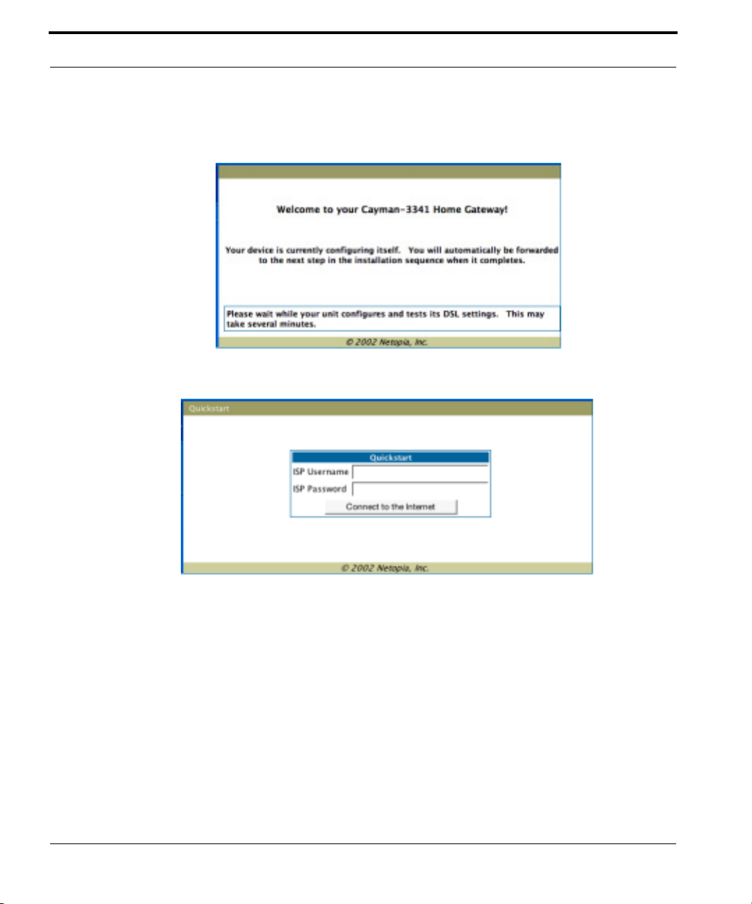
The browser then displays the Welcome page.
The browser then displays the Quickstart web page.
24
2. Enter the username and password supplied by your Internet Service Pro-
vider. Click the
Connect to the Internet
button.
Once you enter your username and password here, you will no longer
need to enter them whenever you access the Internet. The Cayman Gateway stores this information and automatically connects you to the Internet.
Page 25
Configure the Cayman Gateway
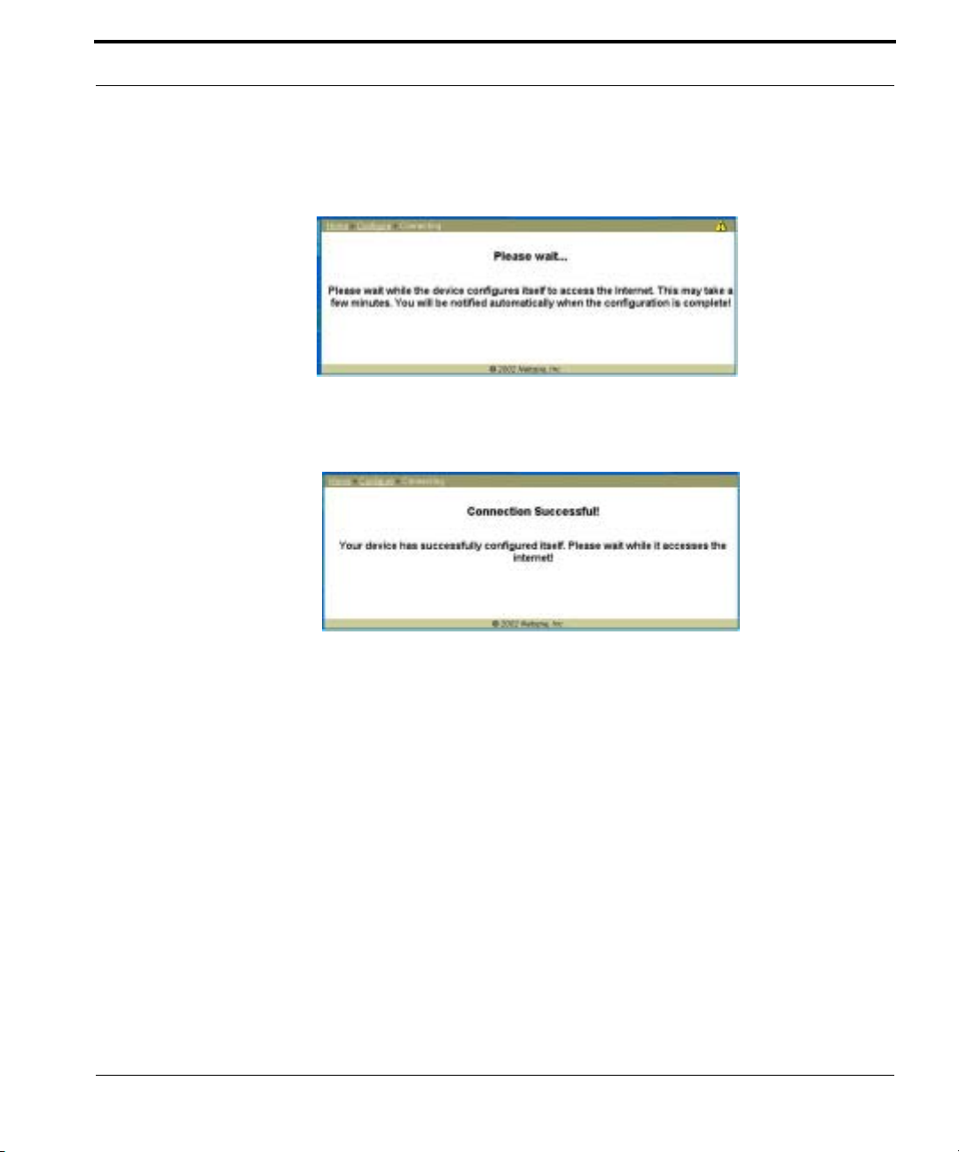
The Gateway displays a message while it configures itself.
3. When the connection succeeds, your browser will display a success
message.
Once a connection is established, your browser is redirected to your service provider’s home page or a registration page on the Internet.
4. Congratulations! Your installation is complete. You can now surf to your
favorite Web sites by typing an URL in your browser’s location box or by
selecting one of your favorite Internet bookmarks.
25
Page 26

Cayman Gateway Status Indicator Lights
Colored LEDs on your Cayman Gateway indicate the status of various port
activity . Different Gateway models have different ports for your connections
and different indicator LEDs. The Quickstart Guide accompanying your Cayman Gateway describes the behavior of the various indicator LEDs.
Example status indicator lights
Status Indicator Lights (LEDs)
netopia
26
Page 27
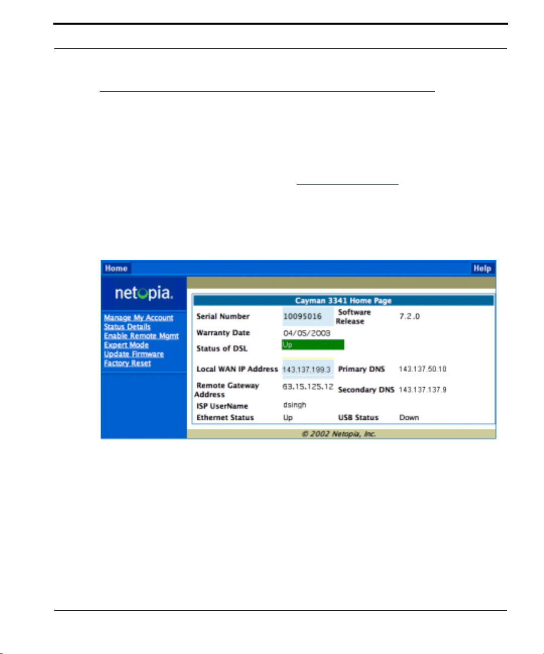
Home Page - Basic Mode
Home Page - Basic Mode
After you have performed the basic Quickstart configuration, any time you
log in to your Cayman Gateway you will access the Cayman Gateway Home
Page.
You access the Home Page by typing
browser’s location box.
The Basic Mode Home Page appears.
http://192.168.1.254
in your Web
27
Page 28

The Home Page displays the following information in the center section:
Item Description
Local WAN IP
Address
Remote
Gateway
Address
Primary DNS
Secondary
DNS
ISP Username
Status of
Connection
Serial Number
Software
Release
Warranty Date
This is the negotiated address of the Gateway’s WAN interface.
This address is usually dynamically assigned.
This is the negotiated address of the remote router to which this
Gateway is connected.
These are the negotiated DNS addresses.
This is your PPPoE username as assigned by your service provider.
‘Waiting for DSL’ is displayed while the Gateway is training. This
should change to ‘Up’ within two minutes.
‘Up’ is displayed when the ADSL line is synched and the PPPoE
session is established.
‘Down’ indicates inability to establish a connection; possible line
failure.
This is the unique serial number of your Gateway.
This is the version number of the current embedded software in
your Gateway.
This is the date that your Gateway was installed and enabled.
28
Ethernet
Local Area Network (Ethernet) is either Up or Down
Status
USB Status
If your Gateway is so equipped, Local Area Network (USB)
is either Up or Down
The links in the left-hand column on this page allow you to manage or configure several features of your Gateway. Each link is described in its own
section.
Page 29
Home Page - Basic Mode
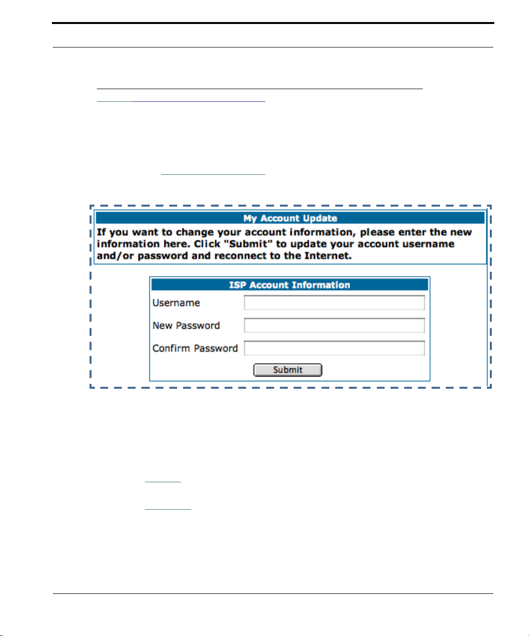
Link: Manage My Account
You can change your ISP account information for the Cayman Gateway. You
can also manage other aspects of your account on your service provider’s
account management Web site.
Click on the
Manage My Account
link. The Manage My Account page
appears.
Enter your username, and then your new password. Confirm your new password. For security, your actual passwords are not displayed on the screen
as you type. You must enter the new password twice to be sure you have
typed it correctly.
Click the
Click the
Submit
Continue
button.
button. You will be taken to your service provider’s Web
site account management page.
29
Page 30

Link: Status Details
If you need to diagnose any problems with your Cayman Gateway or its connection to the Internet, you can run a sophisticated diagnostic tool. It
checks several aspects of your physical and electronic connection and
reports its results on-screen. This can be useful for troubleshooting, or
when speaking with a technical support technician.
Click on the
Click on the
detailed description of these tests, see “Diagnostics” on page 166.
Status Details
Run Diagnostics
link. The Diagnostics page appears.
button to run your diagnostic tests. For a
30
Page 31

Home Page - Basic Mode
Link: Enable Remote Management
This link allows you to authorize a remotely-located person, such as a support technician, to directly access your Cayman Gateway. This is useful for
fixing configuration problems when you need expert help. You can limit the
amount of time such a person will have access to your Gateway. This will
prevent unauthorized individuals from gaining access after the time limit
has expired.
Click the
appears.
Enable Rmt Mgmt
link. The Enable Remote Management page
Since you’ve already has entered an Admin password, you can use that
Admin password or enter a new password. If you enter a new password, it
becomes the temporary Admin password. After the time-out period has
expired, the Admin password reverts to the original Admin password you
entered.
31
Page 32

Enter a temporary password for the person you want to authorize, and confirm it by typing it again. Y ou can select a time-out period for this password,
from 5 to 30 minutes, from the pull-down menu. Be sure to tell the authorized person what the password is, and for how long the time-out is set.
Click the
Submit
button.
Link: Expert Mode
Most users will find that the basic Quickstart configuration is all that they
ever need to use. Some users, however, may want to do more advanced
configuration. The Cayman Gateway has many advanced features that can
be accessed and configured through the Expert Mode pages.
Click on the
page.
You should carefully consider any configuration changes you want to make,
and be sure that your service provider supports them.
Once you click the OK button you will be taken to the Expert Mode Home
Page.
Expert Mode
link to display the Expert Mode Confirmation
32
Page 33

Home Page - Basic Mode
The Expert Mode Home Page is the main access point for configuring and
managing the advanced features of your Gateway. See “Expert Mode” on
page 35 for information.
Link: Update Firmware
Periodically, the embedded firmware in your Gateway may be updated to
improve the operation or add new features. Your gateway includes its own
onboard installation capability. Your service provider may inform you when
new firmware is available, or you can check for yourself.
Click the
Update Firmware
link. The Firmware Update Confirmation page
appears.
If you click the
Continue
button, the Gateway will check a remote Firmware
Server for the latest firmware revision. If a newer version is found, your firmware will be automatically updated once you confirm the installation.
33
Page 34

Link: Factory Reset
In some cases, you may need to clear all the configuration settings and
start over again to program the Cayman Gateway . You can perform a factory
reset to do this.
Click on
default settings.
Factory Reset
☛ NOTE:
Exercise caution before performing a Factory Reset. This will
erase any configuration changes that you may have made and
allow you to reprogram your Gateway.
to reset the Gateway back to its original factory
34
Page 35

Overview of Major Capabilities
CHAPTER 3 Expert Mode
Using the Expert Mode Web-based user interface for the Netopia Caymanseries Gateway you can configure, troubleshoot, and monitor the status of
your Gateway.
Overview of Major Capabilities
• “Wide Area Network Termination” on page 36
The Gateway combines a traditional modem with an Internet router. It translates
protocols used on the Internet to protocols used by home personal computers
and eliminates the need for special desktop software (i.e. PPPoE).
• “Simplified Local Area Network Setup” on page 38
Built-in DHCP and DNS proxy features minimize or eliminate the need to program any network configuration into your home personal computer.
35
Page 36

• “Management” on page 39
A Web server built into the Cayman Operating System makes setup and maintenance easy using standard browsers. Diagnostic tools facilitate troubleshooting.
• “Security” on page 40
Network Address Translation (NAT), password protection, and other built-in
security features prevent unauthorized remote access to your network. Pinholes, default server, and other features permit access to computers on your
home network that you can specify.
Wide Area Network Termination
PPPoE/PPPoA (Point-to-Point Protocol over Ethernet/ATM). The PPPoE
specification, incorporating the PPP and Ethernet standards, allows your
computer(s) to connect to your Service Provider’s network through your
Ethernet WAN connection. The Cayman-series Gateway supports PPPoE/
PPPoA, eliminating the need to install PPPoE client software on any LAN
computers.
Service Providers may require the use of PPP authentication protocols such
as Challenge Handshake Authentication Protocol (CHAP) or Password
Authentication Protocol (P AP). CHAP and P AP use a username and password
pair to authenticate users with a PPP server.
36
A CHAP authentication process works as follows:
1. The password is used to scramble a challenge string.
2. The password is a shared secret, known by both peers.
3. The unit sends the scrambled challenge back to the peer.
PAP, a less robust method of authentication, sends a username and password to a PPP server to be authenticated. PAP’s username and password
pair are not encrypted, and are therefore sent “unscrambled”.
Page 37

Overview of Major Capabilities
Instant-On PPP. You can configure your Gateway for one of two types of
Internet connections:
• Always On
• Instant On
These selections provide either an uninterrupted Internet connection or an
as-needed connection.
While an Always On connection is convenient, it does leave your network
permanently connected to the Internet, and therefore potentially vulnerable
to attacks.
Cayman's Instant On technology furnishes almost all the benefits of an
Always-On connection while providing two additional security benefits:
• Your network cannot be attacked when it is not connected.
• Your network may change address with each connection making it more
difficult to attack.
When you configure Instant On access, you can also configure an idle timeout value. Your Gateway monitors traffic over the Internet link and when
there has been no traffic for the configured number of seconds, it disconnects the link.
When new traffic that is destined for the Internet arrives at the Gateway, the
Gateway will instantly re-establish the link.
Your service provider may be using a system that assigns the Internet
address of your Gateway out of a pool of many possible Internet addresses.
The address assigned varies with each connection attempt, which makes
your network a moving target for any attacker.
37
Page 38

Simplified Local Area Network Setup
DHCP (Dynamic Host Configuration Protocol) Server. DHCP Server
functionality enables the Gateway to assign to your LAN computer(s) a “private” IP address and other parameters that allow network communication.
The default DHCP Server configuration of the Gateway supports up to 253
LAN IP addresses.
This feature simplifies network administration because the Gateway maintains a list of IP address assignments. Additional computers can be added
to your LAN without the hassle of configuring an IP address.
DNS Proxy. Domain Name System (DNS) provides end users with the abil-
ity to look for devices or web sites by typing their names, rather than IP
addresses. For web surfers, this technology allows you to enter the URL
(Universal Resource Locator) as text to surf to a desired website.
The Cayman DNS Proxy feature allows the LAN-side IP address of the Gateway to be used for proxying DNS requests from hosts on the LAN to the
DNS Servers configured in the gateway . This is accomplished by having the
Gateway's LAN address handed out as the “DNS Server” to the DHCP clients on the LAN.
38
Page 39

Overview of Major Capabilities
☛ NOTE:
The Cayman DNS Proxy only proxies UDP DNS queries, not TCP
DNS queries.
Management
Embedded Web Server. There is no specialized software to install on your
PC to configure, manage, or maintain your Cayman Gateway. Web pages
embedded in the operating system provide access to the following Gateway
operations:
• Setup
• System and security logs
• Diagnostics functions
Once you have removed your Cayman Gateway from its packing container
and powered the unit up, use any LAN attached PC or workstation running a
common web browser application to configure and monitor the Gateway.
Diagnostics. In addition to the Gateway’s visual LED indicator lights, you
can run an extensive set of diagnostic tools from your Web browser.
Two of the facilities are:
• Automated “Multi-Layer” Test
Run Diagnostics
The
entire functionality of the Gateway, from the physical connections to the
data traffic.
link initiates a sequence of tests. They examine the
• Network Test Tools
Three test tools to determine network reachability are available:
39
Page 40

Ping - tests the “reachability” of a particular network destination by
sending an ICMP echo request and waiting for a reply.
NSLookup - converts a domain name to its IP address and vice versa.
TraceRoute - displays the path to a destination by showing the number
of hops and the router addresses of these hops.
The system log also provides diagnostic information.
☛ NOTE:
Your Service Provider may request information that you acquire
from these various diagnostic tools. Individual tests may be performed at the command line. (See “Command Line Interface” on
page 171.).
Security
Remote Access Control. You can determine whether or not an administra-
tor or other authorized person has access to configuring your Gateway . This
access can be turned on or off in the Web interface.
40
Password Protection. Access to your Cayman device can be controlled
through two access control accounts, Admin or User.
• The Admin, or administrative user, performs all configuration, manage-
ment or maintenance operations on the Gateway.
• The User account provides monitor capability only.
A user may NOT change the configuration, perform upgrades or invoke
maintenance functions.
Network Address Translation (NAT). The Cayman Gateway Network
Address Translation (NA T) security feature lets you conceal the topology of a
Page 41

Overview of Major Capabilities
hard-wired Ethernet or wireless network connected to its LAN interface from
routers on networks connected to its WAN interface. In other words, the
end computer stations on your LAN are invisible from the Internet.
Only a single WAN IP address is required to provide this security support
for your entire LAN.
LAN sites that communicate through an Internet Service Provider typically
enable NAT, since they usually purchase only one IP address from the ISP.
• When NAT is ON, the Cayman Gateway “proxies” for the end computer
stations on your network by pretending to be the originating host for network communications from non-originating networks. The WAN interface
address is the only IP address exposed.
The Cayman Gateway tracks which local hosts are communicating with
which remote hosts. It routes packets received from remote networks to
the correct computer on the LAN (Ethernet) interface.
• When NAT is OFF, a Cayman Gateway acts as a traditional TCP/IP router ,
all LAN computers/devices are exposed to the Internet.
A diagram of a typical NAT-enabled LAN follows:
41
Page 42

Internet
WAN
Ethernet
Interface
Embedded Admin Services:
HTTP-Web Server and Telnet Server Port
☛ NOTE:
Cayman Gateway
NAT
LAN
Ethernet
Interface
NAT-protected
LAN stations
42
1. The default setting for NAT is ON.
2. Cayman uses Port Address Translation (PAT) to implement the
NAT facility.
3. NAT Pinhole traffic (discussed below) is always initiated from
the WAN side.
Cayman Advanced Features for NAT. Using the NAT facility provides
effective LAN security. However, there are user applications that require
methods to selectively by-pass this security function for certain types of
Internet traffic.
Page 43

Overview of Major Capabilities
Cayman Gateways provide special pinhole configuration rules that enable
users to establish NAT-protected LAN layouts that still provide flexible bypass capabilities.
Some of these rules require coordination with the unit’s embedded administration services: the internal Web (HTTP) Port (TCP 80) and the internal
Telnet Server Port (TCP 23).
Internal Servers. The internal servers are the embedded Web and Telnet
servers of the Gateway . You would change the internal server ports for Web
and Telnet of the Gateway if you wanted to have these services on the LAN
using pinholes or the Default server. Pinhole configuration rules provide an
internal port forwarding facility that enables you to eliminate conflicts with
embedded administrative ports 80 and 23.
Pinholes. This feature allows you to:
• Transparently route selected types of network traffic using the port for-
warding facility.
FTP requests or HTTP (Web) connections are directed to a specific host
on your LAN.
• Setup multiple pinhole paths.
Up to 32 paths are supported
• Identify the type(s) of traffic you want to redirect by port number.
Common TCP/IP protocols and ports are:
FTP (TCP 21) telnet (TCP 23)
SMTP (TCP 25) HTTP (TCP 80)
SNMP (TCP 161, UDP 161)
See page 78 for How To instructions.
43
Page 44

Default Server. This feature allows you to:
• Direct your Gateway to forward all externally initiated IP traffic (TCP and
UDP protocols only) to a default host on the LAN.
• Enable it for certain situations:
Where you cannot anticipate what port number or packet protocol an inbound application might use.
For example, some network games select arbitrary port numbers when a
connection is opened.
When you want all unsolicited traffic to go to a specific LAN host.
Combination NAT Bypass Configuration. Specific pinholes and Default
Server settings, each directed to different LAN devices, can be used
together.
☛ WARNING:
Creating a pinhole or enabling a Default Server allows inbound
access to the specified LAN station. Contact your Network Administrator for LAN security questions.
44
IP-Passthrough. Cayman OS now offers an IP passthrough feature. The IP
passthrough feature allows a single PC on the LAN to have the Gateway’s
public address assigned to it. It also provides PAT (NAPT) via the same public IP address for all other hosts on the private LAN subnet.
VPN IPSec Pass Through. This Cayman service supports your indepen-
dent VPN client software in a transparent manner. Cayman has implemented an Application Layer Gateway (ALG) to support multiple PCs running
IP Security protocols.
This feature has three elements:
Page 45

Overview of Major Capabilities
1. On power up or reset, the address mapping function (NAT) of the Gate-
way’s WAN configuration is turned on by default.
2. When you use your third-party VPN application, the Gateway recognizes
the traffic from your client and your unit. It allows the packets to pass
through the NAT “protection layer” via the encrypted IPSec tunnel.
3. The encrypted IPSec tunnel is established “through” the Gateway.
A typical VPN IPSec Tunnel pass through is diagrammed below:
Cayman
Gateway
☛ NOTE:
Typically, no special configuration is necessary to use the IPSec
pass through feature.
In the diagram, VPN PC clients are shown behind the Cayman
Gateway and the secure server is at Corporate Headquarters
across the WAN. You cannot have your secure server behind the
Cayman Gateway.
When multiple PCs are starting IPSec sessions, they must be
45
Page 46

started one at a time to allow the associations to be created and
mapped.
VPN IPSec T unnel T ermination. This Cayman service supports termina-
tion of VPN IPsec tunnels at the Gateway. This permits tunnelling from the
Gateway without the use of third-party VPN client software on your client
PCs.
Stateful Inspection Firewall. Stateful inspection is a security feature that
prevents unsolicited inbound access when NAT is disabled. You can configure UDP and TCP “no-activity” periods that will also apply to NAT time-outs if
stateful inspection is enabled on the interface.
46
Page 47

Access the Web Interface
Access the Web Interface
Open the Web Connection
Once your Gateway is powered up, you can use any recent version of the
best-known web browsers such as Netscape Navigator or Microsoft Internet
Explorer from any LAN-attached PC or workstation. The procedure is:
1. Enter the name or IP address of your Cayman Gateway in the Web
browser's window and press Return.
For example, you would enter
2. If an administrator or user password has been assigned to the Cayman
Gateway, enter
word and click
Admin
OK
.
or
The Basic Mode Home Page opens.
http://192.168.1.254
User
as the username and the appropriate pass-
.
3. Click on the
Expert Mode
link in the left-hand column of links.
47
Page 48

You are challenged to confirm your choice.
OK
Click
.
The Home Page opens in Expert Mode.
48
Page 49

Access the Web Interface
Home Page - Expert Mode
The Home Page is the summary page for your Cayman Gateway . The toolbar
at the top provides links to controlling, configuring, and monitoring pages.
Critical configuration and operational status is displayed in the center section.
49
Page 50

Home Page - Information
The Home page’s center section contains a summary of the Gateway’s
configuration settings and operational status.
Summary Information
Field Status and/or Description
General Information
Hardware Model number and summary specification
Serial Number Unique serial number, located on label attached to bottom of unit
Software Version Release and build number of running Cayman Operating System.
Product ID Refers to internal circuit board series; useful in determining which software
upgrade applies to your hardware type.
WAN
Status Wide Area Network may be
Down
Data Rate (Kbps) Once connected, displays DSL speed rate, Downstream and Upstream
Local Address IP address assigned to the WAN port.
Peer Address The IP address of the gateway to which the connection defaults. If doing
DHCP, this info will be acquired. If doing PPP, this info will be negotiated.
Connection Type May be either Instant On or Always On.
NAT
WAN Users Displays the number of users allotted and the total number available for use.
IP Address Internal IP address of the Cayman Gateway.
Netmask Defines the IP subnet for the LAN
DHCP Server
DHCP Leases A “lease” is held by each LAN client that has obtained an IP address
DNS The default IP address of the current DNS server, if not specified. 0.0.0.0
On
or
Off. ON
across many LAN users.
Default is 255.255.255.0 for a Class C device
On
or
machines.
through DHCP.
means that the gateway address is supplied from the WAN.
if using Network Address Translation to share the IP address
Off. ON
if using DHCP to get IP addresses for your LAN client
Waiting for DSL
LAN
(or other waiting status), Up or
50
Page 51

Toolbar
Toolbar
The toolbar is the dark blue bar at the top of the page containing the major
navigation buttons. These buttons are available from almost every page,
allowing you to move freely about the site.
Home Configure Troubleshoot Security Install Restart Help
Quickstart System Status Passwords Install Key
LAN Network T ools Firewall Install Software
WAN Diagnostics IPSec
Advanced Security
Log
51
Page 52

Navigating the Web Interface
Link: Breadcrumb Trail
The breadcrumb trail is built in the light brown area beneath the toolbar . As
you navigate down a path within the site, the trail is built from left to right.
To return anywhere along the path from which you came, click on one of the
links.
52
Page 53

Restart
Restart
Button: Restart
The Restart button on the toolbar allows you to restart the Gateway at any
time. You will be prompted to confirm the restart before any action is taken.
The Restart Confirmation message explains the consequences of and reasons for restarting the Gateway.
53
Page 54

Link: Alert Symbol
The Alert symbol appears in the upper right corner if you make a database
change; one in which a change is made to the Gateway’s configuration. The
Alert serves as a reminder that you must Save the changes and Restart
the Gateway before the change will take effect. You can make many
changes on various pages, and even leave the browser for up to 5 minutes,
but if the Gateway is restarted before the changes are applied, they will be
lost. When you click on the Alert symbol, the Save Changes page appears.
Here you can select various options to save or discard these changes.
If more than one Alert is triggered, you will need to take action to clear the
first Alert before you can see the second Alert.
54
Page 55

Help
Help
Button: Help
Context-sensitive Help is provided in CaymanOS. The page shown here is
displayed when you are on the Home page or other transitional pages. To
see a context help page example, go to
Help
.
Security -> Passwords
, then click
55
Page 56

Configure
Button: Configure
The Configuration options are presented in the order of likelihood you will
need to use them. Quickstart is typically accessed during the hardware
installation and initial configuration phase. Often, these settings should
be changed only in accordance with information from your Service
Provider. LAN and WAN settings are available to fine-tune your system.
Advanced provides some special capabilities typically used for gaming or
small office environments, or where LAN-side servers are involved.
☛ This button will not be available if you log on as User.
Quickstart
How to Use the Quickstart Page. Quickstart is normally used immedi-
ately after the new hardware is installed. When you are first configuring your
Gateway, Quickstart appears first.
56
(Once you have configured your Gateway, logging on displays the Home
page. Thereafter, if you need to use Quickstart, choose it from the Expert
Mode Configure menu.)
Link: Configure -> Quickstart
Setup Your Gateway using a PPP Connection.
This example screen is the for a PPP Quickstart configuration. Your gateway authenticates with the Service Provider equipment using the ISP User-
Page 57

Configure
name and Password. These values are given to you by your Service
Provider.
1. Enter your ISP Username and ISP Password.
2. Click
Connect to the Internet
.
A brief message is displayed while the Gateway attempts to establish a connection.
3. When the connection succeeds, your browser will display your Service
Provider’s home page.
If you encounter any problems connecting, refer to the chapters “Basic
Troubleshooting” on page 147 or “Advanced Troubleshooting” on
page 157.
57
Page 58

LAN
Link: Configure -> LAN
58
* Enable Interface: Enables all LAN-connected computers to share
resources and to connect to the WAN. The Interface should always be
enabled unless you are instructed to disable it by your Service Provider during troubleshooting.
* IP Address: The LAN IP Address of the Gateway. The IP Address you
assign to your LAN interface must not be used by another device on your
LAN network.
* IP Netmask: Specifies the subnet mask for the TCP/IP network connected to the virtual circuit. The subnet mask specifies which bits of the 32bit binary IP address represent network information. The default subnet
mask for most networks is 255.255.255.0 (Class C subnet mask.)
Page 59

Configure
* Restrictions: Specifies whether an administrator can open a Web Administrator or Telnet connection to the Gateway over the LAN interface in order
to monitor and configure the Gateway. On the LAN Interface, you can enable
or disable administrator access. By default, administrative restrictions are
turned off, meaning an administrator can open a Web Administrator or Telnet connection through the LAN Interface.
• Advanced: Clicking on the Advanced link displays the Advanced LAN IP
Interface page.
• IGMP Forwarding: The default setting is Disabled. If you check this
option, it will enable Internet Group Management Protocol (IGMP) multicast forwarding. IGMP allows a router to determine which host groups
have members on a given network segment.
• RIP Send Mode: Specifies whether the gateway should use Routing
Information Protocol (RIP) broadcasts to advertise its routing tables to
other routers on your network. You may choose from the following protocols:
• RIP-1: Routing Information Protocol version 1
• RIP-2: RIP V ersion 2 is an extension of the original Routing Information
Protocol (RIP-1) that expands the amount of useful information in the RIP
packets. While RIP-1 and RIP-2 share the same basic algorithms, RIP-2
supports several new features, including inclusion of subnet masks in
RIP packets and implementation of multicasting instead of broadcasting
(which reduces the load on hosts which do not support routing protocols.
59
Page 60

• RIP-1 compatibility: Compatible with RIP version 1
• RIP-2 with MD5: MD5 authentication is an extension of RIP-2 that
increases security by requiring an authentication key when routes are
advertised.
• RIP MD5 Key: Secret password when using RIP-2 with MD5.
• RIP Receive Mode: Specifies whether the Gateway should use Routing
Information Protocol (RIP) broadcasts to update its routing tables with
information received from other routers on your network. The protocol
choices are the same as for the RIP send mode.
• DHCP Server: Your Gateway can provide network configuration information to computers on your LAN, using the Dynamic Host Configuration Protocol (DHCP).
60
If you already have a DHCP server on your LAN, you should turn this service
off.
If you want the Gateway to provide this service, click the
down menu, choose Server, then configure the range of IP addresses that
you would like the Gateway to hand out to your computers.
You can also specify the length of time the computers can use the configuration information; DHCP calls this period the lease time.
Server Mode
pull-
Page 61

Configure
Your Service Provider may, for certain services, want to provide configuration from its DHCP servers to the computers on your LANs. In this case, the
Gateway will relay the DHCP requests from your computers to a DHCP
server in the Service Provider's network. Click the relay-agent and enter the
IP address of the Service Provider's DHCP server in the Server Address
field. This address is furnished by the Service Provider.
☛ NOTE:
This option only works when NAT is off and the gateway is in
router mode.
• Wireless: If your Gateway is a wireless model (such as a 3347W) you can
enable or disable the wireless LAN by clicking the
Wireless functionality is enabled by default.
Wireless
link.
61
Page 62

If you uncheck the Enable Wireless checkbox, the Wireless Options are
disabled, and the Gateway will not provide or broadcast any wireless LAN
services.
Wireless ID (ESSID): The ESSID is preset to a number that is unique to
your unit. You can either leave it as is, or change it by entering a freeform
name of up to 32 characters, for example “Ed’s Wireless LAN”. On client
PCs’ software, this might also be called the Network Name. The ESSID is
used to identify this particular wireless LAN. Depending on their operating
system or client wireless card, users must either:
• select from a list of available wireless LANs that appear in a scanned list
on their client
• or, if you are in Closed System Mode (see Enable Closed System
Mode below), enter this name on their clients in order to join this wire-
less LAN.
You can then configure:
Default Channel: (1 through 11) on which the network will broadcast. This
is a frequency range within the 2.4Ghz band. Channel selection depends on
government regulated radio frequencies that vary from region to region. The
widest range available is from 1 to 14. However, in North America only 1 to
11 may be selected. Europe, France, Spain and Japan will differ. Channel
selection can have a significant impact on performance, depending on
other wireless activity close to this Gateway. Channel selection is not necessary at the client computers; the clients will scan the available channels
seeking access points using the same ESSID as the client.
62
Enable Closed System Mode: If enabled, Closed System Mode hides the
wireless network from the scanning features of wireless client computers.
Unless both the wireless clients and the Router share the same SSID in
Closed System mode, the Router’s wireless LAN will not appear as an available network when scanned for by wireless-enabled computers. Members of
Page 63

Configure
the Closed System WLAN must log onto the Router’s wireless network with
the identical SSID as that configured in the router.
Closed System mode is an ideal way to increase wireless security and to
prevent casual detection by unwanted neighbors, office users, or malicious
users such as hackers.
If you do not enable Closed System Mode, it is more convenient, but potentially less secure, for clients to access your WLAN by scanning available
access points. You must decide based on your own network requirements.
About Closed System Mode
Enabling Closed System Mode on your wireless Gateway provides another
level of security, since your wireless LAN will no longer appear as an available access point to client PCs that are casually scanning for one.
Your own wireless network clients, however, must log into the wireless LAN
by using the exact SSID of the Cayman Gateway.
In addition, if you have enabled WEP encryption on the Cayman Gateway,
your network clients must also have WEP encryption enabled, and must
have the same WEP encryption key as the Cayman Gateway.
Once the Cayman Gateway is located by a client computer, by setting the client to a matching SSID, the client can connect immediately if WEP is not
enabled. If WEP is enabled then the client must also have WEP enabled and
a matching WEP key.
Wireless client cards from different manufacturers and different operating
systems accomplish connecting to a wireless LAN and enabling WEP in a
variety of ways. Consult the documentation for your particular wireless card
and/or operating system.
Enable WEP Encryption: You can provide a level of data security by
enabling WEP (Wired Equivalent Privacy) for encryption of network data. You
63
Page 64

can enable 40-, 128-, or 256-bit WEP Encryption (depending on the capability of your client wireless card) for IP traffic on your LAN.
You select a single key for encryption of outbound traffic. The WEP-enabled
client must have an identical key of the same length, in the identical slot (1
– 4) as the Gateway , in order to successfully receive and decrypt the traffic.
Similarly, the client also has a ‘default’ key that it uses to encrypt its transmissions. In order for the Gateway to receive the client’s data, it must likewise have the identical key of the same length, in the same slot. For
simplicity, a Gateway and its clients need only enter, share, and use the
first key.
64
You are strongly encouraged to enable WEP encryption on your wireless
LAN.
The pull-down menu for enabling WEP offers three settings: Off - No Pri-
vacy, On - Automatic, and On - Manual Entry.
• Off - No Privacy provides no encryption on your wireless LAN data.
Page 65

Configure
• On - Automatic is a passphrase generator. You enter a passphrase that
you choose in the WEP key passphrase field. The passphrase can be
any string of words or numbers.
When you click the
keys automatically.
Submit
button, the software generates encryption
☛ NOTE:
While clients may also have a passphrase feature, these are vendor-specific and may not necessarily create the same keys. You
can passphrase generate a set of keys on one, and manually
enter them on the other to get around this.
65
Page 66

Select the Encryption Key Size #1 – #4 from their respective pull-down
menus. The longer the key, the stronger the encryption and the more difficult it is to break the encryption.
Use WEP encryption key (1 – 4) # specifies which key the Gateway will
use to encrypt transmitted traffic. The default is key #1.
When you click the
automatically.
Submit
button, the software generates encryption keys
66
Page 67

Configure
• On - Manual Entry allows you to enter your own encryption keys manu-
ally . This is a difficult process, but only needs to be done once. Avoid the
temptation to enter all the same characters.
Encryption Key Size #1 – #4: Selects the length of each encryption key.
The longer the key , the stronger the encryption and the more difficult it is to
break the encryption.
Encryption Key #1 – #4: The encryption keys. You enter keys using hexadecimal digits. For 40/64bit encryption, you need ten digits; 26 digits for
128bit, and 58 digits for 256bit WEP. Hexadecimal characters are 0 – 9,
and a – f.
67
Page 68

Examples:
• 40bit: 02468ACE02
• 128bit: 0123456789ABCDEF0123456789
• 256bit: 592CA140F0A238B0C61AE162F592CA140F0A238B0C61AE162F21A09C
Use WEP encryption key (1 – 4) #: Specifies which key the Gateway will
use to encrypt transmitted traffic. The default is key #1.
You disable the wireless LAN by unchecking the Enable Wireless checkbox,
clicking the
Submit
button, followed by the
Save and Restart
link.
68
Page 69

Configure
Wireless MAC Authentication: allows you to specify which client PCs are
allowed to join the wireless LAN by specific hardware address. Once it is
enabled, only entered MAC addresses that have been set to Allow will be
accepted onto the wireless LAN. All unlisted addresses will be blocked, in
addition to the listed addresses with Allow disabled.
To enable Wireless MAC Authentication, click the
MAC Authorization
link.
When the Wireless MAC Authentication screen appears, check the Enable
Wireless MAC Authentication checkbox:
The screen expands as follows:
Add
Click the
button. The Authorized Wireless MAC Address Entry
screen appears.
69
Page 70

Enter the MAC (hardware) address of the client PC you want to authorize for
access to your wireless LAN. The Allow Access? checkbox is enabled by
default. Unchecking this checkbox specifically denies access from this MAC
address. Click the
Submit
button.
Your entry will be added to a list of authorized addresses as shown:
70
You can continue to
respective buttons.
Add, Edit
, or
Delete
addresses to the list by clicking the
Page 71

Configure
After your first entry, the Alert icon will appear in the upper right corner of your screen. When you are finished adding addresses to the list, click
the Alert icon, and Save your changes and restart the Gateway.
71
Page 72

WAN
Link: Configure -> WAN
72
WAN IP Interfaces
Your IP interfaces are listed. Click on an interface to configure it.
IP Gateway
Enable Gateway: You can configure the Gateway to send packets to a
default gateway if it does not know how to reach the destination host.
Interface Type: If you have PPPoE enabled, you can specify that packets
destined for unknown hosts will be sent to the gateway being used by the
remote PPP peer . If you select ip-address, you must enter the IP address
of a host on a local or remote network to receive the traffic.
Default Gateway: The IP Address of the default gateway.
Page 73

Configure
Other W AN Options
PPPoE: You can enable or disable PPPoE. This link also allows configura-
tion of NAT, admin restrictions, PPPoE username/password, and connection type.
ATM Circuits: You can configure the ATM circuits and the number of Sessions. The IP Interface(s) should be reconfigured after making changes
here.
Available Encapsulation types: Available Multiplexing types:
PPP over Ethernet (PPPoE) LLC/SNAP
PPP over ATM (PPPoA) VC muxed
RFC-1483 Bridged Ethernet
RFC-1483 Routed IP
None
COS Version 7 supports VPI/VCI autodetection by default. If VPI/VCI
autodetection is enabled, the ATM Circuits page displays VPI/VCI = 0. If
you configure a new ATM VPI/VCI pair, upon saving and restarting, autodetection is disabled and only the new VPI/VCI pair configuration will be
enabled.
73
Page 74

VPI/VCI Autodetection consists of eight static VPI/VCI pair configura-
tions. These are 0/35, 8/35, 0/32, 1/35, 8/32, 1/1, 1/32, 2/32.
These eight VPI/VCI pairs will be created if the Gateway is configured for
autodetection. If the Gateway does not train to any of these preconfig-
ured VPI/VCI pairs, then you can manually enter a VPI/VCI pair in the
ATM Circuits page.
ATM Traffic Shaping: You can prioritize delay-sensitive data by configur-
ing the Quality of Service (QoS) characteristics of the virtual circuit. Click
ATM Traffic Shaping
the
link.
You can choose UBR (Unspecified Bit Rate) or CBR (Constant Bit Rate)
from the pull-down menu and set the Peak Cell Rate (PCR) in the editable
field.
74
Unspecified Bit Rate (UBR) guarantees no minimum transmission rate.
Cells are transmitted on a “best effort” basis. However, there is a cap
on the maximum transmission rate for UBR VCs. In a practical situation:
• UBR VCs should be transmitted at a priority lower than CBR.
• Bandwidth should be shared equally among UBR VCs.
UBR applications are non real time traffic such as IP data traffic.
Constant Bit Rate (CBR) guarantees a certain transmission rate
(although the application may under utilize this bandwidth). A Peak Cell
Rate (PCR) characterizes CBR. CBR is most suited for real time applica-
tions such as real time voice / video. Although it can be used for other
applications.
Page 75

Configure
Class PCR SCR MBS
UBR X N/A N/A Low PCR is a cap
CBR X N/A N/A High PCR is a guaranteed rate
Transmit
Priority
Comments
75
Page 76

Link: Advanced
Selected Advanced options are discussed in the pages that follow. Many
are self-explanatory or are dictated by your service provider.
The following are links under Configure -> Advanced:
76
Link: IP Static Routes
A static route identifies a manually configured pathway to a remote network.
Unlike dynamic routes, which are acquired and confirmed periodically from
other routers, static routes do not time out. Consequently, static routes are
useful when working with PPP, since an intermittent PPP link may make
maintenance of dynamic routes problematic.
Page 77

Configure
You can configure as many as 32 static IP routes for the Gateway.
Link: IP Static ARP
Your Gateway maintains a dynamic Address Resolution Protocol (ARP) table
to map IP addresses to Ethernet (MAC) addresses. It populates this ARP
table dynamically, by retrieving IP address/MAC address pairs only when it
needs them. Optionally, you can define static ARP entries to map IP
addresses to their corresponding Ethernet MAC addresses. Unlike dynamic
ARP table entries, static ARP table entries do not time out. The IP address
cannot be 0.0.0.0. The Ethernet MAC address entry is in nn-nn-nn-nn-nn-nn
(hexadecimal) format.
77
Page 78

Link: Pinholes
Pinholes allow you to transparently route selected types of network traffic,
such as FTP requests or HTTP (Web) connections, to a specific host behind
the Gateway. Creating a pinhole allows access traffic originating from a
remote connection (WAN) to be sent to the internal computer (LAN) that is
specified in the Pinhole page.
Pinholes are common for applications like multiplayer online games. Refer
to software manufacturer application documentation for specific traffic
types and port numbers.
Configure Specific Pinholes. Planning for Your Pinholes. Determine if
any of the service applications that you want to provide on your LAN stations use TCP or UDP protocols. If an application does, then you must configure a pinhole to implement port forwarding. This is accessed from the
Advanced -> Pinholes page.
78
Example: A LAN Requiring Three Pinholes . The procedure on the fol-
lowing pages describes how you set up your NAT-enabled Cayman Gateway
to support three separate applications. This requires passing three kinds of
specific IP traffic through to your LAN.
Application 1
man Gateway and would like users on the Internet to have access to it. With
NAT “On”, the only externally visible IP address on your network is the Gate-
: You have a Web server located on your LAN behind your Cay-
Page 79

Configure
way’s WAN IP (supplied by your Service Provider). All traffic intended for that
LAN Web server must be directed to that IP address.
Application 2
repository” for all email for all of the LAN users.
Application 3
applications. You want this specific LAN station to be dedicated to games.
A sample table to plan the desired pinholes is:
WAN T raffic T ype Protocol Pinhole Name
Web TCP my-webserver 192.168.1.1
Email TCP my-mailserver 192.168.1.2
Games UDP my-games 192.168.1.3
For this example, Internet protocols TCP and UDP must be passed through
the NAT security feature and the Gateway’s embedded Web (HTTP) port
must be re-assigned by configuring new settings on the Internal Servers
page.
: You want one of your LAN stations to act as the “central
: One of your LAN stations is specially configured for game
LAN Internal IP
Address
☛ TIPS for making Pinhole Entries:
1. If the port forwarding feature is required for Web services,
ensure that the embedded Web server’s port number is reassigned PRIOR to any Pinhole data entry.
2. Enter data for one Pinhole at a time.
3. Use a unique name for each Pinhole. If you choose a duplicate
name, it will overwrite the previous information without warning.
79
Page 80

A diagram of this LAN example is:
Internet
WAN
Ethernet
Interface
210.219.41.20
Gateway
my-webserver
192.168.1.1
LAN
Ethernet
Interface
NAT
Embedded
NAT Pinholes
Web Server
210.219.41.20:8100
my-mailserver
192.168.1.2
my-games
192.168.1.3
You can also use the LAN-side address of the Gateway, 192.168.1.x:8100
to access the web and 192.168.1.x:23 to access the telnet server.
80
Page 81

Configure
Pinhole Configuration Procedure. Use the following steps:
1. From the
Servers
Configure
link.
toolbar button ->
Advanced
link, select the
Internal
Since Port Forwarding is required for this example, the Cayman embedded Web server is configured first.
☛ NOTE:
The two text boxes, Web (HTTP) Server P ort and Telnet Server
Port, on this page refer to the port numbers of the Cayman Gate-
way’s embedded administration ports.
To pass Web traffic through to your LAN station(s), select a Web (HTTP) Port
number that is greater than 1024. In this example, you choose 8100.
2. Type
8100
in the Web (HTTP) Server Port text box.
3. Click the
4. Click
Advanced
Submit
button.
. Select the
Pinholes
link to go to the Pinhole page.
81
Page 82

5. Click
page. Click
Add
. T ype your specific data into the Pinhole Entries table of this
Submit
.
6. Click on the
Add or Edit more Pinholes
link. Click the
next Pinhole. Type the specific data for the second Pinhole.
Add
button. Add the
82
Page 83

Configure
7. Click on the
next Pinhole. Type the specific data for the third Pinhole.
Add or Edit more Pinholes
link. Click the
☛ NOTE:
Note the following parameters for the “my-games” Pinhole:
1. The Protocol ID is UDP.
2. The external port is specified as a range.
3. The Internal port is specified as the lower range entry.
Add
button. Add the
83
Page 84

8. Click on the
sure they are correct.
Add or Edit more Pinholes
link. Review your entries to be
9. Click the
10. Select the
task and ensure that the parameters are properly saved.
Alert
button.
Save and Restart
link to complete the entire Pinhole creation
☛ NOTE:
REMEMBER: When you have re-assigned the port address for the
embedded Web server, you can still access this facility.
Use the Gateway’s WAN address plus the new port number.
In this example it would be
<WAN Gateway address>:<new port number> or, in this case,
210.219.41.20:8100
You can also use the LAN-side address of the Gateway,
192.168.1.x:8100 to access the web and 192.168.1.x:23 to
access the telnet server.
84
Page 85

Configure
Link: IPMaps
IPMaps supports one-to-one Network Address Translation (NAT) for IP
addresses assigned to servers, hosts, or specific computers on the LAN
side of the Cayman Gateway.
A single static or dynamic (DHCP) WAN IP address must be assigned to support other devices on the LAN. These devices utilize Cayman’s default NA T/
PAT capabilities.
Configure the IPMaps Feature
FAQs for the IPMaps Feature
Before configuring an example of an IPMaps-enabled network, review these
frequently asked questions.
What are IPMaps and how are they used? The IPMaps feature allows
multiple static WAN IP addresses to be assigned to the Cayman Gateway.
Static WAN IP addresses are used to support specific services, like a web
server, mail server, or DNS server. This is accomplished by mapping a separate static WAN IP address to a specific internal LAN IP address. All traffic
arriving at the Gateway intended for the static IP address is transferred to
85
Page 86

the internal device. All outbound traffic from the internal device appears to
originate from the static IP address.
Locally hosted servers are supported by a public IP address while LAN
users behind the NAT-enabled IP address are protected.
IPMaps is compatible with the use of NAT, with either a statically assigned
IP address or DHCP/PPP served IP address for the NAT table.
What types of servers are supported by IPMaps? IPMaps allows a Cay-
man Gateway to support servers behind the Gateway, for example, web,
mail, FTP, or DNS servers. VPN servers are not supported at this time.
Can I use IPMaps with my PPPoE or PPPoA connection? Yes. IPMaps
can be assigned to the WAN interface provided they are on the same
subnet. Service providers will need to ensure proper routing to all IP
addresses assigned to your WAN interface.
Will IPMaps allow IP addresses from different subnets to be assigned to my Gateway? IPMap will support statically assigned WAN IP addresses
from the same subnet.
86
WAN IP addresses from different subnets are not supported.
Page 87

Configure
IPMaps Block Diagram
The following diagram shows the IPMaps principle in conjunction with existing Cayman NAT operations:
Cayman Gateway
Static IP Addresses
for IPMaps Applications
143.137.50.37
143.137.50.36
143.137.50.35
Static IP Addresses
or
DHCP/PPP Served IP Address
for Cayman’s default NAT/PAT
Capabilities
WAN Interface LAN Interface
IPMaps:
One-to-One
Multiple Address Mapping
NA T/P A T Tab le
143.137.50.37
143.137.50.36
143.137.50.35
LAN stations with WAN IP traffic
forwarded by Cayman’s IPMaps
LAN stations with WAN IP traffic
forwarded by Cayman’s NAT function.
...
192.168.1.1
192.168.1.2
192.168.1.3
...
192.168.1.n
192.168.1.1
192.168.1.2
192.168.1.3
.
.
.
192.168.1.n
87
Page 88

Link: Default Server
This feature allows you to:
• Direct your Gateway to forward all externally initiated IP traffic (TCP and
UDP protocols only) to a default host on the LAN.
• Enable it for certain situations:
– Where you cannot anticipate what port number or packet protocol an
in-bound application might use. For example, some network games
select arbitrary port numbers when a connection is opened.
– When you want all unsolicited traffic to go to a specific LAN host.
• Configure for IP Passthrough.
Configure a Default Server. This feature allows you to direct unsolicited
or non-specific traffic to a designated LAN station. With NAT “On” in the
Gateway, these packets normally would be discarded.
For instance, this could be application traffic where you don’t know (in
advance) the port or protocol that will be used. Some game applications fit
this profile.
88
Use the following steps to setup a NAT default server to receive this information:
1. Select the
Server
2. From the pull-down menu, select
Address field appears.
Configure
link.
toolbar button, then
Default-Server
Advanced
. The NAT Server IP
, then the
Default
Page 89

Configure
3. Determine the IP address of the LAN computer you have chosen to
receive the unexpected or unknown traffic.
Enter this address in the NAT Server IP Address field.
4. Click the
5. Click the
6. Click the
Submit
Alert
button.
button.
Save and Restart
link to confirm.
89
Page 90

Typical Network Diagram. A typical network using the NAT Default Server
looks like this:
Internet
Gateway
LAN STN #3
192.168.1.3
WAN
Ethernet
Interface
210.219.41.20
LAN
Ethernet
Interface
90
Embedded
Web Server
210.219.41.20
(Port 80 default)
NAT
NAT Pinhole
LAN STN #2
192.168.1.2
NAT protected
NAT Default Server
192.168.1.1
You can also use the LAN-side address of the Gateway, 192.168.1.x to
access the web and telnet server.
Page 91

Configure
NAT Combination Application. Cayman’s NAT security feature allows you
to configure a sophisticated LAN layout that uses both the Pinhole and
Default Server capabilities.
With this topology, you configure the embedded administration ports as a
first task, followed by the Pinholes and, finally, the NAT Default Server.
When using both NAT pinholes and NAT Default Server the Gateway works
with the following rules (in sequence) to forward traffic from the Internet to
the LAN:
1. If the packet is a response to an existing connection created b y outbound
traffic from a LAN PC, forward to that station.
2. If not, check for a match with a pinhole configuration and, if one is found,
forward the packet according to the pinhole rule.
3. If there’s no pinhole, the packet is forwarded to the Default Server.
IP-Passthrough. COS V ersion 7 now offers an IP passthrough feature. The
IP passthrough feature allows a single PC on the LAN to have the Gateway’s
public address assigned to it. It also provides PAT (NAPT) via the same public IP address for all other hosts on the private LAN subnet. Using IP
passthrough:
• The public WAN IP is used to provide IP address translation for private
LAN computers.
• The public WAN IP is assigned and reused on a LAN computer.
• DHCP address serving can automatically serve the WAN IP address to a
LAN computer.
When DHCP is used for addressing the designated passthrough PC, the
acquired or configured WAN address is passed to DHCP, which will
dynamically configure a single-servable-address subnet, and reserve the
address for the configured MAC address. This dynamic subnet configuration is based on the local and remote WAN address and subnet mask. If
the WAN interface does not have a suitable subnet mask that is usable,
for example when using PPP or PPPoE, the DHCP subnet configuration
91
Page 92

will default to a class C subnet mask.
If you select IP-Passthrough the Host Hardware Address field displays.
Here you enter the MAC address of the designated IP-Passthrough computer.
• If this MAC address is not all zeroes, then it will use DHCP to set the LAN
host's address to the (configured or acquired) WAN IP address.
The MAC address must be six colon-delimited or dash-delimited sets of
hex digits ('0' – 'FF').
• If the MAC address is all zeroes, then the LAN host will have to be config-
ured manually.
92
Once configured, the passthrough host's DHCP leases will be shortened to
two minutes. This allows for timely updates of the host's IP address, which
will be a private IP address before the WAN connection is established. After
the WAN connection is established and has an address, the passthrough
host can renew its DHCP address binding to acquire the WAN IP address.
A restriction. Since both the Gateway and the passthrough host will use
the same IP address, new sessions that conflict with existing sessions will
be rejected by the Gateway. For example, suppose you are a teleworker
using an IPSec tunnel from the Gateway and from the passthrough host.
Both tunnels go to the same remote endpoint, such as the VPN access concentrator at your employer’s office. In this case, the first one to start the
IPSec traffic will be allowed; the second one – since, from the WAN, it's
indistinguishable – will fail.
Page 93

Configure
Link: DNS
Your Service Provider may maintain a Domain Name server. If you have the
information for the DNS servers, enter it on the DNS page. If your Gateway
is configured to use DHCP to obtain its WAN IP address, the DNS information is automatically obtained from that same DHCP Server.
Link: DHCP Server
Your Gateway can provide network configuration information to computers
on your LAN, using the Dynamic Host Configuration Protocol (DHCP).
If you already have a DHCP server on your LAN, you should turn this service
off.
If you want the Gateway to provide this service, click the
down menu, then configure the range of IP addresses that you would like
the Gateway to hand out to your computers.
Server Mode
pull-
93
Page 94

You can also specify the length of time the computers can use the configuration information; DHCP calls this period the lease time.
Your Service Provider may, for certain services, want to provide configuration from its DHCP servers to the computers on your LANs. In this case, the
Gateway will relay the DHCP requests from your computers to a DHCP
server in the Service Provider's network.
Click the relay-agent and enter the IP address of the Service Provider's
DHCP server in the Server Address field. This address is furnished by the
Service Provider.
94
Link: SNMP
The Simple Network Management Protocol (SNMP) lets a network administrator monitor problems on a network by retrieving settings on remote network devices. The network administrator typically runs an SNMP
management station program on a local host to obtain information from an
SNMP agent. In this case, the Cayman Gateway is an SNMP agent.
You enter SNMP configuration information on this page.
Your network administrator furnishes the SNMP parameters.
Page 95

Configure
☛ WARNING:
SNMP presents you with a security issue. The community
facility of SNMP behaves somewhat like a password. The
community “public” is a well-known community name. It
could be used to examine the configuration of your Gate way
by your service provider or an uninvited reviewer. While
Cayman's SNMP implementation does not allow changes to
the configuration, the information can be read from the
Gateway.
If you are strongly concerned about security, you may
delete the “public” community.
95
Page 96

Link: Advanced -> Ethernet Bridge
The Cayman Gateway can be used as a bridge, rather than a router. A
bridge is a device that joins two networks. As an Internet access device, a
bridge connects the home computer directly to the service provider’s network equipment with no intervening routing functionality, such as Network
Address Translation. Your home computer becomes just another address
on the service provider’s network. In a DSL connection, the bridge serves
simply to convey the digital data information back and forth over your telephone lines in a form that keeps it separate from your voice telephone signals.
If your service provider’s network is set up to provide your Internet connectivity via bridge mode, you can set your Cayman Gateway to be compatible.
Bridges let you join two networks, so that they appear to be part of the
same physical network. As a bridge for protocols other than TCP/IP, your
Gateway keeps track of as many as 512 MAC (Media Access Control)
addresses, each of which uniquely identifies an individual host on a network. Your Gateway uses this bridging table to identify which hosts are
accessible through which of its network interfaces. The bridging table contains the MAC address of each packet it sees, along with the interface over
which it received the packet. Over time, the Gateway learns which hosts are
available through its WAN port and/or its LAN port.
96
When configured in Bridge Mode, the Cayman will act as a pass-through
device and allow the workstations on your LAN to have public addresses
directly on the internet.
☛ NOTE:
In this mode the Cayman is providing NO firewall protection as is
afforded by NAT. Also, only the workstations that have a public
address can access the internet. This can be useful if you have
multiple static public IPs on the LAN.
Page 97

Configure
Configuring for Bridge Mode
1. Browse into the Cayman Gateway’s web interface.
2. Click on the
3. Click on the
The LAN page appears.
Configure
LAN
link.
button in the upper Menu bar.
4. In the box titled LAN IP Interface (Ethernet 100BT):
a. Check the Enable Interface selection.
*Make note of the Ethernet IP Address and subnet mask.
97
Page 98

You can use this address to access the router in the future.
b. Click
5. Click on the
6. Under the heading of Services, click on the
Submit
.
Advanced
link in the left-hand links toolbar.
Ethernet Bridge
The Ethernet Bridge page appears.
link.
7. Check the
Enable Bridging Function
selection.
The window expands.
8. Under Ethernet 100BT (LAN):
Check the Enable Bridging on Port selection.
9. Under RFC-1483 Bridged Ethernet vcc1 (WAN), or under PPP over Ether-
net vcc1 (WAN) [as per your configuration]:
a. Check the Enable Bridging on Port selection.
b. Click
Submit
.
98
Page 99

Configure
10. At this point you should be ready to do the final save on the configuration
changes you have made.
The yellow Alert symbol will show up underneath the Help button on the
right-hand end on the menu bar.
11. Click on this symbol and you will see whether your changes have been
verified.
12. If you are satisfied with the changes you have made, click
Restart
in the Save Database box to Apply changes and restart Gateway.
Save and
You have now configured your Cayman Gateway for bridging, and it will
bridge all traffic across the WAN. You will need to make configurations to
your machines on your LAN. These settings must be made in accordance
with your ISP. If you ever need to get back into the Cayman Gateway again
for management reasons, you will need to manually configure your machine
99
Page 100

to be in the same subnet as the Ethernet interface of the Cayman, since
DHCP server is not operational in bridge mode.
Link: System
The System Name defaults to your Gateway's factory identifier combined
with its serial number. Some cable-oriented Service Providers use the System Name as an important identification and support parameter. If your
Gateway is part of this type of network, do NOT alter the System Name
unless specifically instructed by your Service Provider.
The System Name can be 1-63 characters long; it can include embedded
spaces and special characters.
100
The Log Message Level alters the severity at which messages are collected in the Gateway's system log. Do not alter this field unless instructed
by your Support representative.
 Loading...