

Page 1

User guide
WASHING MACHINE
NA
NA
English,1
AW 149
SP
Español, #
F
Français, 49
Contents
NA
Description, 2
Important Safety Instructions, 3-4
Your safety and that of your family
Warnings about installation
Technical details
Unpacking, Installation, 5-6-7-8-9
Unpacking and levelling
Remove the shipping bolts
Water and Electric connections
Final Checklist
Washing Machine Description
and Option Modifiers, 10-11
Control panel
Washing Options
Variable spin
Variable temperature
Programs, 12
Program table
Detergent Dispenser and Tips, 13
Detergent dispenser
Before washing
Starting a Wash Program
and Washcare Tips, 14-15-16-17-18
Laundry preparation
Typical wash loads and laundry preparation
Washcare tips and understanding fabric care labels (symbols)
Operating the washing machine
Stain removal chart
Care and Maintenance, 19
Switching off the water or electricity supply
Cleaning the machine
Cleaning the door bowl
Checking the water inlet hose
Drum maintenance
Cleaning the detergent dispenser drawer
Troubleshooting, 20-21
Service, 22
Before calling for Assistance
Warranties, 23
Ariston Statement of Warranties
1
Page 2
NA
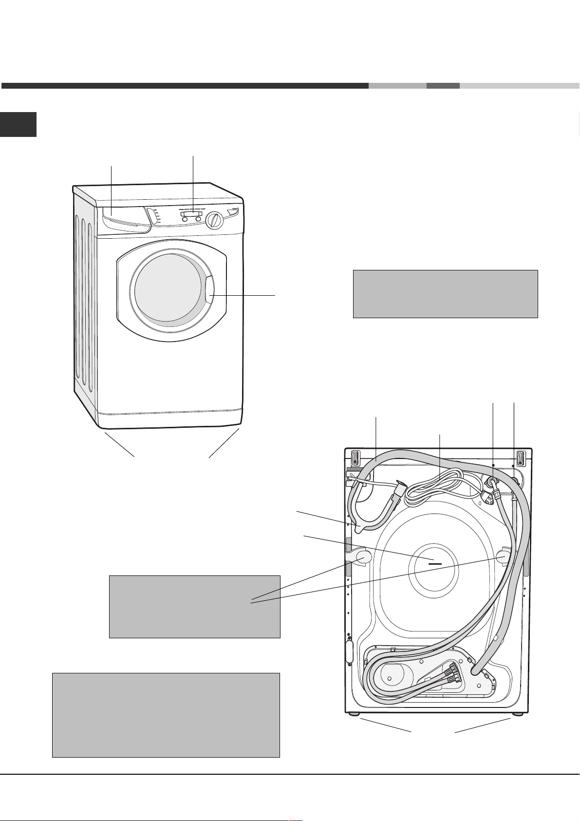
Description
Control panel
(
Varies by Model)
Dispenser drawer
Front adjustable feet
Interlocking door
and release lever
Hooked end support
Plumbing indicator line
Please record the Model number and
Serial number of your machine located
behind the door for future reference.
Hot and Cold water
inlet points
Drainage hose
Power cord
Two shipping bolts under
the plastic covers !
BOTH must be removed BEFORE
you use your machine (see page 6)
! The machine was designed and built in
compliance with the appliance international
safety regulations.
The following information is provided for your
safety and should consequently be read
carefully.
2
Back feet
Page 3
Important Safety Instructions
INTRODUCTION
Congratulations on your new Ariston washing machine. This is a highly sophisticated engineered product that
will give you many years of satisfaction. Please spend a few moments reading the Owner Manual. This will
show you ways to best utilize your valuable purchase
Save these instructions
Your washing machine has been built in compliance with the strictest international
safety regulations, to protect you and all your family
WARNING
To reduce the risk of fire, electrical shock, or injury to persons when using
your appliance, follow basic precautions, including the following:
NA
1. Read all instructions before using the appliance.
2. Install and level the clothes washer on a floor that
can support the weight.
3. This appliance must be properly grounded. Never
plug the appliance cord into a receptable which is not
grounded adequately and in accordance with local and
national codes. See installation instructions for grounding
this appliance.
4. To avoid the possibility of fire or explosion:
- Do not wash articles that have been previously cleaned
in, washed in, soaked in, or spotted with gasoline, dry
cleaning solvents, other flammable, or exlosive
substances as they give off vapors that could ignite or
explode.
- Do not add gasoline, dry cleaning solvents, or other
flammable or explosive substances to the wash water.
These substances give off vapors that could ignite or
explode.
- Under certain conditions hydrogen gas may be
produced in a hot water system that has not been used
for 2 weeks or more. HYDROGEN GAS IS EXPLOSIVE.
If the hot water system has not been used for such a
period, before using a washing machine, turn on all hot
water faucets and let the water flow from each for
several minutes. This will release any accumulated
hydrogen gas. As the gas is flammable do not smoke
or use an open flame during this time.
- To reduce the risk of fire, clothes, cleaning rags, mop
heads and the like which have traces of any flammable
substances, such as vegetable oil, petroleum based
oils or distillates, waxes, fats, etc. must not be placed in
the washing machine. These items may contain some
flammable substances after laundering, which may
smoke or catch fire by itself.
5. Always be sure to unplug the washing machine
from the electrical supply before attempting any service.
6. Do not insert/pull out the mains plug with wet hands.
7. Do not pull out the mains plug by tugging the cable.
To reduce the risk of fire or electrical shock, DO NOT use
an extension cord or an adapter to connect the washing
machine to the electrical power supply.
8. Caution when draining hot water.
9. The washing machine must only be used for its intended
purpose.
10. Make sure that all water connections to the washing
machine have shut-off valve(s) and that they are readily
accessible. Close the washing machine shut-off valve(s) at
the end of each wash day.
Check the fill hose connections on a regular basis to assure
that they are tight and not leaking.
11. Do not allow children to play on or in the appliance.
Close supervision of children is necessary when the
appliance is used near children.
12. Before the appliance is removed from service or
discarded, remove the door.
13. Do not reach into the appliance if the tub or drum is
moving.
14. Do not install or store this appliance where it will be
exposed to the weather.
15. Do not tamper with controls.
16. Do not repair or replace any part of the appliance or
attempt any servicing unless specifically recommended in
the user-maintenance instructions or in published user-repair
instructions that you understand and have the skills to carry
out.
17. Do not use fabric softeners or products to reduce static
unless recommended by the manufacturers of the fabric
softener product.
18. Do not machine wash fiberglass materials. Small
particles can stick to fabrics washed in following loads and
cause skin irritation.
19. Inlet hoses are subject to damage and deterioraton
over time. Check the hoses periodically for bulges, kinks,
cuts, wear or leaks and replace them every five years.
3
Page 4
NA
Technical details
Model AW 149
Dimensions
Capacity
Electric
connections
Water
connections
Spin speed
U
®
L
C
US LISTED
23.4" (59.5 cm) wide
33.4" (85 cm ) high
23.6" (60 cm ) deep
from 2 to 15 L bs (7 kg)
voltage 1 20 Volts 60 Hz
maximum pressure 100 psi (689.6 kPa)
minimu m pres sure 20 psi (137.9 kPa)
drum capacity 54 litres
up to 1400 rpm
Th is app liance w as tested by UL
and conform s with bo th Canadian
and U.S. UL s afety requ iremen ts
and displays their Mark
Indesit Com pany offer their
cus tomers products w ith the
ENER GY STAR Label
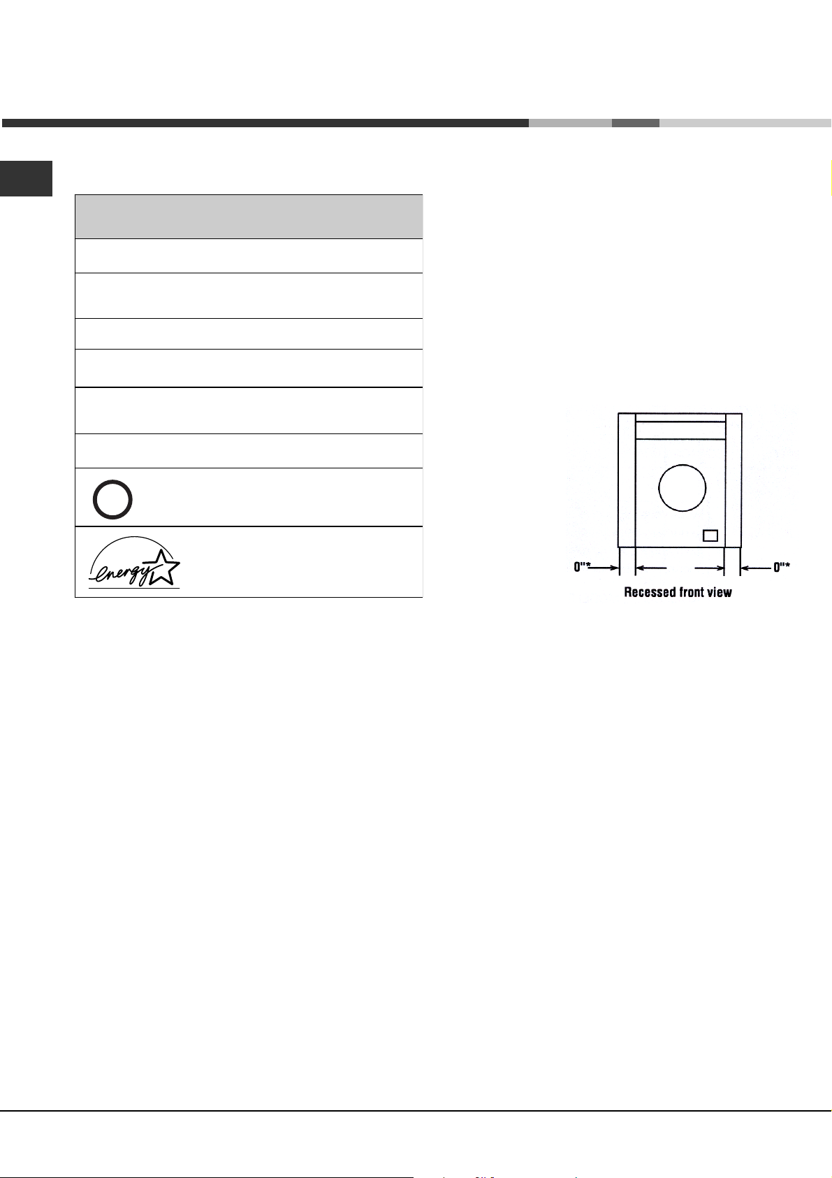
RECESSED, CLOSET AND ALCOVE
INSTALLATION (Instructions)
The machine may be installed in a recessed area,
closet or alcove.
The installation spacing is in inches and is the minimum
acceptable.
Additional spacing should be considered for easy
installation, servicing and in compliance with local codes
or ordinances.
Other installation must use the minimum dimensions
indicated .
Minimum
installation
spacing
* Additional clearances
for wall, door and floor
moldings maybe required.
As a result of technological progress, the manufacturer reserves the right to make any improvements to its
appliances without giving prior notice to its clientele.
4
Page 5
Unpacking
! Keep this instruction book on hand in order to refer to it when necessary. Take it you when you move, and
should you sell this appliance or pass it on to an other party, make sure that this booklet is supplied along with
the appliance so that the new owner may be informed about warnings and suggestions on how the works.
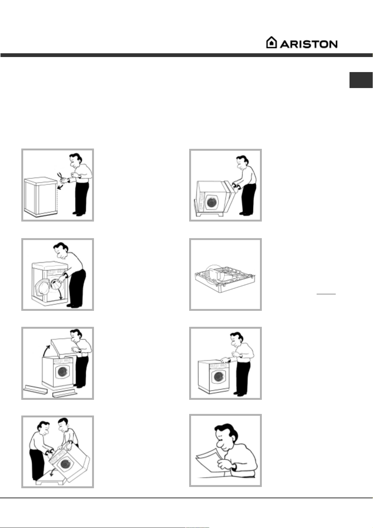
Unpacking
NA
1. Using scissors, cut
carefully along one
corner post to remove
the film.
2. Open the door, check
inside the drum and
remove the
accessories bags.
! Retain all packaging
material until
installation is
complete.
5. Remove the polystyrene
base.
! IMPORTANT check
when unpacking
your machine:
! This is the part of the
polystyrene base and should
have stayed intact when
you removed the base.
If it has broken off and is still
in the machine
it while the machine is still
laying on its side on the top
cap.
remove
3. Lift of the polystyrene
top cap and remove the
four corner posts.
4. Carefully lay the left side
of the machine down
onto the top cap.
! We reccomend that
a second person help
to raise and lower
the machine.
7. Stand the machine
upright.
Protect the environment
Please dispose of the
packaging material carefully
and considerately.
! Continue to read the rest
of these instructions
carefully; the following
pages contain important
information on installation
and troubleshooting.
5
Page 6
NA
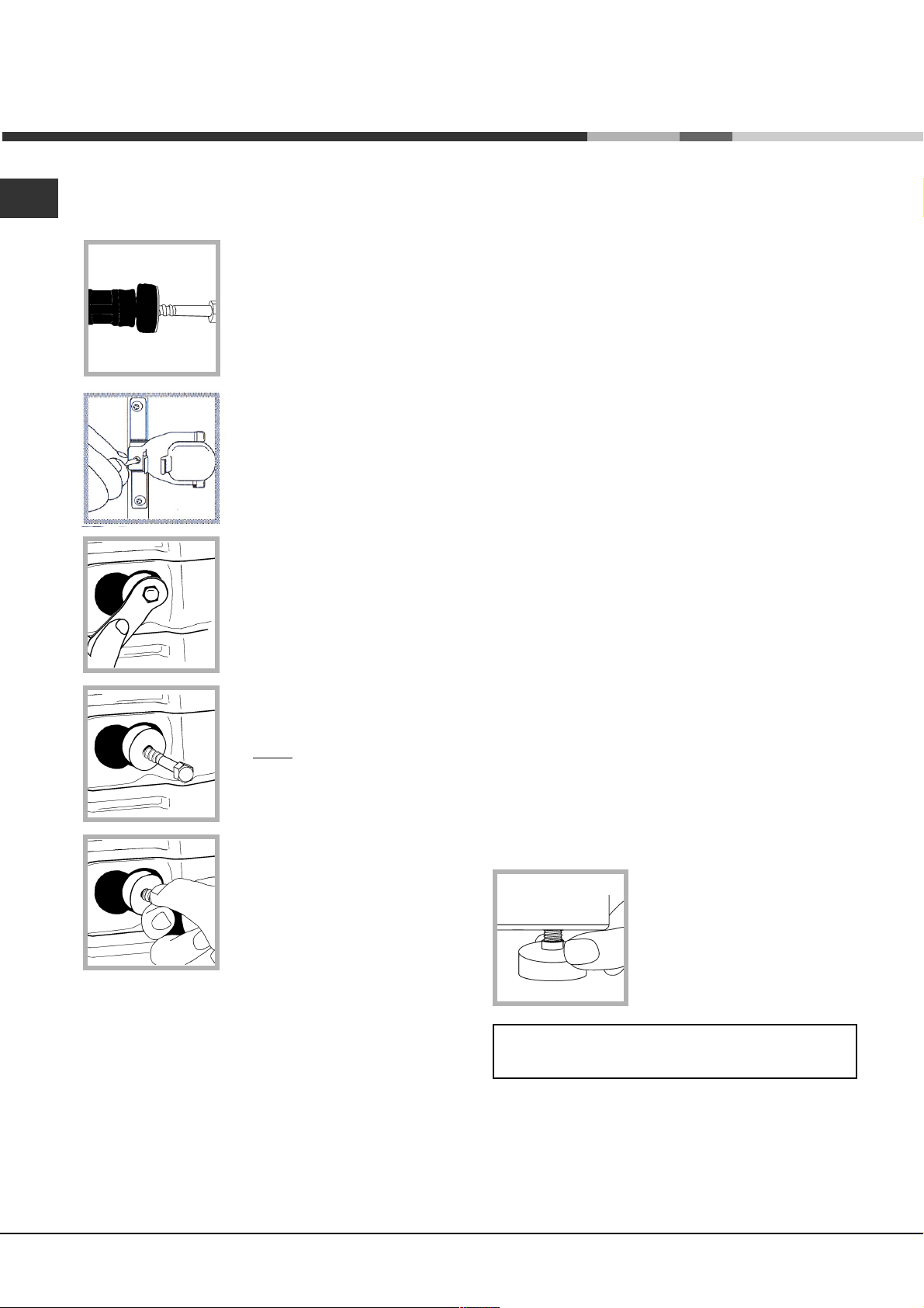
Remove the Shipping Bolts
IMPORTANT: Read these instructions to remove the 2
shipping bolts (see Description
for location). Situated on one
either side of the rear panel,
BOTH shipping bolts MUST be
removed before use.
! Failure to do so may cause
damage to your machine.
It is important the transit bolt and
spacer (see pic) come out intact.
1. Use a crosshead screwdriver
to remove the yellow plastic
covers.
Location
Where you install your machine will affect its performance:
! For your safety and to comply with electrical
regulations, seek professional advice if you want to install
your machine in a bath or shower room.
Make sure that the electrical socket and water taps are
easily accessible. You should switch off the machine's
electrical and water supplies when you are not using
it for extended periods.
Make sure that you allow enough space for the
machine. Select a space at least 23.6 (60 cm) wide,
23.6 (60 cm) deep and 33.4 (85 cm) high. Also
leave enough space to open the door fully, so that you
can load and unload it easily.
Where possible, the machine should be positioned on
a solid floor to minimise vibration.
Take care when you move the machine not to rip any
floor coverings. The weight of the machine may cause
indentations in some floor coverings.
2. Unscrew the bolt using a 13
mm wrench.
3.
STOP when 3 threads can be
seen.
4. Hold, slide sideways and pull to
remove.
5. For safety, replace both yellow plastic covers over the
holes left by removing the two bolts.
Did you know?
Levelling
Your machine will be noisy if the two front feet are not
adjusted so that the machine stands firm and level.
! The machine should be levelled from side to side and
from front to back.
1. Move your machine into its final location.
- Take care not to trap or kink the hoses.
2. Turn one or both front feet counter-clockwise by hand
until the feet cannot be turned any more.
When adjusting the feet, use a spirit level to check the
machine stands level, from side to side and from front to
back.
The spring on each foot will stop
them coming loose.
! If it is placed on a fitted or loose
carpet, adjust the feet in such a
way as to allow enough room for
ventilation beneath the machine.
! Packaging materials are
not children's toys.
the shipping bolts are fitted to ensure that your machine is undamaged during delivery.
...both of the shipping bolts must be removed before using the machine, not doing so will lead to
excessive vibration, movement of the machine and could eventually lead to internal damage.
...the majority of problems with noisy machines are due to the shipping bolts not being removed,
closely followed by the feet not being adjusted correctly to level the machine.
...you will be charged for a service engineers visit if a problem with your machine is caused by
incorrect installation or misuse.
6
Page 7
Installation
Water Connection
Caution
1. The washing machine must only be operated
with cold and hot (max. 140°F//60°C) tap water.
Do not connect the appliance to the mixer tap of an
unpressured hot-water boiler.
2. To prevent water damage, the hot and cold water
valves should be accessible when the washer is in
place and should always be turned off when the
washer is not in use.
! Remember: please use the new hoses supplied,
fitted to the machine. Old hoses may cause leaks due
to worn out washers or may be split due to water
pressure.
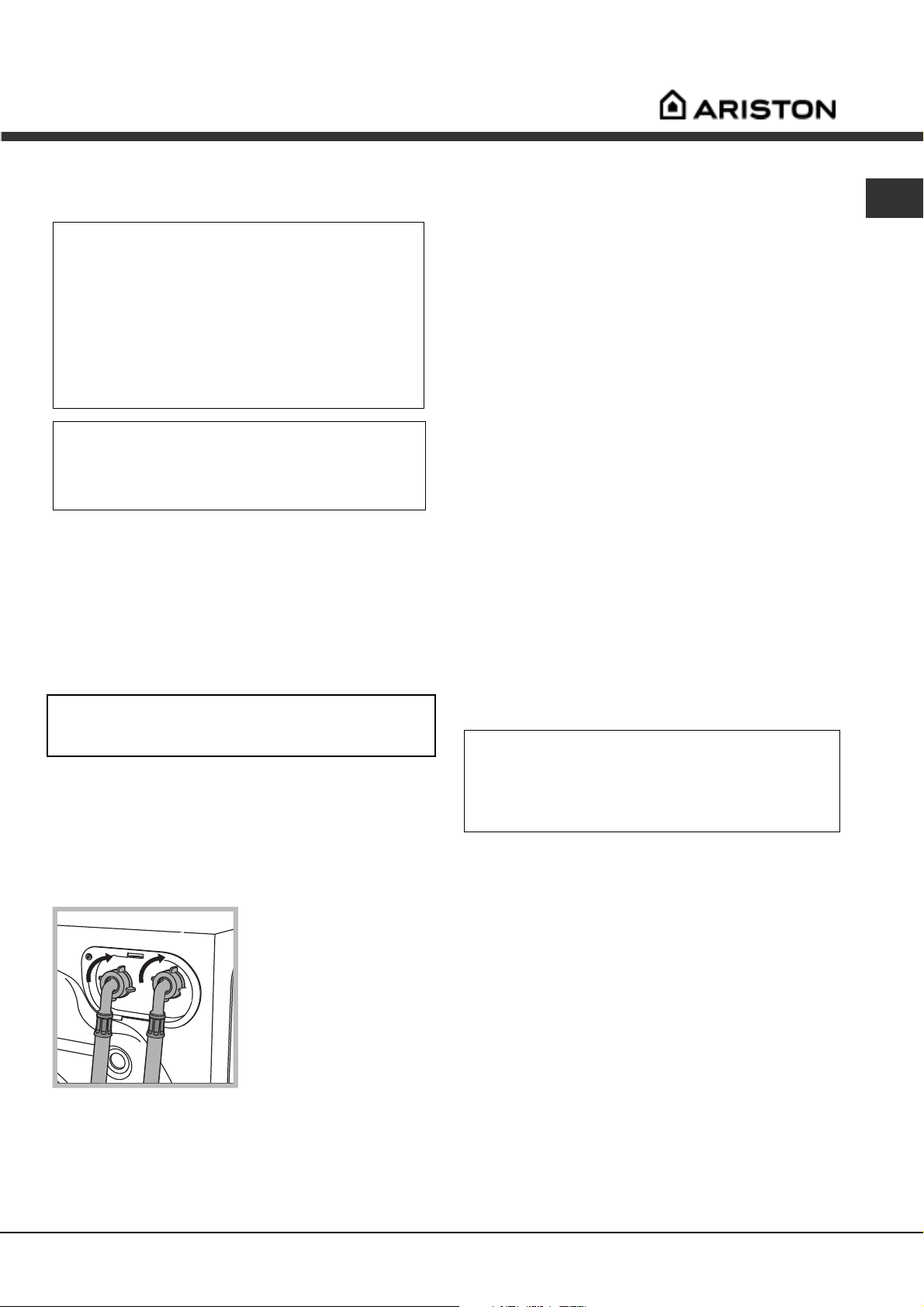
Connecting the water inlet hoses
Included in the accessories supplied with the machine
are 2 inlet hoses and 4 rubber washers. The straight end
of these hoses should be connected to the supply.
The 90° angled end of these hoses should be connected
to the inlet valves on the back of the machine to make a
water tight seal on each connection (see below figure).
The couplings should be tightened by hand, a tool should
only be used if a leak occurs. Do not use excessive
force.
Repair or replacement of a part should be made only by
a qualified service technician to prevent personal injury or
damage to the machine. Inlet valves are color coded:
Red = Hot / White = Cold
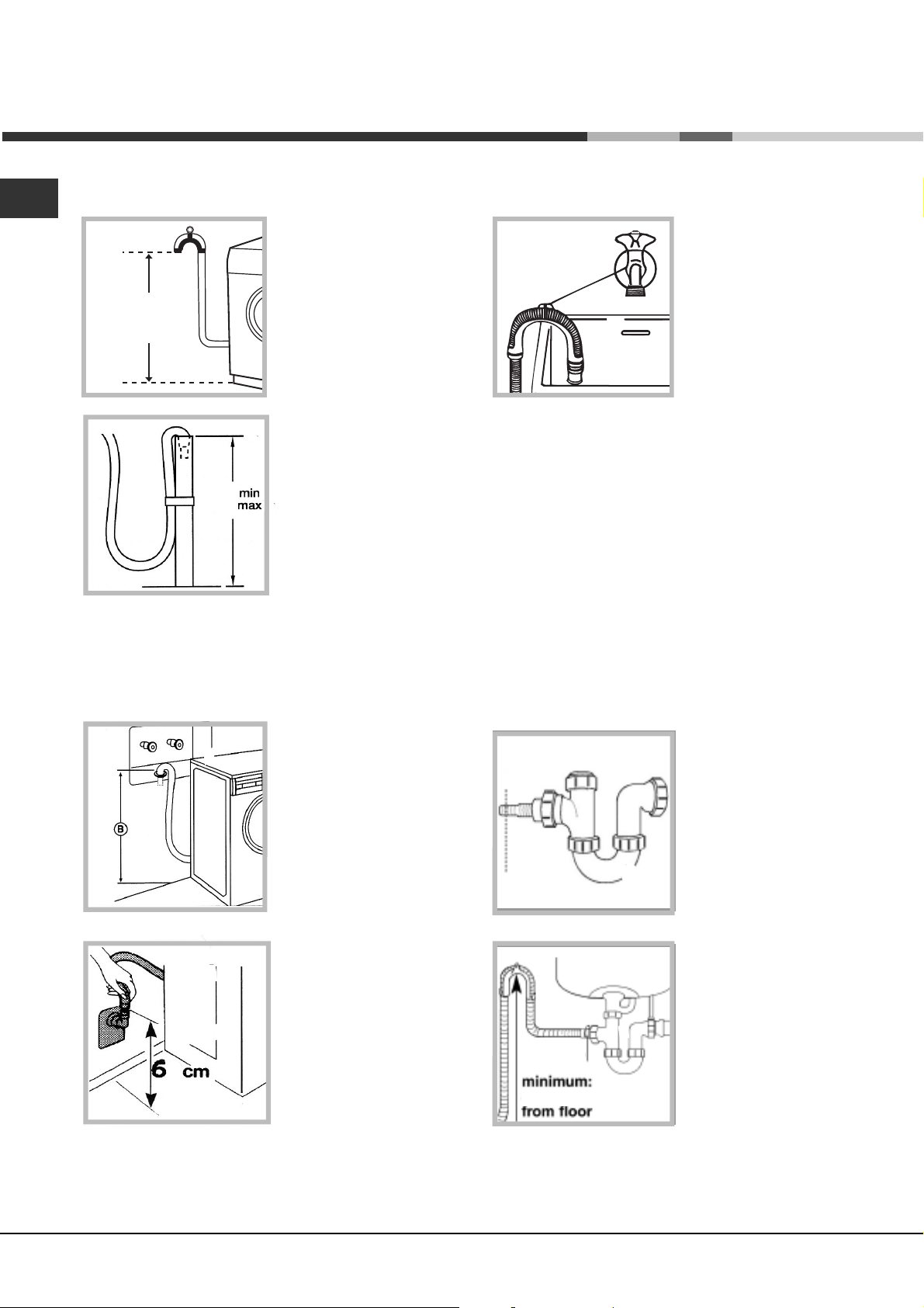
Drainage Connection
Standpipe Diameter/Capacity. Needs a 1 1/4 minimum
diameter standpipe with a minimum carry-away capacity of
7 gallons per minute.
Top of Standpipe. Must be between 25 - 34 inches (6286 cm) high measured from the bottom of the machine.
Outlet End of Drain Hose (provided with the unit).
Must be at least 20 above the bottom of the washer. An
air break must be available at the standpipe to avoid
siphoning. No more than 6 of the drain hose should be
inserted into the drain pipe to prevent siphoning.
! Although you may need to move the hooked end support
along the grey drainage hose,, DO NOT remove it.
! Whichever draining method you use, make sure that the
hooked end support is fixed level to, or above the
Plumbing Indicator Line.
You should carefully position the drain hose to avoid
kinks and ensure proper drainage of the water.
The outlet end of the drain hose must be at least 25 (62
cm) above the base machine. At this point it s possible
for the water to be discharged into a sink or drain pipe, but
an air break must be available at this 24 height to prevent
the machine from syphoning (see figures page 8).
No more than 6 of the drain hose should be inserted
in the drain pipe.
Important.
Make sure that the drain hose is not kinked and the
water flow has not been restricted.
The machine must rest solid on a sturdy floor for
optimum performance and minimum vibration.
NA
Connection.
1. Screw the cold water
H
C
onto the hot water supply until tight.
4. Turn on the hot water supply and check for leaks,
tighten if necessary.
fill hose (C blue connector)
onto the cold water supply
until tight.
2. Turn on the cold water
supply and check for
leaks, tighten if necessary.
3. Screw the hot water fill
hose (H red connector)
Hints and tips
! Make sure there are no kinks or bends in the
hose.
! The water pressure at the supply tap must be
within the values indicated in the Technical
details table (see table on page 4).
Always use a new inlet hose.
Check the water inlet hose at least once a year,
replace if cracked as worn hoses could split under
water pressure.
Do not overtighten. The couplings should be
tightened by hand; a tool should only be used if a
leak occurs. Do not use excessive force.
7
Page 8
Installation
NA
Floor Standpipe Drain
(A)
25"-34"
62 - 86
inches
cm
25”
34”
Top of standpipe must
be at least 25 inches (62
cm) high and no higher
than 34 inches (86 cm)
from the bottom of the
washer (A).
Sink Drainpipe Method
Entry into the sink drain
system must be above the
trap (see fig. aside ).
When routing the drain
hose through cabinets or
walls use aprotective
material such as
electrical duct tape to
cover sharp edges that
could damage the drain
hose. Use a suitable
clamp to secure the drain
hose to the Y branch or
the disposer. With a sink drainpipe system (see figures
aside and below), you may connect directly:
1) to a disposer by following the manufacturers
attachement method.
2) directly to a Y branch tail piece (Available at
most hardware stores).
3) through the floor to a separate trap. The trap
must be vented to prevent siphoning. To provide
proper venting , install an Air Gap Kit (available at
most hardware stores).
4) To the faucet using a Faucet Adapter Kit (available
separately). It will supply water from your faucet and
discharge water directly into your sink drain.
Wall Standpipe Drain
#^
Top of standpipe must
be at least 25 inches
(62 cm) min.; 34 inches
(86 cm) max from end of
drain hose to bottom of
washer (B) (See figures
aside and below).
Under Sink Method
Hose
clamp
620 mm
1. Cut the blocked end of
the under sink drainage
unit.
2. Fix the hooked end
supporta minimum of
620 mm from the floor.
3. Use a hose clip clamp
to securely attach the
grey drainage hose
end to the under sink
drainage unit using a
hose. clamp
8
Page 9

Electrical connection
Machine Voltage/Amperage - 120V, 60 Hz, 11 Amp.
Connection - 3-prong plug with 6 cord is provided
with the machine.
Circuit/Protector - 3-wire single phase, 120V, 60 Hz, AC,
on a separate 15 Amp circuit.
Final installation checklist
Instructions and Installalion Kit have been
removed from the tub.
Shipping straps have been removed.
NA
GROUNDING INSTRUCTIONS
This appliance must be grounded. In the event of malfunction,
or beakdown, grounding will reduce the risk of electric shock
by providing a path for electric current. This appliance is
equipped with a cord having an equipment grounding
conductor and grounding plug. Plug into an appropriate outlet
that is properly installed and grounded in accordance with all
local codes and ordances. DO NOT modify the plug provided
with the applliance. If it will not fit the outlet, have a proper
outlet installed by a qualified electrician.
WARNING: Improper connection of the equipment-grounding
conductor can result in a risk of electric shock.
Check with a qualified electrician or serviceman if
you are in doubt as to whether the appliance is
properly grounded.
Attention !
For your own protection and to prevent accidents, injury
and fire, please read the following carefully before
installing the washer.
Installation and grounding must be done in accordan ce with local codes and by a qualified installer.
Instalation instructions provided in this booklet are for
the installers reference.
Washer is plugged into electrical outlet and is
properly grounded.
Water hoses are connected to the faucets with
inlet screens and washers
Water is turned on and checked for leaks at
faucet and water valve connections.
Drain hose is properly located into drain
facility and is not collapsed or damaged.
Washer has been leveled.
Test for proper operation by running the
washer through a complete cycle at max
temperature.
Shipping bolts removed.
Washer MUST be installed on a strong, level floor and
in a protected dry and well-ventilated area close to a
power supply and drain outlet of sufficient capacity.
DO NOT install on carpet.
Important :
Installation on carpet floors will cause the machine to
vibrate and may result in excessive machine vibration
during the spin cycles and loss of performance.
The washer should be plugged into a properly grounded
(3) prong electrical outlet capable of 120 Volt, 60 Hz, and
11 Amp. It shouldnt be controlled by a wall switch or pull
cord which could be turned off accidentally. For your safety,
the third or round grounding prong must never be
removed. DO NOT USE AN EXTENSION CORD.
DO NOT install or store this appliance where it will be
exposed to weather or in an area where gasoline or other
flammables are stored.
9
Page 10

NA
Washing machine description
Control panel AW 149 (NA)
Warning: To reduce the risk of fire, electric shock, or injury, read the
IMPORTANT SAFETY INSTRUCTIONS, before operating this appliance.
Program listing
Detergent dispenser
OPTION
Buttons
Control panel features
Program listing: To consult a straightforward chart of
the different programs available.
Display to program the washing machine and follow the
wash cycle progress (see opposite page).
Option buttons: To select the options available (see
Program Table and Option Modifiers).
Variable Temperature button: Use this option to
reduce the wash temperature below the maximum for the
program you have chosen.
PROGRAM
selector dial
STATUS INDICATOR
Lights
Display
VARIABLE
TEMPERATURE
Button
On/Off button: To turn the washing machine on and off.
Start/Cancel button: To start the program or to cancel
it, if incorrect settings were selected.
Program selector dial: to select the wash programs.
The knob stays still during the cycle.
Status Indicator lights: Shows if the door is locked
(when lit, the door cannot be opened) and the stage of
the program that the machine has reached (wash, rinse
or spin).
VARIABLE
SPIN SPEED
Button
START/
CANCEL
Button
ON-OFF
Button
Variable Spin Speed button: To reduce the spin speed
or exclude the spin cycle completely
*.
*
When you select a program and your you wish to change the spin speed, the machine will accept it only if the speed is
compatible with the program.
10
Page 11

Program and Option Modifiers
Option modifiers
Superwash:
Use this option to select a more intensive wash and time program for the cotton (Sanitary, Heavy cotton, Regular cotton,
Heavy synthetics) and synthetics-permanent press (Heavy synthetics, Regular Synthetics).
Pre-wash Button:
For heavily soiled loads, push this button to adf an extra wash to any wash program
(except the 4-7-10-11 programs).
Easy Iron Button (Rinse Hold):
This option reduces the amount of creasing on fabrics, making them easier to iron.
Selecting this option the washing machine will reduce wash action and spin speed (max 600 rpm) for programs
5-6-7 and the machine will stop on the last rinse.
For the Silk program the Easy iron (stop with water) option is automatically carried out also if the button Easy iron is not
pressed: the washer will pause the cycle in the final rinse with laundry soaked.
The machine will stay in this state until either the Start/Cancel button is pressed or the Easy iron is pressed again to finish the
cycle .
Time Delay up to 24 hours:
Use this option to delay the program start by up to 24 hours. The display will show the delay chosen. Each press of the
button increases the Time delay in increments of 1 hour. If you press the button again after 24 shows in the display the
machine will reset the Time Delay and show OFF in the display, pressing the button after this start the Time Delay selection
from 1 hour. Once the countdown reaches zero the program will start.
NA
Soaking:
This option allows you to leave your washing to soak for one hour during the wash cycle.
During this time your washing machine tumbles every 2 minutes for 6 seconds (excepts 7, 8, 9, 10, 11 programs).
Variable Spin Speed:
Use this option to reduce the spin speed below the maximum for the program you have chosen.
Each press of the button will reduce the spin speed. The new spin speed will be shown in the display.
If you press again after OFF has been displayed, the machine will revert to the original higher spin speed.
N.B.: The washing machine will automatically prevent you from selecting a spin speed higher than the
maximum speed for each program.
Variable Temperature:
Use this option to reduce the wash temperature below the maximum for the program you have chosen.
The allowed selections are: 1: Cold (cold wash/cold rinse)
2: Warm (warm wash/cold rinse)
3: Hot (hot wash/cold rinse)
4: Sanitary
The cycle Sanitary is the one in which the heater element works.
Warning: If you select an option unsuitable to the chosen program the corresponding LED will blink for
some seconds and then will go out.
If the the option selected is suitable to the chosen
program the button LED will stay on.
In the event of an anomaly, an error code will appear, such as F-01, which should be communicated
to the Service Centre (see page 22)
11
Page 12

Program and Options Modifiers
p
g
p
g
p
g
p
g
g
y
p
y
(*)
g
y
p
y
(*)
y
(*)
AW 149 (NA)
NA
Type of fabric and
degree of soil
Max
Load
Lbs
Program
knob
Pre-wash
(Option)
Detergent
for wash
Fabric
softener
tions
O
Length of the
cycle (min.)
without
Options
Description of wash
cycle
TIME DELAY
From 1 to 24 hour delay Start is delayed by 1 to 24 hours
COTTON
HEAVY DUTY
K
Soakin
Pre-Wash
er Wash
Su
Soakin
Pre-Wash
er Wash
Su
Soakin
Pre-Wash
er Wash
Su
Soakin
Wash cycle
and final spin cycles
170
Wash cycle
92
and final spin cycles
Wash cycle,
and final spin cycles
82
Wash cycle,
and final spin cycles
59
Rinse cycles, intermediate and final spin cycles
51
Draining and final spin cycle
16
, three rinse cycles, intermediate
, three rinse cycles, intermediate
three rinse cycles, intermediate
three rinse cycles, intermediate
White Colourfast items
y deep-cleaning cotton
(safel
items)
Exceptionally soiled whites
(sheets, tablecloths, etc.)
Regular
(Heavily soiled whites and fast
colors)
Light - Slightly soiled whites
and delicate colors
(shirts, jumpers, etc.)
Rinse cycles
Spin cycle
15 1
15 2
15 3
15 4
Sanitary
Heavy
Regular
Light
KKK
KKK
KKK
KK
PERMANENT
PRESS
K
Soakin
Pre-wash
Iron
Eas
er Wash
Su
Soakin
Pre-wash
Iron
Eas
er Wash
Su
Easy Iron
Wash cycle,
cycle
75
Eas
Iron
Wash cycle,
cycle
69
Eas
Iron
Wash cycle ,
delicate spin cycle
63
Eas
Iron
Rinse cycles, delicate spin cycle
42
Draining and delicate spin cycle
14
three rinse cycles, delicate spin
three rinse cycles, delicate spin
rinse cycles and
three
Heavily soiled fast color
synthetics
(baby linen, etc.)
Delicate color synthetics
(all types of slightly soiled garments)
Delicate color synthetics
(all types of slightly soiled garments
Rinse cycles
Spin cycle
)
7.5 5
7.5 6
7.5 7
Heavy
Regular
Light
KKK
KKK
KK
DELICATES
Delicates
, particularly delicate
Silk
garments and fabrics
silk, viscose, etc.)
(curtains,
Wool
Daily - Mixed
(Very short refresh for lightly soiled
mixed fabrics)
Drain Draining
6.5 8
6.5 9
3.5 10
7.5 11
Light
Silk
Wool
Daily
KKK
KKK
KK
KK
Pre-wash
Pre-wash
64
39
52
30
Delicates
, three rinse cycles, delicate spn
Wash cycle,
Draining
Wash cycle,
spin cycle (600 rpm)
Wash cycle,
spin cycle (800 rpm)
three rinse cycles,
(*)
four rinse cycles and delicate
two rinse cycles and delicate
Sanitary Special Program 1:
The Sanitary cycle is recommended for safely deep-cleaning stained cotton colorfast items. The high temperature (167°F75°C) eliminates harmful bacteria.
Important:
To cancel the wash program you have just press start button for at leat 5 seconds.
(*) For finishing the program press the button start.
12
Page 13

Detergents tips and laundry
Detergent dispenser
! Do not put any items into the drawer, other than
detergents designed to be released from the drawer, as
they may cause damage or blockage.
1
2
3
4
5
1 Drawer release catch.
2 Pre-wash detergent compartment:
Maximum 200 ml powder or
100 ml liquid
3 Main wash detergent compartment:
Maximum 400 ml powder or
200 ml liquid
4 Grate
Detergent tips
Dispense a correct amount of detergent so to get
better washings
Warning
AVOID RISK OF POISONING KEEPING
DETERGENTS AND ADDITIVES OUT OF
THE REACH OF CHILDREN !
We suggest you to measure out the quantity of
detergent (powder or liquid) according to:
The water hardness. This piece of information you
will get it from your local water authority.
The quantity of laundry.
The degree of soiling (see Programs on page 12).
The specifications of the detergent manufacturer.
NA
5 Fabric conditioner compartment:
Maximum 120 ml
Dispensing powder detergent
To achieve the best wash results the manufacturer's
recommended amount of detergent should be measured
and added to the main detergent compartment.
Adding fabric conditioner
Pour the recommended amount of fabric conditioner into
the compartrrent. Do not exceed the maximum fill line.
Pre-wash
When selecting prewash, add detergent to both the prewash and the main wash compartments.
Fabric softener
All fabrics, particularly towels, benefit from the use of fabric
conditioners in the final rinse. Items of laundry feel softer, are
more easily ironed and the clinging affect of synthetics is
considerably reduced.
Pour the softener into Additives compartment of the
detergent dispenser to the level indicated on the syphon. Under
no circumstances overfill, as the softener will immediately
syphon into the machine and in so doing, impair the wash
results.
Measuring the correct amount of detergent ensures
optimum washing results and conributes to
get a better environment.
We recommend HE (high Efficiency) detergents
because they are particularly designed to deliver
optimum performance from your front-loading washer.
Not using HE detergent could cause problems such as
oversudsing (mess on your floor) and/or a decrease in
wash performances.
Too little detergent:
The laundry is not cleaned properly and will eventually
become gray and stiff. Grayish brown spots (fat
globules) may appear on the laundry. The heater may
calcify.
Too much detergent:
Not environmentally friendly, excessive suds reduce
wash agitation producing poor washing, poor rinsing
results or may prevent proper spinning.
Adjust the amount for heavily or lightly soiled loads.
Use more if water is extremely hard, use less in soft
water. If garments have been pretreated, you will not
need as much (or any) detergent at all.
13
Page 14

Starting a wash Program
NA
Laundry preparation
Sorting
Clothes should be sorted from separate items which
could damage other garments. Sort items into loads
according to similar colors, fabrics, garment
construction and degrees of soil.
Color
Separate clothes into three groups: Whites and pastels,
medium and bright colors, Dark colors. Items which
bleed color should be washed alone.
Type of fabrics
Delicate items should be separated from sturdier items.
Fabrics that shed lint should be separated from the
ones which shed none or attract lint.
Garments constructions
Garments that may fray easily or that have unusual
trim require gentle care. These garments may be
washed in the loader using the knit cycle. If garments
are fragile and delicare, hand washing may be desirable.
Degree of soil
Heavily sopiled items should be separated from the
rest of the wash to prevent transfer of soil in the wash
water.
Fasten all hooks, zippers and buttons.
Turn knit garments wrong side
out to reduce the tendency of knits to pill. Fabric
pills are balls of fibers on the surface of the
garments and cause damage by wear or friction.
Remove loose dirt and sand.
Brush dirt from trouser cuffs; shake or vacuum rugs
to remove loose surface soil.
If buckle is washable,
place a scrap of material securely around the
ornament before washing and drying to prevent
scratching and damage to the machine. Remove
non-washable trims, buckles, buttons and belts.
Tie strings
belts and apron sashes into bows to avoid tangling
during washing.
Before loading the washer,
make sure the drum is empty.
Inspection
While sorting clothes into wash-loads, also inspect each
garments to see if it requires special care
(see table fabric care on page 16).
Pretreating
Remove stains, while they are fresh and easy to get
out. Try cold water first to remove unknown stains.
Hot water sets stains containing protein such as blood,
egg, meat and milk. To remove difficult stains, refer to
the removal Chart on page 17.
Preatreat heavily soiled areas,
cuffs, and centers of pillowcases.
Mend rips and tears, before washing, so further
damage is not done to garments.
Empty pockets.
Objects left in pockets such as crayon, pens or
markers, or tobacco crumbs may stain an entire wash
load. Paper issues will shred leaving bits on each item
in the washer. Remove coins and other foreign object
to prevent damage to the machine.
such as collars,
Prewash
Prewash excessively soiled clothes, such as work or
childrens clothes.
They often get very soiled. Prewashing with detergent
will help loosen the soil
14
Page 15

Washcare tips and Starting
Useful tips
Never use your washing machine to wash... torn, fraying or
non-hemmed linen. If it is absolutely neccessary, place it
in a bag for protection. Do not wash colored linen with
whites.
Watch the weights!
For best results, do not exceed the weight limits stated
below (figures show weight of dry garments):
- Resistant fabrics (heavy - regular-light cotton):
15 lbs (7 kg) maximum
- Synthetic fabrics (heavy-regular-light):
7.5 lbs (3.4 kg) maximum
- Delicate fabrics
6.5 lbs (3 kg) maximum
Denim Alert.
Some overalls have straps with hooks that can damage the
drum of your washing machine or other garments during
the wash. To minimize the risk, place hooks in the pocket
and fasten with safety pins.
- Pure new wool
3.5 lbs (1,8 kg) maximum
- Bathrobe lbs 6.5 (3 kg) maximum
NA
How much does it weigh?
1 sheet 11/4 lb (400-550 gr.)
1 pillow case 4 oz. (120 gr.)
1 tablecloth 1 lb (450 gr.)
1 bathrobe 2-3 lbs (900-1,300 gr.)
1 towel 5oz/1 lb (150-500 gr.)
Colored T-shirts, printed ones and shirts last longer if
turned inside out before washing.
Printed T-shirts and sweatshirts should always be ironed
inside out.
Wool cycle
For best results, we recommend you use very little
detergent, taking care not to wash more than 3.5 lbs (1,8
kg) of laundry.
Vacations: unplug the appliance.
It is recommended that you should unplug the machine
from the socket and turn off the water supply. Leave the
door ajar to allow air circulation to the draw and the door
gasket area. This will prevent unpleasant odours.
For more delicate garments:
protect underwear, tights and stockings and
delicate items by placing them in a linen bag
Understanding Fabric Care Labels
The symbols on labels of your garments will help you in choicing suitable wash program, the right temperature, wash cycles
and ironing methods. Dont forget to give a glance to these useful indications !
Machine Wash
Cycle
Water Temp.
Tumble
Dry
Special
Instructions
Normal/
Cotton Heavy Duty
Hot
(50oC/120oF)
Dry Do not
Cotton Heavy Duty
Line dry/
hang to dry
Permanent Press/
wrinkle resistant
Warm
(40oC/105oF)
Normal/
Drip dry Dry flat In the shade
Permt Press/
wrinkle resistant
Delicate/
Gentle
(30oC/85oF)
Delicate/
Gentle
Cold/Cool
tumble dry
Do not washHand wash Do not wring
Do not dry
Bleach
Symbols
Any bleach
(when needed)
Only non-chlorine bleach
(when needed)
Do not bleach
15
Page 16

Operating the washing machine
NA
On-Off / Selecting a program
1. Switch the machine on by pressing the On/Off button.
2. Load your laundry into the machine and shut the door.
3. Add the detergent and any fabric softener.
4. Turn the program selector knob to the required
program.
5. Select any options you require (see Option Modifiers).
6. Press the Start/Cancel button to start the program.
To stop or change a program:
1. Press the Start/Cancel button for 5 seconds.
2. Select Pump out on the program selector knob.
A typical wash load
Two wexampes of maximum load for different types of
fabric:
COTTON 2 Bath Towels
1 Hand Towel
6 Shirts
6 Blouses
1 Set of Pyjamas
4 Items of Underwear
2 Sheets
= 15 Lbs (7 Kg)
SYNTHETICS 2 Childrens Dresses
5 Shirts
5 Blouses
1 Set of Pyjamas
4 Items of Underwear
= 7.5 Lbs (3.5 Kg)
3. When the machine has finished emptying, turn the
program selector knob to the new program required.
You may need to add detergent .
4. Press the start button to start the program.
Automatic feature
Before washing, you can do a great deal to ensure better
results. Divide your garments according to fabric and
color. Read the labels, follow their guidelines
Unbalance load detection
The washing machine has an inbuilt feature to prevent it from spinning to fast with an unbalanced load.
When an unbalanced load is detected, the washing machine will attempt to redistribute the load in order to balance it
evenly to achieve full spin speed.
If this is not possible and an unbalanced load remains the spin speed will be reduced, depending on the amount of
unbalanced detected. This is to prevent the machine from damaging itself or its surroundings and to prevent excessive
noise from the washing machine.
If the spin result is unsatisfactory following a reduced spin speed attempt to rectify the unbalanced load, then on
completion of the program the load can be redistributed evenly in the drum by hand. Select a spin cycle.
Note: Do not attempt to spin heavy or absorbent single items as the machine cannot distribute these evenly.
If you need to wash a single item you will need to add some other items as ballast to allow the machine to
distribute the load evenly throughout the drum.
16
Page 17

Stain Removal Chart
NA
Blood
Rinse or soak fresh stain in cold water. Work detergent
into any remaining stain. Rinse. If stain persists, put a few
drops of ammonia on stain and repeat detergent
treatment. Rinse. If necessary bleach.
Candle Wax
Scrape off excess. Place stain between clean white
blotters or several layers of facial tissues. Press with warm
iron. Sponge with detergent. If dye spot remains, bleach.
Ketchup
Scrape of excess. Soak in cold water 30 minutes.
Pretreat with a detergent paste. Launder.
Chewing Gum
Rub with ice to harden. Scrape off excess with dull blade.
Sponge with cleaning fluid.
Chocolate or Cocoa
Soak 15 minutes in cold water. Rub detergent paste into
stain, then rinse thoroughly. Launder in hottest water safe
for fabric. If colored stain remains, sponge with hydrogen
peroxide, rinse and launder.
Coffee or Tea (Black)
Soak fresh stains immediately in cold water. Then use
bleach treatment with hottest water safe for fabric. Or if
safe for the fabric pour boiling water through spot from a
height of 1 to 3 feet. Launder.
Coffee or Tea (With Cream)
Rinse or soak in cold water. Work detergent into stain.
Rinse. Dry. If grease stain remains, sponge with cleaning
fluid. Repeat, if necessary. If stain remains, bleach.
Cosmetics: eye shadow, lipstick, liquid make-up,
mascara, powder, pancake make-up or rouge
Apply undiluted liquid detergent to stain, or dampen stain
and rub in soap or detergent paste until thick suds are
formed. Work in until stain is gone, rinse well. Repeat if
necessary. If color remains, bleach if safe for fabrics.
Cream, Ice Cream or Milk
Sponge stain with cool water or soak stain in cool water
for 30 minutes or longer. If stain remains, work a
detergent into spot then rinse. Bleach if necessary.
Deodorants and Antiperspirants
Wash or sponge stain thoroughly with warm water and
detergent; rinse. If stain remains, bleach with hot sudsy
water. Launder. You may be able to restore fabric color
by sponging with ammonia. Rinse thoroughly.
Egg or Meat Juice
Rinse in cold water. If stain remains, sprinkle with meat
tenderizer, let stand 15-20 minutes. If stain still remains,
sponge with cleaning fluid or diluted bleach. Launder in
hot water. The use of hot water first may set stain.
Dye
Rinse or soak in cold water. Work detergent into stain.
Rinse. If necessary, bleach. Stain is not always possible
to remove. A commercial color remover may also be
used.
Fabric Softener Stain
Rub with bar soap until stain has lightened. Rinse
thoroughly. Launder. Rubbing alcohol is sometimes
effective if the color of the garment can take it.
Launder. If desired, dry cleaning can be used.
Felt tip pen
Spray spot with cleaners suitable to this purpose.
Sponge stain thoroughly. Rinse with cold water. Reapply
cleaner if necessary .
Fruit, Wine
Soak fresh stains immediately with cool water. Then use
bleach treatment with hottest water safe for fabrics,
pour boiling water through spot from a height of 1 to 3
feet. Launder.
Grass
Work detergent into stain. Sponge with denatured
alcohol. Bleach, if necessary.
17
Page 18

NA
Grease or Oil
Scrape away excess. Rub detergent paste or a general
purpose liquid household cleaner into stain, rinse with
hot water. If stain remains, sponge thoroughly with a
grease solvent. Dry. Repeat if necessary. To remove
yellow stain, use a chlorine or oxygen bleach.
Ink
Some ball-point inks are set by water. First test a scrap
of cloth. Sponge stain repeatedly with acetone, or
rubbing alcohol. Hair spray is effective. Launder. Bleach
if necessary. Use amyl acetate on triacetate, arnel,
dynel and verel. Use acetone on other fabrics.
NOTE: Some inks cannot be removed.
Mildew
Brush off surface growth to keep mold spores from
spreading. Dip article into solution of 1/2 cup bleach per
1 gallon of cool sudsy water for 5 to 10 minutes. Rinse
well. Launder.
Perfume
Rinse in cold water. Rub undiluted liquid detergent or
a detergent paste into stain. Rinse. If stain remains,
bleach.
Perspiration
Wash or sponge stain thoroughly with warm water
and detergent paste. If perspiration has changed the
color of the fabric, restore it by treating with ammonia
or vinegar. Apply ammonia to fresh stains; rinse with
water. Apply vinegar to old stains; rinse with water.
Rust and Iron
Apply commercial rust remover, according to
manufacturers directions. Rinse. Or, if safe for fabric,
boil stained article in solution of 4 teaspoons of cream
of tartar to 1 pint water.
Scotch
Rinse or soak in cold water. Work detergent into
stain. Rinse. Bleach, if necessary. Stain may be
impossible to re move.
Mud
Let stain dry; then brush well. Rinse repeatedly in cool
water until mud comes out. Launder. (Hot soaps suds
set a red or yellow clay stain).
Mustard
Soak in hot detergent water for several hours. If stain
remains, bleach.
Nail Polish
Treat while fresh, scraping or wiping off as much as
possible, before it dries. Place stain face down on white
paper towels. Sponge back of stain acetone (nail polish
remover) or sponge with denatured alcohol and a few
drops of household ammonia. Sponge stain frequently.
Launder with water at temperature suitable for fabric.
Do not use acetone on acetate, arnel, dynel or rayon.
Paint
Sponge or soak in turpentine or solvent recommended
as a thinner on label. Launder.
Urine
Soak in cool water. If stain is dry, work a detergent
paste into the spot then rinse. If necessary, bleach.
Shoe
Polish Scrape off as much as possible. Pretreat with a
detergent paste; rinse. If stain persists, sponge with
rubbing alcohol (1 part to 2 parts water) or turpentine.
Remove turpentine by sponging again with warm
detergent solution or with alcohol. Bleach if
necessary.
Soft Drinks
Sponge with cold water, some stains are invisible
when they have dried, but turn brown when heated
and may be impossible to remove.
Tar and Asphalt
Act quickly before stain is dry. Sponge with grease
solvent or turpentine. Launder.
.
18
Page 19

Care and Maintenance
Switching off the water and
electricity supplies
Turn off the water tap after every wash. This limits
wear and tear on the machines water supply and
prevents leaks.
Disconnect the
appliance from the
electricity supply before
cleaning it and before
performing any
maintenance work on it.
To avoid risk of
explosion
Never use flammable
solvents to clean the
appliance
Cleaning the machine
The exterior of the appliance and all rubber parts may be
cleaned using a cloth soaked in warm soapy water. Do not
use solvents or abrasive products.
Cleaning the door bowl
Clean the internal surface of the door bowl regularly with a
soft cloth. A build up of soap powder and water hardness
residue may result in water leaking from the door.
Always leave the appliance dor ajar to prevent unpleasant
odors from forming
Cleaning
Cleaning the exterior
Use a damp cloth or silicon polish to clean the exterior
surfaces of the appliance.
Cleaning the dispenser drawer and compartments
It is advisable to clean the dispenser drawer regularly. Do
not try to clean any part of the dispenser drawer while the
machine is running.
1. Pull out the drawer until
it reaches its stop.
2. Press the drawer
release button to remove
the dispenser drawer
(see picture).
3. Clean and dry the
dispenser drawer,
syphons, grate and fabric
conditioner exit channel
(A), ensuring any build up
of detergent and fabric
conditioner fully removed.
Failure to do so may lead
to the machine leaking
A
from the dispenser drawer.
Also regularly clean the
outlet pipe area (B).
NA
Checking the water inlet hose
Check the water fill hose once a year. If you see any
cracks, replace it immediately: during the wash cycles,
high water pressure cold cause a cracked hose to split
open.
! Never use hoses hat have already been used.
Drum maintenance
Always leave the porthole door ajar to prevent
unpleasant odours from forming.
4. Relocate the disponser
drawer and push it firmly
back into place.
! Do not clean any part of
the machine with abrasive
cleaners, scouring agents,
acids, any bleach or metal
polish as they may cause
B
damage.
19
Page 20

Troubleshooting
NA
From time to time your machine may not operate as it should. Before calling for Assistance (see Service-Assistance),
make sure that the problem cannot be resolved easily using the following list.
Malfunction:
The washing machine will not switch on.
The wash cycle does not begin.
The washing machines fails to fill with
water.
The machine continuously fills and
drains water.
Possible causes / Solutions:
The plug has not been inserted into the electrical socket, or it has
not been inserted far enough to make contact.
There is no power in the house.
The porthole door has not been shut properly.
The START/RESET button has not been pressed.
The water tap has not been turned on.
The water inlet hose is not connected to the tap.
The hose is kinked.
The water tap has not been turned on.
There is no water in the house.
The water pressure is insufficient.
The START/RESET button has not been pressed.
The end of the outlet hose has not been fitted at a height between
25 - 34 inches (62 and 86 cm) from the floor (see Installation).
The free end of the hose is underwater (see Installation).
If If the dwelling is on one of the upper floors of a building, there
may be problems relating to water drainage, causing the washing
machine to load and drain water continuously. Special anti-
draining valves are available in shops and help to avoid this
inconvenience.
The water drainage system is not fitted with a breather pipe.
The machine does not drain or spin.
The washing machine vibrates too much
during the spin cycle.
The washing machine leaks.
The machine is locked and the display
flashes, indicating an error code (e.g. F-01,
F- ...) .
The programme does not include a draining phase: some
programs require manual draining (see Programmes and
options).
The Easy Iron option is enabled: to complete the program, press
the START/RESET button (see Programs and options).
The outlet hose is bent (see Installation).
The drainage duct is clogged.
The drum was not unlocked properly when the appliance was
installed. Remove shipping bolts (see Installation).
The washing machine is not level (see Installation).
The washing machine is trapped between cabinets and a wall
(see Installation).
The load is not balanced properly (see Operating the washing
machine).
The water inlet hose is not screwed on to the tap correctly (see
Installation).
The detergent dispenser drawer is blocked (for instructions on
how to clean it, see Care and maintenance).
The outlet hose has not been secured properly (see
Installation).
Switch off the machine and unplug the appliance; wait for
approximately 1 minute then switch it on again.
If the problem persists, contact Assistance.
20
Page 21

There is too much foam.
The detergent is not designed for machine washing (the packaging
should state that the product is for washing by machine, for washing
by hand or machine or similar).
Too much detergent was used.
NA
The washing machine door remains
locked
Wait for the LED to switch itself off before you open the appliance door.
! If the problem persists after the above checks have been carried out,
shut off the water tap, switch off the machine and contact Assistance
21
Page 22

Service
NA
Before calling for Assistance:
Check whether you can solve the problem on your own (see page 20);
Restart the programme to check whether the problem has been solved;
If this is not the case, contact an authorised Technical Service Centre on the telephone number provided on the
guarantee certificate.
! If the machine has been installed or used incorrectly, you may be charged for the maintenance callout service.
! Always request the assistance of authorised servicemen.
Notify the operator of:
the type of problem;
the appliance model (Mod.);
the serial number (S/N);
This information can be found on the data plate situated on the rear of the door of the washing machine.
CUSTOMER CARE,
SERVICE & PARTS : phone (888) 426-0825
22
Page 23

Warranties
STATEMENT OF WARRANTIES
ARISTON Clothes Washers
The warranties provided by (Ariston) in this statement of warranties apply only to Ariston clothes washer sold to the
first using purchaser by Ariston or its authorized distributors, dealers, retailers or service centers in the United
States or Canada. The warranties provided herein are not transferable.
Length of Warranty
1st Year Full Limited Warranty from the date of installation*
Ariston will repair or replace, free of charge, any component part that proves defective in conditions of normal home
use. Shipping and labor costs included. Waranty repair service must be performed by an authorized Ariston service
center.
2nd Year Limited Warranty from the date of installation*
Ariston will provide replacement parts, free of charge, for any component part that proves defective under
conditions of normal home use, labor charges excluded.
3rd - 5th Year Limited Warranty on Electronics from the date of installation*
Ariston will repair or replace free of charge, any microprocessor or circuit board that proves defective under
conditions of normal home use 3rd year through 5th year from the date of original installation, labor charges
excluded.
NA
3rd - 5th Year Limited Warranty on Motor from the date of installation*
Ariston will repair or replace free of charge, any motor or component part of the motor that proves defective under
conditions of normal home use, 3rdyear through 5th year, from the date of original installation, labor charges
excluded.
Lifetime Limited Warranty against Stainless Steel Rust Through from the date of installation*
Ariston wll replace your clothes washer, free of charge, with the same model or a current model that is equivalent or
better in functionality if the washer drum should rust though under conditions of normal home use, labor, shipping,
and installation charges excluded.
10 day warranty after purchase on cosmetic damages detected
Ariston will replace any cosmetic parts, free of charge - including labor, which are detected damaged with in 10
days after purchase. Any damages deemed caused by improper handing, shipping, or installation will not be
covered under this clause.
* Date of installation shall refer to the earlier of the date the clothes washer is installed or ten business days after
delivery date.
Exlusions:
This warranty does not cover repair or service calls to correct the installation, to provide instructions on the use of
your product, to replace house fuses or correct plumbing or the electric wiring in your home. In addition any repair
to the products that’s use was in a manner other than what is normal for home use is void of any warranty claim.
The warranties exclude any defects or damage arising from accident, alteration, misuse, abuse, improper
installation, unathorized service work, or external forces beyond Ariston control, such as fire, flood, and other acts
of God, or installation not in accordance with local electric or plumbing codes. Labor, shipping, and installation
charges incurred in the repair or replacement of any product after a period of one year from the date of installation
shall not be covered by this warranty. Any and all replaced or repaired parts shall assume the identity of the original
for the purposes of the applicable warranty period. To the extent permitted by law, this warranty is in lieu of all
other express and implied warranties, including the implied warranties of merchantability and fitness for a particular
purpose. Ariston does not assume any responsibility for incidental or consequential damages.
To obtain warranty services call 1-888-426-0825, or write to:
Ultra 8 International, 2505 Anthem Village Drive, Suite E - PO BOX 562, Henderson Nevada 89052
Be sure to provide: model number, serial number, purchase date, and the sellers name and address.
23
Page 24

NA
Ultra 8 International, 3027 East Sunset Road, Suite 101, LAS VEGAS Nevada 89120
24
 Loading...