

Page 1
13/06/06
Page 1 of 13
3782863
If you have any queries regarding the installation of this product please contact the distributor from whom it was purchased, or alternatively the ARB office in your state.
Head Office – ARB Corporation Ltd VIC: 42-44 Garden Street, Kilsyth, Victoria, 3137 Tel: (03) 9761 6622 Fax: (03) 9761 6807
WA: (08) 9244 3553 NSW: (02) 9821 3633 ACT: (02) 6280 7475 SA: (08) 8244 5001 QLD: (07) 3872 3872 NT: (08) 8947 2262 TAS: (03) 6331 4190
ARB WINCH/NON WINCH BUMPER TO SUIT MITSUBISHI PAJERO NM
FLARED. EXCLUDING EXCEED MODEL
PRODUCT No. 3934020 Sahara Bar
3034020 Sahara Bumper
FITTING KIT No. 6171383, 6171762, 6171363
WARNING
FOR VEHICLES EQUIPPED WITH SRS AIRBAG
WHEN INSTALLED IN ACCORDANCE WITH THESE INSTRUCTIONS, THE FRONT
PROTECTION BAR DOES NOT AFFECT OPERATION OF THE SRS AIRBAG.
TAKE NOTE OF THE FOLLOWING:
• THIS PRODUCT MUST BE INSTALLED EXACTLY AS PER THESE
INSTRUCTIONS USING ONLY THE HARDWARE SUPPLIED.
• IN THE EVENT OF DAMAGE TO ANY BULL BAR COMPONENT,
CONTACT YOUR NEAREST AUTHORISED ARB STOCKIST. REPAIRS OR
MODIFICATIONS TO THE IMPACT ABSORPTION SYSTEM MUST NOT
BE ATTEMPED.
• DO NOT USE THIS PRODUCT FOR ANY VEHICLE MAKE OR MODEL,
OTHER THAN THOSE SPECIFIED BY ARB.
• DO NOT REMOVE LABELS FROM THIS BULL BAR.
• THIS PRODUCT OR ITS FIXING MUST NOT BE MODIFIED IN ANY WAY.
Note:
1 If fitting optional fog lights, fitting kit no. 9381FCK is required.
2 This winch bumper is suitable for Warn 8,000lb & 9,000lb winch only.
Tools Required
10mm, 18mm, 19mm, 21mm Spanners and Sockets. Phillips head screwdriver,
12mm and 13mm drill bit and drill.
Page 2
13/06/06
Page 2 of 13
3782863
USE
PART No
QTY
DESCRIPTION
BUFFER FITTMENT
6151128
17
NUT FLANGE M6
3162158 1 BUFFER LOWER
3162153
1
BUFFER LHS SAHARA BAR
3162154
1
BUFFER RHS SAHARA BAR
3162471L
1
BUFFER LHS SAHARA BUMPER
3162471R
1
BUFFER RHS SAHARA BUMPER
LIGHT SURROUNDS TO BAR
3162156 1 LIGHT SURROUND LHS
3162157 1 LIGHT SURROUND RHS
CHROME TUBE FITTMENT
6151255 2 BOLT M12 X 40mm
(SAHARA BAR ONLY)
4581049 2 WASHER FLAT M12
4581050 2 WASHER SPRING M12
6131174 1 CHROME TUBE
MOUNT ASSY TO VEHICLE
3756190L
1
BRACKET IMPACT ABSORBER LHS
3756190R
1
BRACKET IMPACT ABSORBER RHS
3756194L
1
BRACKET FRONT MOUNT LHS
3756194R
1
BRACKET FRONT MOUNT RHS
3756189L
1
BRACKET CHASSIS SUPPORT LHS
3756189R
1
BRACKET CHASSIS SUPPORT RHS
6151246 6 BOLT M12 X 25mm
6151204 8 BOLT M10 X 35mm
4581010
4
WASHER Ø14 ID, Ø35 OD
4581041
12
WASHER FLAT M10
4581048 8 WASHER M10 SPRING
6151026
4
NUT M10
3193659 2 PLATE CAPTIVE NUT
6151255 6 BOLT M12 X 40mm
4581049 8 WASHER FLAT M12
PT003-12B 6 CAP RUBBER
6151026
4
NUT M10
4581050
12
WASHER SPRING M12
6151268 6 NUT CAPTIVE
WING BRACE TO
BAR/VEHICLE
4681081 2 BRACE WING
6151256
2
BOLT M6 BUTTON HEAD S/STEEL
4581072 2 WASHER M6 x 19mm
6151017
2
BOLT M6 X 16mm HEX HEAD
6151128 4 NUT M6 FLANGE
WINCH
4581044 4 WASHER 3/8”
CONTROL BOX FITTMENT
3756220
1
CONTROL BOX BRACKET
6151017 2 BOLT M6 X 16MM
6151128 4 NUT FLANGE M6
WINCH COVER FITTMENT
6151128 2 NUT FLANGE M6
6151256
2
SCREW M6 S/STEEL BUTTON HEAD
6191001
1
WINCH COVER EXTRUSION
6521031 1 WINCH COVER
6151046 2 WASHER M6
Page 3

13/06/06
Page 3 of 13
3782863
USE
PART No
QTY
DESCRIPTION
CAP WING COVER FITTMENT
6151267 6 CLIP CHRISTMAS TREE
3162164 1 CAP WING COVER LHS
3162165 1 CAP WING COVER RHS
6151180 4 BOLT M6 X 20mm
6151162 4 NUT M6 NYLOC
4581072 8 WASHER M6 X 19mm
BAR TO MOUNT ASSEMBLY
6151255 6 BOLT M12 X 40mm
4581050 6 WASHER SPRING M12
4581007
6
WASHER FLAT M12 LARGE
4581048 2 WASHER SPRING M10
6151026
2
NUT M10
6151045 2 BOLT M10 X 25mm
4581041
12
WASHER FLAT M10
CB
3162152 2 PLASTIC PLUG DIA16
ROLLER FAIRLEAD FITTMENT
4581049 4 WASHER FLAT M12
NUMBER PLATE FITTMENT
6151017 2 BOLT M6 X 16mm
6151128 2 NUT FLANGE M6
6781408 1 TAPE DOUBLE SIDED
WIRING
180302
10
CABLE TIE
Page 4
13/06/06
Page 4 of 13
3782863
ASSEMBLY SEQUENCE.
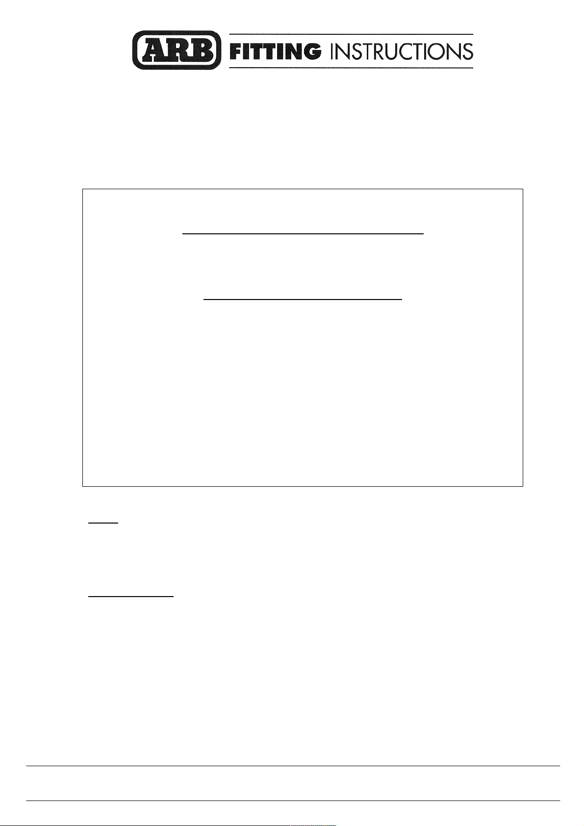
1. 1. Position the lower buffer on the winch
bumper and assemble using the M6 flange
nuts.
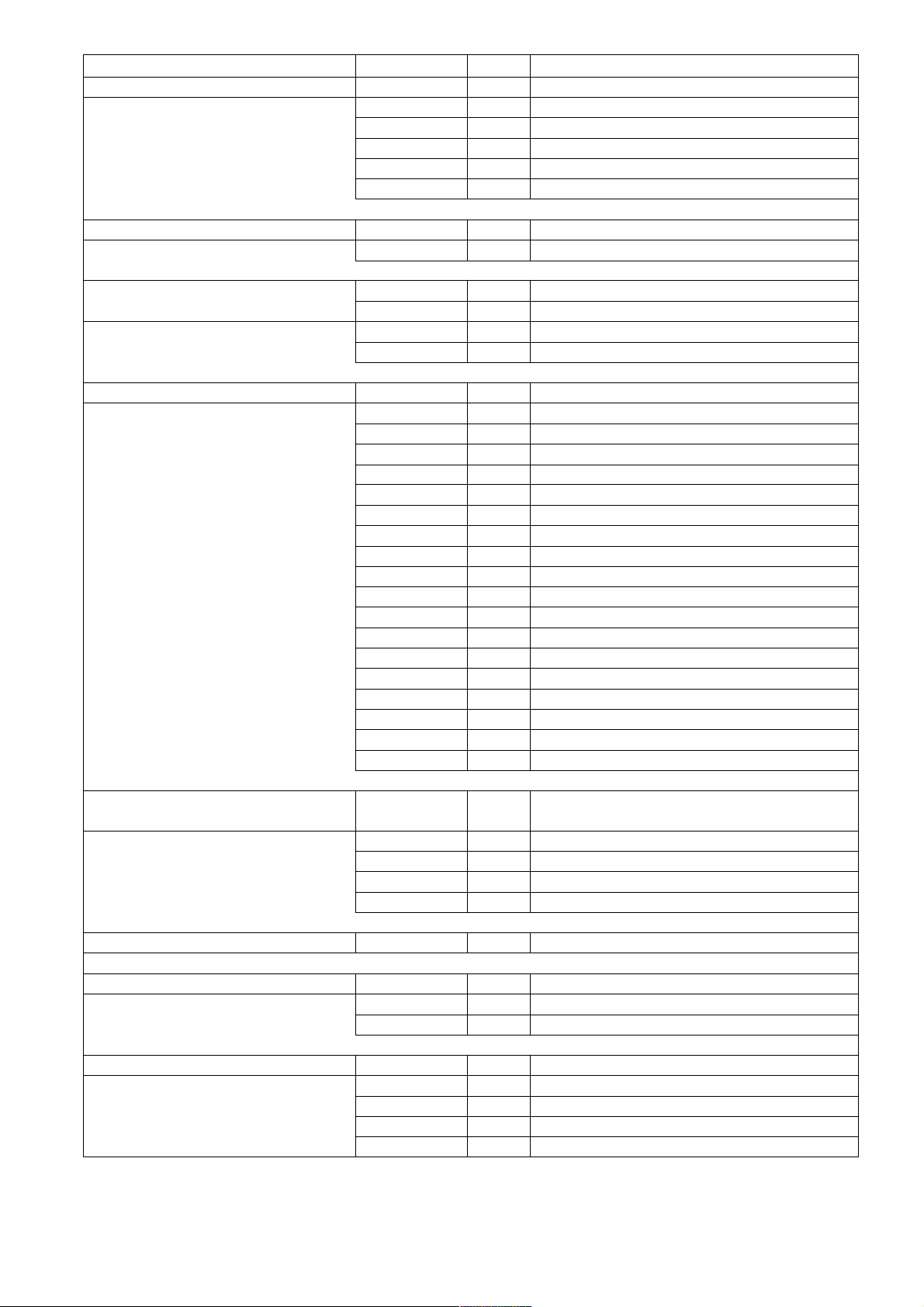
2. 1. Insert the side buffers through the holes and
fix using the M6 flange nuts.
NOTE
Sahara bumper buffer has no large top hole.
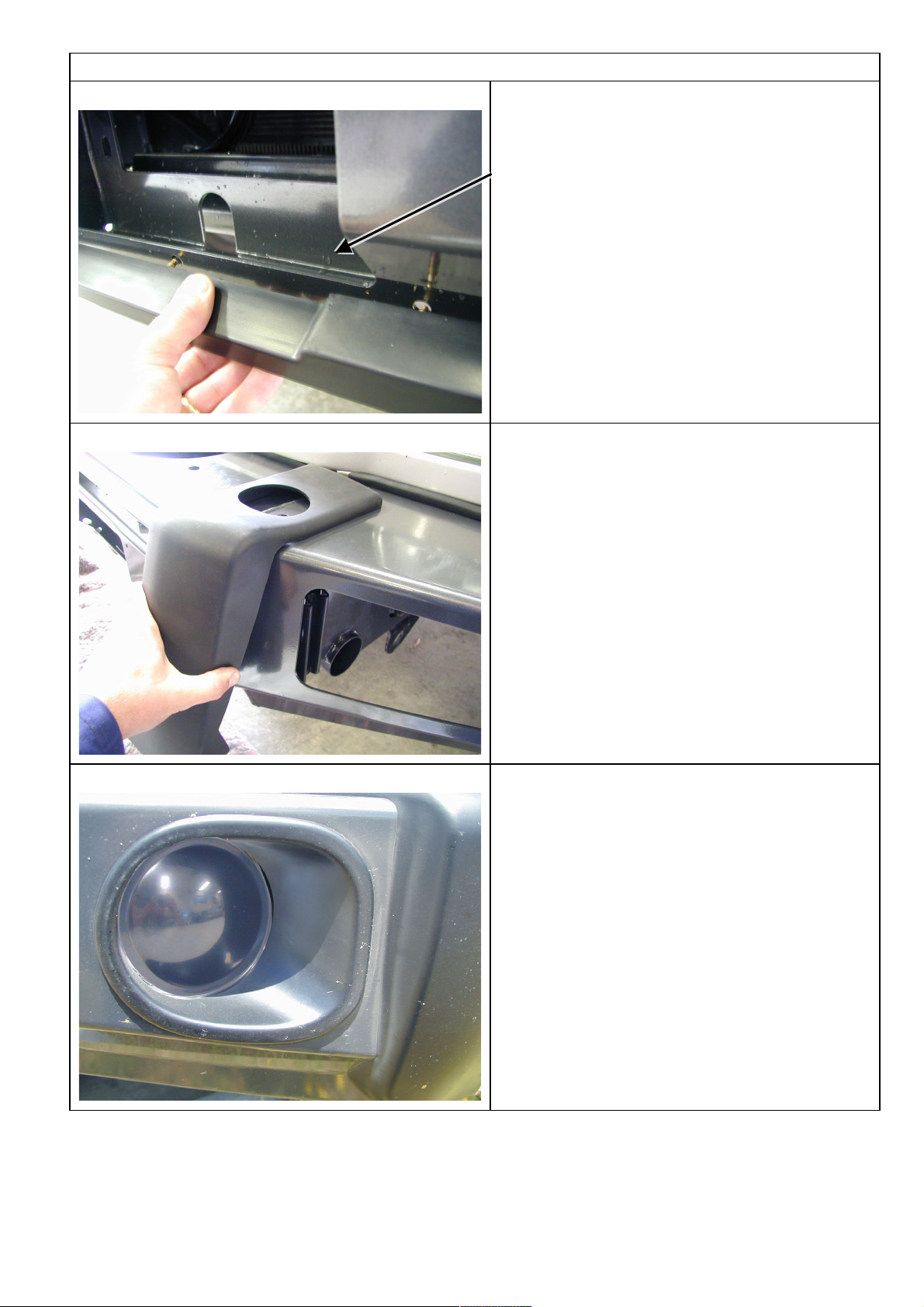
5. 1. Glue the light surrounds to the bar using a
silicone based rubber adhesive. Run the
bead along the cavity on the rear side of the
part. Position the surround to align the inside
edge with the buffer and concentric to the
light.
2. Wipe off any adhesive on the front face of
the bar. Allow adhesive to cure before
continuing.
3. If fitting optional fog lights, do so at this
stage.
4. If fitting Sahara Bumper go to step 7
Page 5

13/06/06
Page 5 of 13
3782863
6. 1. Push the top chrome tube through the hole in
the buffer and fasten using the M12 x 40mm
bolts, washers and spring washers.
NOTE
This step for Sahara bar only
7. 1. Remove the bumper bar and grill.
2. Spray paint the vehicles cross member with
matt black spray paint on both sides.
3. Assemble the mounts to the vehicle as
shown in the pictures 7 & 8. Fasten bolts
finger tight only.
M10 x 35mm bolts, flat washers, spring washers
and nuts.
8. M12 x 25mm bolts, flat washers and spring
washers.
Page 6

13/06/06
Page 6 of 13
3782863
9. 1. Using a 12mm drill bit, drill through the two
slot holes at the front into the chassis cross
member.
10. 1. Feed the captive nut plate through the hole in
the cross member and fasten using M10
bolts, flat washers and spring washers.
11. 1. Using a 13mm drill bit, drill through the holes
in the outside bracket and into the chassis
rail.
Page 7

13/06/06
Page 7 of 13
3782863
12. 1. Using a 13mm drill bit, drill through the hole
in the main bracket and into the chassis rail.
13. 1. The mounting bolts for the drilled holes are
fastened using the captive nuts with
extension arms. Feed these through the hole
underneath the chassis rail. The wire can be
manipulated to shape for easier installation.
14. 1. Fasten the brackets using the M12 x 40mm
bolts, Large washers and spring washers.
Note: The inside bolt uses a small M12 washer.
Page 8

13/06/06
Page 8 of 13
3782863
15. Note: The washer bottle on the drivers side must
be removed to gain access to the top bolt.
1. Tighten all bolts.
16. 1. Fasten the wing braces to the vehicle using
M6 bolts flange nuts and washers.
17.
(If fitting the winch.)
1. To place the winch clutch handle in a
convenient location the winch gearbox must
be rotated 2 hole spacings, 72 degrees, in an
anti-clockwise direction when viewed from
the gearbox end. Place the winch on its end
and remove all gearbox bolts. Gently raise
the gearbox just enough to rotate it. Do not
completely remove the gearbox and avoid
damaging the gasket. Refit all bolts and
tighten.
NOTE: Take care not to lift the assembly
more than a couple of millimetres while
rotating to the desired position to avoid
unmeshing the gears.
Page 9

13/06/06
Page 9 of 13
3782863
18.
1. To place the winch motor in the correct
location the winch motor must be rotated 90
degrees, in a clockwise direction when
viewed from the motor end. Place the winch
on its end and remove the 2 motor retaining
bolts. Gently raise the motor just enough to
rotate it. Do not completely remove the motor
and avoid damaging the gasket. Refit all bolts
and tighten.
NOTE: Take care not to lift the assembly
more than a couple of millimetres while
rotating to the desired position to avoid
unmeshing the gears.
19. 1. Bolt the winch and roller fair lead to the bar
using the bolts supplied. The longer bolts are
used for the two bottom holes through the
roller fair lead.
20.
1. Install the winch and roller fairlead using
bolts, nuts and spring washers supplied by
Warn, and the 4 x 3/8” flat washers supplied
in the bolt kit. Refer to Warn installation
instructions for correct procedure. Adjust
winch in slots until the winch is centralised in
the bull bar.
2. Assemble the control box bracket to the
control box using M6 flange nuts.
3. Mount the control box to the bar using M6 X
16 bolts and M6 flange nuts.
NOTE: The gearbox is on the passenger side
for the 8,000lb and 9,000lb. The cable spools
from the bottom for the two winches
mentioned.
Page 10

13/06/06
Page 10 of 13
3782863
21. (If not fitting winch)
1. Wrap rubber extrusion around winch cover.
2. Place washers over the winch cover fixing
holes located on the top middle face of the
winch bumper.
3. Place the winch cover on top of the winch
bumper inline with the mount holes.
4. Bolt together using the M6 button head
stainless steel screws and M6 nuts.
22. 1. Fasten the Cap Wing Cover to the bar using
the christmas tree clips, M6 x 20mm bolts,
washers and nyloc nuts.
Three christmas tree clips are used on the
inside holes.
The bolts are for the two end holes.
23.
With winch
Without winch
(If fitting with winch.)
1. Peel off one side of the double sided tape
and adhere to the top rear side of the number
plate. Note: Clean the adhering surfaces
before applying tape with an alcohol solvent.
2. Peel off the other side of the tape and bolt to
the winch bumper with the M6 X 16mm bolts
and M6 flange nuts through the lower holes
of the number plate.
3. Press firmly to the top of the number plate so
the tape can properly adhere.
(If not fitting with winch.)
1. Bolt the number plate through the top holes
using M6 X 16mm bolts and M6 flange nuts.
If desired the double sided tape can be used
down the sides of the number plate.
Page 11

13/06/06
Page 11 of 13
3782863
24. 1. With the aid of another person place the bar
on the mounts. Line the bar to the vehicle
and fasten using six M12 x 40mm bolts six
large washers and six spring washers.
Tighten all bolts so the large washer deforms
inside the rectangular cutout. Note: when
aligning the bar to the vehicle the plastic wing
trims can be adjusted along the side of the
wheel arches by undoing the two bolts and
repositioning. Note: if car is fitted with
headlight covers, remove them before fitting
the bar. Leave approximately a 2-3mm gap
between the plastic trim and headlight when
tightening the bolts. Fit the headlight covers
after bar is fitted.
25. 1. Bolt the wing brace to the back of the wing
using the button head M6 bolt and flange nut.
Note: The brace has adjustment so the wing can
be pushed up to the vehicle then tightened.
26. 1. Cut the excess wires from under the vehicle
so they don’t protrude past the chassis rail.
Page 12

13/06/06
Page 12 of 13
3782863
27. 1. Place the rubber caps over the cut ends of
the wires.
28. 1. Next step is to lock pin the bar so there is no
movement by drilling a 10mm hole on both
sides of vehicle, and fasten with 10mm x
25mm bolts plus 10mm hardware.
29. (If fitting with winch)
1. Feed the winch cable through the roller fair
lead. Mount the hook to the end of the cable.
Page 13

13/06/06
Page 13 of 13
3782863
30. 1. There are two dia 16 hole located on the top
face of the bar. If no CB arials are fitted the
holes can be covered with the plastic plugs
provided in the fitting kit.
2. Place the ARB logo on the front face of the
bar in the indentation.
31. If fitting fog lights, wire the fog lights as described in the fog light fitting instructions
The fog lights can be adjusted to desired angles by the adjustment bolts located at the back of the
light insert. When adjustment is finalised be sure to retighten the fog light bolts.
(If fitting with winch)
32. Connect the winch control box cables to the winch motor. Refer to the Warn handbook for additional
information. Connect the long winch + & - cables to the vehicle after the bar is installed.
Refer to the Warn winch manual for vehicle wiring instructions.
Ensure that these cables are installed well clear of sharp, hot or moving objects. Secure the
winch cables to the vehicle and winch bumper with the supplied cable ties.
 Loading...