

Page 1
13/6/08
Page 1 of 11
3786950
If you have any queries regarding the installation of this product please contact the distributor from whom it was purchased, or alternatively the ARB office in your state.
Head Office – ARB Corporation Ltd VIC: 42-44 Garden Street, Kilsyth, Victoria, 3137 Tel: (03) 9761 6622 Fax: (03) 9761 6807
WINCH/NON WINCH BUMPER TO SUIT LANDROVER DISCOVERY 2003 ON
PRODUCT NUMBER 3932100
FITTING KIT NUMBER 6172409
TOP TUBE & BUFFER KITS:
5100040: Top Tube Kit
5100020: Buffer Kit – With hole (required when fitting Top Tube)
5100030: Buffer Kit – With No Hole
WARNING
FOR VEHICLES EQUIPPED WITH SRS AIRBAG
WHEN INSTALLED IN ACCORDANCE WITH THESE INSTRUCTIONS, THE FRONT
PROTECTION BAR DOES NOT AFFECT OPERATION OF THE SRS AIRBAG.
TAKE NOTE OF THE FOLLOWING:
• THIS PRODUCT MUST BE INSTALLED EXACTLY AS PER THESE INSTRUCTIONS
USING ONLY THE HARDWARE SUPPLIED.
• DO NOT USE THIS PRODUCT FOR ANY VEHICLE MAKE OR MODEL, OTHER THAN
THOSE SPECIFIED BY ARB.
• DO NOT REMOVE LABELS FROM THIS BULL BAR.
• THIS PRODUCT OR ITS FIXING MUST NOT BE MODIFIED IN ANY WAY.
Page 2

13/6/08
Page 2 of 11
3786950
USE
PART No
QTY
DESCRIPTION
3756531
1 PAIR
BRACKET MOUNT
6151106
4
BOLT ½” x 5” UNC
4581049
8
WASHER FLAT ½”
MOUNTING SYSTEM
4581050
4
WASHER SPRING ½ ”
6151138
4
NUT ½” UNC
6151243
4
BOLT M10 x 130 X X1.5
4581040
8
WASHER M10 FLAT
4581048
4
WASHER SPRING M10
6151026
6
NUT M10 x 1.5
5846402
1 PAIR
PACKERS L/RHS
6151232
10
BOLT M10 x 30 x 1.5mm
BAR TO
4581048
10
WASHER SPRING M10
MOUNTING SYSTEM
4581040
12
WASHER FLAT M10
6151026
2
NUT M10 x 1.5
6151017
4
BOLT M6 x 16mm
37651313
1
BRACKET NUMBER PLATE
NUMBER PLATE
6151046
4
WASHER FLAT M6
6151128
4
NUT FLANGE M6
BUFFER KIT (5100020 REQUIRED IF FITTING
TOP TUBE)
3162469 L/R
1 PAIR
BUFFERS L/RHS
4581072
12
WASHERS FLAT LARGE
6151162
12
NUT NYLOC M6
BUFFER KIT (5100030 REQUIRED IF NOT
FITTING TOP TUBE)
3162466L/R
1 PAIR
BUFFERS L/RHS
4581072
12
WASHERS FLAT LARGE
6151162
12
NUT NYLOC M6
6821151 L/R
1
ARB INDICATOR KIT
INDICATOR & FOG LIGHT
3756563 L/R
1 PAIR
BRKT FOG LIGHT
6151017
4
BOLT M6 x 16mm
4581072
4
WASHER FLAT M6
5848283
2
PACKERS PLASTIC FOG LIGHT SPACERS
180302
12
BLACK CABLE TIES
PT003-12B
6
SCREW COVER ( FOG LAMP )
6151308
10
SCREW SELF TAPPING ( TURN & FOG )
6821116
4
NYLON PLUG ( TURN SIGNAL BRACKET )
6821152
2
WIRING LOOM ( TURN SIGNAL )
6151309
6
CAPTIVE U TYPE - CLIP
6151315
4
CAGE NUT M6
4581036
4
WASHER SPRING M6
180701
6
SCOTCH LOKS
6131174
1
TOP TUBE
TOP TUBE
6151255
2
BOLT M12 x 40
(5100040)
4581049
2
WASHER FLAT M12
4581050
2
WASHER SPRING M12
6521031
1
PANEL WINCH COVER
COVER FOR NON WINCH BAR
6151256
2
SCREW M6 S/STEEL BUTTON HEAD
6151046
2
WASHER FLAT M6
6151128
2
NUT FLANGE M6
6191005
1
WINCH COVER EXTRUSION
6151180
2
BOLT M6 x 20
UNDER GUARD TRIM TO BAR
4581084
2
WASHER BODY FLAT M6
6151128
2
NUT FLANGE M6
PARTS BELOW TO BE USED IN A WINCH BAR
4581040
4
WASHER FLAT M10
8-9000lb WINCH
6151074
2
BOLT 1 ¾” x 3/8” UNC
180302
8
CABLE TIES
6151021
2
BOLT M8 x 20mm
CONTROL BOX BRACKET
4581044
2
WASHER FLAT M8
3756209
1
CONTROL BOX BRACKET
6151132
2
NUT FLANGE M8
TOOLS REQUIRED.
BASIC TOOL KIT, DRILL, 10MM DRILL BIT ( 180mm long) STANLEY KNIFE AND A METRIC TAPE.
Page 3
13/6/08
Page 3 of 11
3786950
ASSEMBLY SEQUENCE .
PLEASE READ AND UNDERSTAND FITTING INSTRUCTIONS BEFORE
ATTEMPTING TO FIT BAR TO VEHICLE
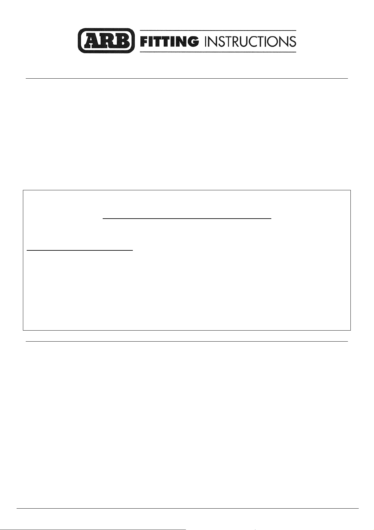
1. To remove the bumper bar from the vehicle
undo the 7 screws that hold the plastic guard
liner to the bumper bar on each side. Undo the
four nuts that hold the bumper to the
aluminum brackets and loosen the two nuts
located on the inside out board face.
Disconnect the fog lamp harness from both
lamps and with assistance pull the bumper bar
forward enough to disconnect the head lamp
washers.
2 Remove the aluminum chassis extension
brackets from both sides. Remove the
tubular cross brace and the recovery
bracket. Both are refitted at a later stage.
Undo the 5 screws that hold the plastic air
shield in place and with a small flat blade
screw driver remove the two yellow plugs
from the under side of the chassis rails.
3. Drill holes out to ½” through chassis rails and
tow hook.
4. Fit the new impact absorbers to both the LH &
RH chassis rails. Note that the smooth face
faces outwards with hole on the inside. Using
the ½” hardware supplied, bolt the RH
impact absorber into position. At this stage
only the two horizontal bolts are fitted, repeat
this on the LH side using the ½” hardware
supplied.
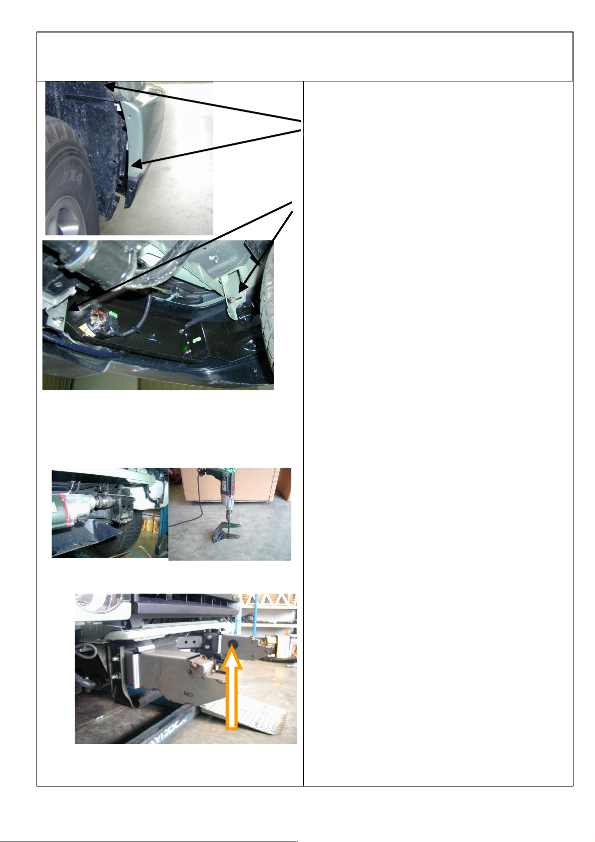
5. Once the impact absorbers are sitting
horizontal and at the same height tighten both
bolts. The holes in the impact absorber
bottom bracket should line up with the square
holes in the chassis. Before drilling the
vertical pinning bolts measure the distance
between the two out side edges of the impact
absorber – making sure the measurement is
no larger than 807 mm (loosen bolts and
adjust if necessary).
Page 4
13/6/08
Page 4 of 11
3786950
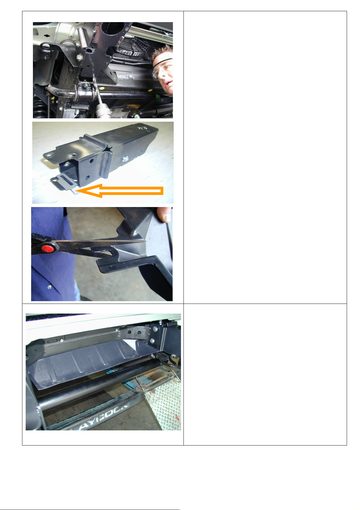
6. When drilling the vertical pinning bolt THE
DRILL MUST BE STRAIGHT IN BOTH
DIRECTIONS. Failure to do so will result in
damage to the radiator mounting system. Drill
out both holes and assemble using the long
M10 bolts and hardware supplied. From the
out board side of the chassis insert the chassis
packers between the under side of the chassis
and the impact absorber with the finger tab
facing downward. Repeat this on the LHS.
This picture shows how to fit chassis packer in
between chassis bracket and chassis rail.
Picture is of RHS of vehicle
7. The plastic air shield needs to be trimmed
before being replaced, cut the holes (located
on the edge tabs) into an open ended slot.
Place the shield back into its original position
and screw across the back edge in 3 locations.
The edge tabs are now pushed in on top of the
spacer, the tabs are retained when the vertical
bolts are done up between the chassis and the
chassis spacer.
Re – confirm the measurement between
the impact absorbers and tighten all of
the vertical bolts.
8. Remove the horizontal bolts only, as previously
described in step 3. Re – assemble but this time
the tubular cross brace and the original
recovery point are attached.
Note: the recovery bracket is located to the left
hand chassis rail.
Page 5

13/6/08
Page 5 of 11
3786950
9. Placing the original bumper bar face down
on a blanket remove all of the screws that hold
the painted outer section to the main bumper.
Using pliers remove the clip that holds the
washer nozzle in the bumper and take out the
nozzle (both sides). These are re-fitted into the
bar once the fog lamp and turn signal are
installed.
Using a small flat bladed screw driver disengage the locking tabs on both sides and
remove the cover, this will enable the fog lamp
to be un-screwed in three places and removed.
10. Fit the “u” nuts to the fog lamp bracket as
shown, the nylon washer fits between the
bracket and the lamp mounting foot
(located on the adjustment side) fit the fog
lamp with the screws provided.
Note:- The Left hand fog lamp is shown.
Insert the nylon plugs into the square holes
in the turn signal aperture, located on the
inside face of the bar. From the rear,
screw the turn signal assembly to the
bracket on the bar.
Re-fit the washer nozzle both sides once the
fog lamp & turn signal are fitted. The
washer retaining clip may need to be
flattened slightly to fit.
NYLON PLUG
Page 6

13/6/08
Page 6 of 11
3786950
IF NOT FITTING WINCH
11. Wrap rubber extrusion around winch cover.
12. Place washers over the winch cover fixing
holes located on the top middle face of the
bar.
13. Place the winch cover on top of the bar inline
with the mount holes.
Bolt together using the M6 button head
stainless steel screws and M6 nuts.
14. Fit buffers to bar using 6mm hardware.
IMPORTANT
1. Sahara Bumper has no large top hole
2. If fitting Sahara Bumper go to step 16
15. Fit the top tube through the hole in the top of
the buffer and secure from underneath using
M12 x 40mm bolt, spring washer and flat
washer.
NOTE This step for Sahara Bar only
Page 7

13/6/08
Page 7 of 11
3786950
TO FIT WINCH INTO BAR
16. If vehicle is to be fitted with a winch, follow
the next steps.
Handle is in normal position
17. Rotate handle 144° counter clockwise.
18. Stand winch upright and undo the capped
head screws and by lifting the gearbox only a
couple of millimetres, rotate the gearbox.
Once in position, refit all screws and tighten
firmly.
WARNING
Do not lift gear box more than a couple of
millimetres.
19. Drill out roller fairlead 25mm lower than
original hole using a 12mm drill bit.
NEW HOLES
Page 8

13/6/08
Page 8 of 11
3786950
20. Fit control box bracket to bar using 8mm
hardware.
21. Fit winch into bar using 1 1/2” x 3/8”
bolt on top holes and 1 ¾” x 3/8” bolt on the
lower holes plus 25mm large flat washers and
spring washers.
Cable spools from bottom of winch.
When fitting roller fairlead to bar,
remove circlips and push vertical
pins upward to move the vertical
rollers sideways to enable you to
place a socket to the bolt. When all
bolts are fitted replace vertical
pins and circlips.
Page 9

13/6/08
Page 9 of 11
3786950
22. Fit control box to bracket and connect all
power cables to winch motor as per warn
instructions.
23. Connect ground wire to winch tension bar.
24. Cable tie all cables together and keep clear of
sharp edges and all moving parts.
When bar is fitted to vehicle, fit both
power cables to battery and cable tie to
vehicle keeping clear of all moving parts.
25. With assistance lift the bar into position
and slide it over the two impact absorbers.
Once in position bolt up the bar in the 8
places using the M10 bolts & hardware
supplied, finger tight only at this stage.
Adjust the bar on the vehicle until a uniform
gap is achieved to the grille & headlamp
and guards. Once happy with the position of
the bar tighten all of the bolts.
The bar is then drilled and pined in its
final position using the M10 hardware
supplied as shown in the attached photo.
26.Re-connect the fog lamp harness and the
turn signal harness on both sides of the
vehicle, cable tie the wiring where
appropriate.
Ensure the turn signal & fog lamps are
working correctly.
Reconnect the head lamp washer tubes on
both sides.
Page 10

13/6/08
Page 10 of 11
3786950
.
27. Trim the plastic inner guard liners by
aligning with the bar and using the hole in the
wing as a guide, drill a 6 mm hole and secure
with the M6 hardware supplied
28. Fit number plate to number plate bracket
using 6mm hardware in this position.
Place double sided tape on rear of number
Plate to stop any vibration.
29. Fit number plate to bar using 6mm hardware
using the outer holes of number plate.
Place double sided tape on rear of number
Plate to stop any vibration.
Page 11

13/6/08
Page 11 of 11
3786950
 Loading...