

Page 1
Part Number:
Product
3915040/050 F/Kit 6172323
ARB SAHARA BAR
Description:
Suited to
TOYOTA LANDCRUISER 200 SERIES 2007 ON
vehicle/s:
3915040 NO HLC & 3915050 WITH HLC (SAHARA)
WARNING
REGARDING VEHICLES EQUIPPED WITH SRS AIRBAG;
When installed in accordance with these instructions, the front protection bar does not affect operation of
the SRS airbag.
ALSO, NOTE THE FOLLOWING:
♦
This product must be installed exactly as per these instructions using only the hardware supplied.
♦
In the event of damage to any bull bar component, contact your nearest authorised ARB stockist.
Repairs or modifications to the impact absorption system must not be attempted.
♦ Do not use this product for any vehicle make or model, other than those specified by ARB.
♦
Do not remove labels from this bull bar.
♦
This product or its fixing must not be modified in any way.
♦
The installation of this product may require the use of specialized tools and/or techniques
♦
It is recommended that this product is only installed by trained personnel
♦
These instructions are correct as at the publication date. ARB Corporation Ltd. cannot be held
responsible for the impact of any changes subsequently made by the vehicle manufacturer
♦
During installation, it is the duty of the installer to check correct operation/clearances of all
components
♦ Work safely at all times
♦
Unless otherwise instructed, tighten fasteners to specified torque
ARB 4x4 ACCESSORIES
42-44 Garden St Tel: +61 (3) 9761 6622
Kilsyth, Victoria Fax: +61 (3) 9761 6807
AUSTRALIA 3137
Australian enquiries sales@arb.com.au
North & South American enquiries sales@arbusa.com
Other international enquiries exports@arb.com.au
Corporate Head Office
www.arb.com.au
Last Rev Date: 28 OCTOBER 2008 Page 1 of 22 Fitting instructions# 3781218
Copyright © 2005 by ARB Corporation Limited. All rights reserved, this document must not be reproduced without the express authority of ARB Corporation Ltd
Page 2

GENERAL CARE AND MAINTENANCE
By choosing an ARB Bar, you have bought a product that is one of the most sought after 4WD products
in the world. Your bar is a properly engineered, reliable, quality accessory that represents excellent
value. To keep your bar in original condition it is important to care and maintain it following these
recommendations:
Prior to exposure to the weather your bar should be treated to a Canuba based polish on all exposed
surfaces. It is recommended that this is performed on a six monthly basis or following exposure to
salt, mud, sand or other contaminants.
As part of any Pre Trip Preparation, or on an annual basis, it is recommended that a thorough visual
inspection of the bar is carried out, making sure that all bolts and other components are torqued to
the correct specification. Also check that all wiring sheaths, connectors, and fittings are free of
damage. Replace any components as necessary. This service can be performed by your local
authorized ARB Stockist.
FITTING REQUIREMENTS
REQUIRED TOOLS FOR FITMENT OF PRODUCT:
Metric socket and spanner sets 8-25mm range
Screwdrivers, Philips and Flat blade Power Jigsaw with blade for plastic cutting
Short Body Power Drill 13mm (1/2”) capacity Dia 7.0mm (5/16”) and 10.5mm (25/64”) drill bits
Tin snips Marking pen
Half round file Soft Hammer
Metric hex key set Loctite© 262 or equiv.
Wide masking tape Stanley knife
Small Spirit Level Tape Measure & 2 x 300mm rulers
If fitting parking sensors: Dia 22.0 (7/8”) hole saw Paint black fast drying
External Circlip pliers
HAVE AVAILABLE THESE SAFETY ITEMS WHEN FITTING PRODUCT
:
Protective eyewear
NOTE: ‘WARNING’ notes in the fitting procedure relate to OHS situations, where to avoid a
potentially hazardous situation it is suggested that protective safety gear be worn or a safe work
procedure be employed. If these notes and warnings are not heeded, injury may result.
Hearing protection
FASTENER TORQUE SETTINGS:
SIZE Torque Nm Torque lbft
M6 9Nm 7lbft
M8 22Nm 16lbft
M10 44Nm 32lbft
M12 77Nm 57lbft
Last Rev Date: 28 OCTOBER 2008 Page 2 of 22 Fitting instructions# 3781218
Copyright © 2005 by ARB Corporation Limited. All rights reserved, this document must not be reproduced without the express authority of ARB Corporation Ltd
Page 3

APPLICATION. PART NO. QTY DESCRIPTION
Mount Brackets To Chassis
Brace Assembly
Bull Bar To Mount Bracket Assy
Stone Tray to Bull Bar
Winch To Bull Bar
Number Plate To Bull Bar
If Not Fitting Winch
Wing Inner Panels
Buffer fasteners
Lights
PARTS LISTING
Bracket Mount RHS
3757602R
3757602L
6151429
6151428
6151396
5846400
4681274
6151357
6151321
6151357
6151321
6151255
6151189
4581049
4581050
6522683
6151300
6151213
4581082
4581287
6151270
4721518
3756499
6151234
4581045
4581047
6151132
180302
EG50
6151074
6821189
6151384
6781408
6522695
6191013
6151256
4581304
6151128
6522685R
6522685L
6151300
6151213
4581082
4581287
6151234
4581045
4581047
6151132
6151128 12 Nut M6 Flanged
3163015
6821151R
6821151L
6821152
180701
180302
1
1
2
2
2
2
1
7
7
2
2
6
6
12
6
1
4
4
6
6
2
2
1
2
2
2
2
8
2
2
2
2
1
1
1
2
4
2
1
1
10
10
10
10
2
2
2
2
1PR
1
1
2
6
6
Bracket Mount LHS
Chassis Stud M12 x 265 x1.75
Flange Nut M12 x 1.75
Nut Clevis
Packer M12 x 8mm
Brace
SEMS Bolt M10 x 1.5 x 30mm
Nut Flanged M10 x 1.5
SEMS Bolt M10 x 1.5 x 30mm
Nut Flanged M10 x 1.5
Bolt M12 x 1.75 x 40mm
Nut M12 x 1.75
Washer Flat M12
Washer Spring M12
Stone Tray
Nut Cage M6
Bolt M6 x 20mm
Washer Flat M6 x 16 x 3
Washer Spring M6
Bolt M6 x 40
Spacer Tube 18mm
Bracket Control Box Univ.
Bolt M8 x 25
Washer Flat M8 BZ
Washer Spring M8 BZ
Nut M8 Flanged
Cable Tie
Grommet Dia 50mm
Bolt 3/8 x 1 3/4
Grommet round
Screw self tapping pan head
Tape double sided
Winch Panel
Extrusion
Screw M6 x 15 st stl Dome Head
Washer M6 St Stl
Nut Flanged M6
Panel Inner Wing RH
Panel Inner Wing LH
Nut Caged M6
Bolt M6 x 20 Blk
Washer Flat M6 Blk
Washer Spring M6 Blk
Bolt M8
Washer Flat M8
Washer Spring M8
Nut M8 Flanged
Light Surround Set
Indicator
Indicator
Loom
Scotch Locks
Cable Ties
Last Rev Date: 28 OCTOBER 2008 Page 3 of 22 Fitting instructions# 3781218
Copyright © 2005 by ARB Corporation Limited. All rights reserved, this document must not be reproduced without the express authority of ARB Corporation Ltd
Page 4

Trim Pinch Weld
6191020
3786342
EG50
Miscellaneous
6151415
4581040
4581048
5868356
2
Template Bumper Cutting
1
Grommet Dia 50mm
2
Cap Screw M10 x 40 ZP
4
Washer Flat M10
4
Washer Spring M10
4
Packer
3
OPTIONAL LIGHT SETS TO SUIT THIS PRODUCT:
♦ FOG LAMP SET P# 6821201 ADD GXL ONLY P#MD02 LOOM KIT, P#180209 SWITCH AND
P#180215 SWITCH CAP FOR FOGS
♦
UP TO IPF 900 SERIES FOG OR DRIVING LIGHT SETS
♦ IPF 840 FYS FOG LIGHTS CAN BE FITTED TO LOWER PAN AREA
AVAILABLE BUFFER/FRAME SETS:
♦
5100140 BUFFER SET ONLY WITH FRAME HOLE
♦
5100150 BUFFER SET ONLY BLANK
♦
5115010 FRAME ASSEMBLY (NOTE: FASTENERS ARE WITH THIS BAR KIT)
Last Rev Date: 28 OCTOBER 2008 Page 4 of 22 Fitting instructions# 3781218
Copyright © 2005 by ARB Corporation Limited. All rights reserved, this document must not be reproduced without the express authority of ARB Corporation Ltd
Page 5
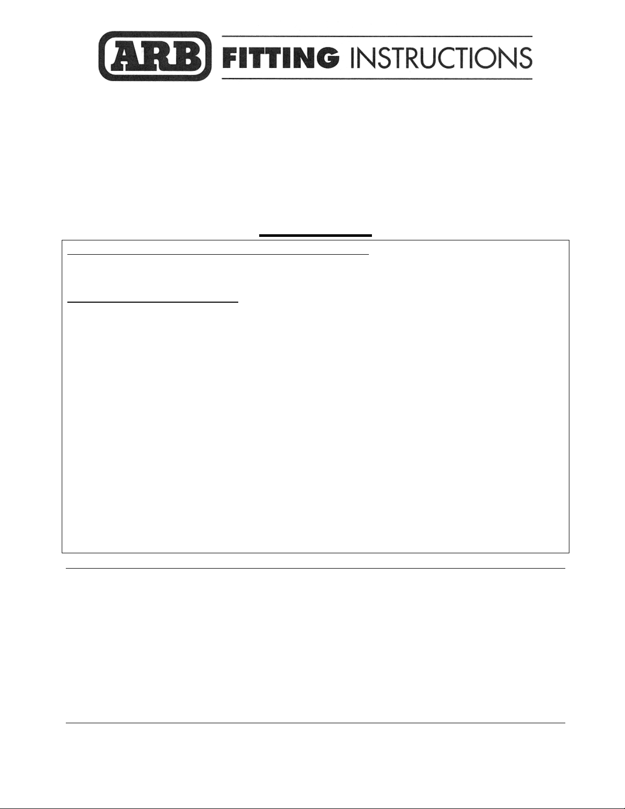
REMOVAL OF BUMPER
1. Remove number plate
2. Remove number plate mount bracket
3. Remove inner guard bumper retaining
screws three per side using M4 hex key
4. Remove lower trim panel sets each side
which attach to bumper and engine
protective plate area then set aside, they
will not be reused.
Last Rev Date: 28 OCTOBER 2008 Page 5 of 22 Fitting instructions# 3781218
Copyright © 2005 by ARB Corporation Limited. All rights reserved, this document must not be reproduced without the express authority of ARB Corporation Ltd
Page 6
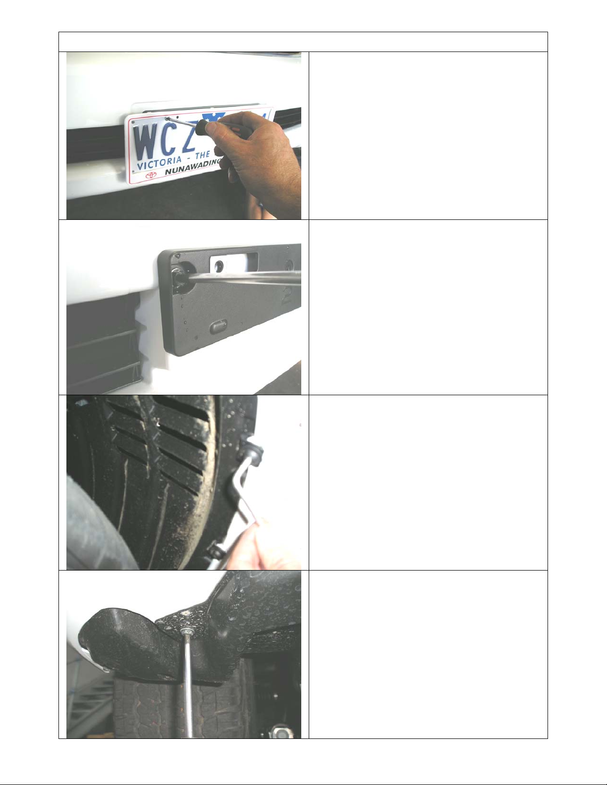
REMOVAL OF BUMPER
5. When removing lower trim panels, a
plastic nut located on each side will need
to be prized open with a small flat blade
screwdriver to assist removal.
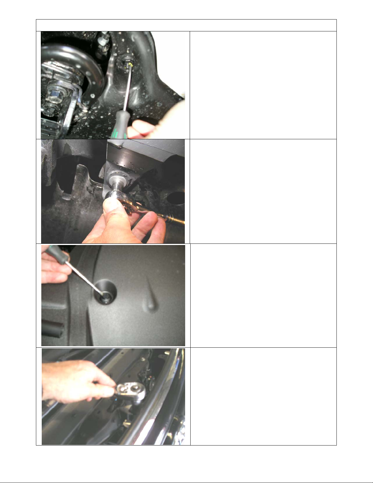
6. Remove lower bumper retaining screws.
7. Remove plastic engine bay cover above
grille area and set aside. Prise open
plastic plugs with small flat blade
screwdriver or similar as shown.
8. Remove 3 x retaining screws from top of
grille
Last Rev Date: 28 OCTOBER 2008 Page 6 of 22 Fitting instructions# 3781218
Copyright © 2005 by ARB Corporation Limited. All rights reserved, this document must not be reproduced without the express authority of ARB Corporation Ltd
Page 7
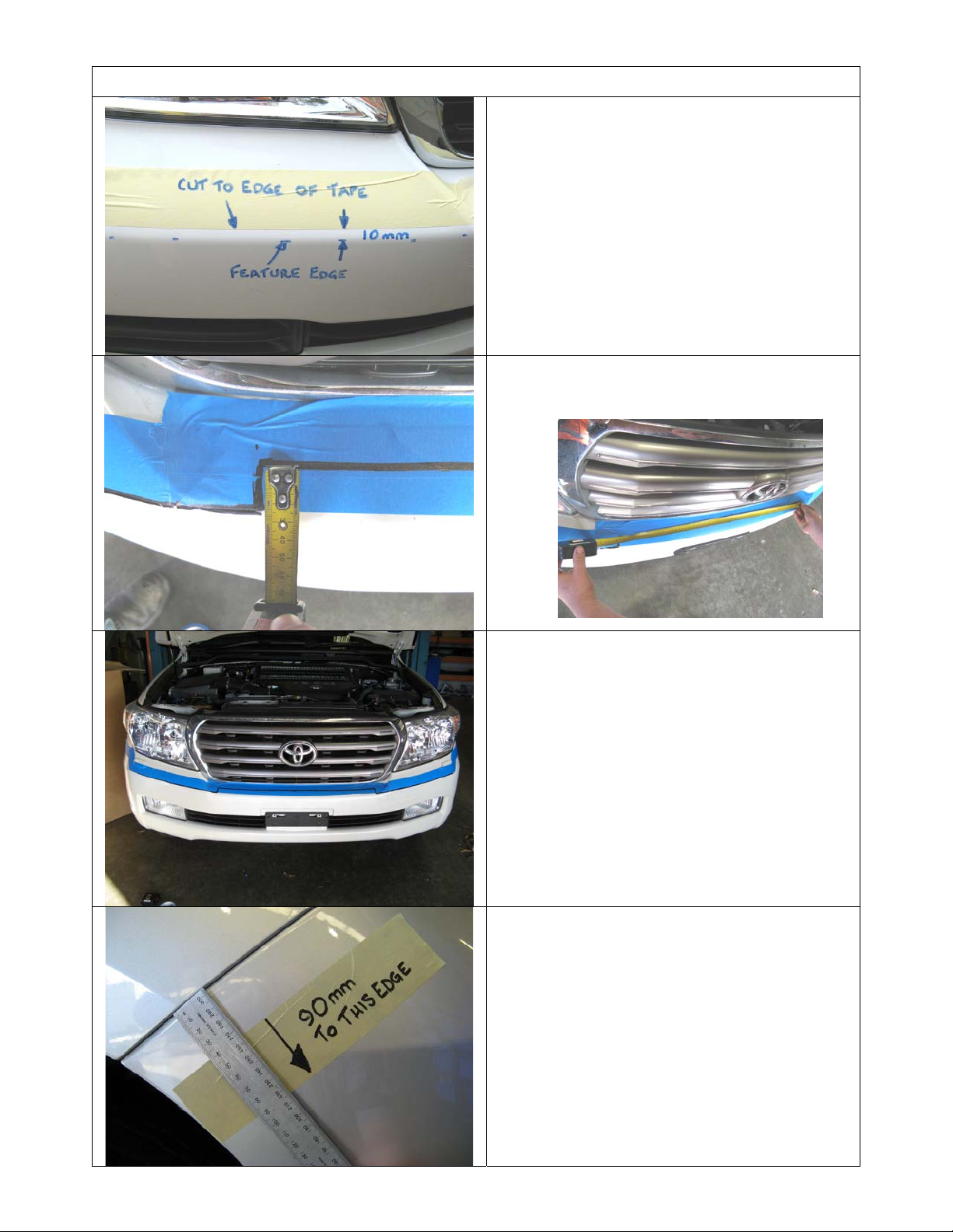
MASKING BUMPER FOR TRIMMING
9. Apply wide masking tape edge, carefully
aligning 10mm above bumper feature
line as shown. Keep the same line level
through the centre section of the buffer
as shown
Hint: Using a marking pen, run a line or
dashed lines along the feature line on the
bumper to assist in measuring the 10mm
offset for the tape application.
10. Mark out centre cut area of bumper as
shown, 740mm wide x 30mm back from
feature edge.
11. View of masking tape and cut line
across bumper for reference.
12. Apply approx.200mm of masking tape
with edge exactly 90mm from angled
bumper end as shown.
Last Rev Date: 28 OCTOBER 2008 Page 7 of 22 Fitting instructions# 3781218
Copyright © 2005 by ARB Corporation Limited. All rights reserved, this document must not be reproduced without the express authority of ARB Corporation Ltd
Page 8

MASKING BUMPER FOR TRIMMING
13. Cut A3 paper template along identified
cutting line.
NOTE: There is a scale on the sheet to
confirm that the template is 1:1 scale, this
is critical.
14. Apply template to outer corner of RHS
bumper as shown aligning accurately to
features such as the lower line of
headlamp and end of bumper. Tape in
position
Cutting line
15. Transfer cutting line to bumper
16. Apply masking tape aligning edge to
marked cut line as shown
17. Reverse template and apply to LHS of
bumper and follow same steps as RHS.
18. The bumper is now marked out for
cutting.
Last Rev Date: 28 OCTOBER 2008 Page 8 of 22 Fitting instructions# 3781218
Copyright © 2005 by ARB Corporation Limited. All rights reserved, this document must not be reproduced without the express authority of ARB Corporation Ltd
Page 9

REMOVAL OF BUMPER
19. Release top of grille. It is retained by 2 x
push in spring clips, located at the outer
top sections below the bolt position.
Hint: You can use a small flat blade
screwdriver to aid in pushing in spring.
20. Pull outer returns of bumper outwards
and out of retaining clips.
21. If required push bumper down
immediately below headlamp to gain
access with a small flat blade screwdriver
and release holding tab.
NOTE: Take care not to damage painted
edge of bumper
22. Remove plastic plugs securing upper
bumper tabs to cross member.
23. If headlight washer system is fitted
disconnect the main line from the vehicle
to the bumper circuit and clamp/crimp it to
prevent washer fluid from leaking out
24. If factory fog lights are fitted, disconnect
the fog light harness from the vehicle by
opening the white flip over clip on the
connector and releasing the loom plug..
Last Rev Date: 28 OCTOBER 2008 Page 9 of 22 Fitting instructions# 3781218
Copyright © 2005 by ARB Corporation Limited. All rights reserved, this document must not be reproduced without the express authority of ARB Corporation Ltd
Page 10

g
REMOVAL OF BUMPER Cont.
25. Bumper can now be carefully removed
and placed on a clean, non abrasive, soft
surface face down. It is best to do this
with the help of another person.
NOTE: As bumper is being removed, check
that all
wiring looms etc are disconnected
26. Remove grille from bumper cover by
releasing plastic tabs as shown
27. Remove fog light brackets and fog lights
if fitted and set aside, these will not be
reused
28. Remove headlight washer circuit if fitted
and retain for reuse.
29. Remove fog light loom if fitted for reuse
Cutting edge
30. Place bumper face up on a bench or
similar so there is sufficient access for the
cutting operation
31. Using a jigsaw, carefully cut along the
edge of the masking tape.
32. Remove burrs from the cut edge of the
bumper, then set aside on the soft non
abrasive surface.
Warning: Cutting
operations can result in
flying debris, safety glasses
should be worn. Work
safely; keep fingers clear of
cuttin
blade.
Cutting line
Last Rev Date: 28 OCTOBER 2008 Page 10 of 22 Fitting instructions# 3781218
Copyright © 2005 by ARB Corporation Limited. All rights reserved, this document must not be reproduced without the express authority of ARB Corporation Ltd
Page 11

PREPARATION FOR MOUNT BRACKETS
33. Remove foam absorber bar and set
aside, this will not be reused
34. Remove crash bar then beam mount
brackets and set aside, retain only M10
flange nuts for reuse.
35. Remove tow hooks and set aside, these
will be reused.
Mark line 60mm
from front face,
other lines as
indicated
36. Mark the lower section of the air scoop
for the power steering radiator as shown.
This is for trimming to clear the mount
brackets.
Note: The 60 mm line from front as indicated
goes right over the top of the scoop and down
the other side, then steps back in the same at
70mm from top, then back to 15mm and down
as shown this side.
37. Remove scoop and cut using jigsaw or
similar and remove burrs.
Warning: Cutting
operations can result in
flying debris, safety glasses
should be worn.
Last Rev Date: 28 OCTOBER 2008 Page 11 of 22 Fitting instructions# 3781218
Copyright © 2005 by ARB Corporation Limited. All rights reserved, this document must not be reproduced without the express authority of ARB Corporation Ltd
Page 12

PREPARATION FOR MOUNT BRACKETS
38. Refit to vehicle, it should now look like
this.
39. Mark out and trim the air deflector on the
LHS of the vehicle using a pair of tin snips
or similar.
Hint: You can do this on the vehicle as shown
below.
40. Fit the cut bumper and secure.
41. Fit the grille
42. Fit pinch weld to each end of the bumper
as shown
43. Secure the wing return with one of the
original dome head screws each side.
Last Rev Date: 28 OCTOBER 2008 Page 12 of 22 Fitting instructions# 3781218
Copyright © 2005 by ARB Corporation Limited. All rights reserved, this document must not be reproduced without the express authority of ARB Corporation Ltd
Page 13

PREPARATION OF BULL BAR
44. Fit 2 x large rubber grommets to holes in
uprights inside the upper area of the bull
bar.
45. If fitting fog lamps, factory loom can be
reused and routed through the grommets
in uprights and along inside the lower lip
of the top pan.
46. If headlight cleaner circuit is to be refitted,
run hosing along the underside of the
grille cross member, cable tie in position
as shown
IF FITTING WINCH
ORIGINAL
POSITION
47. Fit large grommets to holes in top pan
48. Fit control box bracket to control box
studs as shown.
Picture also shows
routing of leads through grommets in pan.
49. Using M8 fasteners fit control box
mounting bracket to pan
50. Prepare winch for fitting by undoing the
cap screws on the gearbox end.
51. Then rotate the end cap and gearbox in a
counter clockwise direction 144° ( four
hole pitches) while looking down at the
gearbox, as shown (for 12000lb winches
rotate clockwise 144°)
52. Tighten the cap screws ensuring the
gearbox handle operates freely.
NEW
POSITION
53. Rotate the motor end 90° clockwise (elec.
terminals will be up, see step 58)
NOTE: Be careful not to lift the gearbox more
than a few millimetres. Before doing up cap
screws, ensure that the flange faces engage
properly and gaskets are not damaged.
Last Rev Date: 28 OCTOBER 2008 Page 13 of 22 Fitting instructions# 3781218
Copyright © 2005 by ARB Corporation Limited. All rights reserved, this document must not be reproduced without the express authority of ARB Corporation Ltd
Page 14

PREPARATION OF BULL BAR
54. Position the winch with the mount face
facing upward on an adjustable table or
similar and with the assistance of another
person lower the bulbar over the winch.
The winch handle should be in the LHS of
the bull bar for all winches except 12000lb
winch is on the opposite side. The cable
must spool off the bottom of the winch.
NOTE: Also follow the installation
instructions in the Warn winch handbook
accompanying the winch.
55. Fit the roller fair lead, pull only the end of
the cable through and adjust the position
of winch then bolt up securely. Use the 1
½” long bolts in the top and 1 ¾”in the
lower set through the RFL.
Hint: To increase access to mount bolts in front of
roller fairlead, remove circlips from bottom of each
vertical roller shaft, push shaft up so roller can be
dislodged sideways. Do up bolts in fairlead and
winch, then refit circlip.
Cut off or bend
back at 90° this
entire forward
section at this line
56. With the aid of another person, turn the
bull bar over so that the back of the bar is
accessible.
57. Connect up the wires to the winch.
NOTE: Refer to the Warn winch handbook for
wiring instructions to vehicle.
If fitting 12000LB winch only
58. Relieve by cutting off or bending back at
90° a section of the cross member
support bracket as shown to clear winch
tie rod.
Last Rev Date: 28 OCTOBER 2008 Page 14 of 22 Fitting instructions# 3781218
Copyright © 2005 by ARB Corporation Limited. All rights reserved, this document must not be reproduced without the express authority of ARB Corporation Ltd
Page 15

PREPARATION OF BULL BAR
59. Fit 4 x M6 cage nuts to bottom inside
face of lower pan in square holes as
shown.
Hint: A small flat blade screwdriver may help to
press nut cage flanges into hole.
Sensors fit on
these outer
corners, 90mm
down from top
face
Hole saw Dia 22.0 (7/8”)
Warning: Cutting operations
can result in flying debris, safety
glasses should be worn.
60. If parking sensors are to be fitted, mark
out the hole positions, located in the
middle of the large corner radius of the
wings and 90mm down from the top face.
(Similar position to original bumper)
Hint: Use two rules across flat faces to find
mid point of radius
61. Once Dia 22 (7/8”) hole is drilled and
fully deburred, check that the hole size is
actually Dia 22.0 – 22.8mm, better if on
larger side.
Trial fit sleeve and sensor.
62. Once checked use some fast drying
primer paint to seal bare edges.
IF FITTING FRAME AND BUFFERS
63. If fitting centre frame, loose fit the pair of
buffers with holes P#3163017R&L by
sliding up onto frame, noting that the
buffers are handed.
64. Mount frame and secure with 2 sets of
M10 x 40 cap screws and washers per
side as shown, noting that the frame leans
rearwards once on vehicle
65. Slide buffers down over frame until they
sit correctly onto bull bar and tube profile.
66. Fasten buffers with 6 x M6 flange nuts
per buffer once buffers are carefully
pushed home against the profile of the
bull bar and centralised over tube, be
careful not to over tighten the flange nuts
as damage to buffer can result.
Last Rev Date: 28 OCTOBER 2008 Page 15 of 22 Fitting instructions# 3781218
Copyright © 2005 by ARB Corporation Limited. All rights reserved, this document must not be reproduced without the express authority of ARB Corporation Ltd
Page 16

IF FITTING BUFFERS ONLY
67. If fitting buffers only, fit the
P#31631016R&L buffers, noting that they
are handed and ref the part numbers on
the buffers
68. Fasten with 6 x M6 flange nuts per buffer
once buffers are carefully pushed home
against the profile of the bull bar, be
careful not to over tighten the flange nuts
as damage to buffer can result.
IF NOT FITTING WINCH
69. Fit rubber extrusion to cover panel as
shown starting and finishing at the centre
of the large radius side which is the back
then trim to length
Applying trim rubber, note the join is at
middle of the rear of the plate or long side
The narrower section of the plate is to front
of bull bar
70. Fit the panel to the top of the bull bar as
shown using M6 pan head stainless steel
screws, M6 flat st stl washers and M6
flange nuts. Use 2 x M6 st stl flat washers
as packers in between the panel and the
top of the bull bar to stop the panel from
dishing.
Last Rev Date: 28 OCTOBER 2008 Page 16 of 22 Fitting instructions# 3781218
Copyright © 2005 by ARB Corporation Limited. All rights reserved, this document must not be reproduced without the express authority of ARB Corporation Ltd
Page 17

FITTING MOUNT BRACKETS
Packers are supplied to compensate for
body to chassis variation if required
71. Insert clevis nut into rectangular hole in
the inboard face of chassis, ensuring the
threaded end is inserted first.
The nut when fitted correctly should fit
square and locate into the chassis rail.
72. Install the clevis stud by fitting 2 nuts to
the end of the stud and tightening until
thread bottoms out.
73. Remove nuts and repeat for the LHS.
74. Loosely fit the mounting brackets to the
chassis securing with the 8mm packers
and flange nuts.
75. Secure using existing OE M10 flange
but do not do up tight
nuts,
.
76. Tap the outer flange of the mount
brackets until they are hard up against the
tow hook mount area. Nip up the lowest
outboard nut on each bracket. Brackets
should be about 935mm apart
Last Rev Date: 28 OCTOBER 2008 Page 17 of 22 Fitting instructions# 3781218
Copyright © 2005 by ARB Corporation Limited. All rights reserved, this document must not be reproduced without the express authority of ARB Corporation Ltd
Page 18

FITTING BULL BAR TO VEHICLE
77. With the aid of a lift table or one or more
assistants carefully and safely lift, position
and bolt the bull bar to the mounts using 6
x M12 bolts, large flat washers and spring
washers. Centralise the bar to the front of
the vehicle and adjust height.
78. Fit the cross brace to underside of lower
pan and on top of gussets in mount
brackets. Use M10 x 30mm SEMS bolt
and washer sets, flange nuts
do up tight.
79. Adjust the bar height leaving
approximately 15mm gap between top of
wing angled face and the pinch weld on
bumper.
80. Tighten bar mount M12 bolts
but do not
15mm gap
81. Tighten M10 flange nuts to chassis studs
to 56Nm.
82. Then tighten up the long M12 chassis
studs, ensuring that the clevis nut is
positioned correctly over the hole in the
chassis.
83. Tighten brace bolts.
84. Remove each tow hook bolt in turn, apply
loctite © to threads and tighten up.
85. Using the M10 pilot holes in mount
brackets (located up 175mm from bottom
face of bar), drill pinning hole through
uprights on bull bar. Access is through
the fog light hole in wing. Fit M10 screw,
washer set and flange nut and do up tight.
Warning: Drilling operations can result in
flying metal debris, safety glasses should be
Last Rev Date: 28 OCTOBER 2008 Page 18 of 22 Fitting instructions# 3781218
Copyright © 2005 by ARB Corporation Limited. All rights reserved, this document must not be reproduced without the express authority of ARB Corporation Ltd
Page 19

FITTING BULL BAR TO VEHICLE
86. If headlight cleaner system to be fitted,
reconnect circuit at main joint to vehicle
and also hoses to tails of spray heads
87. Remove and discard screws and speed
nuts on supplied indicators.
88. Using the 25mm long pan head screws in
the light surround fitting kit, fit indicators to
light surrounds, note that the indicators
are handed and drain holes must be on
the lowest edge.
NOTE: These indicators may also be fitted
once the fog light surround is fitted into the
wing for ease of access to the clamp screws,
after step 93.
89. If fitting fog lamps, refer to instructions
supplied with kit.
Fog lamp wiring to factory loom shown for
reference.
90. Fit insert assemblies into the wings as
shown
91. Fit the 4 x clamps to secure light
assembly in position.
HINT: You can loose fit the top two screw
and clamp sets before loading the assembly
into the wing to make fit up easier.
Last Rev Date: 28 OCTOBER 2008 Page 19 of 22 Fitting instructions# 3781218
Copyright © 2005 by ARB Corporation Limited. All rights reserved, this document must not be reproduced without the express authority of ARB Corporation Ltd
Page 20

FITTING BULL BAR TO VEHICLE
92. Wire up indicators and parking lamps.
Running
lamp wiring
Indicator
lamp wiring
93. Connect red wire from supplied loom to
green wire from running (parker) lamp.
Connect black wire from supplied loom to
green/yellow indicator wire. Connect
green loom wire to white/black indicator
wire.
94. Use supplied scotch locks for the
electrical connections then secure wiring
with cable ties when complete.
HINT: Temporarily undo the battery clamps and
move batteries sideways to gain better access.
95. Wire up P# 6821201 ARB fog lamps if
fitted.
NOTE: For GXL use ARB Loom MD02 plus
switch, for VX and Sahara no extra loom or
switching is required. Supplied tails can be joined
to OE loom which is run through bull bar.
96. If parking sensors to be fitted, insert
sleeves first noting that they must be in
the same orientation as in the original
bumper (tab to top RHS down on LHS).
Check that
sensor fits
flush
Spacer tube
M6 thread in
vehicle tray
97. Fit sensors checking that they are not too
tight, otherwise correct operation may be
affected (if tight check hole size and
rectify as necessary)
98. Connect to main loom and cable tie wiring
securely
99. Fit stone tray using 4 x M6 bolts and
washer sets at front under bull bar and 2 x
M6 x 40 bolts, washers and 18mm long
tube spacers at two locations into existing
sump guard front section as shown.
100. Fit off winch hook.
Last Rev Date: 28 OCTOBER 2008 Page 20 of 22 Fitting instructions# 3781218
Copyright © 2005 by ARB Corporation Limited. All rights reserved, this document must not be reproduced without the express authority of ARB Corporation Ltd
Page 21

p
FITTING BULL BAR TO VEHICLE
Split horizontal
NOTE: Number plate sits above RFL opening
in pan when winch fitted, when no winch ,
number plate covers RFL opening in lower
Fit cage nuts to
inside faces
FITTING NUMBER PLATE
101. If winch fitted, apply double sided tape
strip to top back of number plate. If winch
not fitted, no adhesive strip is required.
102. Fit grommets to slots, with split horizontal
as shown
103. Fit number plate using supplied pan head
screws into grommets.
104. Tuck fender liner tab into wing return, trim
if necessary.
105. Fit 5 x M6 cage nuts to each wing splash
panel as shown on inside faces.
Note: LHS shown with 3 of 5 cage nuts inserted.
106. Fit panels up inside wings, secure using
M6 x 20 black bolts and washer sets. Fix
flange on panel to side of main mount
bracket using M8 bolt set.
Trim this
edge flush
with face of
anel
107. Mark out and drill 2 x Dia 7.0 mm holes in
each fender liner for securing to the
splash panel flange.
Hint: Scribe a line on the liner parallel to the
splash panel, measure and mark the position of
the required holes up from the marked line.
108. Use M6 x 20 black bolts and washer sets
to secure the fender liner to the panels.
109. Trim the fender liner end flush with the
splash panel face as shown.
Warning: Drilling operations can
result in flying debris, safety
glasses should be worn.
Last Rev Date: 28 OCTOBER 2008 Page 21 of 22 Fitting instructions# 3781218
Copyright © 2005 by ARB Corporation Limited. All rights reserved, this document must not be reproduced without the express authority of ARB Corporation Ltd
Page 22

NOTE:
♦
♦
♦
♦
♦
Check wiring connections to fitted lights and winch.
Check operation of winch and all lights.
Check operation of headlight washers if fitted
Check operation of parking sensors if fitted
IMPORTANT: Check that all piping and wiring is clear of sharp edges and pinch
points. Adjust any piping to clear the bull bar or mounts by a minimum of 15mm.
FINAL PRODUCT ON VEHICLE
Last Rev Date: 28 OCTOBER 2008 Page 22 of 22 Fitting instructions# 3781218
Copyright © 2005 by ARB Corporation Limited. All rights reserved, this document must not be reproduced without the express authority of ARB Corporation Ltd
 Loading...