

Aprilaire 8244 Installation And Operation Manual
Thermostat
Model 8244 Installation and Operation Manual
Non-Programmable Thermostat
Failure to follow and read all instructions carefully before installing or operating this control could cause personal
injury and/or property damage. If you have any questions, please call Research Products Corporation at (800) 334-6011.
PREPARATIONS
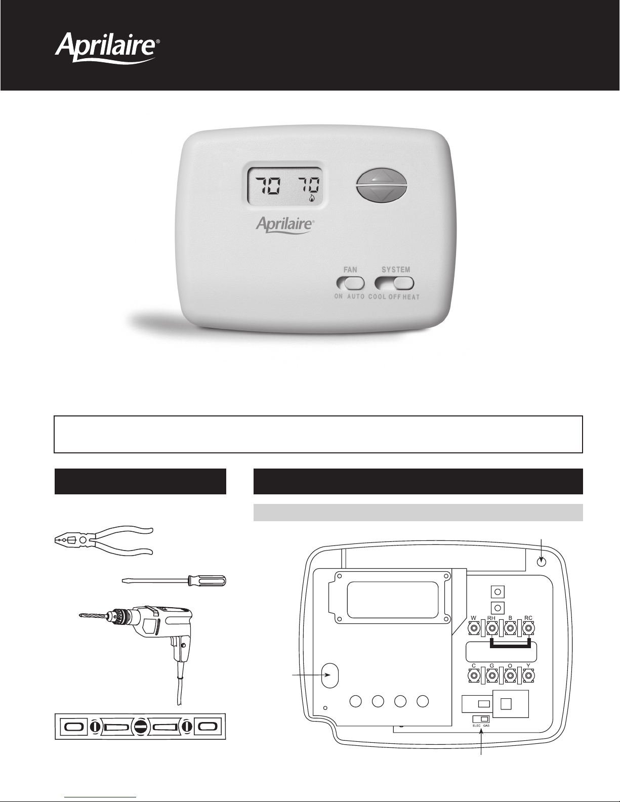
Assemble tools required as shown below.
Wire cutter/stripper
Flat blade
screwdriver
Electric or cordless
drill with 3/16 inch
drill bit, if needed.
THERMOSTAT DETAILS
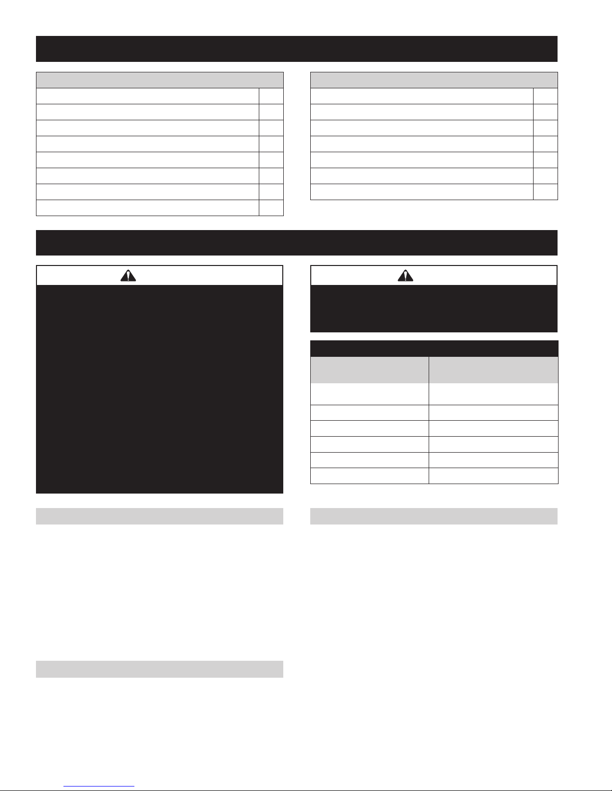
FIGURE 1 – Thermostat Base
Mounting hole
Mounting
hole
Level
Electric/Gas Switch
THERMOSTAT APPLICATIONS
Description
Standard Heat Only Gas or Oil Fired Systems (24 volt)* Yes
Electronic Ignition Heat Only Two Wire Systems (24 volt)* Yes
Electronic Ignition Heat Only Gas or Oil Fired Systems (24 volt)* Yes
Standard Heat/Cool Systems (24 volt)* Yes
Heat/Cool Systems Electric Heat (24 volt)* Yes
Heat Only Electric Heat Systems (24 volt)* Yes
Cool Only Systems (24 volt)* Yes
Heat Pump Systems (No Aux or Emergency Heat)* Yes
MOUNTING AND WIRING
WARNING
120 volts may cause serious injury from electrical
shock. Disconnect electrical power to the furnace & air
conditioner before starting installation. This thermostat
is not a 120 volt (line voltage) device.
Improper installation may cause serious injury from electrical
shock. This product must be installed by a qualifi ed
heating & air conditioning contractor in accordance with
NEC Standards and applicable local and state codes.
Do not use on circuits exceeding specifi ed voltage.
Higher voltage will damage control and could cause
shock or fi re hazard.
Do not short out terminals on gas valve or primary control
to test. Short or incorrect wiring will damage thermostat
and could cause personal injury and/or property damage.
Thermostat installation and all components of the system
shall conform to Class II circuits per NEC code.
Description
Hot Water Zone Heat Only Systems No
Hot Water Zone Heat Only (Three Wire) Systems No
Line Voltage Heating or Baseboard 110/240 Volt Systems No
Millivolt Systems Floor or Wall Furnaces No
12 VDC Mobile Home Application No
Multi-stage Systems No
Systems Exceeding 30VAC, 1.5 Amp No
*Requires common wire for 24VAC at the thermostat
CAUTION
Take care when securing and routing wires so they do
not short to adjacent terminals or rear of thermostat.
Personal injury and/or property damage may occur.
Terminal Cross Reference Chart
New Thermostat
Terminal Designation
RH 4 RH M
RC RRV–
GGGFG
WWWHW
Y YYCY
C CCXC
*Factory installed jumper wire between the RH and RC terminals must remain in place.
Other Manufacturers’
Terminal Designation
*
R
ELECTRIC HEAT OR SINGLE-STAGE HEAT PUMP SYSTEMS
This thermostat is confi gured from the factory to operate a heat/cool,
fossil fuel (gas, oil, etc.), forced air system. It is confi gured correctly
for any system that DOES NOT require the thermostat to energize
the fan on a call for heat. If your system is an electric or heat-pump
system that REQUIRES the thermostat to turn on the fan on a call for
heat, locate the ELECTRIC/GAS switch (see Figure 1) and switch it
to the ELECTRIC position. This will allow the thermostat to energize
the fan immediately on a call for heat. If you are unsure if the
heating/cooling system requires the thermostat to control the fan,
contact a qualifi ed heating and air conditioning service person.
HYDRONIC (HOT WATER OR STEAM) HEATING SYSTEMS
This thermostat is set to operate properly with a forced-air heating
system. If you have a hydronic heating system (a system that heats
with hot water or steam), you must set the thermostat to operate
properly with your system by changing the fi rst option in the
confi guration menu to SL (see Confi guration Menu, page 5).
2
CHOOSE A LOCATION TO MOUNT THE THERMOSTAT
MOUNT THE THERMOSTAT…
• Approximately 5 feet above the fl oor. Refer to local codes for
compliance with the Americans with Disabilities Act (ADA).
• On an interior wall in a frequently occupied space where the
temperature is most representative of the zone being controlled
by the thermostat.
• At least 18 inches away from an outside wall.
DO NOT MOUNT THE THERMOSTAT…
• Behind doors, in corners or other dead air spaces.
• In direct sunlight, near lamps or other sources of heat.
• On an outside wall or any wall exposed to an unconditioned space
(a garage for example).
• In the airfl ow path of a supply register, in stairways or near
outside doors.
• On a wall where concealed pipes or ductwork will affect the
thermostat temperature accuracy.
• Near sources of electrical interference, such as arcing switch contacts.
 Loading...