

Aprilaire 8191, 8192 Installation Manual
Model 8191 & 8192 Ventilator with Dehumidification
Installation and Operating Instructions
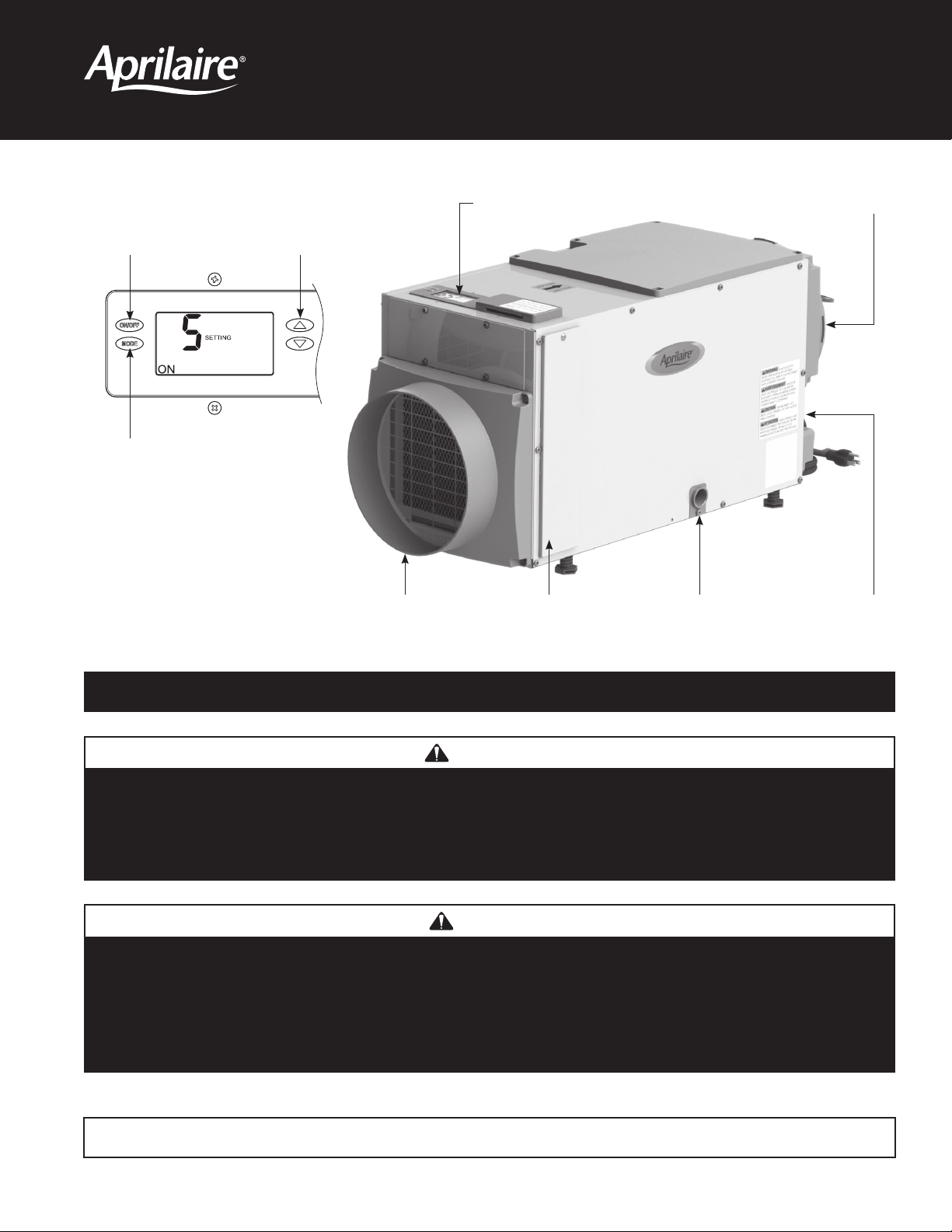
ON/OFF button
used to turn
the ventilator
on and off
MODE button
used to access
ventilation time
setting
90-1874
Up/ Down buttons
used to change
humidity or vent
time setting
Ventilator Control
Inlet Filter Access
Door
Outlet
Drain Power
Switch
SAFETY INSTRUCTIONS
WARNING
1. 120 Volts may cause serious injury from electric shock. Disconnect electrical power before starting installation or servicing.
Leave power disconnected until installation/service is completed.
2. Sharp edges may cause serious injury from cuts. Use care when cutting plenum openings and handling duct work.
3. Dropping may cause personal injury or equipment damage. Handle with care and follow installation instructions.
CAUTION
1. Read all instructions before beginning installation.
2. Improper installation may cause property damage or injury. Installation, service, and maintenance must be performed by a
qualified service technician.
3. Do not use solvents or cleaners on or near the circuit board. Chemicals can damage circuit board components.
4. Wait 24 hours before running the unit if it was not shipped or stored in the upright position
READ AND SAVE THESE INSTRUCTIONS
1

TABLE OF CONTENTS
Safety Instructions......................................................................................................1
Introduction and Compliance Statement ..................................................................................2
Specifications..........................................................................................................3
Set Up Ventilator for Installation .........................................................................................4
Duct Collars ...........................................................................................................4
Control Location........................................................................................................5
Location Considerations.................................................................................................5
Drain Installation .......................................................................................................6
Leveling ..............................................................................................................6
Condensate Pan, Condensate Pump and Float Switch .........................................................................6
Ducting and Wiring .....................................................................................................7
Ducting...............................................................................................................7
Wiring ...............................................................................................................7
Determine Ventilation Requirements .....................................................................................8
Calculating Airflow Requirement ..........................................................................................8
Determine Outdoor Air (CFM) Delivery Rate .................................................................................8
System Set Up and Checkout ............................................................................................9
Ventilation ............................................................................................................9
DEH w/AC ...........................................................................................................10
RH Offset ............................................................................................................10
Installer Test Mode ....................................................................................................10
Start Up and Sequence of Operation.....................................................................................11
Adjusting Ventilation Time After Initial Set Up ..............................................................................11
Maintenance..........................................................................................................12
Clean or Replace the Air Filter ...........................................................................................12
Check the Drain .......................................................................................................12
Troubleshooting .......................................................................................................13
Table 5 – Diagnostic Codes .............................................................................................13
Table 6 – Troubleshooting Guide .........................................................................................14
Service Parts..........................................................................................................15
INTRODUCTION AND COMPLIANCE STATEMENT
The Model 8191 and 8192 Ventilator with Dehumidification is designed to bring outdoor air into today’s efficiently designed homes while
removing moisture from the air. Simply duct the inlet of the ventilator to an outdoor air intake and duct the discharge to the return side of the
HVAC system. Plug the unit in, set the amount of needed ventilation and set the humidity limit.
High temperature limits can be set on the control to prevent bringing in outdoor air during the hottest period of the day. The built in control will
automatically compensate for the ventilation time that is missed by bringing in additional outdoor air during cooler periods of the day. Compliance
with the requirements of ASHRAE 62.2-2010 is met as the control adds ventilation time as needed to account for the fractional on-time and
effectiveness of the ventilation schedule. The control will also ensure that ventilation occurs no less than one hour of every four. When properly
installed and set, the Model 8191 and 8192 Ventilator with Dehumidification will meet the mechanical ventilation requirements of:
Energy Star Certified Homes, Version 3
EPA Indoor airPLUS, Version 1
2012 International Residential Code (IRC)
2012 International Energy Conservation Code (IECC)
2
SPECIFICATIONS
Model 8191 Model 8192
Weight
Moisture Removal Capacity
Power
Inlet Air Conditions
Filter
TABLE 1A – Model 8191 Ventilation Performance
External Static
(“w.c.) Airflow (CFM) Power (W) Current (A) CFM/watt
0 160 63 .57 2.54 4.48
0.1 140 63 .56 2.22 3.97
0.2 120 63 .56 1.90 3.55
0.3 100 63 .56 1.59 3.04
70 pints per day @ 160 CFM
AHAM DH-1-2008 80°F, 60%RH Conditions
115 VAC, Single Phase, 60Hz
9A minimum circuit ampacity
6.3A operating current @ 80°F, 60%RH
67 lbs. 75 lbs.
Ventilation: 40°F – 140°F, 0%RH – 99%RH (non-condensing)
Dehumidification: 50°F – 104°F, 40°F dew point minimum
MERV 8, washable
95 pints per day @ 265 CFM
AHAM DH-1-2008 80°F, 60%RH Conditions
115 VAC, Single Phase, 60Hz
12A minimum circuit ampacity
8A operating current @ 80°F, 60%RH
CFM/watt
FAN ONLY*
0.4 70 62 .56 1.13 2.50
* Unit as just a ventilator (without filtration or dehumidification) provides 245 CFM and uses 69 watts, or 3.55 CFM/watt at 0.2”w.c., meeting the 2012 IECC fan
efficacy requirement.
TABLE 1B – Model 8192 Ventilation Performance
External Static
(“w.c.) Airflow (CFM) Power (W) Current (A) CFM/watt
0 265 153 1.35 1.73 2.84
0.1 245 153 1.34 1.62 2.60
0.2 230 153 1.34 1.50 2.35
0.3 215 153 1.34 1.41 2.13
0.4 200 152 1.33 1.32 1.91
0.5 180 152 1.33 1.19 1.72
0.6 165 151 1.32 1.10 1.50
CFM/watt
FAN ONLY
3
SET UP VENTILATOR FOR INSTALLATION
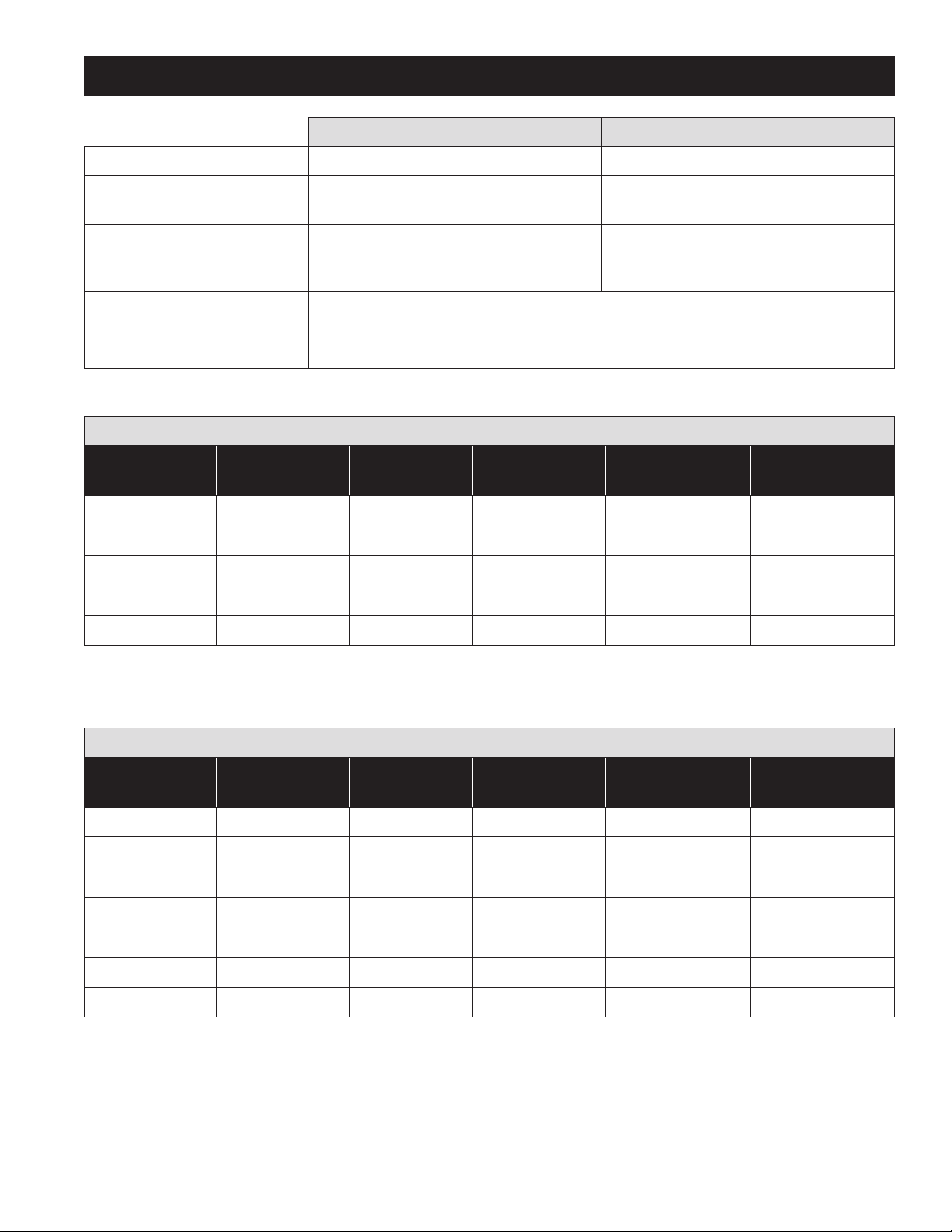
IMPORTANT: Cut the strap securing the compressor
shipping support bracket and remove the strap and shipping bracket.
See Figure 1.
FIGURE 1 – Remove Shipping Bracket
REMOVE SHIPPING BRACKET
CLIP OFF
PLASTIC STRAP
90-1908
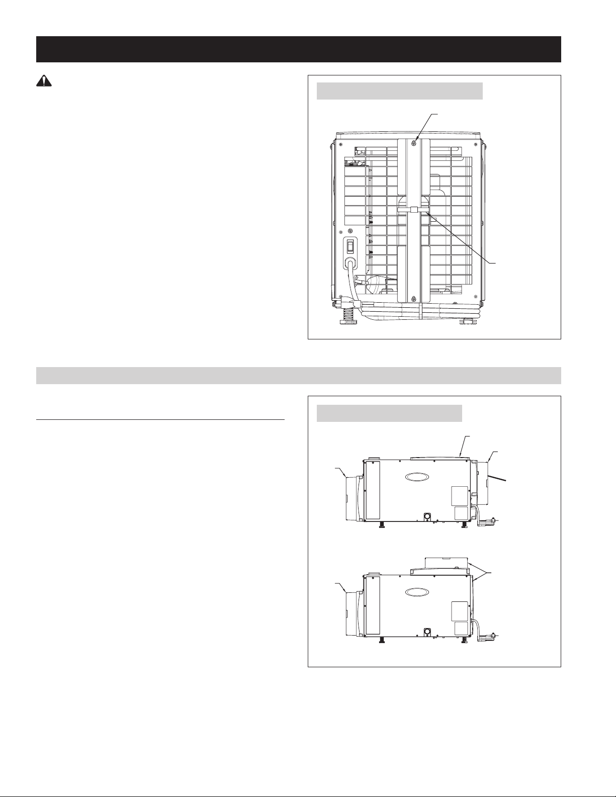
DUCT COLLARS
STANDARD BASEMENT AND ATTIC INSTALLATIONS
(FULLY DUCTED)
• Use the screws in the parts bag to attach the duct collars to the
inlet and outlet of the ventilator. The outlet collar has a backflow
damper.
• The outlet duct collar may be attached to the top or end of the
unit. Move the outlet cover to the location not being used. See
Figure 2.
• Make sure there are no bends in the ductwork coming off the
outlet for a minimum of 4”. This will ensure that the ductwork will
not interfere with the backflow damper function.
FIGURE 2 – Duct Collar Locations
INLET
DUCT
COLLAR
END DISCHARGE
INLET
DUCT
COLLAR
TOP DISCHARGE
OUTLET COVER
OUTLET DUCT
COLLAR W/BACK
DRAFT DAMPER
MOVE OUTLET
COVER AND
INSTALL OUTLET
DUCT COLLAR TO
TOP DISCHARGE
LOCATION
90-1909
4
SET UP VENTILATOR FOR INSTALLATION (CONTINUED)
CONTROL LOCATION
The on-board control can be located on the top of
the ventilator or can be relocated to the front of the
ventilator.
To move the control:
1. Remove the front control panel cover.
FIGURE 3 – Control Location
CONTROL
CONTROL
PANEL COVER
CONTROL
2. Remove the filter access door and filter.
3. Detach the on-board control by removing the four
(4) screws around the control. NOTE: Use one
hand to support the bottom of the on-board control
when removing.
4. Keep the control in the unit and relocate to the
front access hole.
5. Secure the control with the same four screws
used to attach the control to the top of the unit.
6. Secure the control panel cover to the top of the
unit.
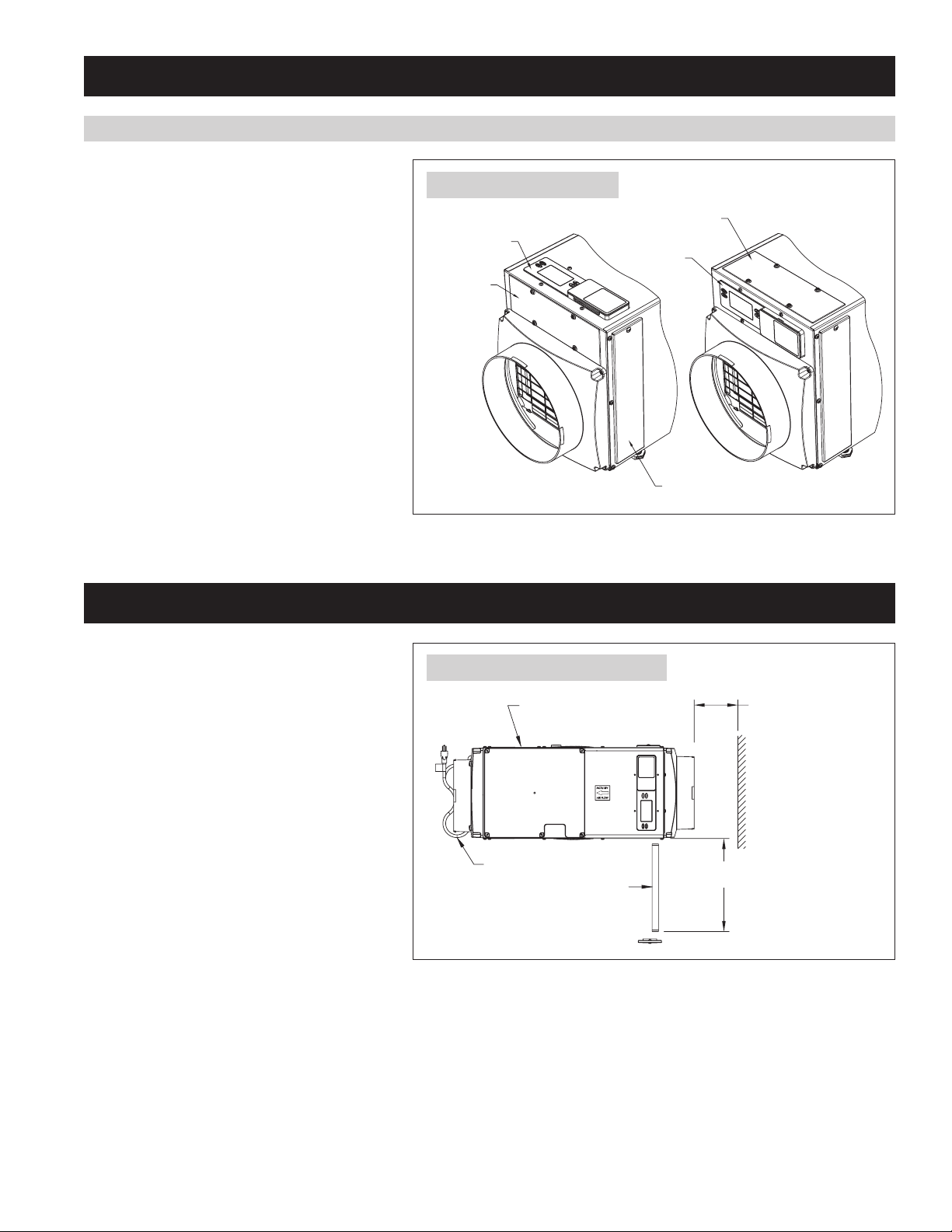
LOCATION CONSIDERATIONS
• Allow sufficient clearance for filter removal and to
prevent airflow obstruction
• Electrical service access will require the removal
of the side panel shown. Allow sufficient space for
service on this side of the unit.
CONTROL
PANEL COVER
FIGURE 4 – Filter Access Clearance
ELECTRICAL SERVICE
ACCESS THIS SIDE
FILTER ACCESS DOOR
90-1884
6" MINIMUM CLEARANCE
FOR PROPER AIR FLOW
• For attic installations, it is recommended that the
ventilator be suspended.
• Always install the ventilator in a condensate pan
when locating in or over a finished space.
6 FT. POWER CORD
TOP VIEW
FILTER
MINIMUM
13"
CLEARANCE FOR FILTER
(EITHER SIDE)
90-1840
5
 Loading...