

Aprilaire 8140, 8140NC Installation Manual
Model 8140 and 8140NC
Fresh Air Ventilator
Installation and Operating Instructions
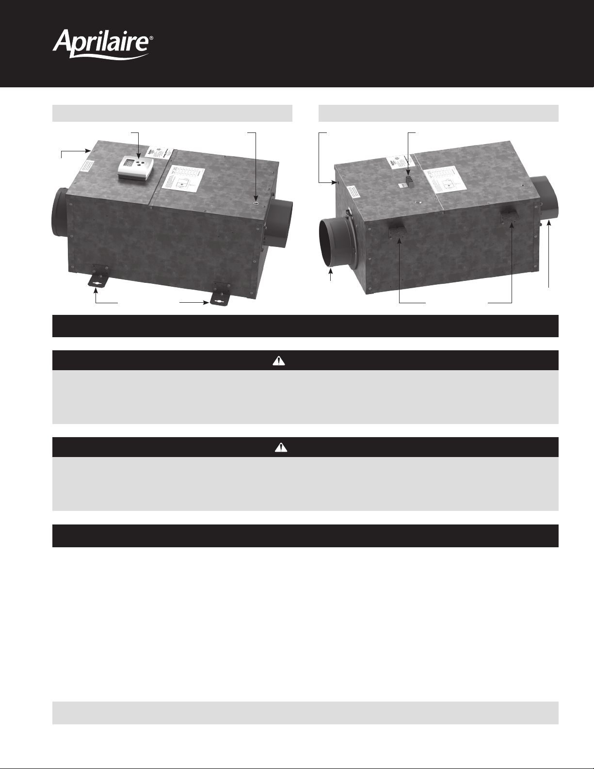
MODEL 8140 FRESH AIR VENTILATOR MODEL 8140NC FRESH AIR VENTILATOR
VENTILATION CONTROLLER
FILTER
COVER
BRACKET LOCATION
WALL MOUNT
INLET COLLAR AND
NORMALLY CLOSED
POWER DAMPER
VENTILATION TERMINALSLOW PRESSURE PORTHIGH PRESSURE PORT
JOIST MOUNT
BRACKET LOCATION
SAFETY INSTRUCTIONS
WARNING
1. 120 Volts may cause serious injury from electric shock. Disconnect electrical power before starting installation or servicing. Leave power
disconnected until installation/service is completed.
2. Sharp edges may cause serious injury from cuts. Use care when cutting plenum openings and handling duct work.
OUTLET
COLLAR
CAUTION
1. Read all instructions before beginning installation.
2. Improper installation may cause property damage or injury. Installation, service, and maintenance must be performed by a qualified service
technician.
TABLE OF CONTENTS
Safety Instructions ...............................................1
Introduction and Compliance Statement ...........................2
Specifications ...................................................2
Install Electrical Outlet............................................2
Ventilator Location and Orientation................................3
Mount the Ventilator .............................................3
Mount Intake Hood ..............................................4
Install Ductwork .................................................4
Model 8140NC – Wiring to Various Controls ........................5
Model 8140NC – Test Mode .......................................6
Model 8140NC – Sequence of Operation ...........................6
Model 8140 – Wiring the Control to the HVAC System ...............6
Model 8140 – Connecting the Control to the Ventilator ..............7
Model 8140 – Operation ..........................................7
Model 8140 – Test Mode ..........................................8
Measure Delivered Airflow ........................................8
Model 8140 – Set Up . . . . . . . . . . . . . . . . . . . . . . . . . . . . . . . . . . . . . . . . . . . . .9
Model 8140 – Rater/Inspector Verification .........................10
Model 8140 – Sequence of Operation .............................10
Filter Cleaning...................................................11
Internal Schematics ..............................................11
Limited Warranty ...............................................12
READ AND SAVE THESE INSTRUCTIONS
10012996 B2208006B 7.19
English 1
INTRODUCTION AND COMPLIANCE STATEMENT
27. 75
10.50
FOR 6" DIAMETER DUCT
FOR 6" DIAMETER DUCT
The Model 8140 and 8140NC Fresh Air Ventilators are designed to bring in precisely the right amount of outdoor air into today’s efficiently designed
homes. Duct the inlet of the ventilator to an outdoor air intake and duct the discharge to the HVAC system, then simply plug the unit in, set the
amount of needed ventilation and select the desired temperature limits.
Temperature limits are set on the control to avoid bringing in outdoor air during the hottest or coldest period of the day. The built in control will
automatically compensate for the ventilation time that is missed by bringing in additional outdoor air during milder periods of the day. Compliance
with the requirements of ASHRAE 62.2-2010 is met as the control adds ventilation time as needed to account for the fractional on-time and
effectiveness of the ventilation schedule. The control will also ensure that ventilation occurs no less than one hour of every four. When properly
installed and set, the Model 8140 and 8140NC Fresh Air Ventilators will meet the mechanical ventilation requirements of:
Energy Star Certified Homes, Version 3
EPA Indoor airPLUS, Version 1
2012 & 2015 International Residential Code (IRC)
2012 & 2015 International Energy Conservation Code (IECC)
California Energy Commission Title 24
SPECIFICATIONS
TABLE 1 – SPECIFICATIONS
External Static Pressure ("w.c.) Airflow (CFM) Efficacy (CFM/watt) Voltage
0.0 250 4.5
0.2 205 3.8
0.4 165 3.1
0.6 125 2.1
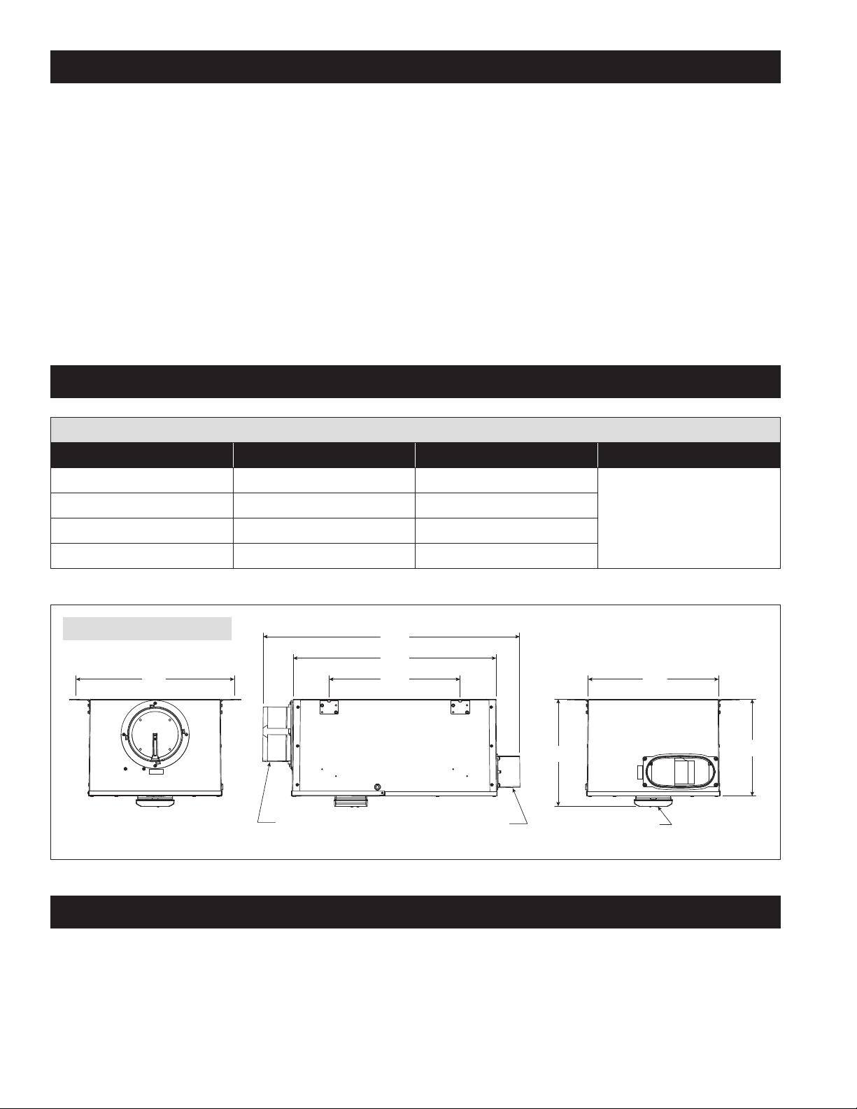
FIGURE 1 – DIMENSIONS (INCHES)
17.15
INLET: ROUND COLLAR
22.13
14.00
OUTLET: OVAL COLLAR
120 VAC
1 phase
60 Hz
14.31
11.60
CONTROL NOT INCLUDED
ON MODEL 8140NC
90-2299
INSTALL ELECTRICAL OUTLET
Install a standard NEMA 5-15 receptacle suitable for the location, near where the ventilator will be installed. The ventilator comes equipped with a
6-foot power cord with a standard 3-prong plug.
2 English
VENTILATOR LOCATION AND ORIENTATION
CAUTION
1. Mount the blower with the lowest, exposed moving parts at
least 8 feet (2.4 m) above floor or grade level.
2. Mount the blower at least 3.3 feet (1.0 m) from any accessible
opening of the duct.
Choose a location for the ventilator that is within 6 feet of the outlet
into which the ventilator will be plugged. Allow space for filter removal
and service as shown in FIGURE 2.
The ventilator can be mounted in any orientation.
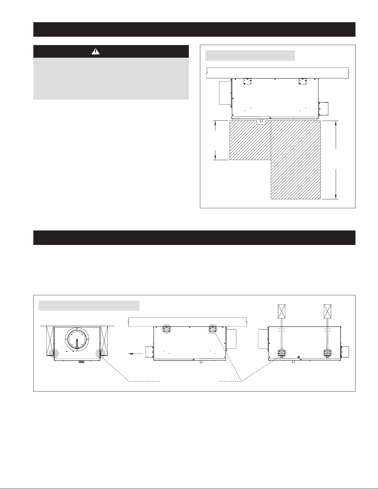
FIGURE 2 – CLEARANCES FOR SERVICING
10"
FILTER
ACCESS
24"
MOTOR
ACCESS
90-2241
MOUNT THE VENTILATOR
1. Install the mounting brackets, using the supplied #8 x 1/2" screws, to the side of the housing as shown in FIGURE 3. Use the holes nearest the
covers for mounting to floor joists or hanging from rafters. Use the holes near the bottom of the unit for mounting to a flat wall or ceiling surface.
2. Secure the ventilator into joists or a strong platform and screw into place using the #10 x 3/4" screws provided. The ventilator weighs
approximately 25 pounds, so do not secure it into drywall alone.
FIGURE 3 – MOUNTING BRACKET POSITIONING
AIR FLOW
MOUNTED TO THE JOIST HUNG FROM THE JOIST
MOUNTED TO WALL OR FLOOR JOISTS
MOUNTING BRACKET LOCATIONS
90-2241
English 3
MOUNT INTAKE HOOD
Install a weather tight hood with a bird screen.
Cut a hole in the exterior wall that is large enough to fit 6" insulated flexible duct through with minimal compression of the insulation. Pull the duct
through the hole and attach the flex duct to the collar of the hood. Use metal foil tape or a plastic zip-tie to secure the duct to the collar. Pull the
insulation and vapor barrier over the duct and tape it to the collar.
IMPORTANT: The end of the insulation must be sealed to prevent condensation from forming inside the insulation. If a plastic zip-tie is used to
secure the insulation to the hood collar, also tape the end to seal it against condensation problems.
Press the hood against the outside wall and secure in place with screws; seal around the perimeter of the hood with caulk.
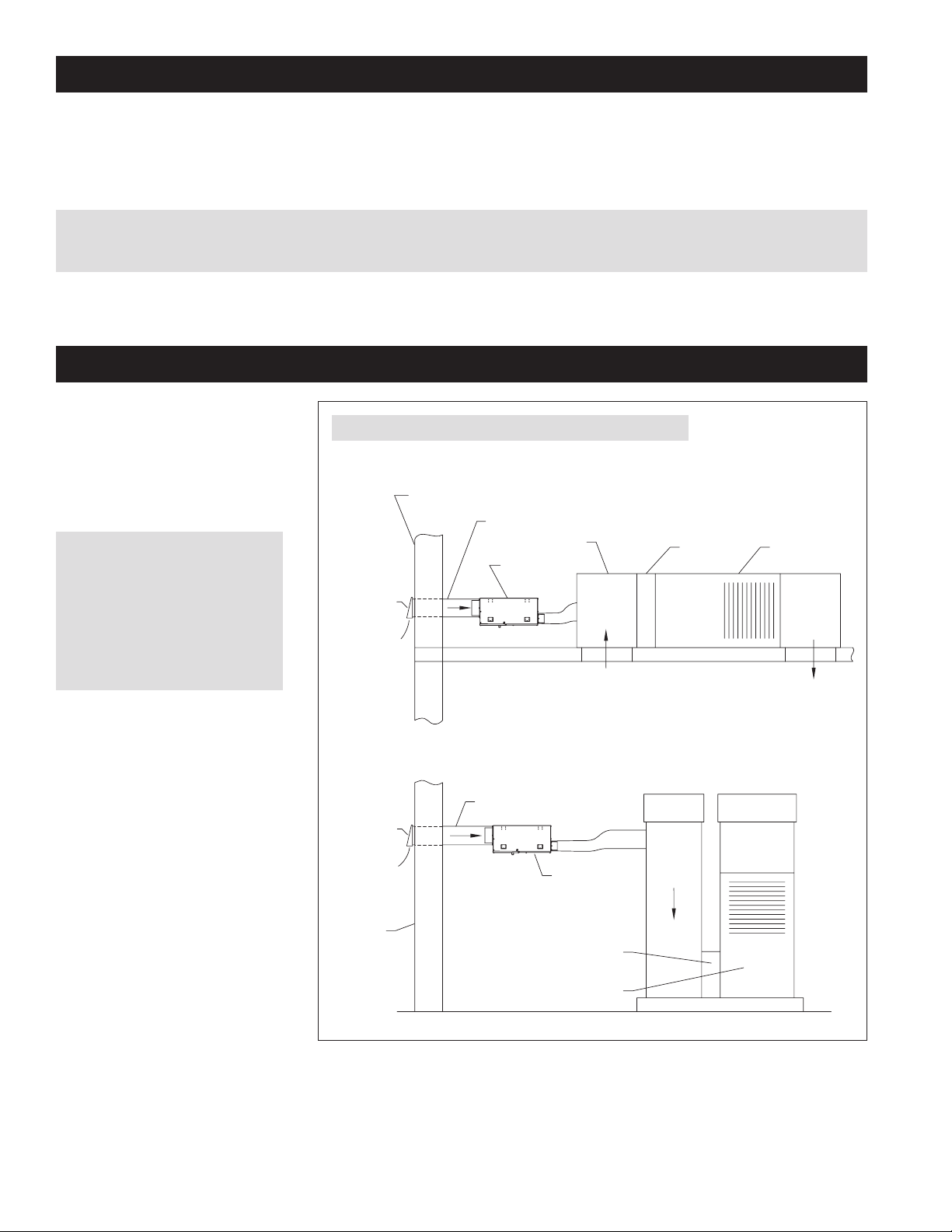
INSTALL DUCTWORK
Install 6" diameter flexible, insulated duct
from the round inlet collar of the unit to the
intake hood and from the oval outlet collar
of the unit to the HVAC system. Duct the
outlet of the ventilator to the return side of
the HVAC system (refer to FIGURE 4).
IMPORTANT: The end of the
insulation must be sealed to prevent
condensation from forming inside
the insulation. If a plastic zip-tie is
used to secure the insulation to the
hood collar, also tape the end to seal
it against condensation problems.
FIGURE 4 – DUCTING IN UPFLOW AND HORIZONTAL HVAC SYSTEMS
TYPICAL ATTIC INSTALLATION
GABLE END WALL, BAND JOIST, OR PORCH SOFFIT
FRESH AIR INTAKE DUCT
RETURN MIXING BOX
FRESH AIR
INTAKE HOOD
WITH SCREEN
FRESH AIR
FRESH AIR
VENTILATOR
AIR FLOW
FILTER
FURNACE/AIR
HANDLER
4 English
FRESH AIR
INTAKE HOOD
WITH SCREEN
FRESH AIR
OUTSIDE
WALL
90-2241
TYPICAL BASEMENT INSTALLATION
FRESH AIR INTAKE DUCT
FRESH AIR
VENTILATOR
AIR FLOW
FILTER
FURNACE/AIR HANDLER
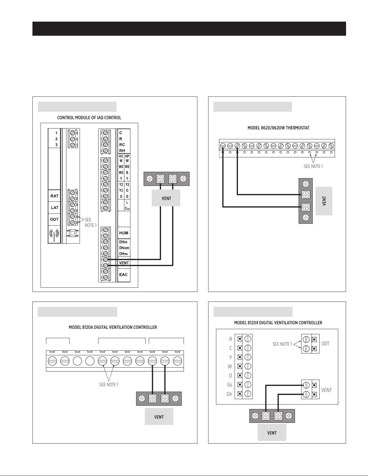
MODEL 8140NC – WIRING TO VARIOUS CONTROLS
CONTROL MODULE OF IAQ CONTROL
VENT
SEE
NOTE 1
MODEL 8120A DIGITAL VENTILATION CONTROLLER
VENT
SEE NOTE 1
MODEL 8620/8620W THERMOSTAT
VENT
SEE NOTE 1
R
C
Y
W
O
Gs
Gh
ODT
VENT
MODEL 8120X DIGITAL VENTILATION CONTROLLER
VENT
SEE NOTE 1
Suggested Controls:
• Aprilaire IAQ Control Models 8910, 8910W or 8920W
• Aprilaire Thermostat Models 8620 or 8620W
• Model 8120A or 8120X Digital Ventilation Controller
Select the diagram that corresponds to the control to be used. Wire the controls to the HVAC equipment and any other IAQ accessory in accordance
with the literature provided with the control.
FIGURE 5 – WIRING TO IAQ CONTROL
FIGURE 6 – WIRING TO THERMOSTAT
C I2
I1 Y
O/B RC
Y2 W2
RG
L T2
S2
W
T1
S1
FIGURE 7 – WIRING TO MODEL 8120A
NOT
CR VENTODT GfUSED
NOTE 1: An outdoor temperature sensor must be installed to use outdoor temperature limits for ventilation control.
FIGURE 8 – WIRING TO MODEL 8120X
OUTPUTSINPUTSPOWER
GW
English 5
MODEL 8140NC – TEST MODE
CONTROL
MOUNTING
PLATE
VENTILATION CONTROL
RCYWG
RCYWG
THERMOSTAT
WIRE NUT
(FIELD
SUPPLIED)
R
C
Y
W
O
GS
GH
FURNACE
R & C = 24 VAC
Y = COOLING
W = HEAT
GS = FAN INPUT
GH = FAN OUTPUT
VENT
ODT
After all ducting and wiring is complete, plug in the ventilator, restore power to the HVAC system and make sure the switch controlling the outlet into
which the ventilator is plugged (if applicable) is turned on.
1. Use the installed control to complete a circuit between the VENT terminals on the 8140NC.
2. Verify that the ventilator blower starts and that the integral damper opens.
3. If the ventilator has been wired to turn on the HVAC blower with ventilation, verify that the blower is on.
4. Measure the airflow (CFM) that the installed ventilator is delivering. See MEASURE DELIVERED AIRFLOW section on page 8.
5. Using the instructions provided with the installed control, adjust the ventilation settings as required.
MODEL 8140NC – SEQUENCE OF OPERATION
Refer to the installation manual provided with the control that is wired to the Model 8140NC.
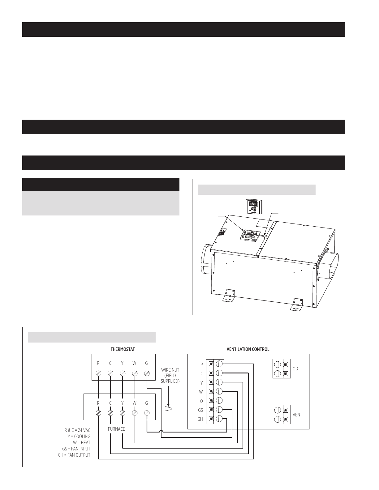
MODEL 8140 – WIRING THE CONTROL TO THE HVAC SYSTEM
NOTICE
Disconnect power to HVAC system during wiring to avoid
electrical shorts.
1. Remove the control from the mounting plate as shown in FIGURE 9.
Set control aside in a safe place until all wiring has been completed.
2. Run a 6-conductor (min.) cable (for furnace/AC applications) or a
7-conductor (min.) cable between the control and the HVAC system.
3. Wire to the HVAC system in accordance with FIGURE 10 if installed in
a furnace/AC application or FIGURE 11 if installed with a heat pump.
FIGURE 10 – WIRING VENTILATION CONTROL TO A FURNACE
FIGURE 9 – REMOVE CONTROL FROM MOUNTING PLATE
CONTROL
CONTROL CONNECTOR
90-2299
6 English
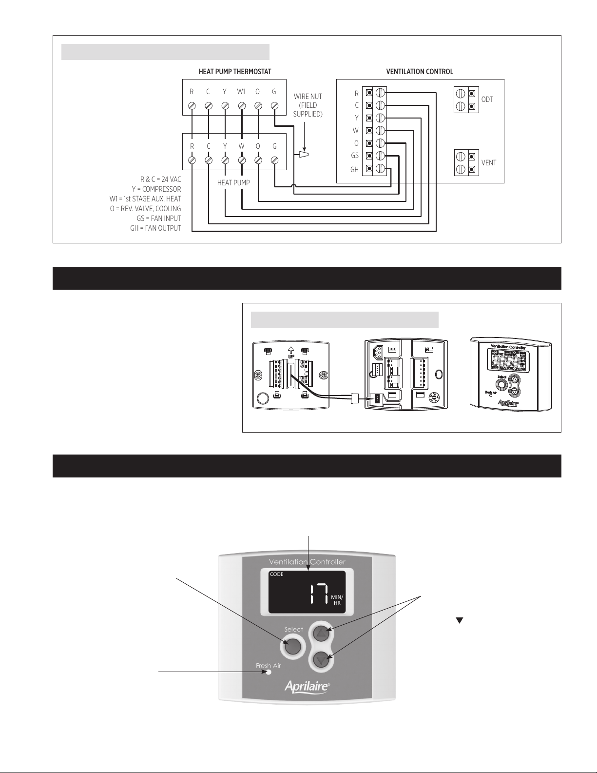
VENTILATION CONTROL
RCYW1G
RCYWG
HEAT PUMP THERMOSTAT
WIRE NUT
(FIELD
SUPPLIED)
O
R & C = 24 VAC
Y = COMPRESSOR
W1 = 1st STAGE AUX. HEAT
O = REV. VALVE, COOLING
GS = FAN INPUT
GH = FAN OUTPUT
R
C
Y
W
O
GS
GH
VENT
ODT
HEAT PUMP
O
FIGURE 11 – WIRING VENTILATION CONTROL TO A HEAT PUMP
CONTROL BACK CONTROL FRONTCONTROL MOUNTING PLATE
MIN/
HR
CODE
MODEL 8140 – CONNECTING THE CONTROL TO THE VENTILATOR
Plug the Control Connector into the back of the
control at the location shown in FIGURE 12. Route
the connector wire through the channels in the
control and reattach the control to the mounting
plate. Restore power to the HVAC system and plug
in the ventilator when complete.
FIGURE 12 – PLUG THE CONTROL INTO THE VENTILATOR
MODEL 8140 – OPERATION
The display will appear faint normally; the first press of any button will turn on the display at full power.
Shows the ventilation time setting (minutes/hr), mode of operation
(Code or Comfort) and whether the HVAC fan has been turned on when ventilating.
Use for Rater/Inspector Verification.
Press and hold for 5 seconds to
enter Test Mode or Set Up Menu.
Lights green when ventilating.
90-2291
Use to override the calculated ventilation
time setting (6 – 60 minutes/hr). Press
and hold to turn ventilation OFF.
To return to the calculated setting, go
completely through the Set Up Menu.
English 7
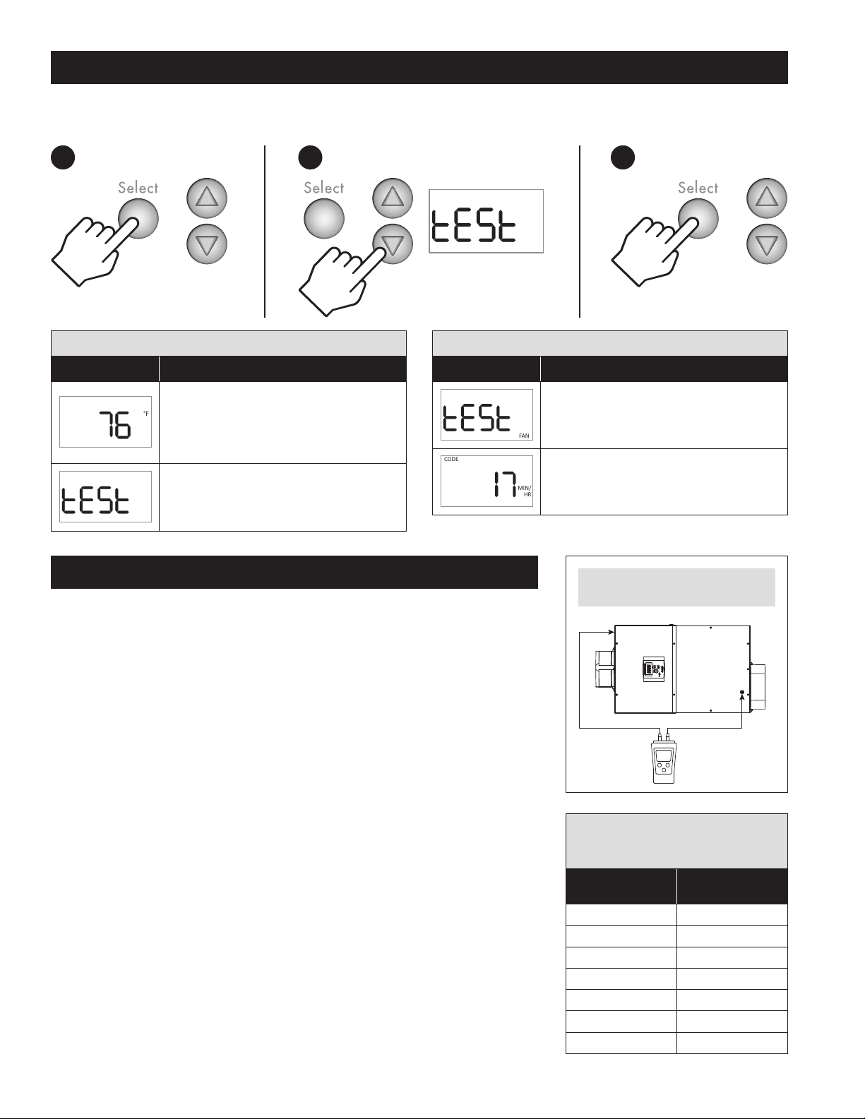
MODEL 8140 – TEST MODE
2 3
HP°FHC
1
MEASURED REQ’D CONT CFM
FAN
MIN/
HR
CODE
After wiring and set up have been completed, Test Mode can be used to verify that all components in the ventilation system function and that wiring
to the HVAC system fan is correct.
Hold for 5 seconds.
TABLE 2 – MODEL 8140 TEST MODE MENU
Test Sequence Description
Shows outdoor temperature or ----°F if no
separate outdoor temperature sensor has been
%
installed. Model 8140 installations do not require a
separate sensor – outdoor temperature is measured
by the control's on-board sensor.
tESt shows on the display, the green Fresh Air LED
will light and either the damper will open or the
power ventilator will turn on depending on what
has been wired to the VENT terminals.
TABLE 2 – MODEL 8140 TEST MODE MENU
Test Sequence Description
After 15 seconds, the HVAC fan will turn on if it has
been wired and set up to do so. The display will
show FAN along with tESt.
After 45 seconds Test Mode automatically
completes and the display returns to the operating
display.
MEASURE DELIVERED AIRFLOW
1. Make sure the ventilator is plugged in and wired to an external control (Model 8140NC) or that
the integral control is wired to the HVAC system (Model 8140).
2. Use 1/4" flexible tubing to attach a pressure gauge set to " w.c. (sometimes shown as “in. w.g.”
or “in. H2O”) to the inlet and outlet pressure ports on the ventilator. The pressure gauge should
have as small a range as possible to get a meaningful measurement – a range of 1.0" w.c. should
be sufficient. Connect the high or “+” port of the gauge to the outlet pressure port on the
ventilator, and the low or “-“ port of the gauge to the inlet pressure port on the ventilator. See
FIGURE 13.
3. Model 8140NC – Turn on the ventilator using the installed control for the Model 8140NC. This
can be done by temporarily changing the ventilation setting to 60 minutes/hour or you can
simply place a jumper between the VENT terminals of the ventilator.
Model 8140 – Turn on the ventilator by using the “Up” button to increase the ventilation setting
to 60 MIN./HR.
4. Use the label on the cover of the ventilator, or TABLE 3, to convert the pressure reading to
delivered airflow. If the pressure reading false between listed values, either use the lower value
or interpolate between values: CFM = Lower Value + [(Higher Value – Lower Value) * 10 *
(Pressure Reading – Lower Value Pressure)]. The following is an example:
a. Measured Pressure Reading is 0.34" w.c.
b. Table 2 lists 205 CFM @ 0.3" w.c. and 175 @ 0.4" w.c.
c. Either use 175 CFM or interpolate:
CFM = 175 + [(205-175) * 10 * (0.34-0.3)] = 175 + [(30) * 10 * (.04)] = 175 + 12 = 187 CFM
Interpolating will demonstrate higher delivered airflow, but requires a calculation to be done.
FIGURE 13 – MEASURE PRESSURE AT
INLET AND OUTLET PRESSURE PORTS
Lo
INLET
Hi
-
+
90-2354
TABLE 3 – DELIVERED AIRFLOW
CORRESPONDING TO MEASURED PRESSURE
AT VENTILATOR PRESSURE PORTS
Measured Pressure
(" w.c.)
0.1 250
0.2 230
0.3 205
0.4 175
0.5 145
0.6 110
0.7 70
Delivered Airflow
(CFM)
OUTLET
8 English
 Loading...