

Page 1

Xserve (Late 2006/Early 2008)
Rear ID Tab
Replacement Instructions
Follow the instructions in this document carefully. Failure to follow these instructions could
damage your equipment and void its warranty.
Online instructions are available at http://www.apple.com/support/diy/.
Working Safely Inside the Xserve
Always touch the Xserve enclosure to discharge static electricity before you touch any
components inside the Xserve. To avoid generating static electricity, do not walk around the
room until you have nished working inside the server and have replaced the cover. To minimize
the possibility of damage due to static discharge, wear an antistatic wrist strap while you work
inside the Xserve.
Warning: Always shut down the Xserve and disconnect the power cords before opening
it to avoid damaging its internal components or the components you are installing. Don’t
open the server while it is turned on. Even after you shut down the Xserve, its internal
components can be very hot. Let it cool before you open it.
Tools Required
The following tools are required for this procedure:
Phillips #1 screwdriver•
Antistatic wrist strap (if available)•
2 thermal grease syringes for replacing processor heat sinks (supplied with the replacement •
part)
2 alcohol wipes for cleaning processors and heat sinks (supplied with the replacement part)•
073-1112 Rev. B
Page 2
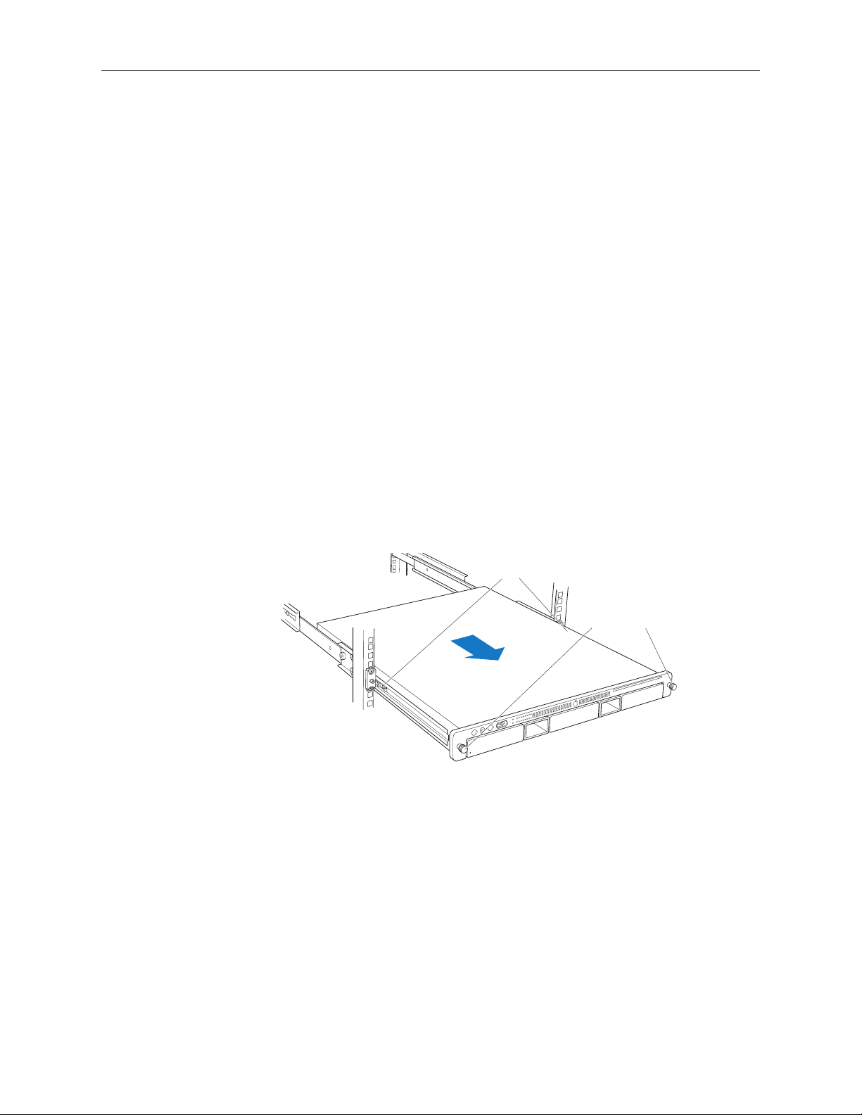
Removing the Xserve from a Rack
Latches
Thumbscrews
Alert users that the server will be unavailable for a period of time. 1.
Shut down the Xserve (see the Xserve User’s Guide for help) and then wait to let the Xserve 2.
internal components cool.
Warning: Always shut down the Xserve before opening it to avoid damaging its internal
components or the components you want to install or remove. Don’t open the Xserve
or try to install or remove items inside while it is turned on. Even after you shut down
the Xserve, its internal components can be very hot. Let it cool down for 5 to 10 minutes
before you open it.
Unplug all cables from the Xserve. 3.
Note: If you have trouble releasing a cable from the back panel, try using a small screwdriver
or other at tool to depress the tab on the cable connector.
To avoid inadvertently unlatching a drive module during handling, use the enclosure key to 4.
lock the enclosure lock on the front panel.
Touch the server’s metal case to discharge any static electricity. 5.
Loosen the thumbscrews at both ends of the front panel.6.
Grasp the thumbscrews and pull the Xserve forward until the safety latches engage (about 7.
halfway out of the rack).
When the safety latches engage, grip the Xserve where it emerges from the rack, press down 8.
on the latch tabs with your thumbs, and slide the Xserve the rest of the way out of the rack
rails.
Set the Xserve on a at surface and unlock it. 9.
Xserve (Late 2006/Early 2008) Rear ID Tab Replacement Instructions 2
Page 3
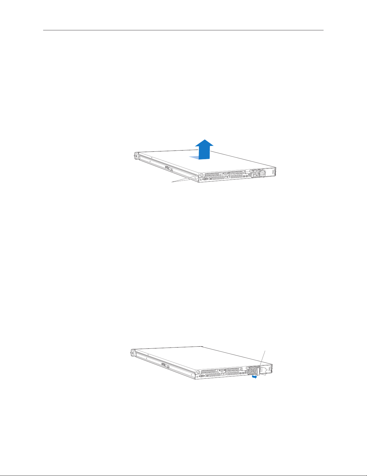
Opening the Xserve
Unscrew the two
captive thumbscrews.
Slide the cover back and lift it off.
Pull the handle to unlatch the
power supply and remove it.
Loosen the thumbscrews at the back of the top cover and slide the cover back and up to remove
it. If you have diculty removing the cover, check the enclosure lock on the front panel.
Warning: Even after you shut down the Xserve, its internal components can be very hot. Let
it cool before you open it.
Important: To minimize the possibility of damage to Xserve components due to static discharge,
wear an antistatic wrist strap, if possible, while you work inside the Xserve.
Removing the Installed Rear ID Tab
Before removing the installed rear ID tab, remove the following parts:
Both power supplies•
PCI riser cards and any expansion cards in both slots (if installed)•
Airow duct•
Fan array•
Backplane-to-logic board I/O cable•
Both processor heat sinks•
Logic board•
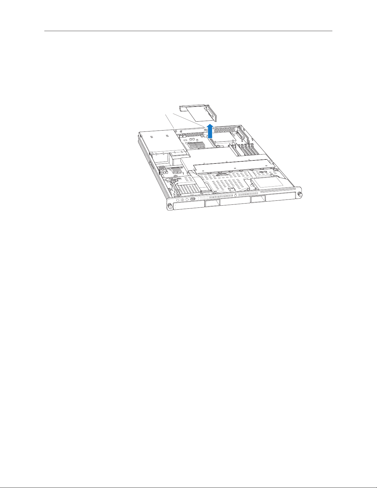
Power Supplies
Pull the handle to release the rst power supply and slide it out of the bay. 1.
Repeat for the second power supply, if installed.2.
Xserve (Late 2006/Early 2008) Rear ID Tab Replacement Instructions 3
Page 4
PCI Riser Cards and Expansion Cards
Captive screws
Loosen the two captive screws that secure the riser bracket in slot 1 to the back panel.1.
Carefully pull up on the bracket and riser, with the expansion card still attached, to 2.
disconnect the riser from the logic board.
Tilt the expansion card up so that its port clears the enclosure, and remove the card from the 3.
Xserve.
Repeat for the riser card in slot 2. 4.
Xserve (Late 2006/Early 2008) Rear ID Tab Replacement Instructions 4
Page 5
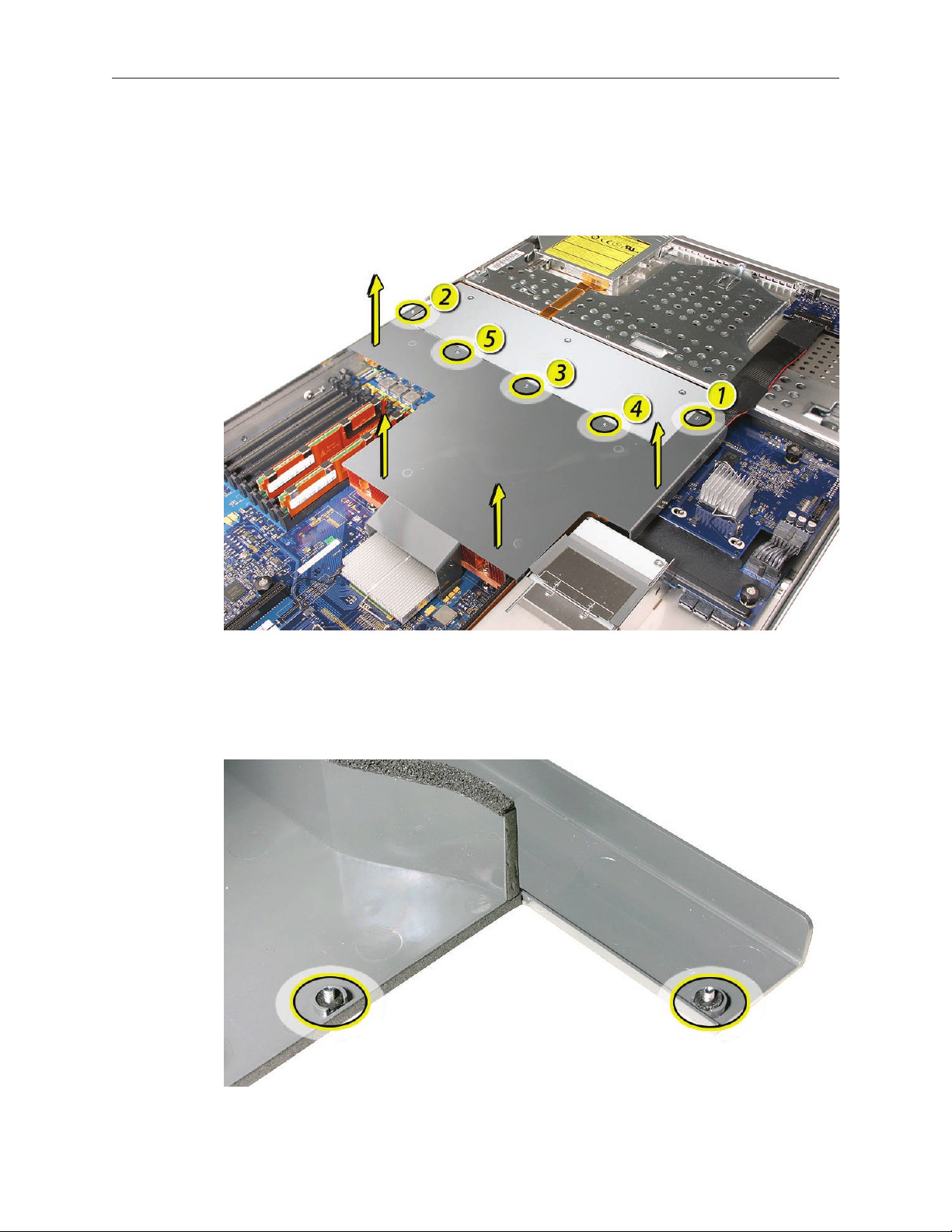
Airow Duct
Loosen the ve Phillips screws that fasten the airow duct to the fan array.1.
Pull up on either side of the airow duct, and lift it straight up and out of the Xserve. 2.
Caution: Try not to completely remove the screws from the airow duct. Tiny black rubber
washers hold these screws captive on the underside of the airow duct. If the screws are
completely removed, these rubber washers can easily fall into the enclosure and become
lost.
Xserve (Late 2006/Early 2008) Rear ID Tab Replacement Instructions 5
Page 6
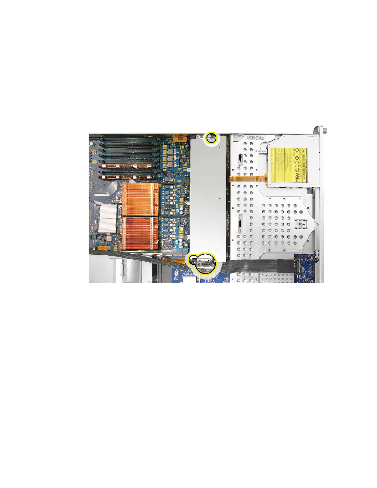
Fan Array
Loosen the two thumbscrews that secure the fan array to the enclosure. 1.
Note: The thumbscrews are captive; you cannot remove them.
Lift the fan array to remove it from the Xserve. 2.
Note: You may need to move the front panel cable slightly out of the way of the fan array
power connector during removal or replacement. Be careful not to pinch the front panel
board cable between the fan array and any other surface inside.
Xserve (Late 2006/Early 2008) Rear ID Tab Replacement Instructions 6
Page 7
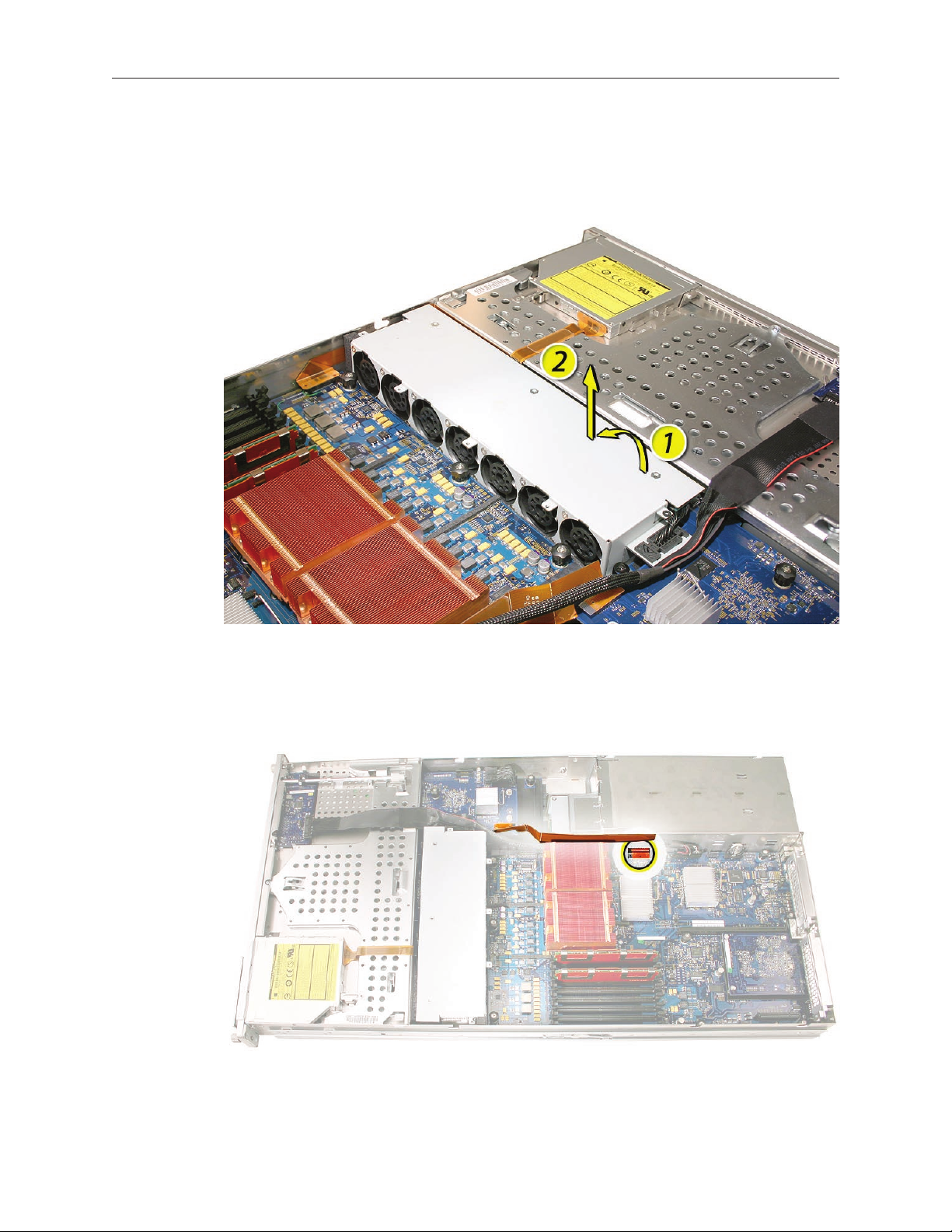
Note: You may encounter some resistance around the fan array power connector during removal.
If so, carefully rotate the fan array as shown to disconnect it from the power distribution board
below, and then lift the fan array out of the computer.
Backplane-to-Logic Board I/O Cable
Disconnect the backplane-to-logic board cable from the logic board. 1.
Xserve (Late 2006/Early 2008) Rear ID Tab Replacement Instructions 7
Page 8
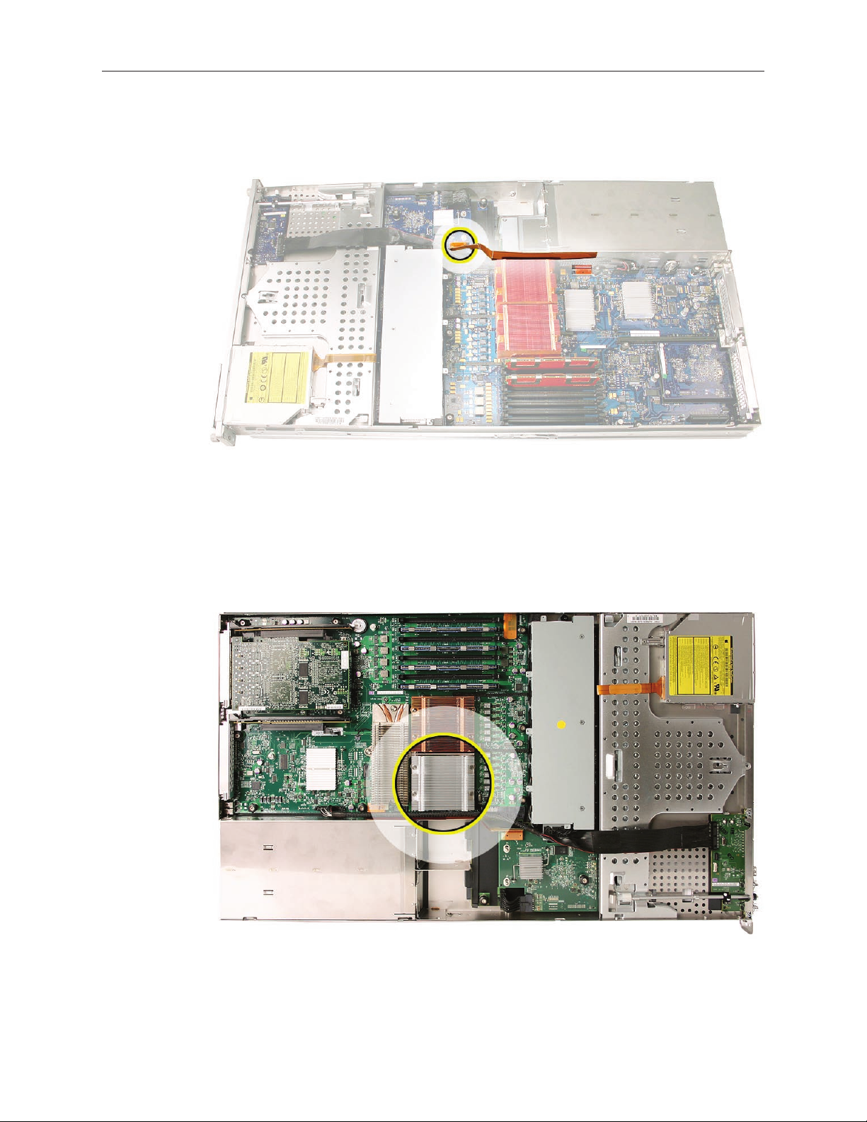
Disconnect the backplane-to-logic board cable from the drive interconnect backplane and 2.
remove the cable from the Xserve.
Processor Heat Sinks
Note: Server congurations with a single processor have a regular heat sink and a blank heat sink
installed. The blank heat sink is silver colored (as shown below) and should not be removed
except when replacing a logic board.
Xserve (Late 2006/Early 2008) Rear ID Tab Replacement Instructions 8
Page 9
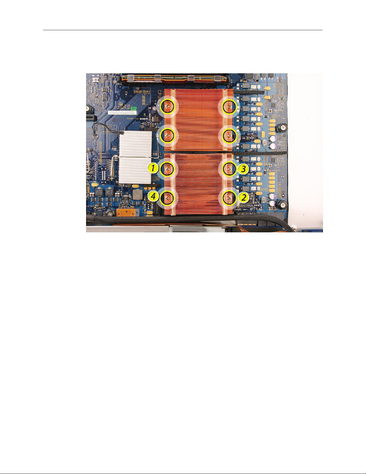
Loosen the four screws securing the heat sink in the order indicated below. If two copper-1.
colored heat sinks are installed, you must remove both heat sinks.
Xserve (Late 2006/Early 2008) Rear ID Tab Replacement Instructions 9
Page 10
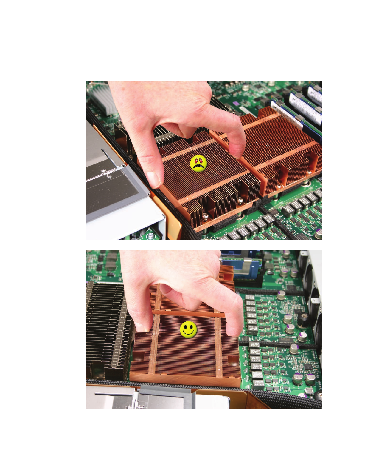
Caution: Whenever you handle a heat sink, handle it from the slotted sides, not the smooth
sides. Grasping the smooth sides of the heat sink can compress its ribs causing permanent
damage.
Xserve (Late 2006/Early 2008) Rear ID Tab Replacement Instructions 10
Page 11
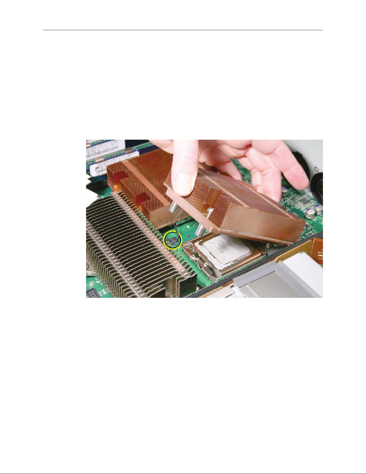
Caution: Each heat sink is connected to the logic board by a small 2-pin thermal sensor 2.
cable. Lifting the heat sink too quickly can damage the cable or connector. Because of
the tight thermal bond between the processor and heat sink, be especially cautious to
initially lift the heat sink no more than one centimeter (1 cm) o the processor. Do not
pull on the cable as you lift each heat sink enough to disconnect the cable from the
logic board.
Slowly raise the heat sink o the processor just far enough that you can reach the sensor
cable connector.
Pull on the connector, not the cable, to disconnect the sensor cable from the logic board. 3.
Lift the heat sink straight up and out of the enclosure.4.
Using an alcohol wipe, clean o any thermal grease from the underside of the heat sink. Save 5.
the alcohol wipe package for later.
Note: You will need to clean o the old thermal grease from the bottom of each heat sink
and the top of each processor and apply new thermal grease to the processors when you are
reassembling the Xserve. For more information, see “Replacing the Processor Heat Sinks.””
Xserve (Late 2006/Early 2008) Rear ID Tab Replacement Instructions 11
Page 12
Logic Board
Study the next four images for properly moving the logic board before continuing with the 1.
steps.
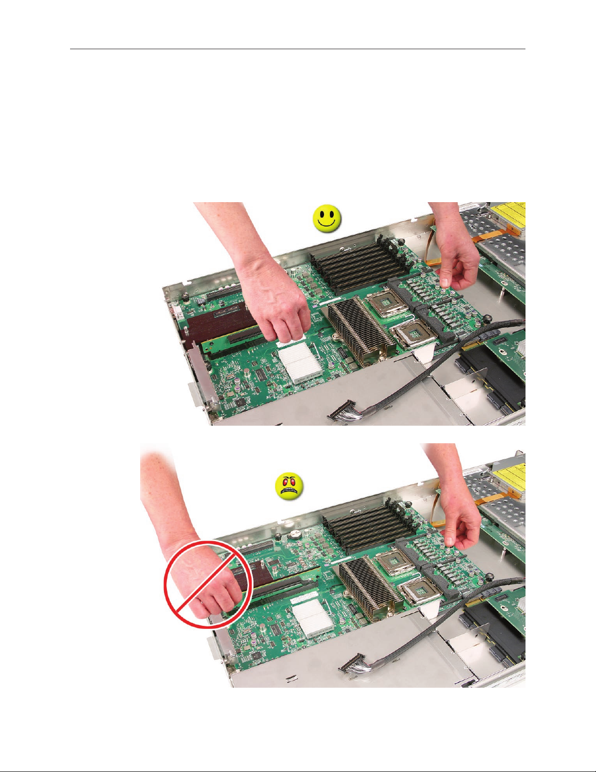
Caution: When removing and installing the logic board, be careful not to ex the logic board,
which could damage the board or its components. To best distribute the weight of the logic
board and minimize exing, grasp the logic board only at the side and the end of the expansion
card riser, as shown.
Xserve (Late 2006/Early 2008) Rear ID Tab Replacement Instructions 12
Page 13
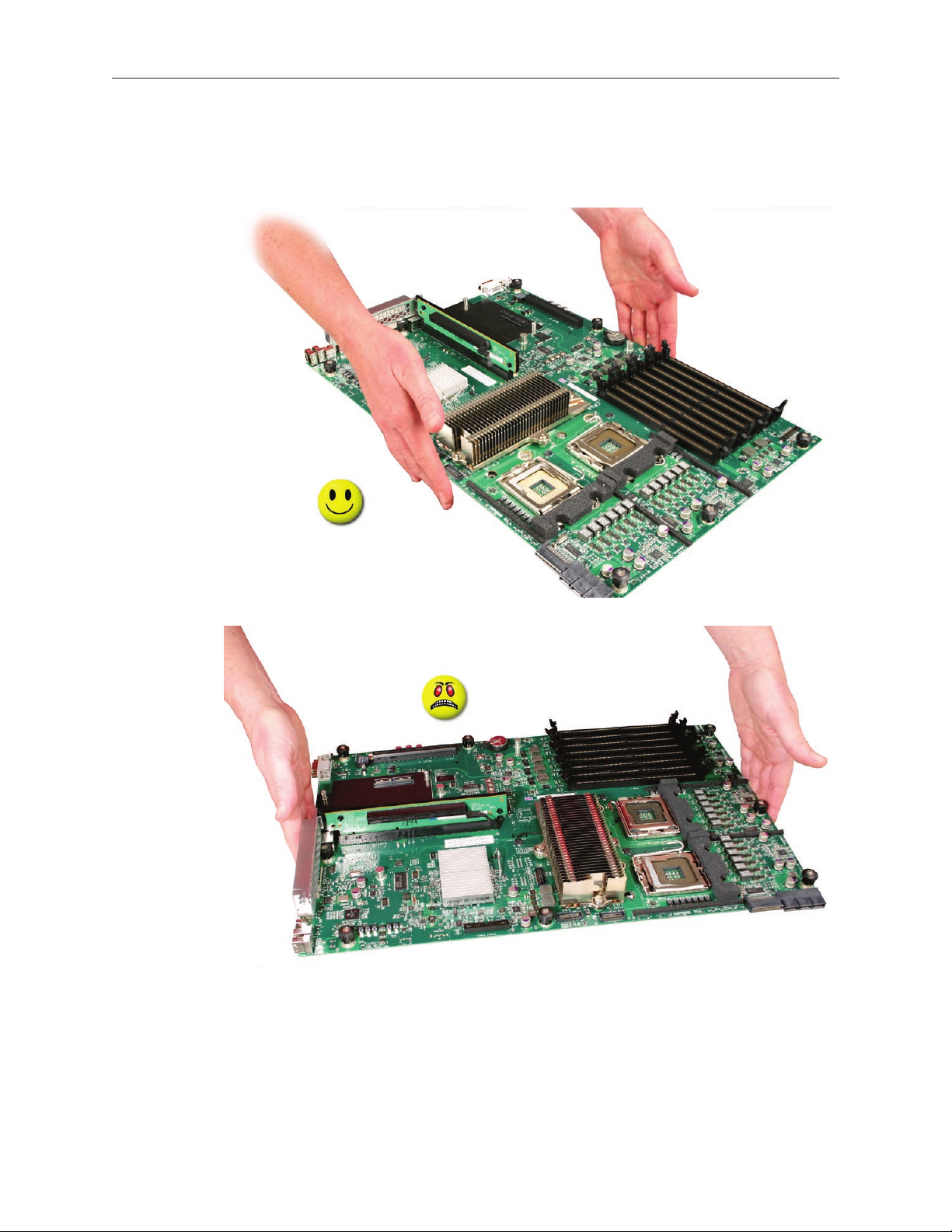
Caution: When transferring the logic board, be careful not to ex the logic board, which could
damage the board or its components. To best distribute the weight of the logic board and
minimize exing, hold the logic board at the long sides near the center, as shown.
Xserve (Late 2006/Early 2008) Rear ID Tab Replacement Instructions 13
Page 14

Disconnect the optical drive cable from the logic board.2.
Release the two locking levers on the front panel board cable connector and disconnect the 3.
cable from the logic board. Move the cable aside so you have access to the logic board.
Loosen the single thumbscrew on the power distribution board and slide the board away 4.
from and out of the connector on the logic board.
Note: Don’t remove the power distribution board but make sure its edge connector is all the
way out of the connector on the logic board.
Xserve (Late 2006/Early 2008) Rear ID Tab Replacement Instructions 14
Page 15
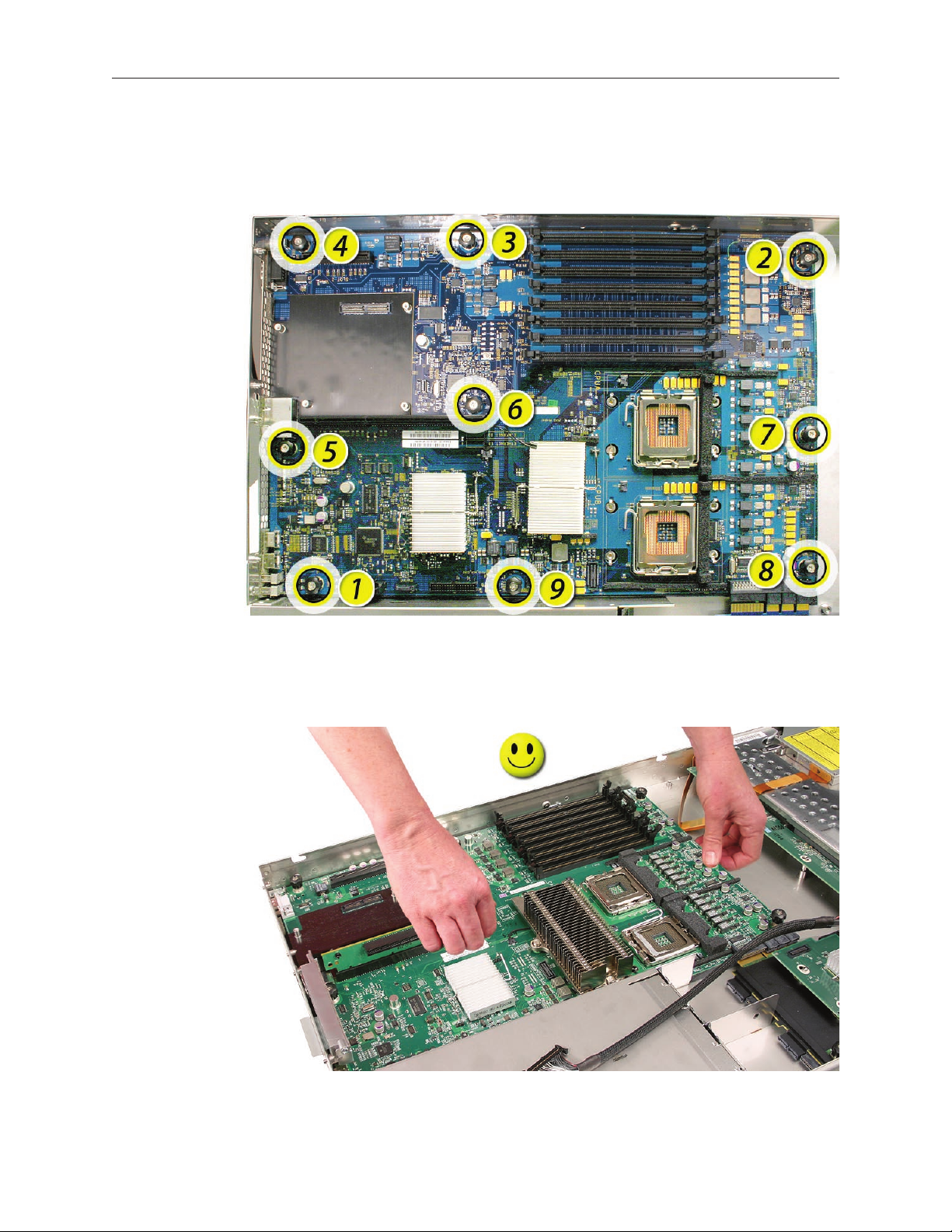
Following the order shown, loosen the nine thumbscrews that secure the logic board to the 5.
enclosure.
Note: The thumbscrews are captive; you cannot remove them.
Grasping the logic board only by its expansion card riser and edge as shown, move it 6.
forward and up slightly to release it from the rear port openings in the enclosure.
Remove it from the Xserve.7.
Xserve (Late 2006/Early 2008) Rear ID Tab Replacement Instructions 15
Page 16

Rear ID Tab
Note: The rear ID tab protrudes from the rear panel through a slot.
Locate the rear ID tab. Once the logic board has been removed from the enclosure, the ID 1.
tab is visible on the inside bottom of the enclosure.
Xserve (Late 2006/Early 2008) Rear ID Tab Replacement Instructions 16
Page 17

Gently grasp the ID tab and pull up on it to disengage it from the channel that it slides along 2.
in the enclosure.
Pull the ID tab through the slot in the rear panel to remove it.3.
Xserve (Late 2006/Early 2008) Rear ID Tab Replacement Instructions 17
Page 18

Installing the Replacement Rear ID Tab
Insert the replacement rear ID tab through its slot in the rear panel. Make sure the tab engages
with the channel that it slides along in the enclosure.
Replacing the Logic Board
Important: When replacing the logic board, make sure the board’s rear port connectors t
through the appropriate openings in the Xserve’s back panel. Take special care to t the rear ID
button through its opening. Don’t bend or ex the logic board.
With the front edge of the board raised 1–2 inches (3–5 cm), guide the connectors on the 1.
back edge of the board into the openings in the back panel of the enclosure, and then lower
the front edge of the board into place.
Xserve (Late 2006/Early 2008) Rear ID Tab Replacement Instructions 18
Page 19

Following the order shown, use a screwdriver to tighten, but not overtighten, the nine 2.
thumbscrews that secure the logic board to the enclosure.
Slide the power distribution board back into place and tighten the thumbscrew. 3.
Note: Make sure the edge connector on the power distribution board goes completely into
the connector on the logic board. If the power distribution board doesn’t slide easily, make
sure the thumbscrew is popped up so it doesn’t catch on the mounting post beneath the
board.
Reconnect the front panel board cable and the optical drive cable to the logic board.4.
Replacing the Processor Heat Sinks
Note: You will need to clean o the old thermal grease from the bottom of each heat sink and
the top of each processor. You will then need to apply new thermal grease to the top of each
processor, before re-installing the heat sink onto the processor.
Clean o any existing thermal grease on the heat sink using the alcohol wipes provided with 1.
the thermal grease. Keep the package that the wipes came in for use later.
Release the latch on the metal processor holder for the processor.2.
Xserve (Late 2006/Early 2008) Rear ID Tab Replacement Instructions 19
Page 20

Rotate the top of the holder to the open position. 3.
Carefully lift the processor out of the holder. 4.
Important: When removing or installing a processor, always hold the processor by three
corners. Be extremely careful not to touch the gold pins on the bottom of the processor, as
this type of connector is very sensitive to contamination. Also be careful not to touch the
gold pins in the processor socket on the logic board.
Xserve (Late 2006/Early 2008) Rear ID Tab Replacement Instructions 20
Page 21

Using the syringe of thermal grease, apply the entire contents of the syringe (approximately 5.
4.5 cc) to the top surface of the processor.
Important: Be sure not to get grease anywhere on the processor other than the very top, at
surface that directly contacts the heat sink.
Use the edge of the package that the alcohol wipe came in as a spatula to spread the 6.
thermal grease evenly over the entire top surface of the processor. Scrape o any excess
grease with the package edge, then discard the package.
Xserve (Late 2006/Early 2008) Rear ID Tab Replacement Instructions 21
Page 22

Holding the processor by three corners only, keep the processor level as you place it into its 7.
holder on the logic board, being careful not to get any thermal grease on the contacts of
either the processor or its socket holder.
Xserve (Late 2006/Early 2008) Rear ID Tab Replacement Instructions 22
Page 23

Note: When installing the processor on the logic board, align the processor notch with the
tab on the processor holder, as shown. Then lower the processor straight down onto the
socket.
Rotate the top of the holder to the closed position.8.
Engage the latch on the metal processor holder. Repeat the steps above for the second 9.
processor.
Holding the heat sink by the slotted sides in one hand, reconnect the 2-pin thermal sensor 10.
cable for the heat sink to the logic board.
Note: Make sure the connector on the sensor cable is oriented as shown, with the gold
ngers facing up.
Xserve (Late 2006/Early 2008) Rear ID Tab Replacement Instructions 23
Page 24

Carefully seat the heat sink over the processor, aligning the four screws with the holes in the 11.
logic board.
Tighten the four captive Phillips mounting screws for the heat sink in the order indicated 12.
below. Do not over-tighten the screws. If you have a torque driver, tighten the screws to 8
inch-pounds; otherwise, try to tighten the screws with equal pressure.
Replacing the Backplane-to-Logic Board I/O Cable
Fold the replacement cable to a 90-degree angle along its creases. 1.
Xserve (Late 2006/Early 2008) Rear ID Tab Replacement Instructions 24
Page 25

Connect the cable to the logic board rst. Then press the adhesive section of the cable onto 2.
the enclosure before connecting the other end of the cable to the backplane.
Caution: Make sure the cable is fully seated.
Replacing the Fan Array
Align the power connector on the fan array with its connector on the power distribution 1.
board and lower the array into the enclosure. Push down on the fan array power connector
to make sure it is fully seated.
Tighten the screws at the ends of the array. Make sure the large front panel board cable runs 2.
above the power connector but below the tab on the top of the power supply.
Xserve (Late 2006/Early 2008) Rear ID Tab Replacement Instructions 25
Page 26
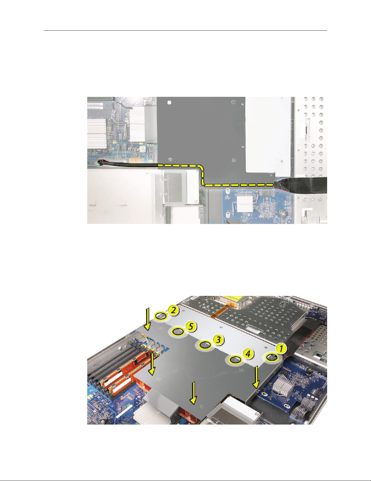
Replacing the Airow Duct
Lower the airow duct into position on the logic board. 1.
Note: When installing the airow duct, be sure to route both the front panel board cable and
the backplane-to-logic board I/O cable inside the channel under the left side of the duct.
Ensure the airow duct ts ush all over, and does not protrude above the level of the 2.
enclosure.
Note: Be careful when working with any black foam pieces that are part of the airow duct
or the logic board.
Tighten the ve Phillips screws that fasten the airow duct to the fan array, in the order 3.
shown, to prevent the duct from warping. Do not overtighten the screws.
Xserve (Late 2006/Early 2008) Rear ID Tab Replacement Instructions 26
Page 27

Replacing the PCI Riser Cards and Expansion Cards
Slide the power supply in and
press the handle to seat it.
Align the riser with slot 1 on the logic board and press to seat the card. 1.
Tighten the captive screws that secure the riser bracket to the back panel.2.
Repeat for the riser in slot 2.3.
Replacing the Power Supplies
Slide the rst power supply all the way into the bay, and then press the handle to seat the 1.
power supply and lock it in place.
Repeat for the second power supply, if installed.2.
Closing the Xserve
Replace and secure the cover.1.
Slide the Xserve back into the rack, and tighten the front thumbscrews to secure the Xserve 2.
in the rack.
If the server case was locked, use the enclosure key to lock the security lock on the front 3.
panel.
Xserve (Late 2006/Early 2008) Rear ID Tab Replacement Instructions 27
Page 28

Warning: Never turn on the server unless all of its internal and external parts are in place
and it is closed. Operating the server when it is open or missing parts can damage it or
cause injury.
Apple Inc.
© 2006, 2008 Apple Inc. All rights reserved.
Under the copyright laws, this document may not be copied, in whole or in part, without the
written consent of Apple.
Every eort has been made to ensure that the information in this document is accurate. Apple is
not responsible for printing or clerical errors.
Apple
1 Innite Loop
Cupertino, CA 95014-2084
USA
+ 1 408 996 1010
http://www.apple.com
Apple, the Apple logo, Mac, Macintosh, and Xserve are trademarks of Apple Inc., registered in the
U.S. and other countries.
Xserve (Late 2006/Early 2008) Rear ID Tab Replacement Instructions 28
 Loading...