


 Loading...
Xserve RAID
User’s Guide
Includes hardware setup and expansion, basics of using RAID, and important safety information for Xserve RAID systems
K Apple Computer, Inc.
© 2003 Apple Computer, Inc. All rights reserved.
Under the copyright laws, this manual may not be copied, in whole or in part, without the written consent of Apple. Your rights to the software are governed by the accompanying software license agreement.
The Apple logo is a trademark of Apple Computer, Inc., registered in the U.S. and other countries. Use of the “keyboard” Apple logo (Option-Shift-K) for commercial purposes without the prior written consent of Apple may constitute trademark infringement and unfair competition in violation of federal and state laws.
Every effort has been made to ensure that the information in this manual is accurate. Apple is not responsible for printing or clerical errors.
Apple Computer, Inc. 1 Infinite Loop
Cupertino, CA 95014-2084 408-996-1010 http://www.apple.com
Apple, the Apple logo, FireWire, the FireWire logo, Mac, Macintosh, and Power Mac are trademarks of Apple Computer, Inc., registered in the U.S. and other countries.
Xserve is a trademark of Apple Computer, Inc.
Other company and product names mentioned herein are trademarks of their respective companies. Mention of third-party products is for informational purposes only and constitutes neither an endorsement nor a recommendation. Apple assumes no responsibility with regard to the performance or use of these products.
Simultaneously published in the United States and Canada.

Contents
Preface |
|
|
About This Guide |
7 |
|
1 Introducing Xserve RAID 9 |
|
|
Unpacking the System |
10 |
|
Your System at a Glance—Front Panel |
12 |
|
Your System at a Glance—Back Panel |
14 |
|
Your System at a Glance—Mounting Hardware 16
2Preparing to Install Xserve RAID
in a Rack 19
Guidelines for Installation 19
Precautions for Handling the System 19 Choosing the System’s Location in the Rack 20
Rack Stability |
21 |
Electrical Power |
21 |
Operating Environment 22
Security 22
3
3 Mounting Xserve RAID in a Rack |
23 |
||
Getting Ready to Install the System |
24 |
|
|
Determine the Position for the System in the Rack 25 |
|||
Prepare the System for Installation |
26 |
|
|
Installing the System 26 |
|
|
|
Assemble the Brackets and Extenders |
27 |
|
|
Mount the System in the Rack |
34 |
|
|
Secure the System in the Rack or Cabinet |
35 |
||
Moving the Xserve RAID System |
36 |
|
|
4 Connecting Xserve RAID to a Host System and a Network 37
Installing the Host Bus Adapter Card in the Host System |
38 |
||||
Connecting Xserve RAID to a Host System or Switch 38 |
|
||||
About Fibre Channel Connections and Cables |
38 |
|
|||
Connecting the System to Xserve or a Power Mac G4 |
39 |
||||
Connecting Xserve RAID to a Switch or Hub |
40 |
|
|||
Removing Cables From the Xserve RAID and Host Systems |
41 |
||||
Connecting to a Network |
42 |
|
|
|
|
Connecting Power to the System |
43 |
|
|
|
|
Connecting an Uninterruptible Power Supply 44 |
|
||||
5 Using the Xserve RAID System |
45 |
|
|
||
Starting Up the System 45 |
|
|
|
|
|
Turning Off the System |
46 |
|
|
|
|
Using Status Lights and Other Indicators |
46 |
|
|
||
If the System Has a Problem |
48 |
|
|
|
|
6 Installing or Replacing Components |
49 |
|
|||
About Replacing Components |
49 |
|
|
|
|
Installing or Replacing an Apple Drive Module |
49 |
|
|||
Replacing a Power Supply |
51 |
|
|
|
|
Replacing a Cooling Module |
52 |
|
|
|
|
Replacing a RAID Controller Module 54 |
|
|
|
||
Installing or Replacing a Battery Module |
55 |
|
|
||
Obtaining Additional Replacement Components |
56 |
|
|||
4Contents
7 |
RAID Overview |
57 |
|
|
|
|
|
Setting Up the Xserve RAID System |
57 |
|
|
||
|
Installing Xserve RAID Hardware and Software 57 |
|
||||
|
About RAID Storage |
58 |
|
|
|
|
|
How RAID Works |
58 |
|
|
|
|
|
Data Storage Methods 59 |
|
|
|
||
|
RAID Levels |
60 |
|
|
|
|
|
Hardware and Software RAID 61 |
|
|
|
||
|
What’s Next? |
62 |
|
|
|
|
8 |
Planning RAID Storage |
|
|
|
||
|
for the Xserve RAID System |
63 |
|
|
||
|
Tools for Configuring the Xserve RAID System |
63 |
|
|||
|
RAID Controllers and Drive Modules |
64 |
|
|
||
|
Xserve RAID Schemes |
66 |
|
|
|
|
|
A System With Four Drive Modules |
66 |
|
|
||
|
A System With Seven Drive Modules 70 |
|
|
|||
|
A System With 14 Drive Modules |
73 |
|
|
||
|
Storage Capacities for Xserve RAID Schemes |
78 |
|
|||
|
Xserve RAID Hardware Connections |
79 |
|
|
||
|
Connecting a Four-Drive System to a Host Computer or Switch |
80 |
||||
|
Connecting a Seven-Drive System to a Host Computer or Switch |
80 |
||||
Connecting a 14-Drive System to a Host Computer or Switch 80
Contents 5
Glossary |
81 |
|
|
|
|
|
Appendix A |
|
|
|
|
|
|
Specifications |
83 |
|
|
|
|
|
RAID Controller Specifications |
83 |
|
|
|||
Fibre Channel PCI Card Specifications 83 |
|
|||||
Apple Drive Module Specifications 84 |
|
|
||||
Dimensions and Operating Environment |
84 |
|
||||
Ethernet Specifications |
84 |
|
|
|
||
UPS Interface Specifications |
84 |
|
|
|||
Power Supply Specifications |
86 |
|
|
|||
Cooling Module Specifications |
86 |
|
|
|||
Battery Module (Optional) Information |
86 |
|
||||
Appendix B |
|
|
|
|
|
|
Safety, Maintenance, and Ergonomics |
87 |
|||||
Important Safety Information |
87 |
|
|
|||
Handling Your System |
88 |
|
|
|
||
Power Supply |
88 |
|
|
|
|
|
Cleaning Your Equipment |
88 |
|
|
|||
Apple and the Environment |
89 |
|
|
|||
Health-Related Information About Computer Use |
89 |
|||||
Communications Regulation Information |
91 |
|
||||
High-Risk Activities Warning |
91 |
|
|
|||
6Contents

P R E F A C E
About This Guide
Congratulations on purchasing Xserve RAID, a breakthrough storage solution that delivers superior capacity, performance, and data protection.
This guide contains instructions for installing the Xserve RAID system in a rack and exchanging components, as well as an introduction to RAID (redundant array of independent disks) technology and a guide to planning storage with your Xserve RAID system.
If you are new to RAID, this guide will help you become familiar with this technology and the ways you can use it to increase the performance and reliability of your data storage.
If you are already familiar with RAID, use this guide as a reference for implementing your storage strategy with Xserve RAID.
For details of hardware installation, setup, and component exchange, see
mChapter 1, “Introducing Xserve RAID,” on page 9
mChapter 2, “Preparing to Install Xserve RAID in a Rack,” on page 19
mChapter 3, “Mounting Xserve RAID in a Rack,” on page 23
mChapter 4, “Connecting Xserve RAID to a Host System and a Network,” on page 37
mChapter 5, “Using the Xserve RAID System,” on page 45
mChapter 6, “Installing or Replacing Components,” on page 49
For explanations of RAID levels and their implementation on the Xserve RAID system, see
mChapter 7, “RAID Overview,” on page 57
mChapter 8, “Planning RAID Storage for the Xserve RAID System,” on page 63
In addition, see the procedural instructions in the document “Using RAID Admin to Manage the Xserve RAID System,” which is included on the CD that came with your system.
7

C H A P T E R
1
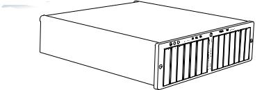
Introducing Xserve RAID
Your new Xserve RAID storage system provides high availability and scalable capacity and performance. Key features of Xserve RAID include
m3U enclosure (5.25 inches high)
mrack optimized
mdual independent RAID controllers, each with a minimum of 128 megabytes (MB) of RAM cache
mup to 14 hot-swappable ATA-100 Apple Drive Modules
mdual hot-swappable power supplies
mdual AC power connections
mdual hot-swappable cooling modules
mdual 2-gigabit (Gb) copper fibre channel ports, supporting point-to-point and switch fabric connections
mdual Ethernet ports for remote management of the system
mdual serial ports for uninterruptible power supply (UPS) communications
mMac OS X compatibility (version 10.2.4 or later)
mPCI host bus adapter card (sold separately) with dual fibre channel connectors for host system
moptional dual battery backup for controller cache
moptional service parts kit
moptional drive modules
The Xserve RAID system is designed to be mounted in a rack.
Important Two people are required to unpack, lift, or mount the Xserve RAID system in a rack. Do not attempt to lift or move the system without help from a second person.
9
Unpacking the System
The Xserve RAID system is shipped in special packaging to facilitate simple and safe removal from the carton. As noted previously, always work with a second person to lift or move the system.
Follow the steps below to open the carton and remove the system from its packaging.
1Locate a sturdy table, cart, or other flat surface on which to place the system. The destination surface should be as close as possible to the system’s carton.
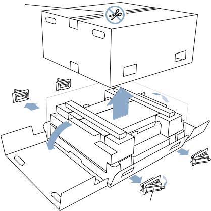
2With one person on each side of the carton, remove the four packing clips on each side of the carton by pulling the plastic tab at the end of each packing clip, then removing it from the carton.
3Cut the tape at the bottom of the carton.
Do not cut open the top of the box. The entire top comes off as a single piece.
Cut the tape that is on both sides on the
bottom of the box.
Remove the four plastic packing clips by snapping them open and pulling them out.
4Lift off the top section of the carton and set it aside.
The system is in the lower part of the carton, beneath two smaller boxes.
10 Chapter 1
5Remove the protective foam and the two boxes on top of the system.
6Fold back the plastic covering on the unit and fold down the carton at the front and back of the system.
7With one person at the front of the system and one at the back, carefully slide your hands between the system and its plastic cover where there are openings in the supporting foam, lift the system out of the carton, and put it on the table or other surface.
The unit is heavy. You must have two people lift it out of the box. With one person at each end, slide your hands underneath
the unit and over the plastic sheet in which it is wrapped. Working together, lift the unit carefully
using your knees, not your back.
8 |
Remove the protective film that covers the front of the system. |
9 |
If there is a plastic bracket that covers the center part of the system’s back panel, remove it. |
|
This bracket holds the components securely in place during shipping. |
10Remove the mounting hardware and power cords from the two separate boxes, as well as the system’s documentation.
11Write down the system serial number you see on the back panel. Also copy the Ethernet Media Access Control (MAC) number from the label on each control module (at the top and bottom in the center of the system). You will need these numbers when setting up and working with the monitoring and admin software.
Introducing Xserve RAID |
11 |
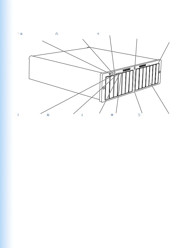
Your System at a Glance—Front Panel
|
Drive module |
System identifier |
Mute button |
Host activity |
Drive module |
|
|||||
|
|||||
|
lock and |
button and light |
|
lights |
activity and |
|
status light |
|
|
|
status lights |
Power supply |
Cooling system |
Temperature |
Controller |
Fibre channel |
Drive |
status light |
status light |
status light |
status light |
link lights |
modules |
12 Chapter 1
Drive module lock and lock status light
The lock secures the drive modules in the system. It can be locked and unlocked with the enclosure key supplied with the system (or a 3 mm. hex key).
System identifier button and light
The system identifier light turns on if a problem is detected. You can also turn it on manually by pressing the button. This indicator is useful for locating a particular unit in a rack with multiple systems. A duplicate is on the back panel. (See “Using Status Lights and Other Indicators” on page 46 for more information.)
—Mute button
Press to turn off the audible alarm that signals an error condition. (You can also turn off the alarm using the system’s monitoring and admin software.)
Fibre channel activity lights
Two vertical rows of 23 lights indicate fibre channel activity. (See “Using Status Lights and Other Indicators” on page 46 for more information.)
Drive module activity and status lights
Each drive module has two lights showing disk activity and drive status. See “Using Status Lights and Other Indicators” on page 46 for details.
Power supply status light
Indicates power supply operation: green is OK, red is failure. (See “Using Status Lights and Other Indicators” on page 46 for more information.)
Cooling system status light
Indicates cooling module operation: green is OK, red is failure.
Temperature status light
Indicates temperature status: green is OK, red is failure.
Controller status light
Indicates RAID controller operation: green is OK, red is failure. (See “Using Status Lights and Other Indicators” on page 46 for more information.)
Fibre channel link lights
Two lights indicate that a fibre channel connection is active for each RAID controller.
Drive modules
You can install up to 14 drive modules, in two groups of 7 modules each. You can remove and install these modules while the system is running. (See “Installing or Replacing an Apple Drive Module” on page 49 for more information.)
Introducing Xserve RAID |
13 |

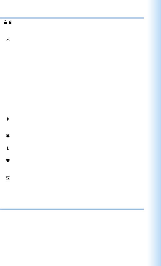
Your System at a Glance—Back Panel
System identifier |
Mute |
Controller |
RAID |
Cooling module |
Power |
button and light |
button |
status light |
controller |
status light |
button |
|
|
|
reset |
|
and light |
|
|
|
button |
|
|
Optional battery |
|
|
|
|
|
module bay (2) |
|
|
|
|
|
|
|
|
|
|
Ethernet port |
|
|
|
|
|
and status |
Power supply |
|
|
|
|
light (2) |
status lights |
|
|
|
|
|
Power supply (2) |
|
|
Fibre channel |
|
port and status |
Power socket (2) |
light (2) |
RAID controller module |
|
|
and status light (2) |
Cooling module (2) |
UPS interface port (2) |
14 Chapter 1
—
®
G
System identifier button and light
The system identifier light turns on if a problem is detected. You can also turn it on manually by pressing the button. This indicator is useful for locating a particular unit in a rack with multiple systems. A duplicate system identifier button and light are on the front panel. (See “Using Status Lights and Other Indicators” on page 46 for more information.)
Mute button
Press to turn off the audible alarm that signals an error condition. (You can also turn off the alarm using the system’s monitoring and admin software.)
RAID controller card, status lights, and reset button
The top controller manages the seven drive modules on the left side of the system (when facing the unit); the bottom controller manages the seven drive modules on the right. Use the reset button to restore the factory settings.
Cooling module and status light
A redundant, hot-swappable cooling module cools the system.
Power button and light
Press to turn on the system.
Battery module bay and cover
You can install optional battery modules to protect data in each RAID controller’s cache. A cover protects the two battery spaces if battery modules are not installed.
Power supply and status lights
A redundant, hot-swappable power supply provides power for the entire system. (See “Using Status Lights and Other Indicators” on page 46 for more information.)
Ethernet port and status light
Use the Ethernet port to connect to a network and manage the system remotely.
Power socket (in each power supply)
Connect the power cord here. The cord is held in place by a special clip.
UPS interface port
Connect an uninterruptible power supply (UPS) to this port.
Fibre channel port and status light
Use this port to connect each group of seven drive modules to a host bus adapter card located in a server or desktop system using a fibre channel cable.
Introducing Xserve RAID |
15 |
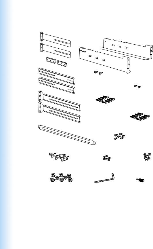
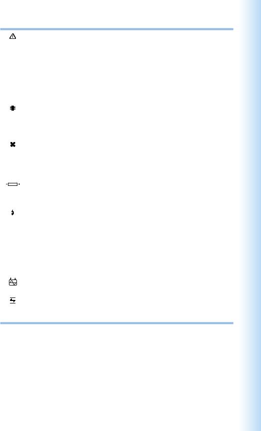
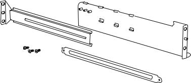
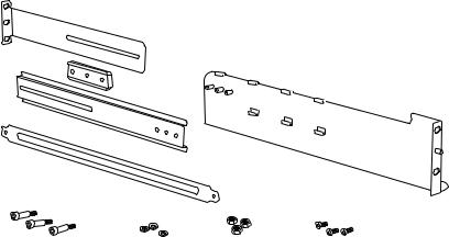
Your System at a Glance—Mounting Hardware
C |
|
|
E |
|
A2 |
|
|
|
Front mounting screws (2) |
A1 |
|
|
||
D |
|
|
|
Rear securing screws (2) |
|
|
Long screws (8 + extras) |
|
|
(10-32 x 3/4") |
|
|
B |
|
|
Long screws (8 + extras) |
|
|
|
(M6 x 20mm) |
Mounting template |
Short screws (6 + extras) |
|
|
(M5 x 6mm) |
|
Shoulder bolts (6 + extras) |
Washers (6 + extras) |
Nuts (6 + extras) |
(M5 x 14mm) |
(M5 x 1mm) |
(M5 x 4mm) |
Cage nuts + extras (if needed) |
Hex key wrench |
Enclosure key |
(M6) |
(5mm) |
(for security lock on front panel) |
16 Chapter 1

L-shaped brackets (A1 and A2)
Two large L-shaped brackets attach to the front of the four-post rack and support the system.
Bracket extenders for a 24to 29-inch rack (B)
These extenders attach to the brackets A1 and A2 and to the rear rail of the standard fourpost rack.
Bracket extenders for a 29to 36-inch rack (C and D)
Connect these two extenders and attach them to the brackets A1 and A2 and to the rear rail of the deep four-post rack.
Solid bar for connecting bracket extension pieces (E)
Use this bar to fasten extenders C and D for a deep rack.
Screws, nuts, washers, and hex key wrench for mounting the system
Use this hardware to secure the system to the rack and to connect the bracket extenders. See “Assemble the Brackets and Extenders” on page 27 for more information.
Mounting template
Use this template to help mount the brackets squarely to the rack. See “Assemble the Brackets and Extenders” on page 27 for more information.
Introducing Xserve RAID |
17 |

C H A P T E R
2
Preparing to Install Xserve RAID in a Rack
Before you install the system in a rack, carefully consider the placement of the unit in its rack and several other factors in the infrastructure that will keep the system operating efficiently.
Guidelines for Installation
To ensure safe and smooth operation of your Xserve RAID system, it’s essential that you choose an appropriate location for the system in its rack, and provide an appropriate operating environment and adequate power for all components in the rack. In addition, the system requires special handling because of its weight.
As you plan for installation, follow these guidelines to ensure that the system and its environment are safely and appropriately positioned for efficient operation and service.
Precautions for Handling the System
When configured with a full set of drive modules, the system weighs approximately 100 pounds. Take the following precautions to avoid problems or potential injury as you handle the Xserve RAID system.
mNever try to unpack, lift, or carry the system by yourself. Always have another person available to help move or lift it.
mPrepare a flat, sturdy surface before removing the system from its packaging. The table or cart that will hold the system should be as close as possible to the system’s carton.
mBoth people should follow these guidelines to lift or move the system: m Stand with your legs shoulder-width apart to maintain balance.
m Breathe deeply and tighten your stomach muscles to increase support for lifting. m Bend at your hips and knees, not at your waist.
m Use your leg muscles to lift.
19
mLift with a smooth motion; don’t jerk the load up or down.
mKeep the system close to your body and at waist level to lessen the load on your back.
mMaintain body alignment while lifting, so that your back, ears, shoulders, and hips are in line and your eyes and feet are facing the system.
mTo turn while holding the system, use your feet; don’t twist your back or torso.
Choosing the System’s Location in the Rack
The Xserve RAID system is designed for use in a four-post rack or cabinet. The rack must be 19 inches wide; it can vary in depth from 24 to 36 inches.
Important Do not try to install an Xserve RAID system in a two-post, or telco-style, rack. The system cannot be mounted safely in a two-post rack.
When determining where to place the system in a four-post rack, keep the following points in mind:
mBecause of the system’s weight, you may want to install it at or below the middle of the rack.
mMeasure the height needed in the rack (3U, or 5.25 inches at minimum).
mAlso measure the depth of the rack and the distance between the back panel of the system and the rear rail of the rack. This measurement will help you determine which of the bracket extenders to use when mounting the system in the rack.
mAir to cool the system flows from front to back. Be sure not to cover any of the ventilation holes in the front or back panels of the unit. Consistent airflow is essential to keep the system operating efficiently.
Remove the clear plastic film that covers the front so that airflow is not  restricted.
Do not block the air flowing through the unit.
mAllow room at the front and back of the system for service. Leave at least 36 inches clear in front of the system, so that you can easily swap drive modules and remove the system from the rack if necessary. Leave 24 to 30 inches clear behind the system to install or exchange components.
20 Chapter 2
mFor a rack that has multiple devices, you may want to prepare a list of all equipment in the rack and the requirements for each unit. Such a list should include the following information:
Power |
Clear area |
Height |
Temperature |
|
|
||||
Component needed |
front / back |
in rack |
range |
Other |
|
|
|
|
|
Xserve RAID
Server 1
Server 2
Managing Cables
Your Xserve RAID system uses three to six cables and two power cords. It’s a good idea to determine how these cables and cords will be arranged at the rear of the system and where the cables will be routed to connect to a host system. See “Connecting Xserve RAID to a Host System or Switch” on page 38 for details about connecting cables.
Rack Stability
The rack must be stable and strong enough to hold the Xserve RAID system and the other devices installed.
mCheck the documentation for the rack to make certain that it can support all its components.
Important Do not exceed the weight limit recommended for your rack.
mMake certain that all components are secured in the rack.
mWhen installing the system in a cabinet that has casters, verify that you can secure the
casters to keep the cabinet from moving as you mount the system. If the cabinet does not have a brake, make sure you can place the back of the cabinet against a wall as you install the system at the front.
Electrical Power
If you plan to install the system in a rack that contains other components, be sure that the circuitry and power connections are sufficient for the combined power needs of all components. To plan for safe and adequate power to the system, follow these guidelines:
mCheck the documentation for all components in the rack to determine their power requirements. Then make sure that the available power supply for the rack is sufficient for the planned components.
mIf you need assistance determining the power needs of the components in the rack, consult an electrical expert who is familiar with your facility.
Preparing to Install Xserve RAID in a Rack |
21 |
mIf there are devices in the system’s location that use large amounts of power, use surge protectors or power conditions as part of the installation.
Important When planning for electrical power, make sure you have more power than the total power requirements specified for all components. Also make certain that the power load is distributed evenly among circuits to the rack’s location. Consult an electrician or other expert if you need assistance with planning for the power needs of your components.
mMake sure that the power connections for the system and all other components are grounded (according to local and national standards). Consult an electrician if you need assistance with grounding.
mSee Appendix A, “Specifications,” on page 83 for more information about electrical power requirements for the system.
Operating Environment
The operating environment for the system’s rack must meet certain requirements:
mVerify that the temperature range of the rack’s location is within the limits established for the system and all other components.
mMake certain that the rack’s location has adequate ventilation to maintain the necessary temperature range. This is particularly important for a rack that is enclosed in a cabinet.
mIf multiple components are installed in the rack, consider additional cooling to assure efficient operation of the system and other equipment.
Security
To ensure the security of the system and rack, note the following:
mDetermine that the rack’s location is secure and that only authorized staff members or technicians can gain access to this location.
mIf using a cabinet that is not stored in a secure room, be sure that the cabinet can be locked securely and that access to it is limited to authorized staff.
mDevelop a plan for distributing and controlling keys to the rack’s location and access codes that will allow others to manage the system over the network. Keep the plan updated with names of key staff and relevant emergency information and procedures.
mStore a copy of essential system access information in a safe place away from the system’s location.
mStore the Xserve RAID documentation and related materials in a central location and inform key staff of that location. Also post electronic documents on network locations to which users of the system will have access.
22 Chapter 2
C H A P T E R
3
Mounting Xserve RAID in a Rack
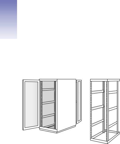
The Xserve RAID system is specifically designed for rack mounting. It is not designed for use as a desktop system. You can install the system in a four-post cabinet or rack that is 19 inches wide and between 24 and 36 inches deep. The system is 5.25 inches (3U) high.
Four-post cabinet rack
Four-post open rack
23
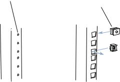
The brackets and screws necessary to attach the system to a four-post rack with threaded holes are included with your system. If your rack has square, unthreaded holes, you may need to insert cage nuts (some are provided with the system) into the appropriate holes before attaching the system to the rack.
Some racks have |
Other racks use various |
pre-threaded holes. |
types of removable |
|
cage nuts to secure |
|
equipment. |
Important Any rack used for Xserve RAID should meet the specifications of the American National Standards Institute (ANSI)/Electronic Industries Alliance (EIA) standard ANSI/EIA- 310-D-92, International Electrotechnical Commission (IEC) 297, and Deutsche Industrie Norm (DIN) 41494. See the documentation for the rack to determine whether it is compatible with these standards.
Getting Ready to Install the System
Before working with the system, mounting hardware, and rack, make the following preparations.
Important Check the rack’s documentation for any special requirements.
mArrange to work with another person as you prepare the system and install it in a rack.
mAssemble the tools, brackets, and fasteners you’ll need for the installation. (All except the screwdriver and pliers or wrench are provided with the system.) You will need
m a medium-sized Phillips screwdriver. If you have a power screwdriver, use it. m a pair of pliers or a small wrench
m the large L-shaped brackets and (depending on the depth of your rack) one or two bracket extenders
m the hardware supplied with the system to assemble the extenders and secure the system to the rack. See “Assemble the Brackets and Extenders” on page 27 for details.
24 Chapter 3
Note: Several sets of screws are provided with the system. These screws are designed for racks with prethreaded holes. Check the documentation for your rack and use the appropriate set of screws; most racks use one of the sizes. If screws are provided with your rack, you can use those as well.
mTo measure and mark the position of the system in the rack, you can use the metal mounting template that came with the system. You can also use a pen or pencil and some masking tape or similar tape to mark the position on the rack.
mClear a table, cart, or other flat surface near the rack. You’ll need to put the system on it temporarily during installation, and you can use it to lay out the brackets and screws you’ll use to attach the system to the rack.
Determine the Position for the System in the Rack
Review the guidelines for positioning the system in the rack (see “Choosing the System’s Location in the Rack” on page 20). Then follow these steps to measure and mark a specific location.
1Determine the exact position where you want to attach the bottom edge of the system and mark it on one side of the rack. To be sure there is room for the system at this position in the rack, the space available must be at least 5.25 inches from bottom to top.
The distance between holes may vary somewhat on racks made by different manufacturers.
2Use the template included with the system to mark the same spot on the other side of the rack.
3Measure the depth of the rack.
m If your rack is 24 to 29 inches deep, use brackets A1 and A2 and the medium-length extenders with a three-hole lip at one end (item B in the illustration below).
B
Short screws |
A1 and A2 |
Mounting template
Mounting Xserve RAID in a Rack |
25 |
mIf your rack is 29 to 36 inches deep, combine the shorter extender with a three-hole lip at the one end (item C in the illustration below) and the longest piece (with no lip; item D in the illustration), using the solid bar (item E in the illustration). This combination creates an extender long enough to reach the rear of a deep rack.
C
E
D
Mounting template
A1 and A2
Shoulder bolts |
Washers |
Nuts |
Short screws |
For a rack exactly 29 inches deep, try the A and B combination of bracket and extender; if that does not fit, use the A, C, D, and E combination.
Prepare the System for Installation
Follow these steps to prepare the system hardware for installation.
1With a second person, unpack the system from its carton and place it on the table or cart.
Follow the instructions in “Unpacking the System” on page 10.
2Write down the serial number on the system’s back panel and the two Ethernet MAC numbers on the RAID controller modules (at the center of the back panel).
You will need these numbers when you set up and use the Xserve RAID software.
Installing the System
To install the system in the rack, you m assemble the brackets
m attach the brackets to the rack
m rest the system on the brackets and secure it to the rack
26 Chapter 3
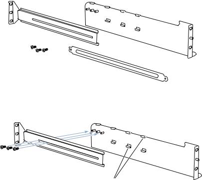
Assemble the Brackets and Extenders
Follow these steps to assemble the brackets and extenders for the depth of your rack.
For a Rack 24 to 29 Inches Deep
1Gather the two large brackets (items A1 and A2) and the two longer extenders (item B in the illustration below), along with the necessary screws:
m six short screws for assembling two brackets and extenders m four long screws for securing the brackets to the rack
m two mounting screws for attaching the system to the rack
B
Short screws |
A1 and A2 |
Mounting template
2Place the cut-out area of the extender (B) over the three posts that extend from the wider side of the bracket A.
B
Pass three of the short |
|
screws through the slot in part B and |
|
attach them to part A1 or A2. Tighten them securely. |
|
Make sure part B fits under the tabs on part A1 or A2. |
A1 or A2 |
3Fasten the bracket and extender together using three short screws and tighten the screws. Note that you can still slide the extender backward and forward.
Mounting Xserve RAID in a Rack |
27 |
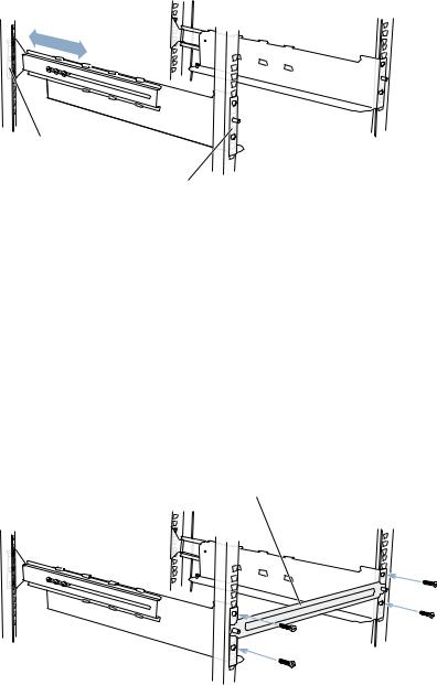
4Fit the assembled pieces into the rack so that the extender’s lip is near the rear rail and the lip of bracket A points toward the outer edge of the rack at the front rail.
Adjust the mounting
bracket assemblies to fit the rack. The flanges at both ends should be on the outside of the rack posts.
The orientation of bracket A determines on which side of the rack it belongs. The lower part of this L-shaped bracket faces inward (to support the system). The posts on the upper part of the bracket face outward and the extender is on the outside of the bracket. (In the illustration, bracket A1 goes on the left as you face the rack; A2 goes on the right of the system.)
5Hold one of the A brackets against one rail on the front of the rack at the position you marked, then place the metal template over the post on the front of the bracket.
6Have the other person hold the second A bracket at the position marked on the other front rail and place the metal template over the post on the front of the second bracket.
Important The brackets must be attached to the rails at a 90-degree angle to ensure that the Xserve RAID system is mounted securely. Use the template to guide you in attaching the brackets correctly.
Temporarily place the mounting template over the two posts on parts A1 and A2.
Attach each bracket assembly to the front  rack post with two of the screws provided.
Tighten the screws and then remove the template.
28 Chapter 3
Loading...