

Page 1
Service Source
Mac Pro (Early 2008)
Updated: 23 April 2008
© 2008 Apple Inc. All rights reserved.
Page 2

Apple Inc.
© 2008 Apple Inc. All rights reserved.
Under the copyright laws, this document may not be copied, in whole or in part, without the
written consent of Apple.
Every eort has been made to ensure that the information in this document is accurate. Apple is
not responsible for printing or clerical errors.
Apple
1 Innite Loop
Cupertino, CA 95014-2084
USA
+ 1 408 996 1010
www.apple.com
Apple, the Apple logo, and Mac Pro are trademarks of Apple Inc., registered in the U.S. and other
countries.
ii
Page 3

Mac Pro (Early 2008)
Contents
Basics
Overview 7
Identifying Mac Pro (Early 2008) Computers 8
Serial Number Location 8
Special Handling Instructions for Dual 3.2 GHz Conguration 9
Handling Instructions 9
Safety and First Aid Guidelines 10
Disposal Instructions 11
Take Apart
General Information 13
Orientation 13
Tools 13
Parts Requiring Enclosure Replacement 13
Note on Illustrations 13
Opening the Computer 14
Hard Drives 16
Optical Drive Carrier and Optical Drives 19
Memory (FB-DIMMs) and Memory Riser Cards 23
PCI Express/Graphics Card 27
Power Supply 32
Power Supply Fan 36
AirPort Extreme Card 41
Bluetooth Card 44
Battery 46
Processor Heatsink Cover 48
iii
Page 4

Front Fan Assembly 51
Mac Pro RAID Card and Battery 56
Memory Cage with Rear Fan 62
Northbridge Heatsink 68
Processor Heatsinks for 2.8 and 3.0 GHz Processors 71
Processor Heatsinks for 3.2 GHz Processors 78
Processors, 2.8 and 3.0 GHz 87
Processors, 3.2 GHz 92
Speaker Assembly 97
USB Cable 100
Logic Board 102
Front Panel Board 110
Power Button 114
AirPort Antenna Board with Cables 118
Optical Drive Power Cable 122
Optical Drive Data (Ribbon) Cable 125
Ambient Board 127
Ambient Board Cable 129
Bluetooth Antenna Board and Cable 131
Hard Drive Cable Harness 134
Hard Drive Temperature Sensor Cable 136
Hard Drive Temperature Sensor 138
Power Cable Harness 141
Troubleshooting
General Information 147
Memory 147
PCI Express Cards 149
Internal Cabling Matrix 149
iv
Page 5

Thermal Calibration 151
Resetting the Logic Board 152
Power-On Self Test: RAM and Processor Verication 153
Diagnostic LEDs 154
Power Supply Verication 159
Mac Pro Firmware Updates 159
Processor Heatsink and Processor Visual Inspection Instructions 161
Symptom Charts 164
How to Use the Symptom Charts 164
Startup Failures 164
Fans 167
AirPort Extreme Card 168
Bluetooth Card 169
Other Failures 169
Upgrades
AirPort Extreme Card 173
PCI Express/Graphics Card 176
Views
Exploded Views 181
External Views 183
Screw Matrix 185
v
Page 6

Service Source
Basics
Mac Pro (Early 2008)
© 2008 Apple Inc. All rights reserved.
Page 7
Overview
The Mac Pro (Early 2008) computer features single and dual quad-core Intel 2.8 GHz processors
and dual quad-core Intel 3.0 and 3.2 GHz processors. New CTO options include a 1 TB SATA hard
drive and a 300 GB SAS drive.
Note: The 3.2 GHz conguration of the Mac Pro (Early 2008) computer uses a special coating
on the processor heatsink and processor as was used on the Mac Pro (8x) processor heatsink
and processor. The other 2.8 and 3.0 congurations of the Mac Pro (Early 2008) do not use this
coating.
Mac Pro (Early 2008)) Basics 7
Page 8
Identifying Mac Pro (Early
2008) Computers
To identify a Mac Pro (Early 2008) computer, check the conguration code on the computer’s
conguration label, which is located on the computer’s back panel directly below the video ports.
See the following section “Serial Number Location.”
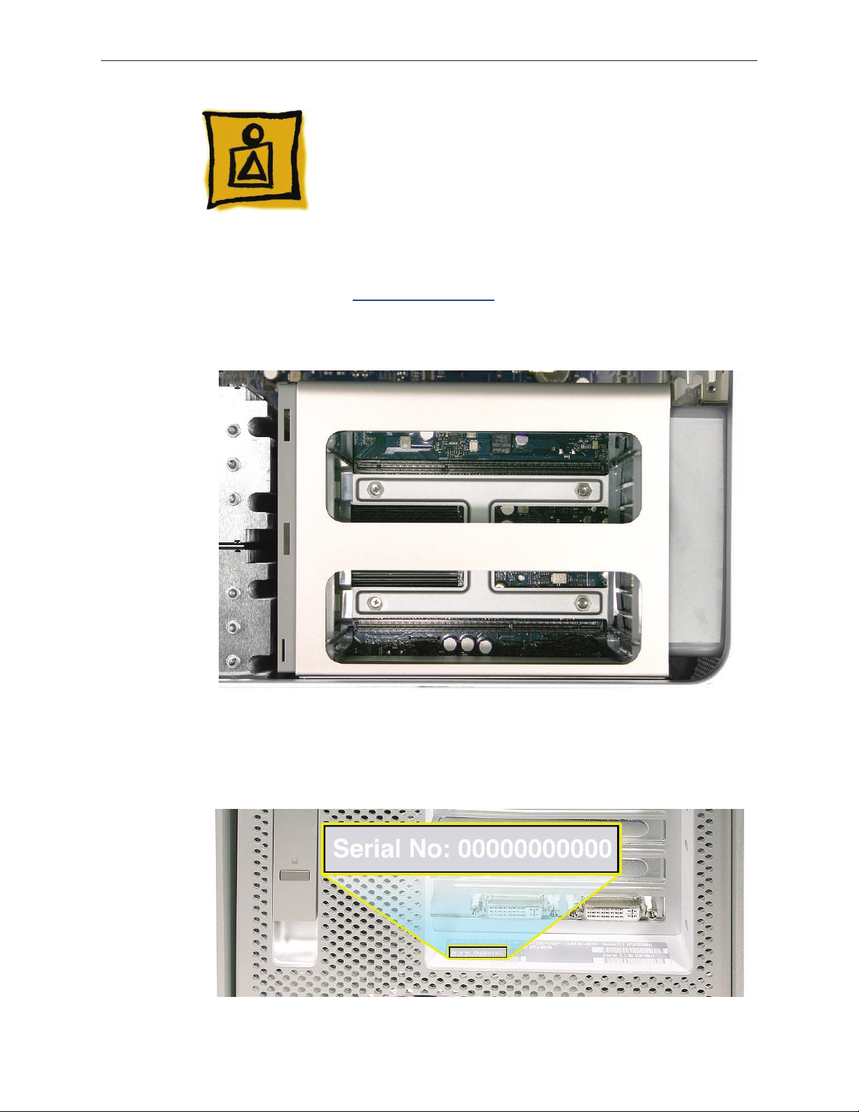
One other quick way to identify the computer is to open the side panel and inspect the memory
cage. The Mac Pro (Early 2008) memory cage has a cross bar and looks like the following:
Serial Number Location
The Mac Pro (Early 2008) serial number is located on the conguration label, directly below the
conguration description.
Mac Pro (Early 2008)) Basics 8
Page 9
Special Handling Instructions
for Dual 3.2 GHz Conguration
The dual 3.2 GHz conguration of the Mac Pro (Early 2008) uses a special coating on the
processor heatsink and processor to manage the temperature in the computer. To ensure proper
handling and disposal of this material, please read the following information.
Important: These instructions apply only to the dual 3.2 GHz conguration.
Handling Instructions
Use these guidelines when handling the Mac Pro (Early 2008) processor heatsink and processor:
General
Wear disposable nitrile or latex gloves when handling the processor heatsink and processor.•
Avoid touching the silver coating on the underside of the heatsink and the top of the •
processor.
Use care when removing the heatsink from the computer. As much as possible, lift the •
heatsink straight up o the processor.
Use care when removing the processor from the logic board. Lift the processor out of the •
processor holder by inserting a nger or atblade screwdriver in the notch at the front of the
holder. Hold the processor only by the edges.
When installing a replacement heatsink or processor, remove the protective cover from •
the new heatsink or processor and transfer it to the defective heatsink or processor before
packaging it for return to Apple.
Timing
When removing or replacing the heatsink and/or processor, do not allow the heatsink to be •
separated from the processor for more than 30 minutes. The silver coating on the heatsink
and processor degrades with exposure to air; more than 30 minutes exposure could result
in damage to the computer and a repeat, multi-part repair. Reassemble the computer while
waiting for any new parts to arrive.
When installing a new logic board, use care in transferring the heatsinks and processors to •
the new board. Do not allow the heatsinks and processors to be separated from the board
or from each other for more than 30 minutes. Reassemble the computer while waiting for a
new logic board to arrive.
Visual Inspection
Always make a visual inspection of a new processor or heatsink before installing it in the •
computer.
Always make a visual inspection of both existing processors and heatsinks before •
transferring them to a new logic board.
Mac Pro (Early 2008)) Basics 9
Page 10

See “• Processor Heatsink and Processor Visual Inspection Instructions” in the
Troubleshooting chapter for more information.
Krytox Thermal Grease
To ensure a proper seal between the heatsink and processor, a bead of Krytox grease rims •
the gasket on the underside of the heatsink. Replacement heatsinks come with the grease
already applied.
Use the following guidelines for when to reapply Krytox grease to the heatsink. (Refer •
to “Processor Heatsinks for 3.2 GHz Processors” in the Take Apart chapter for detailed
instructions on how to apply or clean o the grease.)
In most cases, you do not need to reapply Krytox grease when installing a new processor or when transferring processors and heatsinks to a replacement logic board.
If you are installing a new heatsink , remove any residual grease from the outer edges of the processor. Do not apply new grease to the heatsink or processor, as the heatsink
comes with the full capacity of grease applied.
For more detailed information, refer to “Processor Heatsinks for 3.2 GHz Processors” and
“Processors, 3.2 GHZ” in the Take Apart chapter.
Safety and First Aid Guidelines
Below is a summary of safety and rst aid measures for exposure to the coating on the processor
heatsink and processor or the Krytox grease used in sealing the processor heatsink to the
processor. For complete instructions, refer to the specic Material Safety Data Sheets (MSDS)
included with the replacement parts.
Safety
Avoid contact with eyes.
Avoid contact with skin.
Wash thoroughly after handling.
Do not store or consume food, drink, or tobacco in areas where they may become
contaminated with the material.
First Aid
Eyes: Immediately ush with plenty of water. If wearing contact lenses, after initial ushing,
remove contact lenses and continue to ush for 15 minutes. Have eyes examined by a
medical professional if irritation persists.
Skin: Wash skin with soap and running water. The recommended ushing is 15 minutes if
pain or irritation occurs. Remove and wash contaminated clothing. Seek medical attention if
irritation or redness develops.
Inhalation: Remove to fresh air. If not breathing, give articial respiration. If breathing is
dicult, give oxygen. Call a physician.
Mac Pro (Early 2008)) Basics 10
Page 11

Ingestion: Do not induce vomiting. Contaminated individual should immediately be given
two glasses of water. Never give anything by mouth to someone who is unconscious, having
convulsions, or unable to swallow. Call a physician.
Disposal Instructions
Place all disposable materials used in removing or replacing a processor heatsink or processor
inside the resealable plastic bag included with the replacement module. (Disposable materials
include such items as protective gloves, alcohol wipes, lint-free cleaning cloths, Krytox grease
and syringe, and heatsink gasket.) Pack this bag along with the failed module in the box that the
replacement module came in, and return the box to Apple.
Mac Pro (Early 2008)) Basics 11
Page 12

Service Source
Take Apart
Mac Pro (Early 2008)
© 2008 Apple Inc. All rights reserved.
Page 13

General Information
Orientation
For most take-apart procedures, it is recommended that you lay the computer on its side before
removing or installing the part. For proper operation, however, Apple recommends that the
unit be run in the upright position. The computer should never be operated on its side with the
access panel facing down.
Tools
The following tools are required to service all congurations of the computer:
Long-handled magnetized Phillips #1 screwdriver•
Long-handled magnetized 3 mm athead hex screwdriver•
Short-handled, magnetized 2.5 mm hex wrench•
Flat-blade screwdriver•
Magnetized jewelers Phillips #1 screwdriver •
Magnetized jeweler’s Phillips #0 screwdriver•
Jeweler’s at-blade screwdriver•
Needlenose pliers•
Scissors or wire cutters•
Nylon probe tool (black stick)•
Thermal grease kit (Apple part number 076-1258)•
Tape (for temporarily holding cables out of the way)•
Small mirror (for seeing small boards inside the enclosure)•
Soft cloth (for protecting the enclosure from scratches)•
Parts Requiring Enclosure Replacement
The following are not separate, orderable parts. To replace them, you must replace the enclosure.
Media shelf•
Rear panel latch•
Note on Illustrations
Because a pre-production model was used for the illustrations in this manual, you may notice
small dierences between the image pictured and the computer you are servicing.
Mac Pro (Early 2008) Take Apart — General Information 13
Page 14

Opening the Computer
Tools
No tools are required for this procedure.
Preliminary Steps
Shut down the computer. 1.
Warning: Always shut down the computer before opening it to avoid damaging its internal
components or the components you are installing. Do not open the computer or attempt to
install items inside it while it is on.
Wait 5 to 10 minutes to allow the computer’s internal components to cool. 2.
Warning: After you shut down the system, the internal components can be very hot. You
must let the computer cool down before continuing.
Unplug all external cables from the computer except the power cord.3.
Touch the metal PCI access covers on the back of the computer to discharge any static 4.
electricity from your body.
Important: Always discharge static before you touch any parts or install any components
inside the computer. To avoid generating static electricity, do not walk around the room until
you have nished working and closed the computer.
Unplug the power cord. 5.
Warning: To avoid damaging its internal components or the components you want to
install, always unplug the computer before attempting any take-apart procedure.
Put on an ESD wrist strap.6.
Mac Pro (Early 2008) — Opening the Computer 14
Page 15
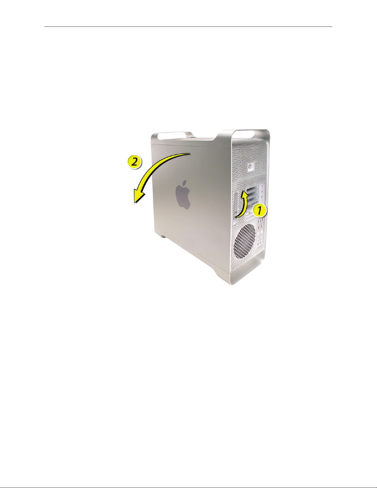
Procedure
Hold the side access panel and lift the latch on the back of the computer. 1.
Warning: The edges of the access panel and the enclosure can be sharp. Be very careful
when handling them.
Remove the access panel and place it on a at surface covered by a soft, clean cloth. 2.
Replacement Note: Make sure the latch is in the up position before replacing the access
panel. If the latch is down, the access panel will not seat correctly in the enclosure.
Mac Pro (Early 2008) — Opening the Computer 15
Page 16

Hard Drives
The Mac Pro (Early 2008) computer can accommodate four hard drives in its four internal hard
drive bays. In most congurations, a single SATA hard drive occupies the far left bay (bay 1). You
can install additional SATA drives in the second, third, and fourth hard drive bays. Or you can
install up to four SAS drives.
The hard drives must meet the following specications:
Type: Serial Attached SCSI (SAS) or Serial ATA (SATA) 3 Gb/s•
Width: 3.9 inches (102 mm)•
Depth: 5.7 inches (147 mm)•
Height: 1.0 inch •
Important: To install SAS drives in a Mac Pro (Early 2008) computer, you must also install the
optional Mac Pro RAID Card.
Tools
The only tool required for this procedure is a Phillips #1 screwdriver.
Preliminary Steps
Before you begin, open the computer, and lay it on its side with the access side facing up.
Important: Make sure the latch on the back panel is in the up position. When the latch is down,
the hard drives and carriers are locked in place and you will not be able to remove them.
Mac Pro (Early 2008) Take Apart — Hard Drives 16
Page 17

Part Location
Procedure
Make sure the latch on the back panel is up, so that the drives and carriers are unlocked.1.
Pull the hard drive out of the drive bay. 2.
Mac Pro (Early 2008) Take Apart — Hard Drives 17
Page 18
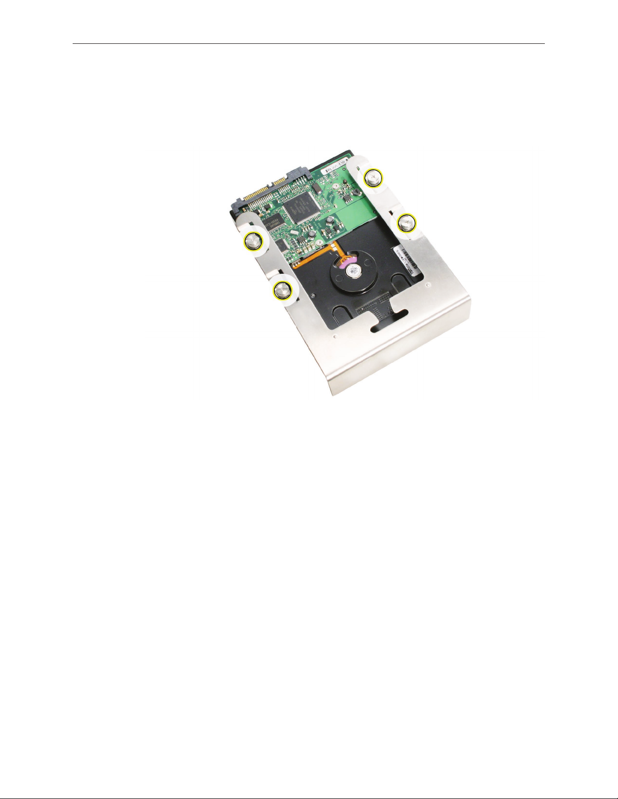
If you are replacing the hard drive with a new drive, remove the four screws that mount the 3.
drive to the carrier and mount the new drive in the carrier.
Important: Hold the drive by its sides. Be careful not to touch the printed circuit board on
the bottom of the drive.
Replacement Note: Slide the carrier and drive over the guides and into the drive bay, until you
feel the drive snap into place.
Note: If you install a new (replacement) drive, format it by following these steps:
Open Disk Utility and select the drive in the list to the left. 1.
Note: If you are formatting the primary drive, use the Disk Utility program on the Install Disk.
Click on the Partition tab.2.
Click on “Options” and verify GUID is selected if this is a bootable drive.3.
Apply the change by clicking on the “Partition” button.4.
Mac Pro (Early 2008) Take Apart — Hard Drives 18
Page 19
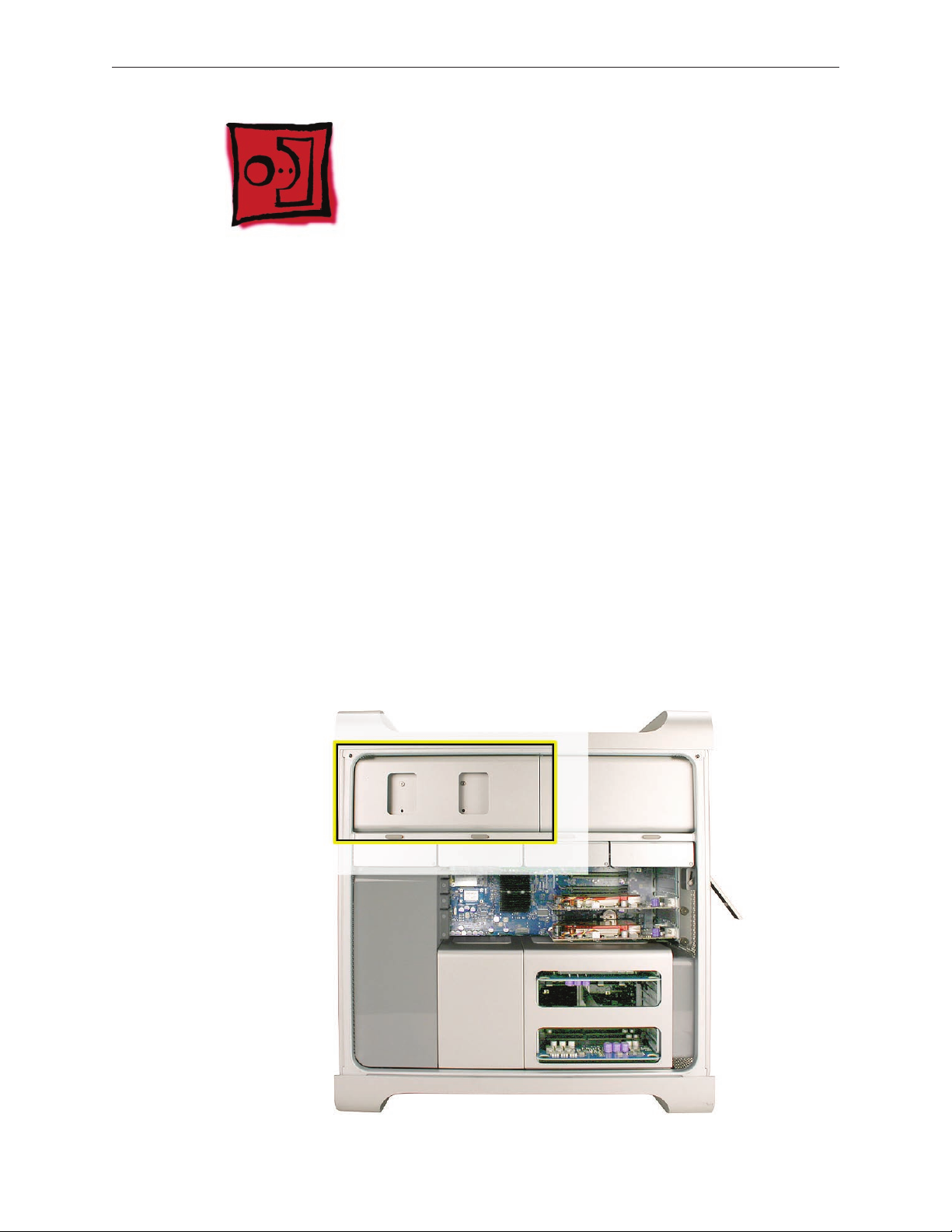
Optical Drive Carrier and Optical Drives
The Mac Pro (Early 2008) computer can accommodate two optical drives in the optical drive bay.
If the computer has only one optical drive, it is installed in the top position.
Note: To eject the drives, use the following:
Top drive: Press the Eject key.•
Bottom drive: Press the Option and Eject keys.•
Tools
The only tool required for this procedure is a Phillips #1 screwdriver.
Preliminary Steps
Before you begin, open the computer, and lay it on its side with the access side facing up.
Important: Make sure the latch on the back panel is in the up position. When the latch is down,
the optical drives and carrier are locked in place and you will not be able to remove them.
Part Location
Mac Pro (Early 2008) Take Apart — Optical Drive Carrier and Optical Drives 19
Page 20
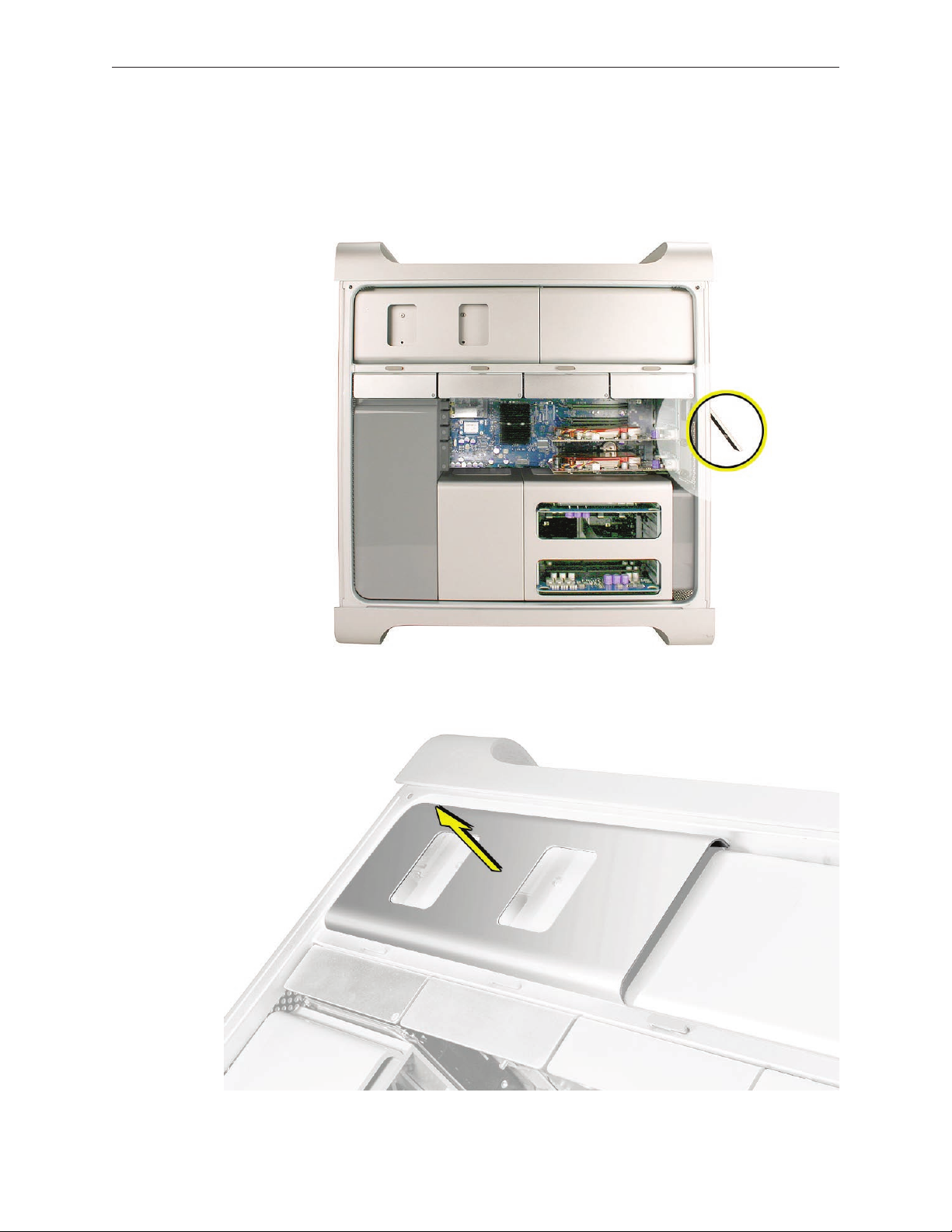
Procedure
Removing the Optical Drive Carrier and Optical Drives
Make sure the latch on the back panel is up, so that the drives and carriers are unlocked. 1.
Pull the optical drive carrier part way out of the computer. 2.
Mac Pro (Early 2008) Take Apart — Optical Drive Carrier and Optical Drives 20
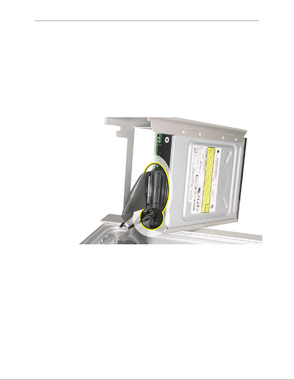
Page 21
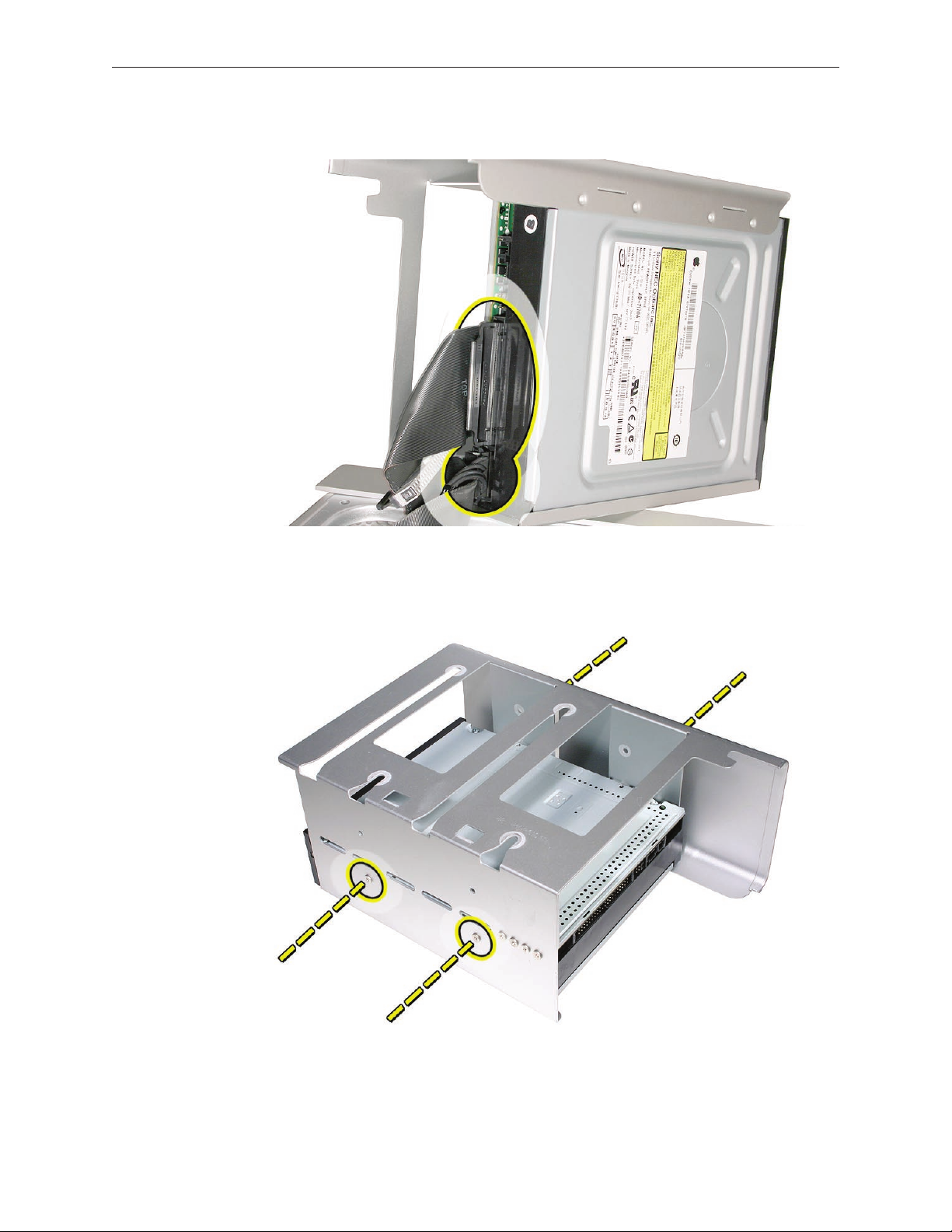
Disconnect the power and ribbon cables from the optical drive(s) and remove the carrier. 3.
If you are replacing the optical drive with a new optical drive, do the following:4.
Remove the four mounting screws and remove the optical drive from the carrier.•
Use the four screws to mount the replacement drive in the carrier.•
Note: If you are adding a second drive to the carrier, use the four screws stored on the back of
the drive carrier to secure the drive to the carrier.
Mac Pro (Early 2008) Take Apart — Optical Drive Carrier and Optical Drives 21
Page 22
Replacing the Optical Drive Carrier and Optical Drives
Important: Use the original Apple cables that came with the computer when you install or
replace the optical drives. If just one optical drive is installed, tuck the cables for the second drive
out of the way.
Attach the power and ribbon cables to the back of the drive(s). 1.
Important: Attach the connector on the end of the optical drive ribbon cable and the
connector in the middle of the optical drive power cable to the top drive. If there is a second
drive in the carrier, attach the remaining optical drive ribbon and power connectors to the
bottom drive.
Slide the optical drive carrier over the guides and into place in the optical drive bay. 2.
Important: Be very careful not to catch the cables under the carrier as you slide it into the
bay.
Mac Pro (Early 2008) Take Apart — Optical Drive Carrier and Optical Drives 22
Page 23
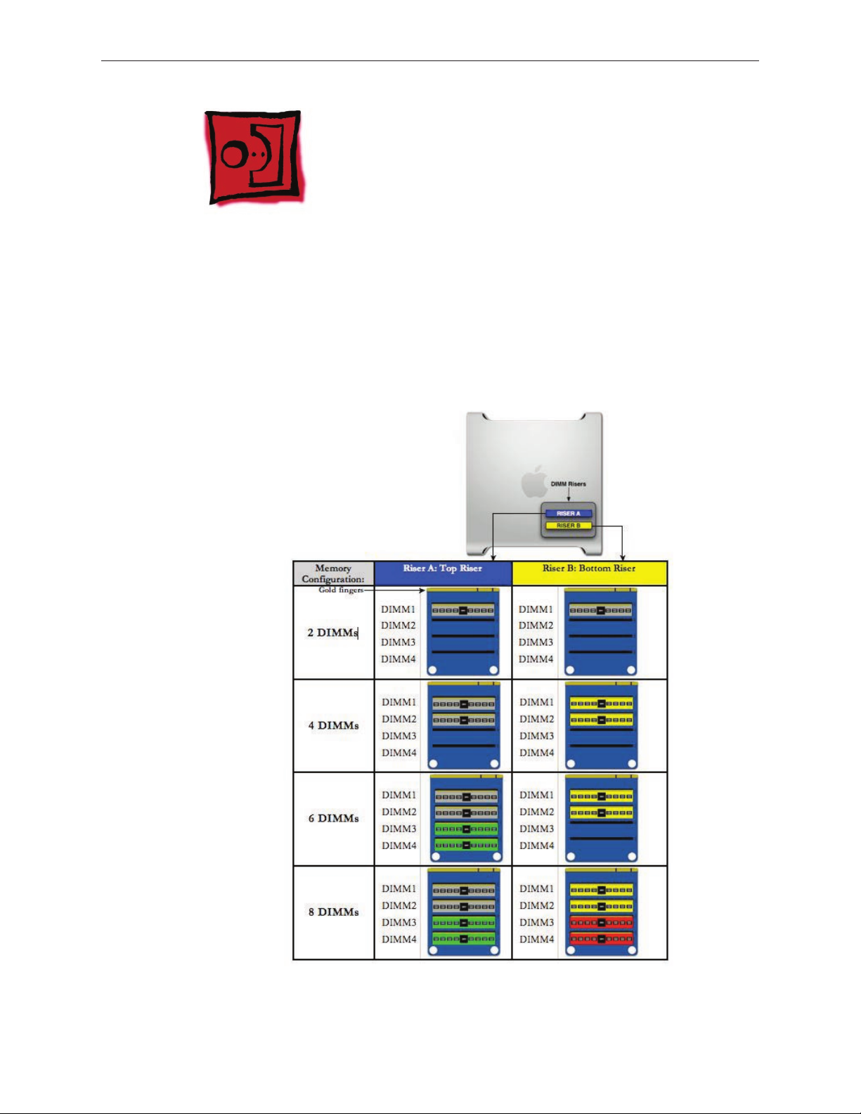
Memory (FB-DIMMs) and Memory Riser Cards
The Mac Pro (Early 2008) computer has two memory riser cards with a total of 8 memory slots.
On each card, the slots are arranged as two banks of two slots each. The computer comes with
a minimum of 2 GB of memory, installed as a pair of 1 GB fully buered, dual inline memory
modules (FB-DIMMs) in two of the DIMM slots. Additional pairs of 1 GB, 2 GB, or 4 GB FB-DIMMs
can be installed in the open DIMM slots, as illustrated below. Maximum memory is 32 GB.
DIMMs must be installed as pairs of identical size and type, from the same vendor. In the
illustration below, like-colored DIMMs must match.
Mac Pro (Early 2008) Take Apart — Memory (DIMMs) and Memory Riser Cards 23
Page 24
DIMMs for Mac Pro (Early 2008) must t these specications:
800 MHz, DDR2, FB-DIMMs•
72-bit wide, 240-pin modules•
36 memory ICs maximum per DIMM•
Error-correcting code (ECC)•
Memory from older Macintosh computers is not compatible with Mac Pro (Early 2008).
Important: For proper operation of Mac Pro (Early 2008) computers, Apple recommends using
only Apple-approved Mac Pro (Early 2008) FB-DIMMs. Refer to GSX for Apple FB-DIMMs service
part numbers.
Tools
No tools are required for this procedure.
Preliminary Steps
Before you begin, open the computer, and lay it on its side with the access side facing up.
Warning: Always wait 5–10 minutes for the computer to cool down before you remove or install
memory. The DIMMs may be very hot.
Part Location
Mac Pro (Early 2008) Take Apart — Memory (DIMMs) and Memory Riser Cards 24
Page 25
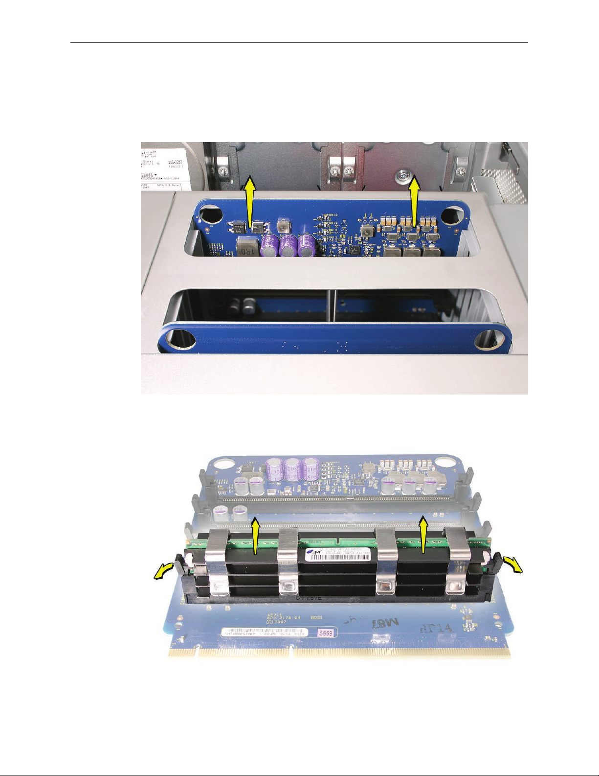
Procedure
Holding the memory riser card by the two nger holes, pull it out of the memory cage and 1.
place the card DIMM side up on a soft, clean cloth.
Open the ejectors on the DIMM slot by pushing them out to the sides, and remove the 2.
DIMM from the riser card.
Mac Pro (Early 2008) Take Apart — Memory (DIMMs) and Memory Riser Cards 25
Page 26
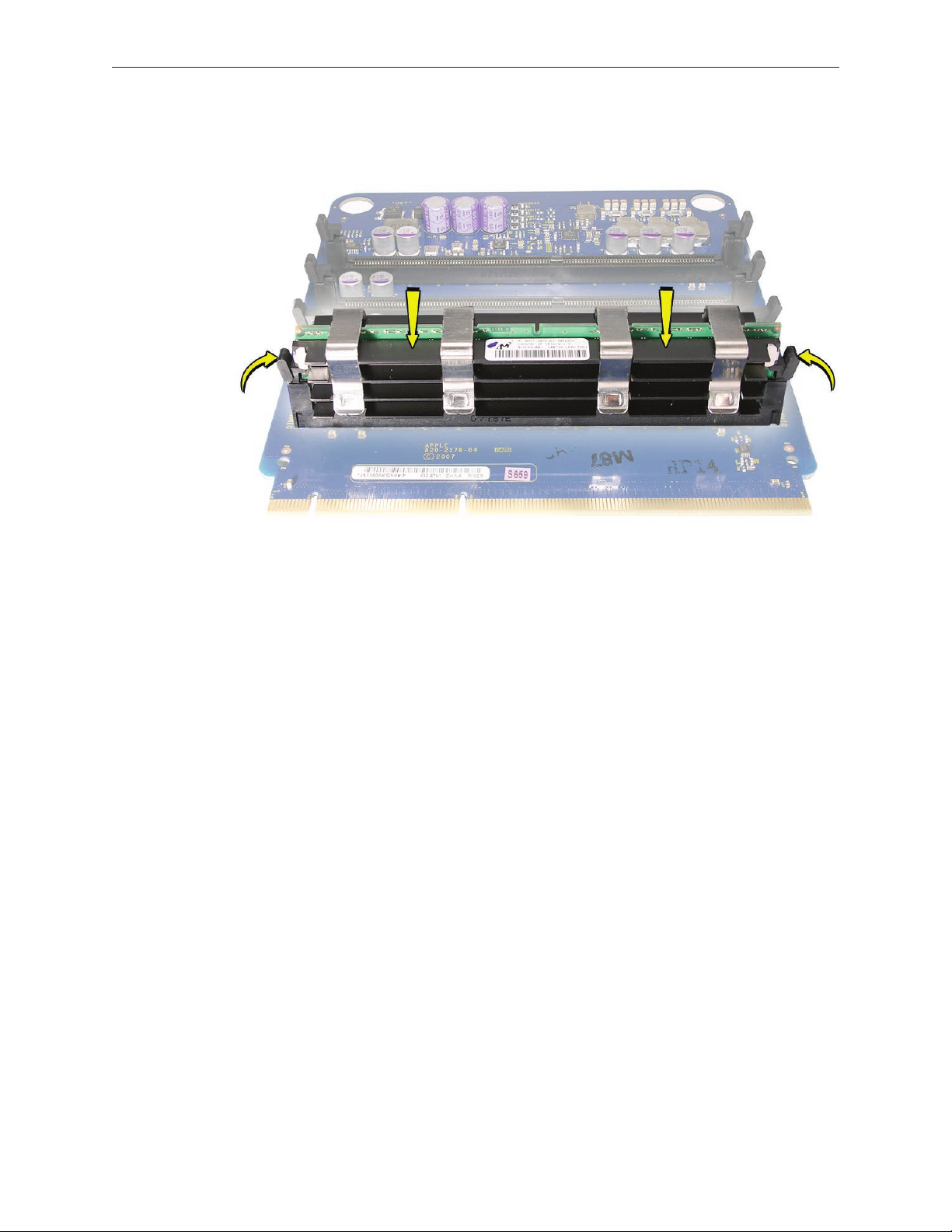
Replacement Note: Align the DIMM in the slot on the riser card and push both ends of the
DIMM down until the ejectors snap back up into place.
Warning: FB-DIMMs carry heatsinks on either side of the DIMM. Never attempt to remove the
heatsinks from the DIMMs. Doing so could damage the DIMM.
Mac Pro (Early 2008) Take Apart — Memory (DIMMs) and Memory Riser Cards 26
Page 27
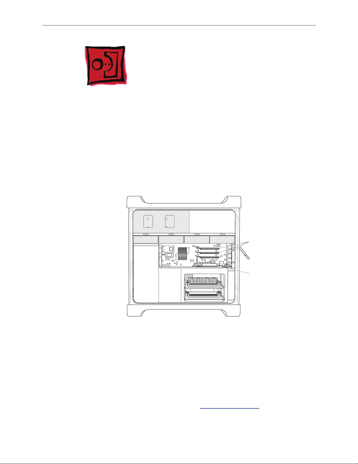
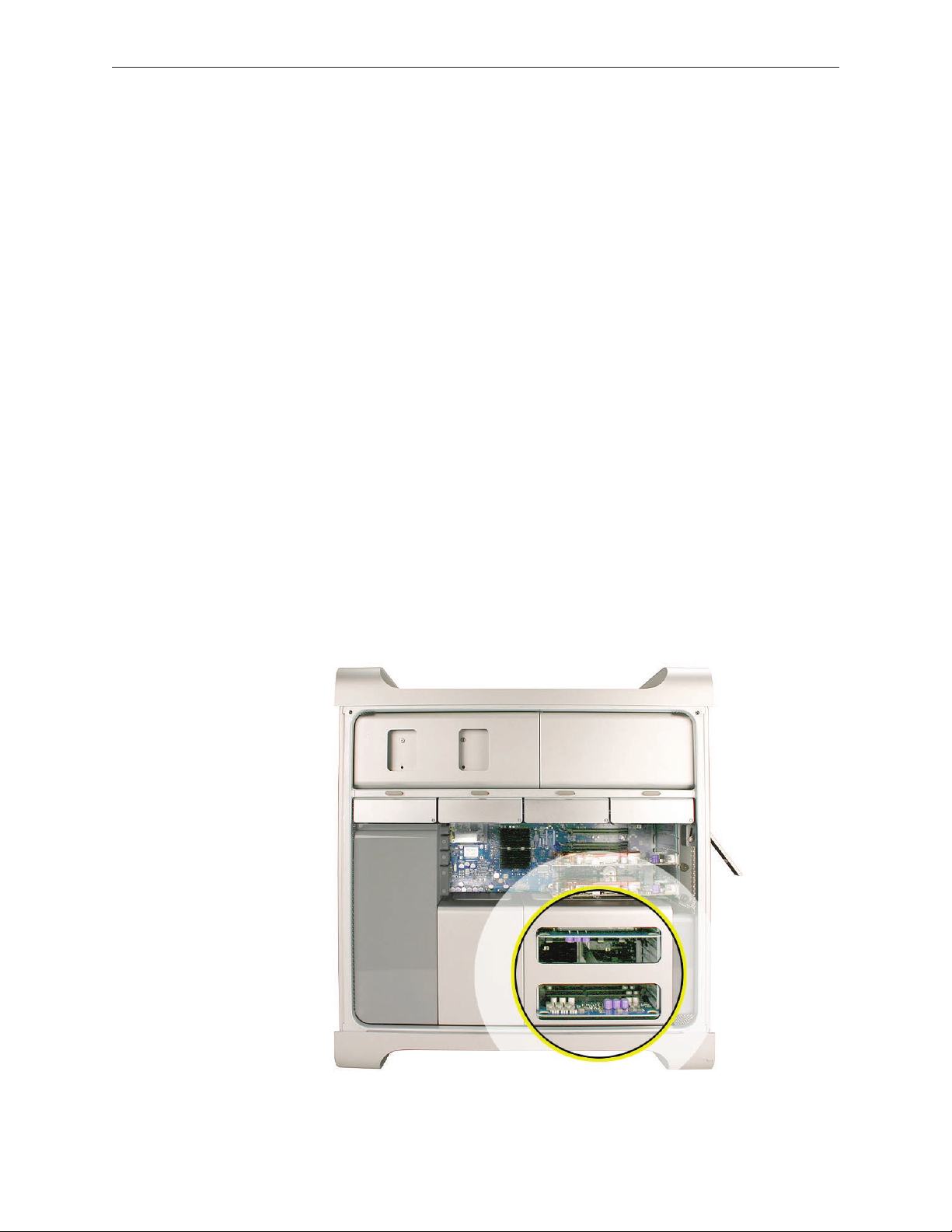
PCI Express/Graphics Card
Slot 1: Double-wide
PCI Express graphics
(graphics card installed)
Slots 2–4: PCI Express
The Mac Pro (Early 2008) logic board includes one double-wide PCI Express graphics slot and
three PCI Express expansion slots, for a total of four slots. The computer comes with a graphics
card installed in slot 1. You can install additional PCI Express graphics and expansion cards in the
remaining three PCI Express expansion slots.
Important: Graphics cards from previous Power Mac G5 models are not compatible with Mac
Pro (Early 2008) models. In addition, Mac Pro (Early 2008) graphics cards are not compatible with
previous models.
Important: Combined maximum power consumption for all four PCI Express slots must not
exceed 300 W.
Tools
The only tool required for this procedure is a Phillips #1 screwdriver.
Preliminary Steps
Before you begin, open the computer, and lay it on its side with the access side facing up.
Note: You may also nd it helpful to remove the hard drives and carriers and any adjacent PCI
Express cards before beginning this procedure.
Mac Pro (Early 2008) Take Apart — PCI Express/Graphics Card 27
Page 28
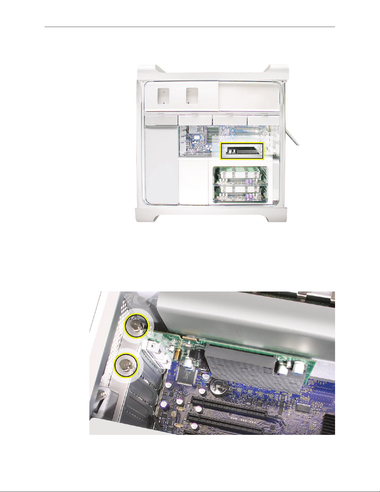
Part Location
Procedure
This procedure explains how to remove a standard card and a card that includes a booster cable.
Before you can remove either type of card, however, you must rst loosen the two captive screws
that secure the PCI bracket to the enclosure and remove the bracket.
Mac Pro (Early 2008) Take Apart — PCI Express/Graphics Card 28
Page 29
Warning: When removing or installing a card, handle it only by the edges. Do not touch its
connectors or any of the components on the card. Lift the card straight out from the connector
to remove it, and insert it straight into the connector to install it. Do not rock the card from side
to side and don’t force the card into the slot. Once the replacement card is installed, pull on it
gently to check that it is properly connected.
Standard Card
Release the small locking clip at the front of the card’s logic board connector by pushing the 1.
clip up toward the media shelf.
Holding the card by the top corners, pull up the card and remove it from its expansion slot.2.
Replacement Note: Align the card’s connector with the expansion slot and press until the
connector is inserted all the way into the slot. If you’re installing a 12-inch card, make sure the
card engages the appropriate slot in the PCI card guide.
Don’t rock the card from side to side; instead, press the card straight into the slot. •
Don’t force the card. If you meet a lot of resistance, pull the card out. Check the connector •
and the slot for damage or obstructions, then try inserting the card again.
Pull the card gently to see if it is properly connected. If it resists and stays in place and its •
gold connectors are barely visible, the card is connected.
Mac Pro (Early 2008) Take Apart — PCI Express/Graphics Card 29
Page 30
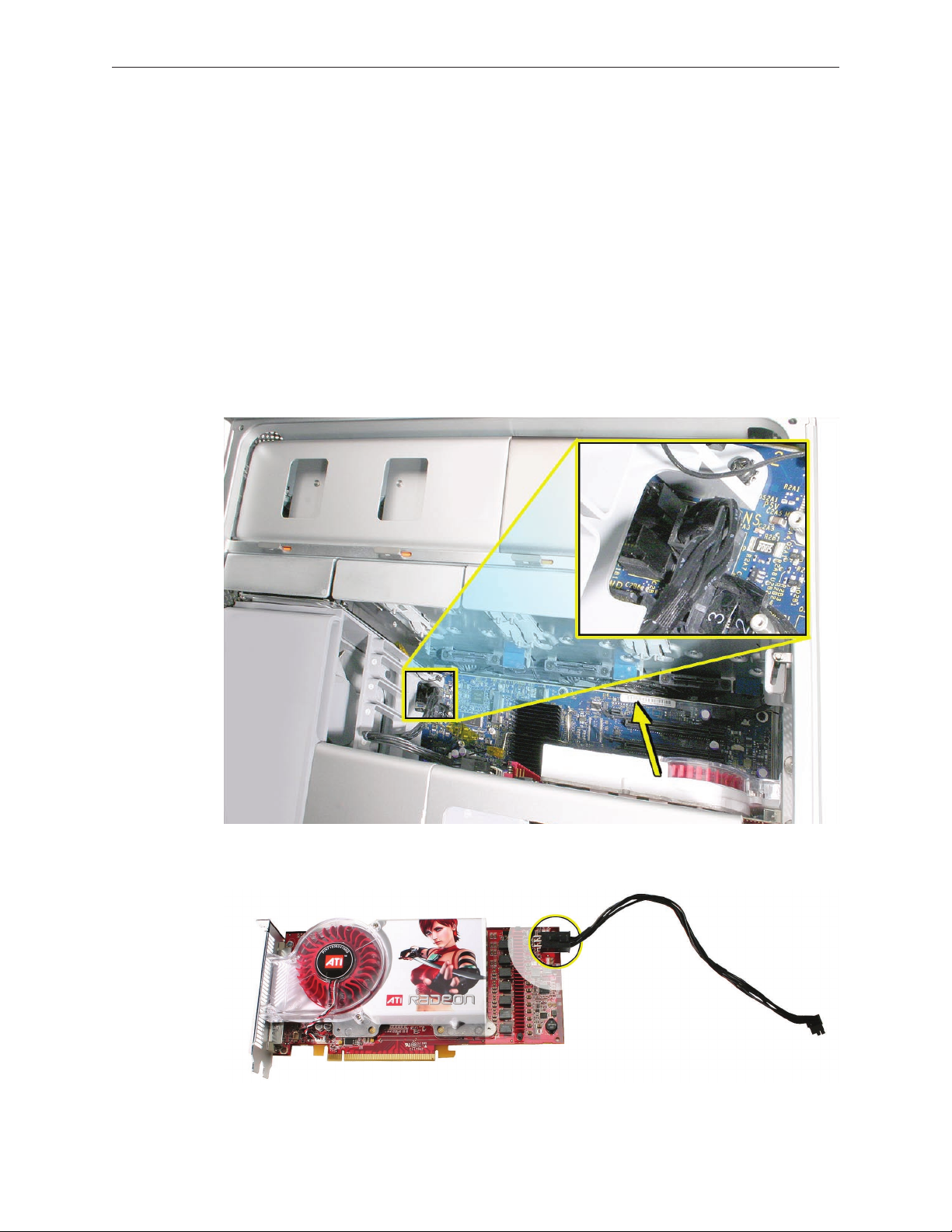
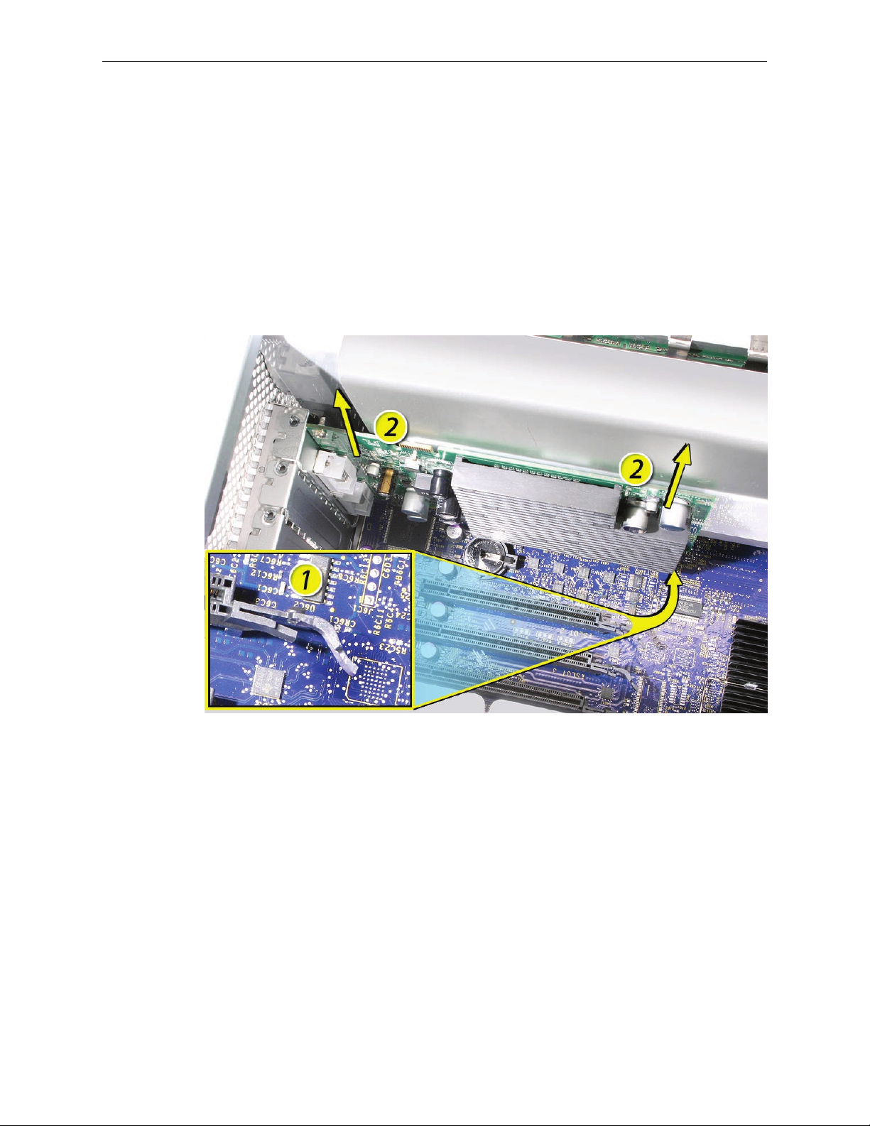
Card with Booster Cable
Some graphics cards require either one or two booster cables connecting the card to the
auxillary power connectors on the logic board.
Note: The graphics card NVIDIA GeForce 8800 GT requires one booster cable; the graphics card
NVIDIA Quadro FX 5600 requires two booster cables.
Disconnect the booster cable(s) from the logic board.1.
Release the small locking clip at the front of the card’s logic board connector by pushing the 2.
clip up toward the media shelf.
Holding the card by the top corners, gently pull up the card and remove it from its 3.
expansion slot.
If you are replacing a booster cable with a new one, disconnect the cable from the card.4.
Mac Pro (Early 2008) Take Apart — PCI Express/Graphics Card 30
Page 31

Replacement Note for Card Using One Booster Cable: Be sure to connect the card’s booster
cable to the correct auxillary power connector on the logic board. Connect the booster cable for
a card in PCI slot 1 to the lower connector. Connect the booster cable for a card in PCI slot 2 to
the upper connector.
Replacement Note for Card Using Two Booster Cables: Connect both cables to the two
auxillary power connectors.
Mac Pro (Early 2008) Take Apart — PCI Express/Graphics Card 31
Page 32

Power Supply
Tools
The only tools required for this procedure are a magnetized 2.5 mm hex wrench and a long-
handled, magnetized Phillips #1 screwdriver.
Preliminary Steps
Before you begin, open the computer, lay it on its side with the access side facing up, and remove
the following:
Hard drives and hard drive carriers in drive bays 3 and • 4
Optical drive carrier and optical drive• s
Any PCI Express cards that block access to the power supply mounting screw• s
Part Location
Mac Pro (Early 2008) Take Apart — Power Supply 32
Page 33

Procedure
Using a Phillips screwdriver, remove the two mounting screws on the power supply cable 1.
cover located at the back of the optical drive bay.
Slide the cover toward the top of the enclosure, tilt it up until the two tabs on the cover clear 2.
the slots in the media shelf, and remove the cover from the enclosure.
Replacement Note: Replace the cover at an angle so that the tabs engage with the slots in
the media shelf. Then lower the cover into place.
Mac Pro (Early 2008) Take Apart — Power Supply 33
Page 34

Using a short-handled, magnetized 2.5 mm hex wrench, remove the four power supply 3.
mounting screws from the bottom of the media shelf.
Release the four power supply cables from their hook-and-loop fasteners on the enclosure.4.
Depress the locking latch on each cable connector and disconnect the four power supply 5.
cables from the four connectors on the power harness cable.
Mac Pro (Early 2008) Take Apart — Power Supply 34
Page 35

Slide the power supply toward the front of the computer. 6.
Lift the power supply and cables out of the enclosure. 7.
Replacement Note: When replacing the power supply, be sure to slide it toward the back of the
computer as far as possible. The power receptacle must align with the opening in the enclosure’s
back panel and the four screw holes in the power supply must align with the screw holes in the
media shelf.
Mac Pro (Early 2008) Take Apart — Power Supply 35
Page 36

Power Supply Fan
Tools
The only tools required for this procedure are needlenose pliers and scissors or wire cutters
(optional)
Preliminary Steps
Before you begin, open the computer, lay it on its side with the access side facing up, and remove
the following:
Hard drives and hard drive carriers in drive bays 3 and • 4
Optical drive carrier and optical drive• s
Any PCI Express cards that block access to the power supply mounting screw• s
Power suppl• y
Part Location
Mac Pro (Early 2008) Take Apart — Power Supply Fan 36
Page 37

Procedure
Disconnect the power supply fan cable from the logic board and thread the cable through 1.
the opening in the media shelf.
Using needlenose pliers, pull out the four grommets that mount the power supply fan to the 2.
media shelf divider.
Note: You may nd scissors or wire cutters useful in snipping o the grommet heads.
Mac Pro (Early 2008) Take Apart — Power Supply Fan 37
Page 38

Rotate the fan and remove it from the enclosure.3.
Mac Pro (Early 2008) Take Apart — Power Supply Fan 38
Page 39

Replacing the Power Supply Fan
Place the power supply fan in the media shelf and thread the fan’s cable through the 1.
opening in the shelf.
Connect the cable to the logic board.2.
Rotate the fan into place ush against the media shelf divider. Make sure the back of the fan 3.
faces the divider, as illustrated.
Mac Pro (Early 2008) Take Apart — Power Supply Fan 39
Page 40

Note: To secure the power supply fan to the divider, use the long-tailed grommets enclosed
with the replacement fan.
Thread the rst grommet, tail rst, through one of the four grommet holes in the divider 4.
and on through the corresponding grommet hole in the fan bracket. Then pull to secure the
grommet and detach the excess threading tail. (The tail is notched to break o at the correct
place.)
Repeat for the other three grommets. 5.
Mac Pro (Early 2008) Take Apart — Power Supply Fan 40
Page 41

AirPort Extreme Card
Important: The computer enclosure includes AirPort antenna wires and a Bluetooth antenna
wire. The Bluetooth antenna wire looks similar to the AirPort antenna wires, except that it
includes a “BT” label. For proper operation, be careful not to connect the Bluetooth antenna wire
to the AirPort card or any AirPort antenna wire to the Bluetooth card.
Note: You may connect the AirPort antenna wires to either AirPort card connector.
Tools
The only tool required for this procedure is a magnetized jewelers Phillips #1 screwdriver.
Preliminary Steps
Before you begin, open the computer, and lay it on its side with the access side facing up.
Part Location
Mac Pro (Early 2008) Take Apart — AirPort Extreme Card 41
Page 42

Procedure
Remove the two AirPort Extreme card mounting screws.1.
Lift the AirPort Extreme card a short distance from the logic board.2.
Disconnect the AirPort antenna wires from the card. 3.
Mac Pro (Early 2008) Take Apart — AirPort Extreme Card 42
Page 43

Remove the card from the enclosure.4.
Replacement Note: To replace the AirPort Extreme card, do the following:
Connect the antenna wires to the card. •
Important: Be sure to connect the wires that are marked 1 and 3 to the card; the antenna
wire that is marked 2 should be taped out of the way.
Insert the card into its logic board connector at an angle, as illustrated. •
Lower the screw end of the card down to the standos on the logic board and replace the •
two mounting screws.
Note: If you are not replacing the AirPort card, cover the connectors on the AirPort antenna wires
with Kapton or other non-conductive tape to prevent them from shorting out components on
the logic board.
Mac Pro (Early 2008) Take Apart — AirPort Extreme Card 43
Page 44

Bluetooth Card
Important: The computer enclosure includes one Bluetooth antenna wire, which looks similar to
the AirPort antenna wires, except that it includes a “BT” label. If the label is missing, you can also
identify the Bluetooth cable by its location; it is the cable that runs to the back of the computer.
For proper operation, be careful not to connect the Bluetooth antenna wire to the AirPort card or
any AirPort antenna wire to the Bluetooth card.
Tools
The only tool required for this procedure is a magnetized jewelers Phillips #1 screwdriver.
Preliminary Steps
Before you begin, open the computer, and lay it on its side with the access side facing up.
Part Location
Mac Pro (Early 2008) Take Apart — Bluetooth Card 44
Page 45

Procedure
Remove the two Bluetooth card mounting screws. 1.
Lift the Bluetooth card a short distance from the logic board.2.
Disconnect the Bluetooth antenna wire from the card.3.
Remove the card from the enclosure. 4.
Note: If you are not replacing the Bluetooth card, cover the connector on the Bluetooth antenna
wire with Kapton or other non-conductive tape to prevent it from shorting out components on
the logic board.
Mac Pro (Early 2008) Take Apart — Bluetooth Card 45
Page 46

Battery
Tools
No tools are required for this procedure. You may, however, nd a at-blade screwdriver useful in
removing the battery from its holder.
Preliminary Steps
Before you begin, open the computer, lay it on its side with the access side facing up, and remove
any PCI Express cards that block access to the battery.
Part Location
Mac Pro (Early 2008) Take Apart — Battery 46
Page 47

Procedure
Slide the battery out from underneath the battery holder’s metal clip.1.
Remove the battery from its holder. 2.
Replacement Note: Insert the new battery into the holder, making sure the battery’s positive
symbol (+) faces up.
Warning: Installing the battery incorrectly may cause an explosion. Be sure the battery’s positive
and negative sides are correctly oriented in the holder. Use only the same type of battery or an
equivalent recommended by the manufacturer of the original.
Important: Batteries contain chemicals, some of which may be harmful to the environment.
Please dispose of used batteries according to your local environmental laws and guidelines.
Mac Pro (Early 2008) Take Apart — Battery 47
Page 48

Processor Heatsink Cover
Tools
No tools are required for this procedure.
Preliminary Steps
Before you begin, open the computer, lay it on its side with the access side facing up, and remove
any 12-inch PCI Express cards.
Part Location
Mac Pro (Early 2008) Take Apart — Processor Heatsink Cover 48
Page 49

Procedure
Note: The heatsink cover is held in place by a number of tabs and magnets on the underside of
the cover. You must release the tabs before you can remove the cover from the enclosure.
Place the ngers of one hand under the lip of the heatsink cover nearest the logic board. Lift 1.
the lip slightly toward the media shelf to release the tabs and magnets under the top face of
the cover.
With your ngers still under the cover’s bottom lip, lift the cover straight up to release the 2.
remaining tabs and magnets under the front face of the cover
Remove the cover from the enclosure. 3.
Mac Pro (Early 2008) Take Apart — Processor Heatsink Cover 49
Page 50

Replacement Note: When reinstalling the processor heatsink cover, make sure the tabs on the
underside of the cover align with the slots directly below them. (The slots are on the front fan
and memory cage on either side of the heatsink cover.)
Mac Pro (Early 2008) Take Apart — Processor Heatsink Cover 50
Page 51

Front Fan Assembly
Tools
The only tool required for this procedure is a long-handled, magnetized #1 Phillips screwdriver.
Preliminary Steps
Before you begin, open the computer, lay it on its side with the access side facing up, and remove
the following:
Hard drives and hard drive carriers in drive bays 1 and • 2
Any 12-inch PCI Express card• s
Processor heatsink cove• r
Part Location
Mac Pro (Early 2008)) Take Apart — Front Fan Assembly 51
Page 52

Procedure
Using a long-handled, magnetized #1 Phillips screwdriver, remove the screw at the top rear 1.
of the front fan assembly that mounts the assembly to the logic board.
Remove the second Phillips screw at the bottom front of the assembly. 2.
Mac Pro (Early 2008)) Take Apart — Front Fan Assembly 52
Page 53

Place one hand on each end of the fan, lift straight up, and remove the fan from the 3.
enclosure.
Replacement Note: Before re-installing the front fan assembly in the enclosure, make sure that
the fan cables are routed correctly in the fan channel.
Mac Pro (Early 2008)) Take Apart — Front Fan Assembly 53
Page 54

Replacement Note: Make sure all AirPort and Bluetooth antenna wires are out of the way before
lowering the fan assembly onto the logic board.
Replacement Note: When lowering the front fan into the enclosure, slide the guide on the base
of the fan assembly into the channel on the speaker assembly.
Mac Pro (Early 2008)) Take Apart — Front Fan Assembly 54
Page 55

Also make sure the latch on the inside top left edge of the fan assembly engages with the slot
on the inside lip of the enclosure. Then press down until you hear the fan click into place in the
connector on the logic board.
Mac Pro (Early 2008)) Take Apart — Front Fan Assembly 55
Page 56

Mac Pro RAID Card and Battery
Note: If a Mac Pro RAID Card is installed in a Mac Pro (Early 2008), the standard iPass cable
routing has been changed so that the cable connects to the card, rather than to the logic board.
Tools
The only tool required for this procedure is a Phillips #1 screwdriver. You might also nd a small
at-blade screwdriver helpful in releasaing the iPass cable connector.
Preliminary Steps
Before you begin, open the computer, lay it on its side with the access side facing up, and remove
the following:
All h• ard drives and hard drive carriers
A• ny 12-inch PCI Express cards
Processor heatsink cove• r
Front fan assembl• y
Part Location
Mac Pro (Early 2008) Take Apart — Mac Pro RAID Card and Battery 56
Page 57

Procedure
If you have not already done so, loosen the two captive screws that secure the PCI bracket to 1.
the enclosure and remove the bracket.
Warning: When removing or installing a card, handle it only by the edges. Do not touch its
connectors or any of the components on the card. Lift the card straight out from the
connector to remove it, and insert it straight into the connector to install it. Do not rock the
card from side to side and don’t force the card into the slot. Once the replacement card is
installed, pull on it gently to check that it is properly connected.
Mac Pro (Early 2008) Take Apart — Mac Pro RAID Card and Battery 57
Page 58

Release the small locking clip at the front of the card’s logic board connector by pushing the 2.
clip up toward the media shelf.
Holding the card by the top corners, gently pull up the card and remove it from its 3.
expansion slot.
Note: The Mac Pro RAID Card must always be installed in slot 4.
Mac Pro (Early 2008) Take Apart — Mac Pro RAID Card and Battery 58
Page 59

Disconnect iPass cable from the Mac Pro RAID Card. 4.
Note: You may nd it helpful to use a small, at-blade screwdriver to release the cable
connector. Depress the rear edge of the silver-colored latch on top of the connector.
Remove the card from the enclosure.5.
Mac Pro (Early 2008) Take Apart — Mac Pro RAID Card and Battery 59
Page 60

The Mac Pro RAID Card includes its own battery. 6.
If you are replacing the battery on the card, do the following:
• Disconnect the battery cable from the card.
• Remove the four mounting screws and lift the battery from the card.
Important: Do not drop, disassemble, crush, incinerate, or expose the battery to temperatures
above 212° F (100° C). Stop using the battery if it appears damaged in any way. Replace the
battery only with an Apple-authorized battery for this computer. Dispose of used batteries
promptly according to your local environmental guidelines.
Mac Pro (Early 2008) Take Apart — Mac Pro RAID Card and Battery 60
Page 61

Replacing the Mac Pro RAID Card
Connect the iPass cable to the Mac Pro RAID Card.1.
Align the card’s connector with expansion slot 4 and press until the connector is inserted all 2.
the way into the slot. Make sure the card also engages slot 4 in the PCI card guide.
Note:
Don’t rock the card from side to side; instead, press the card straight into the slot. •
Don’t force the card. If you meet a lot of resistance, pull the card out. Check the connector •
and the slot for damage or obstructions, then try inserting the card again.
Pull the card gently to see if it is properly connected. If it resists and stays in place and its •
gold connectors are barely visible, the card is connected.
Note: System Proler does not display the serial number for the Mac Pro RAID Card. You can nd
the serial number by checking the serial number sticker on the back of the card.
Mac Pro (Early 2008) Take Apart — Mac Pro RAID Card and Battery 61
Page 62

Memory Cage with Rear Fan
Tools
The only tools required for this procedure are a long-handled, magnetized #1 Phillips screwdriver
and a short-handled, magnetized jeweler’s #1 Phillips screwdriver or right-angle, magnetized #1
Phillips screwdriver.
Preliminary Steps
Before you begin, open the computer, lay it on its side with the access side facing up, and remove
the following:
PCI Express card installed in slot • 1
Any 12-inch PCI Express card• s
Processor heatsink cove• r
Top and bottom memory card• s
Part Location
Mac Pro (Early 2008) Take Apart — Memory Cage with Rear Fan 62
Page 63

Procedure
Disconnect the rear fan cable from the logic board. 1.
Using a long-handled, magnetized #1 Phillips screwdriver, loosen the four captive screws that 2.
mount the memory cage to the logic board.
Rotate the computer so that it is standing vertically. Using a magnetized short-handled or 3.
right-angled jeweler’s #1 Phillips screwdriver, carefully remove the two short screws that
mount the memory cage to the bottom panel of the enclosure.
Mac Pro (Early 2008) Take Apart — Memory Cage with Rear Fan 63
Page 64

Note: To remove the memory cage and fan, you must rst slide the fan partway into the
cage. The fan is held in place by three latches, which you must release before sliding the fan.
Using your forenger, reach below the fan and release the latch nearest the logic board.4.
Using a at-blade screwdriver, release the two latches nearest the front of the computer. 5.
Mac Pro (Early 2008) Take Apart — Memory Cage with Rear Fan 64
Page 65

Slide the rear fan into the memory cage. 6.
Slide the memory cage and fan toward the power supply far enough that the cage clears the 7.
bottom edge of the enclosure. Then lift the memory cage and fan out of the enclosure.
Mac Pro (Early 2008) Take Apart — Memory Cage with Rear Fan 65
Page 66

Replacement Note: If you are installing a new fan in the memory cage assembly, rotate the fan
into the cage as illustrated. Also note carefully the orientaton of the fan in relation to the cage.
Important: Before you install the cage in the enclosure, the fan should always be inserted
partway into the cage.
Replacement Note: Before installing the memory cage and fan, make sure all logic board cables
below the cage are out of the way so that the cage sits properly and the cables are not pinched
or damaged when you tighten the screws.
Mac Pro (Early 2008) Take Apart — Memory Cage with Rear Fan 66
Page 67

Replacement Note: To install the memory cage and fan, maneuver the cage into position in the
enclosure. Tighten at least two of the captive mounting screws. Then slide the fan toward the
back panel, until you hear it snap into place.
Tighten the remaining captive screws, replace the two screws that mount the cage to the
enclosure’s bottom panel, and reconnect the rear fan cable to the logic board.
Mac Pro (Early 2008) Take Apart — Memory Cage with Rear Fan 67
Page 68

Northbridge Heatsink
Tools
The only tool required for this procedure is a long-handled, magnetized 3 mm athead hex
screwdriver
Preliminary Steps
Before you begin, open the computer, lay it on its side with the access side facing up, and remove
the following:
PCI Express card installed in slot • 1
Any 12-inch PCI Express card• s
Processor heatsink cove• r
Top and bottom memory card• s
Memory cage with rear fan•
Part Location
Mac Pro (Early 2008) Take Apart — Northbridge Heatsink 68
Page 69

Procedure
Disconnect the Northbridge heatsink cable from the logic board.1.
Using a long-handled, magnetized 3 mm athead hex screwdriver, loosen the four captive 2.
heatsink mounting screws in the order indicated below.
Mac Pro (Early 2008) Take Apart — Northbridge Heatsink 69
Page 70

Lift the heatsink straight up out of the enclosure.3.
Replacement Note: When installing the heatsink, lightly tighten the mounting screws in the
order indicated below. Then tighten the screws again in the same order to secure the heatsink.
Mac Pro (Early 2008) Take Apart — Northbridge Heatsink 70
Page 71

Processor Heatsinks for
2.8 and 3.0 GHz Processors
This procedure applies to 2.8 GHz and 3.0 GHz congurations of the Mac Pro (Early 2008). For the
3.2 GHz conguration, see the procedure “Processor Heatsinks for 3.2 GHz Processors.”
Note: The heatsink for 2.8 GHz and 3.0 GHz processors requires thermal grease for proper
operation. Every time you remove the processor heatsink, you must replace the thermal
grease. New grease and alcohol wipes for cleaning o the previous grease are included with
replacement processors and logic boards. Instructions for applying the grease are included with
this procedure. Note that replacement processor heatsinks come with the grease already applied.
Tools
The only tool required for this procedure is a long-handled, magnetized 3 mm athead hex
screwdriver.
Preliminary Steps
Before you begin, open the computer, lay it on its side with the access side facing up, and remove
the following:
Hard drives and hard drive carriers in drive bays 1 and • 2
PCI Express card installed in slot • 1
Any 12-inch PCI Express card• s
Processor heatsink cove• r
Front fan assembl• y
Top and bottom memory card• s
Memory cage with rear fan•
Mac Pro (Early 2008) Take Apart — Processor Heatsinks for 2.8 and 3.0 GHz Processors 71
Page 72

Part Location
Procedure
Disconnect the 2-pin cable for the upper processor (CPU A) heatsink from the logic board. 1.
Mac Pro (Early 2008) Take Apart — Processor Heatsinks for 2.8 and 3.0 GHz Processors 72
Page 73

Using a long-handled, magnetized 3 mm athead hex screwdriver, loosen the four captive 2.
mounting screws for the upper processor heatsink in the order indicated below.
Lift the heatsink straight up and out of the enclosure.3.
Disconnect the cable connector for the lower processor (CPU B) heatsink. 4.
Mac Pro (Early 2008) Take Apart — Processor Heatsinks for 2.8 and 3.0 GHz Processors 73
Page 74

Using a long-handled, magnetized 3 mm athead hex screwdriver, loosen the four captive 5.
mounting screws for the lower processor heatsink in the order indicated below.
Carefully tilt the heatsink so that it clears the bottom lip of the enclosure and then lift the 6.
heatsink out of the computer.
Mac Pro (Early 2008) Take Apart — Processor Heatsinks for 2.8 and 3.0 GHz Processors 74
Page 75

Replacement Procedure
Preparing an Existing Heatsink for Re-installation
If you are reinstalling an existing processor heatsink, complete steps 1–4 below for applying new
thermal grease to the underside of the heatsink. If you are installing a new heatsink, do not apply
thermal grease and skip to the next section, “Preparing a New Heatsink for Installation.”
Using the alcohol pad included with the logic board or processor replacement part, clean o 1.
any used thermal grease from the processor and the bottom of the heatsink.
Using the thermal grease included with the logic board or processor replacement part, apply 2.
one dot of fresh grease to the raised square area on the bottom of the heatsink.
Spread the grease evenly across the square to a thickness of approximately 1 mm. 3.
Warning: Do not apply more grease than recommended. The grease must not overow the
heatsink and come in contact with the processor connector.
Mac Pro (Early 2008) Take Apart — Processor Heatsinks for 2.8 and 3.0 GHz Processors 75
Page 76

Preparing a New Heatsink for Installation
If you are replacing a processor heatsink with a new heatsink, complete steps 1 and 2 below.
Apply the top gasket included in the parts box to the top of the heatsink.1.
If you are replacing the 2. lower processor heatsink with a new heatsink, install the bumper
included in the parts box on the side of the heatsink.
Note: Do not apply thermal grease to a new heatsink. It comes with thermal grease already in
place, covered by a cap over the bottom of the heatsink. Before installation, remove the cap.
Mac Pro (Early 2008) Take Apart — Processor Heatsinks for 2.8 and 3.0 GHz Processors 76
Page 77

Installing the Heatsink
Carefully align the posts on the lower heatsink with the mounting holes in the logic board, 1.
and lower the heatsink onto the processor.
Lightly tighten the heatsink mounting screws in the order indicated below.2.
To secure the heatsink to the processor, again tighten the screws in the order indicated.3.
Reconnect the processor heatsink cable to the logic board.4.
Repeat steps 1–5 for the upper processor heatsink.5.
Mac Pro (Early 2008) Take Apart — Processor Heatsinks for 2.8 and 3.0 GHz Processors 77
Page 78

IMPORTANT:
If you need to install
a new heatsink or
processor, reassemble
the unit while you are
waiting for the new
part to arrive.
Processor Heatsinks for
3.2 GHz Processors
The Mac Pro (Early 2008 Dual 3.2 GHz) computer uses a special coating on the processor heatsink
and processor to manage the temperature in the computer. The silver-colored coating comes
applied to the underside of the heatsink and the top of the processor.
Use the following guidelines when handling the processor heatsink and/or processor:
Wear disposable nitrile or latex gloves.•
Avoid touching the silver-colored coating on the underside of the heatsink and the top of •
the processor.
Always make a visual inspection of new or existing heatsinks and processors before •
installing them in the computer. See “Processor Heatsink and Processor Visual Inspection
Instructions” in the Troubleshooting chapter for more information.
• When removing or replacing the heatsink and/or processor, do not allow the heatsink to be
separated from the processor for more than 30 minutes. The special coating on the heatsink
and processor degrades with exposure to air; more than 30 minutes exposure could result in
damage to the computer and a repeat, multi-part repair.
Tools
The only tool required for this procedure is a long-handled, magnetized 3 mm athead hex
screwdriver.
Preliminary Steps
Before you begin, open the computer, lay it on its side with the access side facing up, and remove
the following:
Hard drives and hard drive carriers in drive bays 1 and • 2
PCI Express card installed in slot • 1
Any 12-inch PCI Express card• s
Processor heatsink cove• r
Front fan assembl• y
Top and bottom memory card• s
Memory cage with rear fa• n
Mac Pro (Early 2008) Take Apart — Processor Heatsinks for 3.2 GHz Processors 78
Page 79

Part Location
Procedure
Disconnect the 2-pin cable for the upper processor (CPU A) heatsink from the logic board. 1.
Mac Pro (Early 2008) Take Apart — Processor Heatsinks for 3.2 GHz Processors 79
Page 80

Using a long-handled, magnetized 3 mm athead hex screwdriver, loosen the four captive 2.
mounting screws for the upper processor heatsink in the order indicated below.
Lift the heatsink straight up and out of the enclosure.3.
Disconnect the cable connector for the lower processor (CPU B) heatsink. 4.
Mac Pro (Early 2008) Take Apart — Processor Heatsinks for 3.2 GHz Processors 80
Page 81

Using a long-handled, magnetized 3 mm athead hex screwdriver, loosen the four captive 5.
mounting screws for the lower processor heatsink in the order indicated below.
IMPORTANT:
Remember that you
cannot leave the
heatsink separated
from either the upper
or lower processor for
more than 30 minutes..
6. Carefully tilt the heatsink so that it clears the bottom lip of the enclosure and then lift the
heatsink out of the computer.
Mac Pro (Early 2008) Take Apart — Processor Heatsinks for 3.2 GHz Processors 81
Page 82

Visual Inspection of Heatsink Gasket
Before installing a new or existing heatsink, check that the gasket that surrounds the silver-
colored coating on the underside of the heatsink is in good condition, as illustrated below.
Replace the gasket if it shows obvious damage, such as cracks, folds, and broken-o surfaces, or
if it is dislocated from the heatsink. The gasket is available through GSX as part of the Mac Pro
Grease Kit, part number 076-1258.
Replacement Instructions for Krytox Grease
The Mac Pro (Early 2008 Dual 3.2 GHz) computer uses Krytox grease to ensure a proper seal
between the heatsink and processor. A bead of the grease rims the gasket on the underside of
the heatsink and comes pre-applied on replacement heatsinks.
Re-installing Existing Heatsinks/Processors
If you are re-installing existing heatsinks and processors, or transferring existing heatsinks and
processors to a replacement logic board, in most cases you do not need to reapply Krytox grease.
However, if additional grease must be added, do the following:
Order the Mac Pro Grease Kit (part number 076-1258).•
Reassemble the unit while you wait for the kit to arrive.•
Once you have the kit, remove the heatsink and/or processor from the enclosure.•
Using rst the lint-free cloth and then the alcohol wipe from the grease kit, carefully clean •
o any residual grease from the underside of the heatsink and the top of the processor. (See
“Installing New Heatsinks” below for more information.) Finish wiping the surfaces one
more time with the cloth.
Mac Pro (Early 2008) Take Apart — Processor Heatsinks for 3.2 GHz Processors 82
Page 83

Using the pre-measured syringe of Krytox grease from the kit, evenly apply a bead of grease •
around the full perimeter of the heatsink gasket. Apply the full syringe of grease to the
gasket.
Warning: Do not apply more grease than recommended. The grease must not overow the
heatsink and come in contact with the processor connector.
Do not apply any grease to the processor.•
Installing New Processors
Do not apply new grease to either the heatsink or the processor.
Installing New Heatsinks
If you are installing a new heatsink, do not apply new grease to either the heatsink or processor,
as the replacement heatsink comes with the full capacity of grease applied.
Note: When installing a new heatsink, be sure to remove any residual grease from the top edges
of the heatsink’s processor. To clean o the grease, do the following:
Remove the processor from its holder on the logic board. (See “• Processors, 3.2 GHz” in this
chapter.)
Using rst the lint-free cloth and then the alcohol wipe included with the replacement •
heatsink, carefully clean o any grease from the top edges of the processor. Be very careful
not to touch the silver-colored coating on the top of the processor and the gold pins on the
bottom of the processor.
Use the cloth to carefully wipe the top edges of the processor one more time to clean o any •
remaining grease.
Mac Pro (Early 2008) Take Apart — Processor Heatsinks for 3.2 GHz Processors 83
Page 84

Replacement Instructions for Heatsink
IMPORTANT:
If you are installing a
new heatsink, do not
remove it from its
vacuum-packed bag
until you are ready to
install it. Be sure to
follow all directions for
unpacking the heatsink
that are included in its
packing box.
Note: If you are re-installing an existing heatsink, go directly to step 1 below. If you are installing
a replacement heatsink, rst do the following:
Unpack the new heatsink according to the instructions included in the parts box.•
• Remove the protective cap covering the underside of the heatsink and transfer it to the
heatsink you are returning to Apple.
Apply the top gasket included in the parts box to the top of the heatsink.•
Mac Pro (Early 2008) Take Apart — Processor Heatsinks for 3.2 GHz Processors 84
Page 85

If you are replacing the • lower processor heatsink with a new heatsink, install the bumper
included in the parts box on the side of the heatsink.
Visually inspect the gasket on the underside of the heatsink. See “1. Visual Inspection of
Heatsink Gasket” earlier in this procedure.
Carefully align the posts on the lower heatsink with the mounting holes in the logic board, 2.
and lower the heatsink onto the processor.
Lightly tighten the heatsink mounting screws in the order indicated below. 3.
To secure the heatsink to the processor, again tighten the screws in the order indicated.4.
Repeat steps 1–4 for the upper processor heatsink.5.
Mac Pro (Early 2008) Take Apart — Processor Heatsinks for 3.2 GHz Processors 85
Page 86

Disposal Instructions
Place all disposable materials used in removing or replacing a processor heatsink or processor
inside the resealable plastic bag included with the replacement module. (Disposable materials
include such items as protective gloves, alcohol wipes, lint-free cleaning cloths, Krytox grease and
syringe, suction pipette, and heatsink gasket.) Pack this bag along with the failed module in the
box that the replacement module came in, and return the box to Apple.
Mac Pro (Early 2008) Take Apart — Processor Heatsinks for 3.2 GHz Processors 86
Page 87

Processors, 2.8 and 3.0 GHz
This procedure applies to 2.8 GHz and 3.0 GHz congurations of the Mac Pro (Early 2008). For the
3.2 GHz conguration, see the procedure “Processors, 3.2 GHz.”
Note: The steps in this procedure illustrate how to remove the lower processor (CPU B). The
instructions are the same for removing the upper processor (CPU A).
Important: Every time you remove a processor, you must replace the thermal grease on the
processor heatsink. New grease and alcohol wipes for removing the previous grease are included
with replacement processors. Instructions for applying the grease are included with the processor
heatsinks procedure.
Tools
No tools are required for this procedure. However, you may nd a at-blade screwdriver helpful in
releasing the processor holder latch.
Preliminary Steps
Before you begin, open the computer, lay it on its side with the access side facing up, and remove
the following:
Hard drives and hard drive carriers in drive bays 1 and • 2
PCI Express card installed in slot • 1
Any 12-inch PCI Express card• s
Processor heatsink cove• r
Front fan assembl• y
Top and bottom memory card• s
Memory cage with rear fan•
Processor heatsinks for 2.8 and 3.0 GHz Processor• s
Mac Pro (Early 2008) Take Apart — Processors, 2.8 and 3.0 GHz 87
Page 88

Part Location
Procedure
Release the latch on the metal processor holder. 1.
Note: You may want to use a at-blade screwdriver to help release the latches.
Mac Pro (Early 2008) Take Apart — Processors, 2.8 and 3.0 GHz 88
Page 89

Rotate the top of the holder to the open position. 2.
Lift the processor out of the holder.3.
Mac Pro (Early 2008) Take Apart — Processors, 2.8 and 3.0 GHz 89
Page 90

Important: When removing or installing a processor, always hold the processor by the edges.
Be extremely careful not to touch the gold pins on the bottom of the processor, as this type of
connector is very sensitive to contamination. Also be careful not to touch the gold pins in the
processor socket on the logic board.
Note: You can identify the processor by the speed etched on the processor can, as illustrated
below. You must clean o the thermal grease from installed processors to see the speed.
Replacement Note: Before installing a replacement processor, remove the protective cap
covering the new processor’s connector.
Mac Pro (Early 2008) Take Apart — Processors, 2.8 and 3.0 GHz 90
Page 91

Replacement Note: When installing the processor on the logic board, align the processor notch
with the tab on the processor holder, as illustrated. Then lower the processor straight down onto
the socket.
Note: Unlike in earlier Power Mac G5 computers, replacing a processor in Mac Pro (Early 2008)
does not require running Apple Service Diagnostic for thermal calibration.
Mac Pro (Early 2008) Take Apart — Processors, 2.8 and 3.0 GHz 91
Page 92

IMPORTANT:
If you need to install
a new heatsink or
processor, reassemble
the unit while you are
waiting for the new
part to arrive.
Processors, 3.2 GHz
The Mac Pro (Early 2008 Dual 3.2 GHz) computer uses a special coating on the processor heatsink
and processor to manage the temperature in the computer. The silver-colored coating comes
applied to the underside of the heatsink and the top of the processor.
Use the following guidelines when handling the processor heatsink and/or processor:
• Wear disposable nitrile or latex gloves.
Avoid touching the silver-colored coating on the underside of the heatsink and the top of •
the processor.
Always make a visual inspection of new or existing heatsinks and processors before •
installing them in the computer. See “Processor Heatsink and Processor Visual Inspection
Instructions” in the Troubleshooting chapter for more information.
When removing or replacing the heatsink and/or processor, do not allow the heatsink to be •
separated from the processor for more than 30 minutes. The special coating on the heatsink
and processor degrades with exposure to air; more than 30 minutes exposure could result in
damage to the computer and a repeat, multi-part repair.
Tools
No tools are required for this procedure. However, you may nd a at-blade screwdriver helpful in
releasing the processor holder latch.
Preliminary Steps
Before you begin, open the computer, lay it on its side with the access side facing up, and remove
the following:
Hard drives and hard drive carriers in drive bays 1 and • 2
PCI Express card installed in slot • 1
Any 12-inch PCI Express card• s
Processor heatsink cove• r
Front fan assembl• y
Top and bottom memory card• s
Memory cage with rear fan•
Processor heatsinks for 3.0 GHz Processors•
Mac Pro (Early 2008) Take Apart — Processors, 3.2 GHz 92
Page 93

Part Location
Procedure
Note: This procedure illustrates how to remove the upper processor (CPU A). The instructions are
the same for removing the lower processor (CPU B).
Release the latch on the metal processor holder. 1.
Note: You may want to use a at-blade screwdriver to release the latch.
Mac Pro (Early 2008) Take Apart — Processors, 3.2 GHz 93
Page 94

Rotate the top of the holder to the open position.2.
Placing a nger in the notch at the front of the processor holder, pry up the processor and 3.
lift it out of the holder.
Mac Pro (Early 2008) Take Apart — Processors, 3.2 GHz 94
Page 95

IMPORTANT:
If you are installing a
new processor, do
not remove it from
its vacuum-packed
bag until you are
ready to install it.
Be sure to follow
all directions for
unpacking the
processor that are
included in its
packing box.
Important: When removing or installing a processor, always hold the processor by the edges.
Be extremely careful not to touch the gold pins on the bottom of the processor, as this type of
connector is very sensitive to contamination. Also be careful not to touch the gold pins in the
processor socket on the logic board.
Replacement Note: Before installing a new, replacement processor, remove the protective
container covering the new processor. Transfer the container to the original processor before
returning it to Apple.
Mac Pro (Early 2008) Take Apart — Processors, 3.2 GHz 95
Page 96

Replacement Note: When installing the processor on the logic board, align the processor notch
with the tab on the processor holder, as illustrated. Then lower the processor straight down onto
the socket.
Note: Unlike in earlier Power Mac G5 computers, replacing a processor in Mac Pro (Early 2008)
does not require running Apple Service Diagnostic for thermal calibration.
Mac Pro (Early 2008) Take Apart — Processors, 3.2 GHz 96
Page 97

Speaker Assembly
Tools
The only tools required for this procedure are a magnetized #1 Phillips screwdriver and a
magnetized jeweler’s #0 Phillips screwdriver.
Preliminary Steps
Before you begin, open the computer, lay it on its side with the access side facing up, and remove
the following:
Hard drives and hard drive carriers in drive bays 1 and • 2
Any 12-inch PCI Express card• s
Processor heatsink cove• r
Front fan assembl• y
Part Location
Mac Pro (Early 2008) Take Apart — Speaker Assembly 97
Page 98

Procedure
Remove the three speaker assembly mounting screws.1.
Carefully pivot the speaker assembly a short distance away from the enclosure. 2.
Disconnect the speaker assembly cable from the logic board. 3.
Remove the speaker assembly from the computer. 4.
Mac Pro (Early 2008) Take Apart — Speaker Assembly 98
Page 99

If you are replacing the speaker in the assembly bracket, do the following: 5.
• Slide the speaker cable through the opening in the speaker bracket.
• Using a magnetized jeweler’s #0 Phillips screwdriver, remove the four mounting screws.
Remove the speaker and cable from the bracket.6.
Mac Pro (Early 2008) Take Apart — Speaker Assembly 99
Page 100

USB Cable
Tools
No tools are required for this procedure.
Preliminary Steps
Before you begin, open the computer, lay it on its side with the access side facing up, and remove
the following:
Hard drives and hard drive carriers in drive bays 1 and • 2
Any 12-inch PCI Express card• s
Processor heatsink cove• r
Front fan assembl• y
Part Location
Mac Pro (Early 2008) Take Apart — USB Cable 100
 Loading...