

Page 1
Service Source
MacBook Pro
(15-inch Core 2 Duo)
24 October 2006
© 2006 Apple Computer, Inc. All rights reserved.
Page 2

MacBook Pro (15-inch Core 2 Duo)
Contents
Basics
General Information 6
Product View 6
Overview 6
What’s New 7
New Parts and Procedures 7
Identifying the MacBook Pro (15-inch Core 2 Duo) 11
Serial Number and Ethernet ID 12
Tools 12
Electrostatic Discharge (ESD) 13
Service Manual Note 13
Kapton® Tape Note 13
Cable Routing Note 13
Screw Measurement Note 13
Take Apart
Foot 15
Battery 18
Memory 20
Replacement Procedure 23
Top Case 25
Replacement Procedure 31
Keyboard 38
Replacement Procedure 47
AirPort Extreme Card 54
Bluetooth Card 57
Bluetooth Antenna 60
Infrared Board 63
Replacement Procedure 65
ii
Page 3

Hard Drive 66
Replacement Procedure 72
Optical Drive 74
Replacement Procedure 77
Backup Battery 78
JST connectors 80
Ambient Light Sensors 81
Fans 85
Replacement Procedure 89
Logic Board 90
Replacement Procedure 94
Battery Cable Assembly 99
Thermal Sensors 102
Heatsink 106
Speakers 108
Left I/O Board 111
ExpressCard Cage 116
Bottom Case 118
Display Assembly 120
Replacement Procedure 123
Display Rear Housing 124
Replacement Procedure 128
Display Hooks 129
Sleep Magnet 131
Inverter Board 133
Troubleshooting Section
(see next page)
iii
Page 4

Troubleshooting
General Information 137
Wires and Flex Cables 137
Microphone and Camera Wires 138
Hardware Diagnostics 139
Troubleshooting Aids and Tips 140
Software Troubleshooting Tips and Tools 141
Application compatibility 143
Universal Binary 143
Rosetta 143
Hardware Symptoms 144
Startup 144
AirPort Extreme 149
Battery 150
Bluetooth 152
Display 153
ExpressCard/34 154
Hard Drive 155
Apple Remote 156
Infrared Board 156
Built-in iSight Camera 157
Keyboard 158
Microphone 159
Modem (External) 160
Optical Drive 161
Ports 162
Power Adapter 163
Sound 165
Trackpad 166
Video 167
Misc. Symptoms 168
Views
Exploded View 171
Screw Charts 172
iv
Page 5

Service Source
Basics
MacBook Pro (15-inch Core 2 Duo)
© 2006 Apple Computer, Inc. All rights reserved.
Page 6
Product View
General Information
Overview
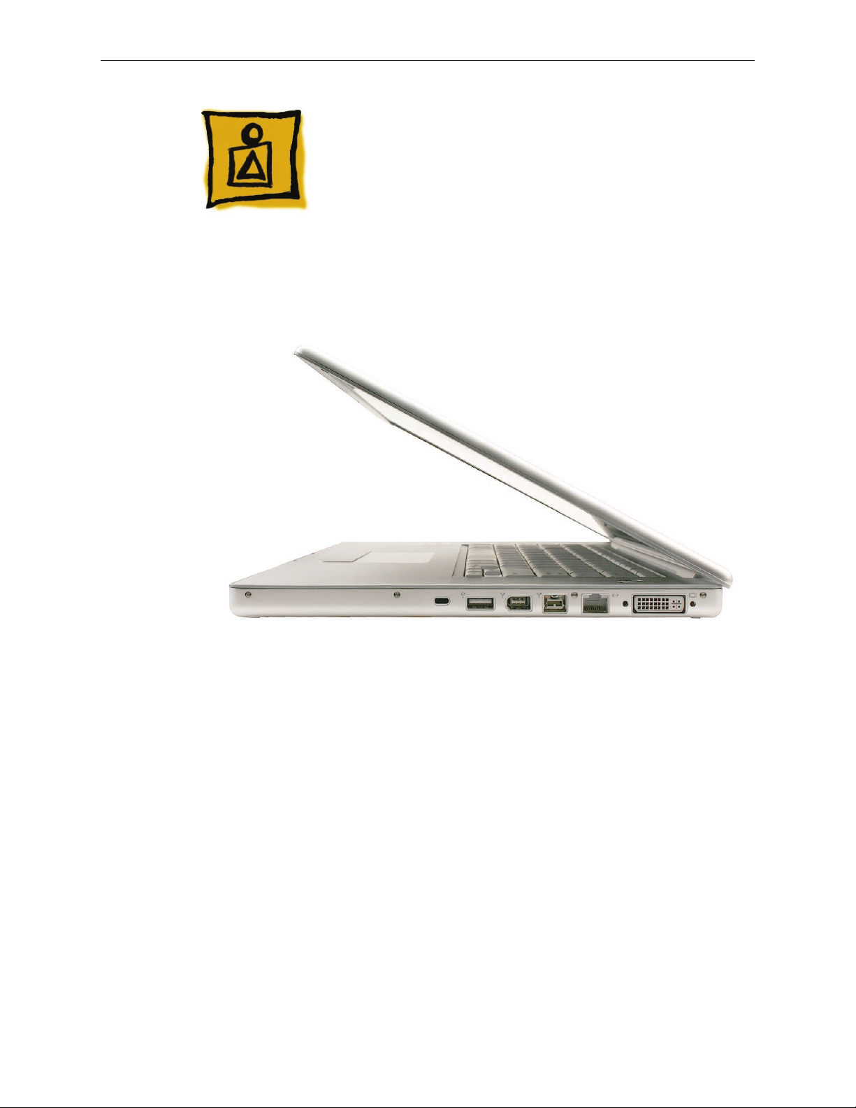
The MacBook Pro (15-inch Core 2 Duo) is the next generation of Intel-based MacBook Pro
professional notebooks. As the name implies, it is based upon the new Intel Core 2 Duo chip,
increasing processor speeds to 2.33GHz.
On the exterior, the MacBook Pro (15-inch Core 2 Duo) diers from its predecessor in two ways.
The LED for the iSight camera no longer depends an opening in the display bezel to be visible.
And more signicantly, the reintroduction of FireWire 800 adds a new port to the right side of the
bottom case, increasing the ports from four to ve.
A new MagSafe Airline Adapter is now available for both the MacBook Pro and the MacBook. Plug
the MagSafe Airline Adapter into the EmPower port nearest your airline seat. Some airlines may
have 20 mm in-seat ports that require the use of an additional adapter (included in the kit).
MacBook Pro (15-inch Core 2 Duo) Basics— General Information 6
Page 7
Main service and feature differences from previous models:
Intel Core 2 Duo microprocessor architecture: 2.33GHz and a 2.16GHz option
•
Up to 3GB DDR2 memory now supported
•
120GB 5400 RPM hard drive standard
•
100GB 7200 RPM hard drive optional
•
200GB 4200 RPM hard drive optional
•
FireWire 800 port
•
6x SuperDrive with dual-layer burning support
•
New trackpad-enabled zooming feature
•
New Parts and Procedures
Main Logic Board
The MacBook Pro (15-inch Core 2 Duo) not only hosts the Intel Core 2 Duo microprocessor chip,
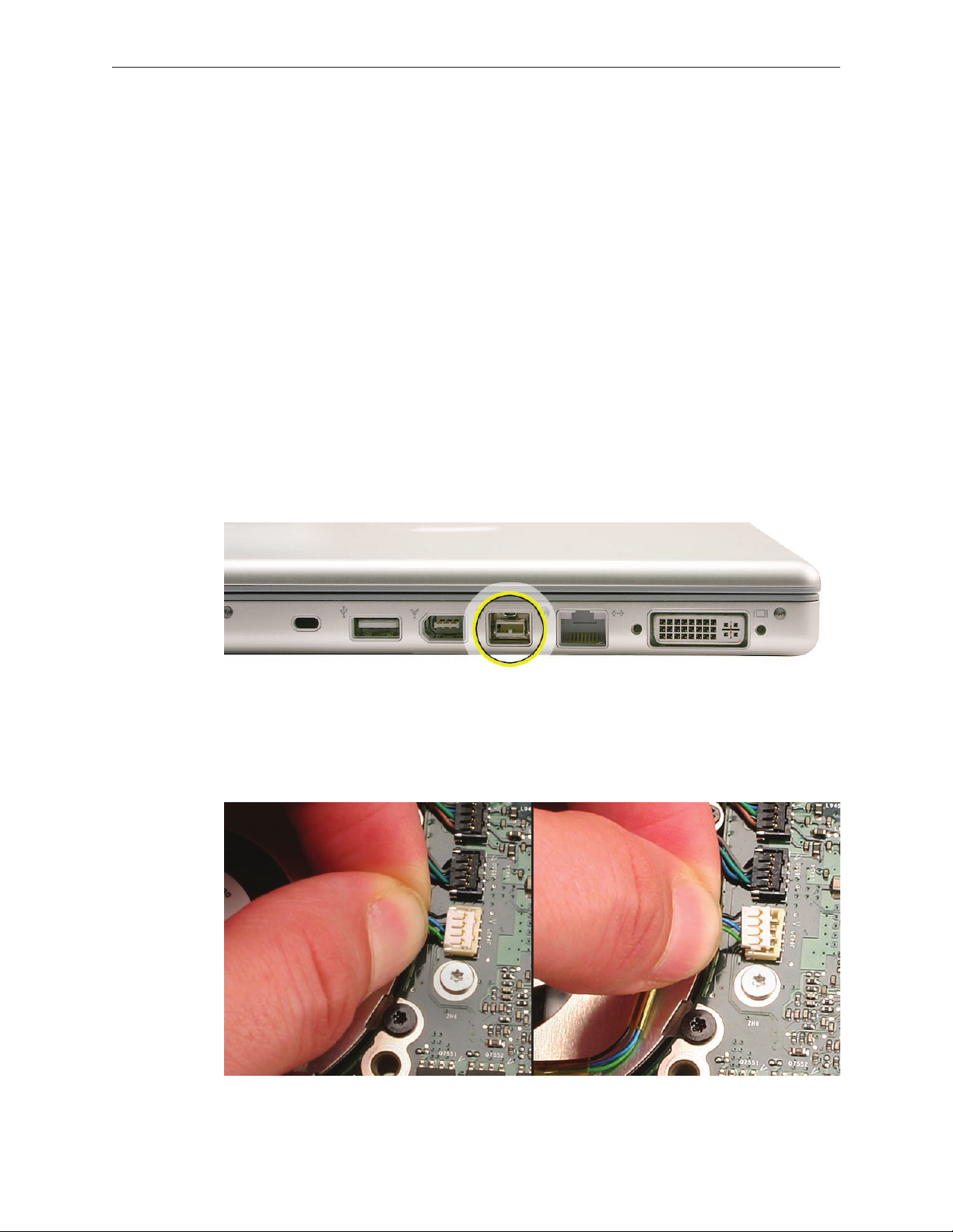
but it also reincorporates the popular 9-pin FireWire 800 port from the PowerBook series. Note
that the additional port makes this bottom case incompatible with previous the MacBook Pro.
Like the MacBook, the MacBook Pro (Core 2 Duo) now utilizes JST wire bundle connectors that
disengage by lifting up and pulling the connector out of its mating part on the logic board. Just
snap the connector back in. The fans, thermal sensors, and back battery all use this connector.
MacBook Pro (15-inch Core 2 Duo) Basics— General Information 7
Page 8
As with its predecessor, the composite and S-video connection is still available using the optional
Apple DVI to Video adapter. The microprocessor is soldered to the main logic board. It is not
upgradable.
Memory
The maximum supported amount of memory is 3 GB. While you will have a perfectly bootable
system with two (2) 2GB RAM modules installed—and even About This Mac will report 4GB of
installed memory—the system will only be able to address 3GB of that installed RAM.
AirPort Extreme
The AirPort Extreme card is a new design that utilizes a three-wire antenna solution. A colorcoded label will identify which wires go to which terminals on the card.
Bluetooth
The Bluetooth module and antenna have been moved from the bottom case near the hard drive
to a position underneath the top case.
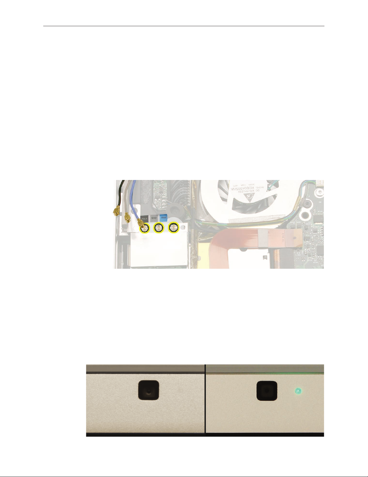
iSight Camera Status LED
The opening for the green status LED to the right of the camera no longer appears in the display
bezel. When the LED lights up, it is now visible through a clever pattern of micro perforations.
MacBook Pro (15-inch Core 2 Duo) Basics— General Information 8
Page 9
Keyboard
The keyboard backlighting has been improved. In addition, the programming of the caps lock
key was changed to x a developer keyboard mapping issue. Thus, this keyboard cannot be used
in previous MacBook Pro 15-inch systems. The caps lock key will not be recognized.
Right Speaker Assembly
The right speaker is now one single part. In the previous design, a speaker housing was mounted
below the main logic board and the right speaker driver was mounted through the main logic
board into the housing with its wire running over the top of the main logic board.
The new single piece design has the entire right speaker installed rst with the main logic board
placed over it. This design does require the entire main logic board to be removed to change the
right speaker. In addition, the right speaker wire now runs below the main logic board, under the
heat sink along back vent wall.
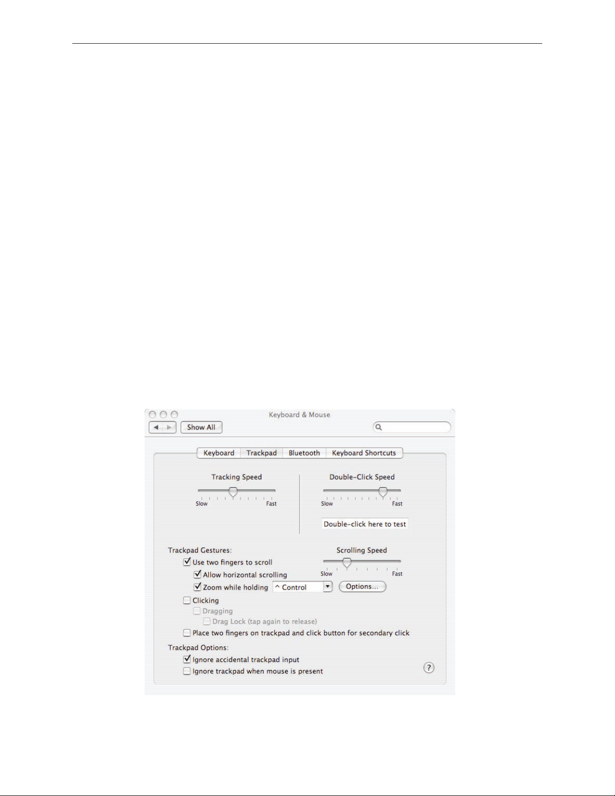
Trackpad
The trackpad now supports screen zooming, much like the keyboard-based Zoom feature in the
Universal Access System Preference pane. When holding down a user-selectable modier key (in
the Keyboard & Mouse System Preference pane), gesturing with a forward nger motion on the
trackpad will cause the image on the screen to zoom in. The reverse motion will zoom out.
MacBook Pro (15-inch Core 2 Duo) Basics— General Information 9
Page 10
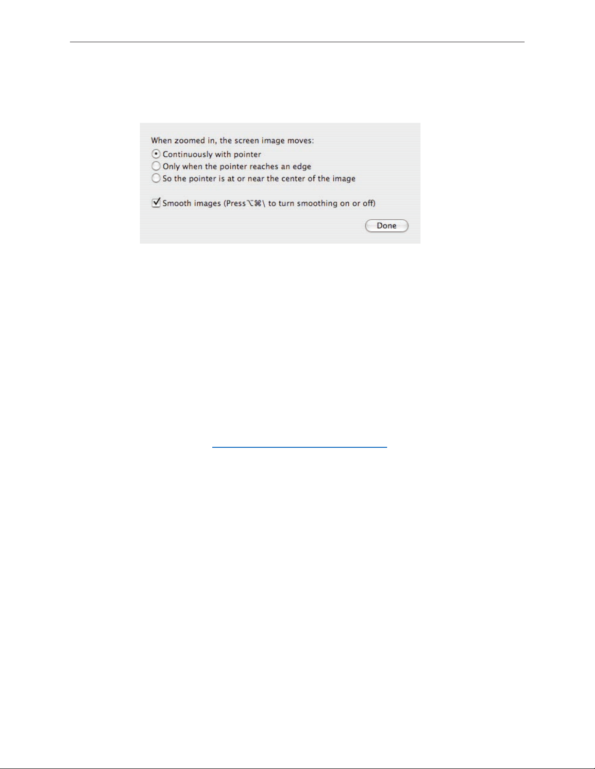
There are three users options that adjust how the customer can move within a zoomed screen
and how smooth the image will look.
Hard Drive
The hard drive comes with a metal disk attached to its top cover to dampen hard drive noise. This
disk is not removeable. The replacement drive will come with this dampener pre-installed.
Temperature Concerns
The customer may perceive this system to run hotter than previous models. However, the normal
operating temperature is well within national and international safety standards. Still, customers
may be concerned about the heat generated by their machine. To prevent an unnecessary repair,
you can compare a customer’s computer to a running model, if available, at your repair site.
For more information on temperature concerns and customer perception, refer to Knowledge
Base article 30612: Apple Notebooks: Operating Temperature.
Display Takeapart
With the MacBook Pro (15-inch Core 2 Duo), we have brought back the whole display clamshell
as a service part. However, unlike the 17-inch Core 2 Duo, we offers some parts which are
accessible by the removal of the display rear housing.
Specifically, a Service Provider can replace:
• Display hooks
• Inverter
• Display housing
• Sleep magnet
All other parts including the LVDS cable are serviced with the whole clamshell module.
MacBook Pro (15-inch Core 2 Duo) Basics— General Information 10
Page 11
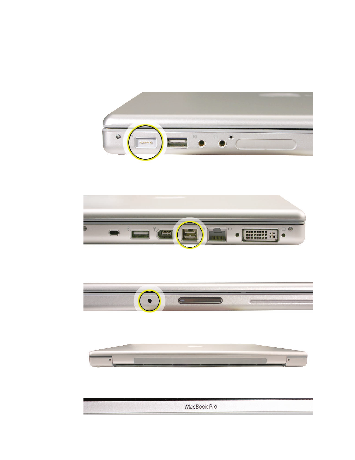
Identifying the MacBook Pro (15-inch Core 2 Duo)
Below are views of the MacBook Pro (15-inch Core 2 Duo), with identifying features.
Left side: MagSafe™ magnetic power connector.
Right side: New FireWire 800 port.
Front: Infrared sensor window.
Rear: Wider venting than previous MacBook Pro.
Display bezel: MacBook Pro.
MacBook Pro (15-inch Core 2 Duo) Basics— General Information 11
Page 12
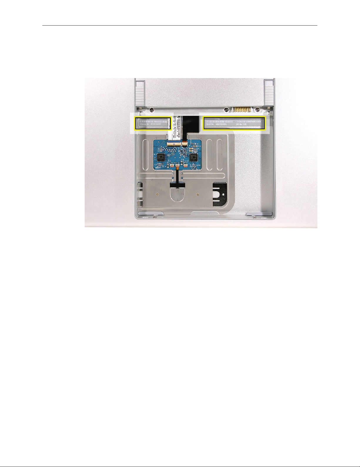
Serial Number and Ethernet ID
The Serial Number and Ethernet ID are located in the battery bay.
Tools
The takeapart procedure for the MacBook Pro (15-inch Core 2 Duo) requires the following tools:
Clean non-marring work surface
•
ESD wrist strap and mat
•
Multi-compartment screw tray (such as a plastic ice cube tray)
•
#0 Phillips screwdriver (magnetized)
•
#1 Phillips screwdriver (magnetized)
•
Torx T6 screwdriver (magnetized)
•
4 mm socket wrench
•
Black stick (nylon probe 922-5065) or other non-conductive nylon or plastic at-blade tool
•
Razor knife
•
Needle-point metal probe
•
Needlenose pliers
•
Tweezers
•
Kapton tape (922-1731) (0.5-inch x 12-yard roll)
•
Thermal grease (922-7144)
•
Gasket kit (076-1238)
•
Alcohol pads
•
Fine-point felt-tip permanent marker
•
Apple Pro keyboard and mouse (for troubleshooting)
•
MacBook Pro (15-inch Core 2 Duo) Basics— General Information 12
Page 13

Electrostatic Discharge (ESD)
Use a properly grounded ESD wrist strap and mat when working on the inside of the computer.
Service Manual Note
In this manual, graphics or photos are intended to help illustrate procedures or information only,
and may show dierent levels of disassembly, board colors, congurations, or computer models,
than your computer.
Kapton® Tape Note
Kapton tape is used to secure cables and connectors where necessary.
During disassembly, note any Kapton tape use and locations—reapply in the same manner. Do
not over apply or build up tape on top of old tape; space tolerances are tight and build up or
extraneous use of tape may cause pressure on other components.
Cable Routing Note
The MacBook Pro matches the same one-inch enclosure height established with the PowerBook
G4 17-inch series of systems. More so than ever, the placement of parts and wiring is critical.
During disassembly, note cable routing. Reassemble in the same manner. Verify that cables do
not route over components when they should route into lower positions or channels. Verify that
the cables are not strained or applying pressure onto other components.
Screw Measurement Note
All screw measurements given are the specied full length. Actual measured lengths may vary.
MacBook Pro (15-inch Core 2 Duo) Basics— General Information 13
Page 14

Service Source
Take Apart
MacBook Pro (15-inch Core 2 Duo)
© 2006 Apple Computer, Inc. All rights reserved.
Page 15
Foot
Tools
This procedure requires the following tools:
Foot kit
•
Tweezers or needlenose pliers
•
Soft cloth
•
Preliminary Step
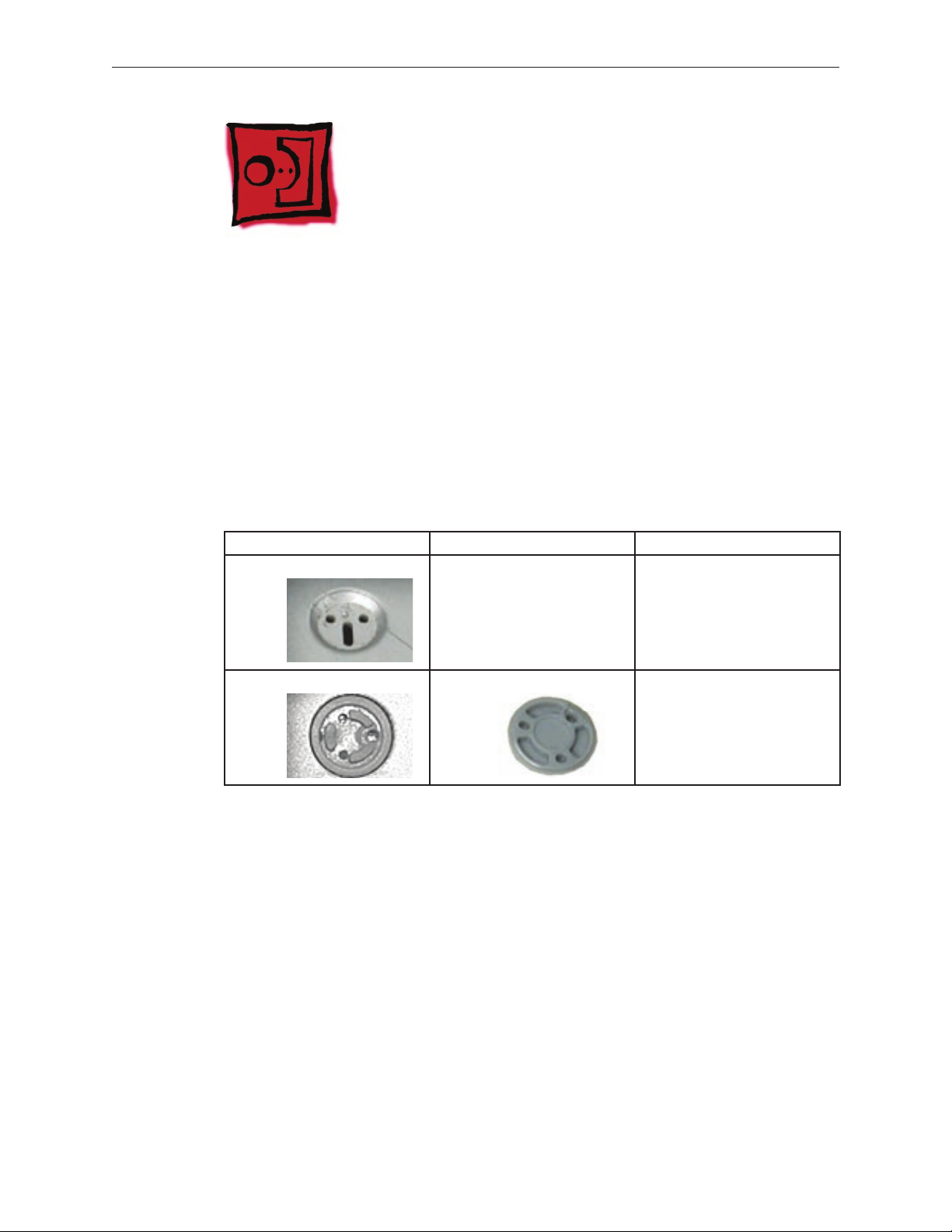
Before you begin, check the foot location that needs replacement and verify that the case plug is
attached. Also verify that the case plug, and the case foot in the kit, match the pictures below.
Plug Area on Bottom Case Matching Foot Action
Missing case plug Not available for replacement Replace the bottom case, or
send to Apple Repair Center.
Case plug Case foot Continue with the procedure,
matching the foot to the plug
on the bottom case.
MacBook Pro (15-inch Core 2 Duo) Take Apart — Foot 15
Page 16
Procedure
Warning: The glue used in this procedure can bond instantly to skin. Do not touch the glue.
In the event of contact, review the safety instructions at the end of this document. For
additional information, refer to the glue manufacturer:
Elmer’s Products, Inc.
Columbus, OH. 43215-3799
www.krazyglue.com
Place the computer upside down on a clean, lint-free cloth or other nonabrasive surface.
1.
Select a foot from the kit. Verify that the case plug and case foot match (refer to the images
2.
shown in the table). Do not use a foot that does not match.
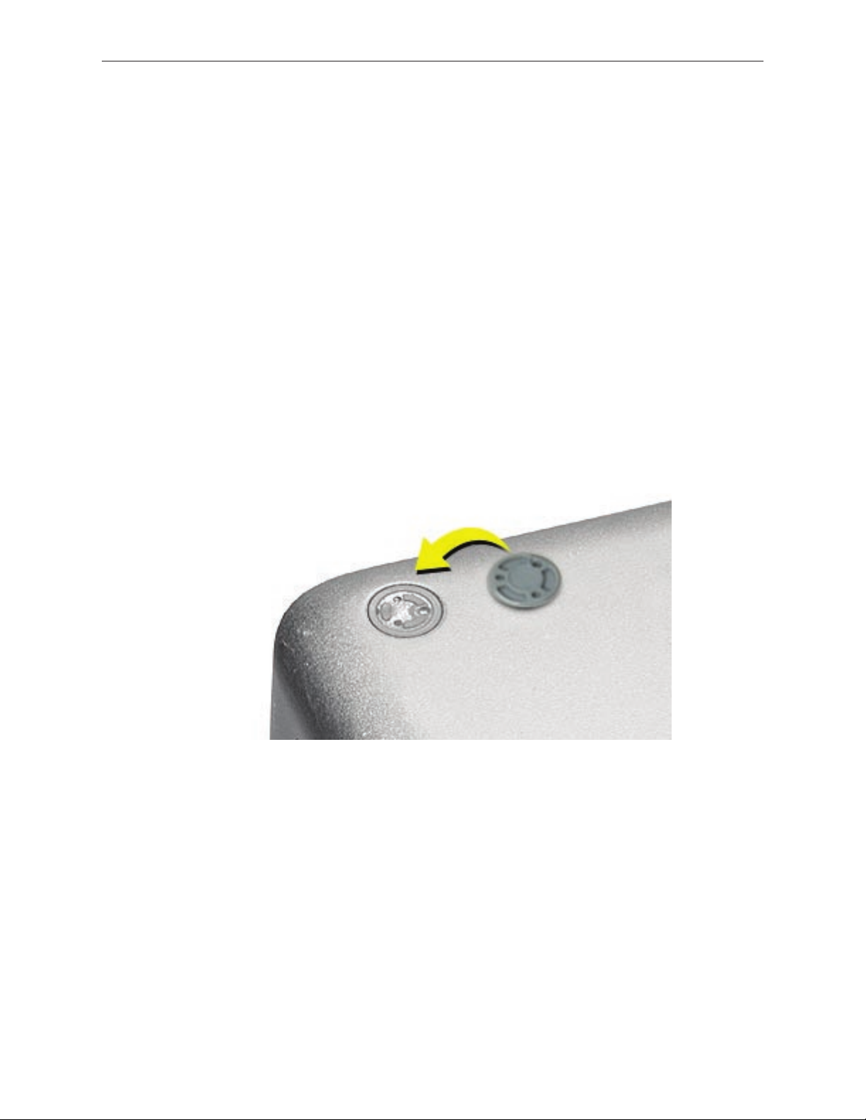
Make sure the plug area on the bottom case is clean. If any portion of the soft rubber foot
3.
remains, remove it so that only the hard plastic plug is visible.
Important: When positioning the foot, make sure the indents and bumps of the rubber foot
match up and t into the corresponding indents and bumps in the plug. This ensures a
balanced and level tting. (Note: The picture below may be a dierent foot than on the
computer, and is for illustration only.)
MacBook Pro (15-inch Core 2 Duo) Take Apart — Foot 16
Page 17
Warning: GLUE IS AN EYE AND SKIN IRRITANT. BONDS SKIN INSTANTLY. Do not touch the
4.
glue at any time. Before opening the glue, review the safety instructions at the end of
this document.
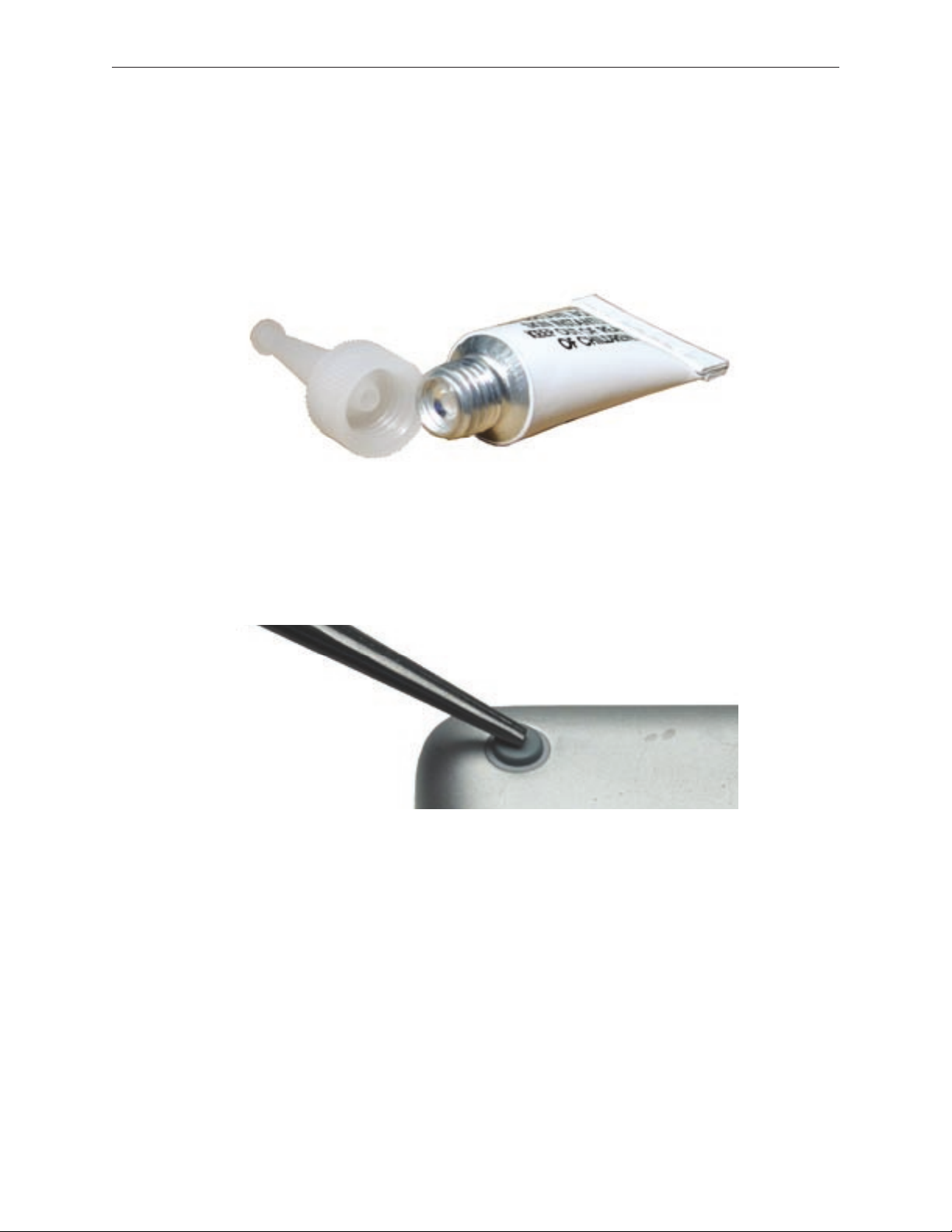
Important: The glue tube included in the kit is sealed until rst use. Do not break the seal
until you are ready to use the glue. To break the seal, hold the tube upright and away from
you. Place the hollow nozzle cap on the tube and tighten it all the way down. The tube is
then ready to dispense the glue through the nozzle cap.
Apply one drop of glue to the plug on the bottom case. Do not spread the glue.
5.
Using tweezers or needlenose pliers, carefully position the new foot so its textured surface
6.
ts into the inner ring of the plug.
Using the end of the tweezers or pliers—not your nger—lightly press and hold the foot in
7.
place for 30 seconds.
Before turning over the computer, allow the glue to set for at least 15 minutes.
8.
Discard the tube of glue.
9.
SAFETY INSTRUCTIONS: GLUE IS AN EYE AND SKIN IRRITANT. BONDS SKIN
INSTANTLY. Contains ethyl cyanoacrylate. Avoid contact with skin and eyes. If eye or mouth
contact occurs, hold eyelid or mouth open and rinse thoroughly but gently with water only for 15
minutes and GET MEDICAL ATTENTION. Liquid glue will sting eye temporarily. Solidied glue
may irritate eye like a grain of sand and should be treated by an eye doctor. If skin bonding occurs,
soak in acetone-based nail polish remover or warm soapy water and carefully peel or roll skin
apart (do not pull). Contact through clothing may cause skin burn. If spilled on clothing, ush with
cold water. Avoid prolonged breathing of vapors. Use with adequate ventilation. KEEP OUT OF
REACH OF CHILDREN.
MacBook Pro (15-inch Core 2 Duo) Take Apart — Foot 17
Page 18
Battery
Tools
This procedure requires the following tools:
Clean non-marring work surface
•
Preliminary Steps
Warning: Always shut down the computer before opening it to avoid damaging its internal
components or causing injury. After you shut down the computer, the internal components
can be very hot. Let the computer cool down before continuing.
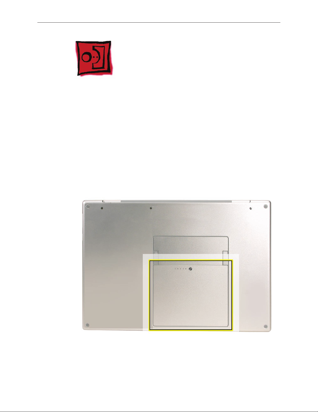
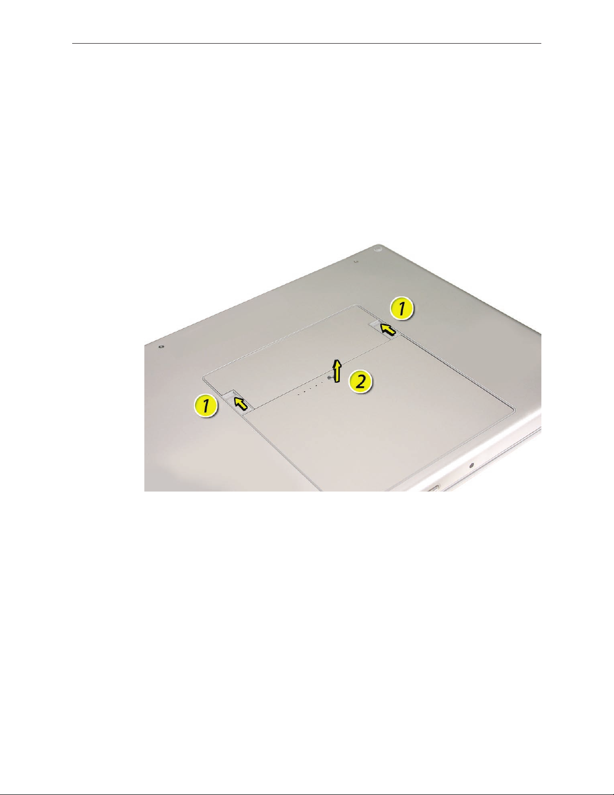
Part Location
MacBook Pro (15-inch Core 2 Duo) Take Apart — Battery 18
Page 19
Procedure
Warning: If the computer has been recently operating, allow it to cool down before
performing this procedure.
Shut down the computer.
1.
Disconnect the power cord and any other cables connected to the computer.
2.
Place the computer face down.
3.
Slide both battery latches away and lift the battery out of the battery bay.
4.
MacBook Pro (15-inch Core 2 Duo) Take Apart — Battery 19
Page 20
Memory
Tools
This procedure requires the following tools:
#0 Phillips screwdriver (magnetized)
•
Clean non-marring work surface
•
ESD wrist strap and mat
•
Preliminary Steps
Before you begin, remove the following:
Battery
•
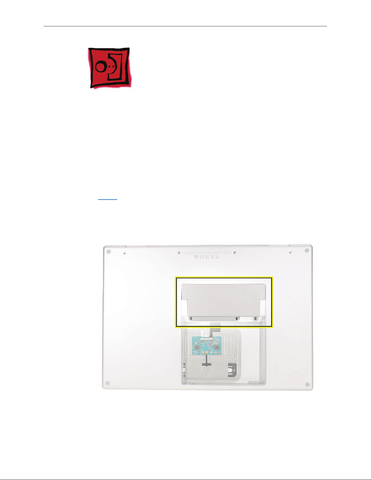
Part Location
MacBook Pro (15-inch Core 2 Duo) Take Apart — Memory 20
Page 21
Procedure
Warning: If the computer has been recently operating, allow it to cool down before
performing this procedure.
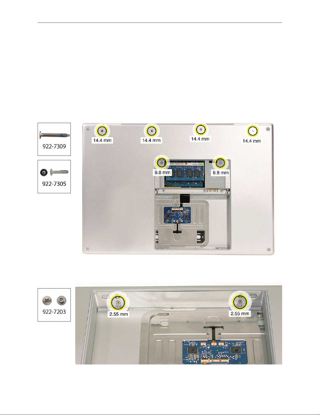
Place the computer face down.
1.
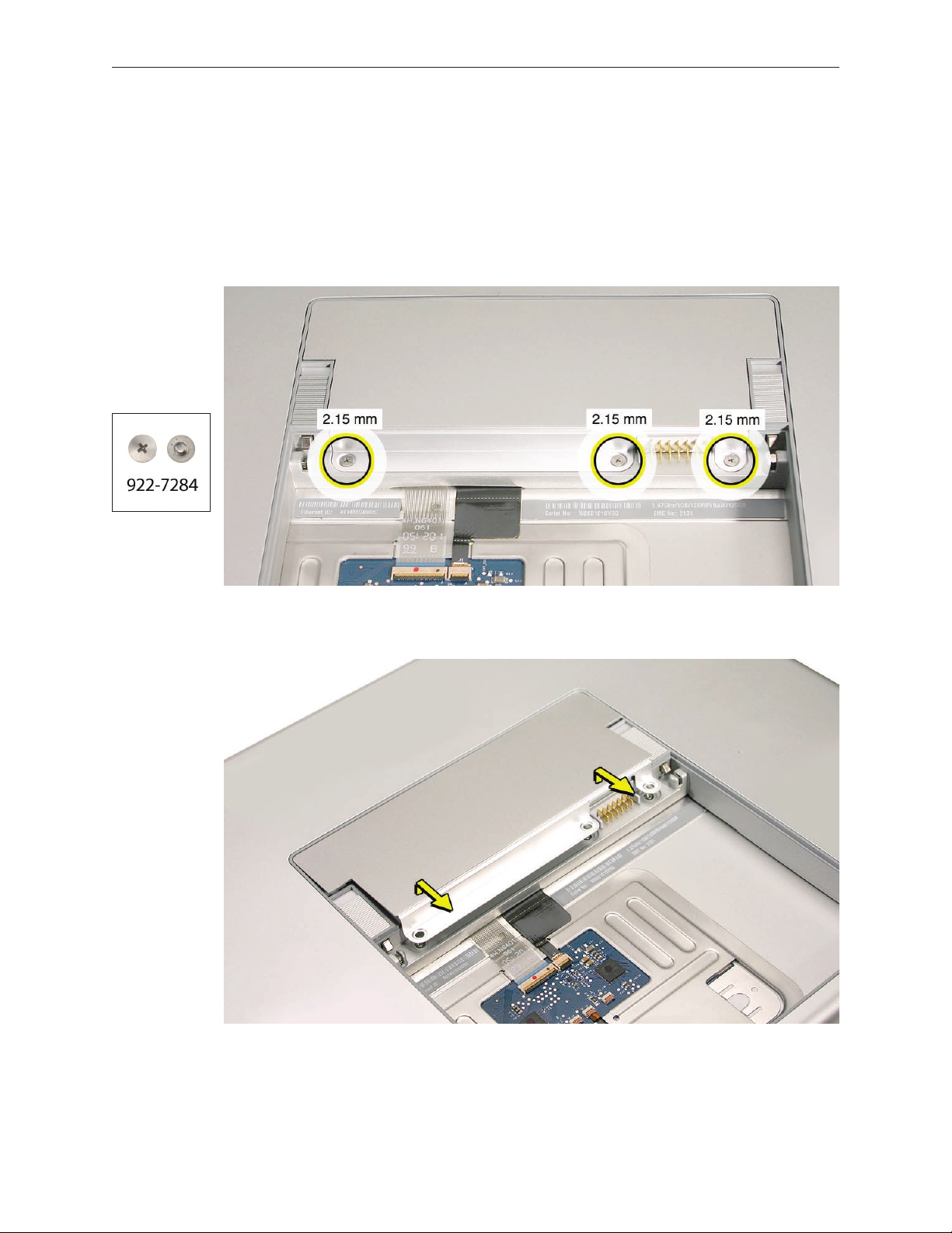
Remove the three screws from the memory door.
2.
Remove the door, as shown.
3.
Notes:
• If only one memory card is installed, the factory installs it in the bottom memory slot.
• Memory must be removed from the top slot before removing from the bottom slot.
MacBook Pro (15-inch Core 2 Duo) Take Apart — Memory 21
Page 22
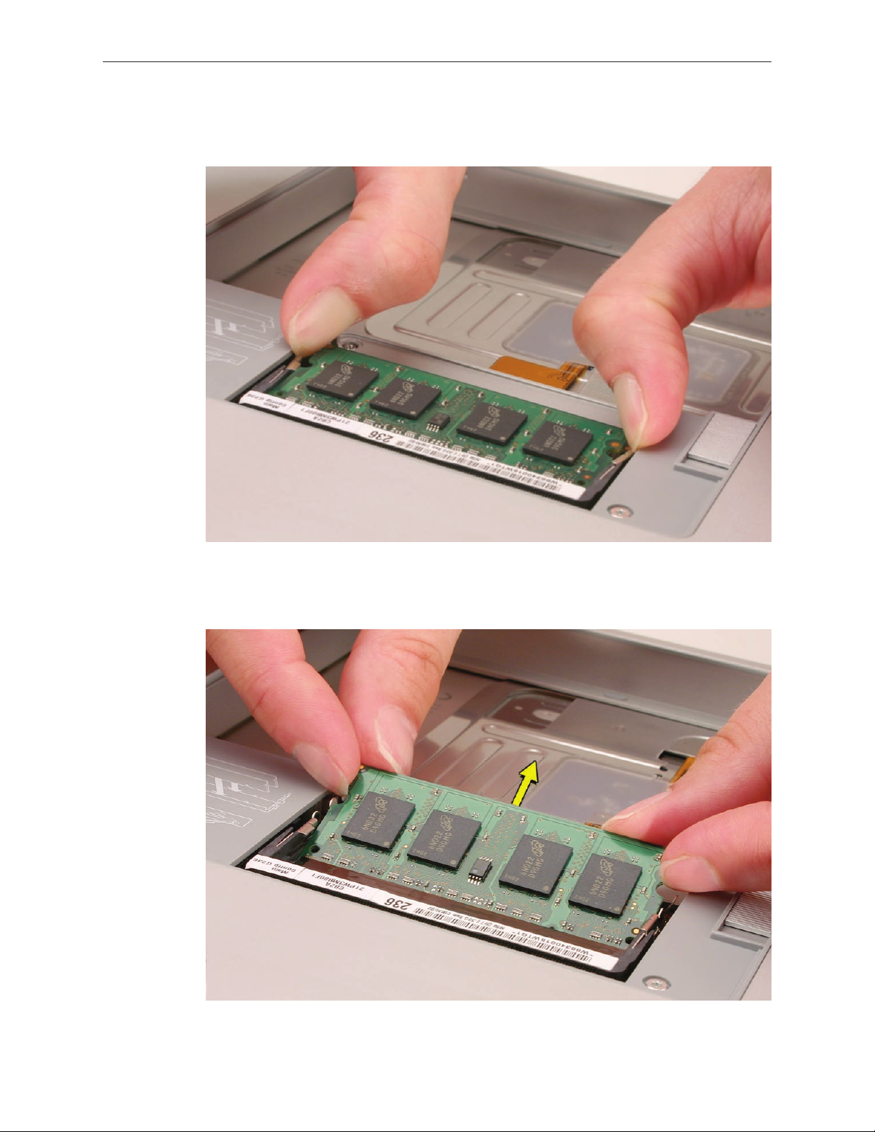
To remove memory cards, carefully spread the two locking tabs for the slot (top or bottom)
4.
away from the card on both sides and allow the card to pop up slightly.
Pull the card straight back and out of the memory slot. Handle the memory card by the
5.
edges only, taking care not to touch the gold contacts.
MacBook Pro (15-inch Core 2 Duo) Take Apart — Memory 22
Page 23
Replacement Procedure
Notes:
DDR memory cards do not t in this slot, only DDR2 (dierent notch location).
•
If installing two cards, install into the bottom slot rst.
•
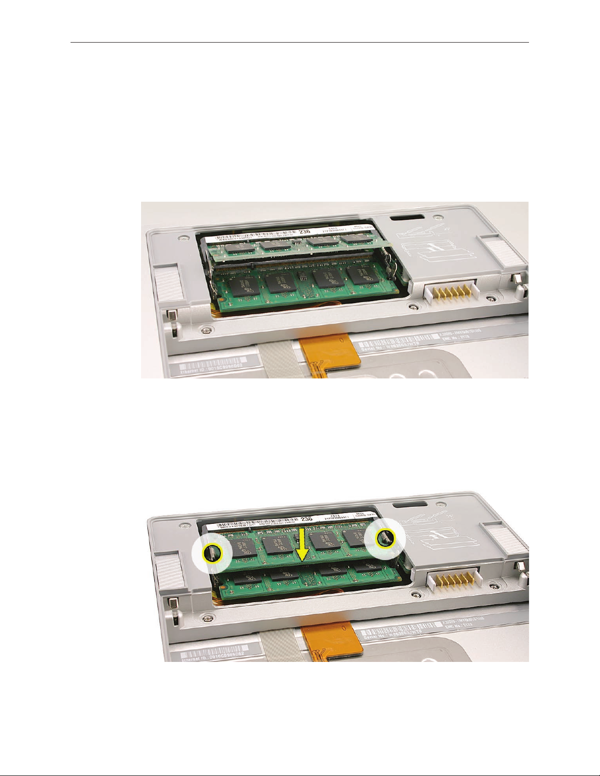
Align the notch in the memory card with the tooth in the slot before inserting.
•
To install a memory card into either the top or bottom slot, insert the card at a 25-degree
1.
angle behind the locking tabs.
Firmly push the card straight into the slot until it is fully and securely seated along its length.
2.
Note: If the back of the card drops down before it is fully seated, raise it up enough to push
it fully into the slot.
When the card is fully seated, push the card straight down until the tabs click onto both
3.
sides of the card, locking it into place.
MacBook Pro (15-inch Core 2 Duo) Take Apart — Memory 23
Page 24
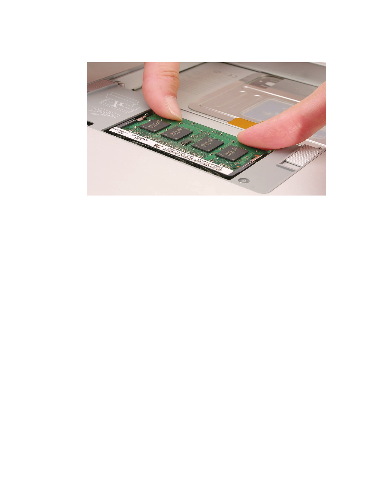
Verify that the card is fully seated by pushing rmly with your thumbs.
4.
Check that the cards are secured by the brackets on both sides.
5.
Install the memory door.
6.
Replace the battery.
7.
Use Apple System Proler to verify that the memory is recognized. (Choose the menu
8.
bar Apple logo () > About This Mac, click More Info..., select the System Prole tab,
open the Memory Overview.)
NOTE: As mentioned in the General Information section of this manual, the maximum supported
amount of memory in the MacBook Pro (15-inch Core 2 Duo) is 3 GB. While you will have a
perfectly bootable system with two (2) 2GB RAM modules installed—and even About This
Mac will report 4GB of installed memory—the system will only be able to address 3GB of that
installed RAM.
MacBook Pro (15-inch Core 2 Duo) Take Apart — Memory 24
Page 25
Top Case
Tools
This procedure requires the following tools:
#0 Phillips screwdriver (magnetized)
•
Torx T6 screwdriver (magnetized)
•
Black stick (nylon probe 922-5065) or other non-conductive nylon or plastic at-blade tool
•
Multi-compartment screw tray (such as a plastic ice cube tray)
•
Preliminary Steps
Before you begin, remove the following:
Battery
•
Memory Door
•
Part Location
MacBook Pro (15-inch Core 2 Duo) Take Apart — Top Case 25
Page 26
Procedure
Notes:
If replacing the top case, once the top case is removed, use a razor knife to carefully lift and
•
transfer the Serial Number and Ethernet ID labels to the replacement top case.
This procedure removes the top case and keyboard assembly. The keyboard is removable
•
only after removing the top case.
Place the computer upside down on a soft, non-marring surface.
1.
Remove the four Phillips and two Torx T6 screws shown.
2.
Rotate the computer and remove the two Phillips screws along the front of the battery bay.
3.
MacBook Pro (15-inch Core 2 Duo) Take Apart — Top Case 26
Page 27
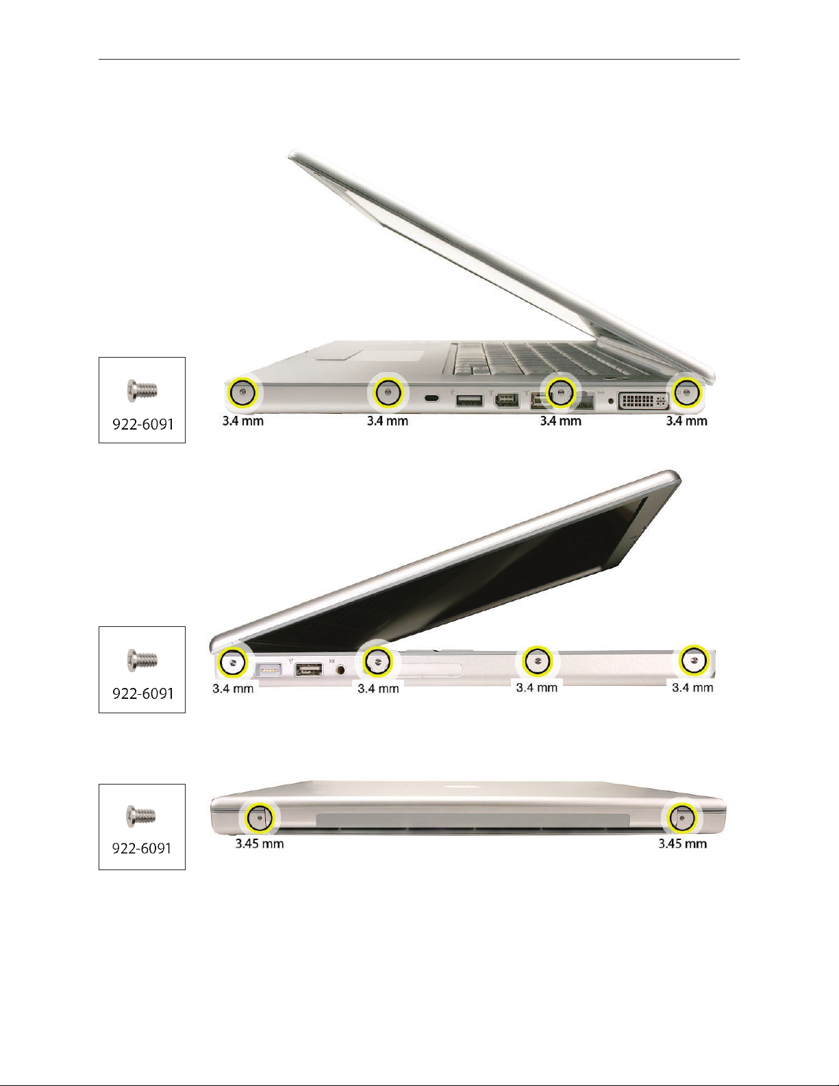
Remove the four Phillips screws from each side.
4.
Remove the two Phillips screws from the back edge.
5.
.
MacBook Pro (15-inch Core 2 Duo) Take Apart — Top Case 27
Page 28
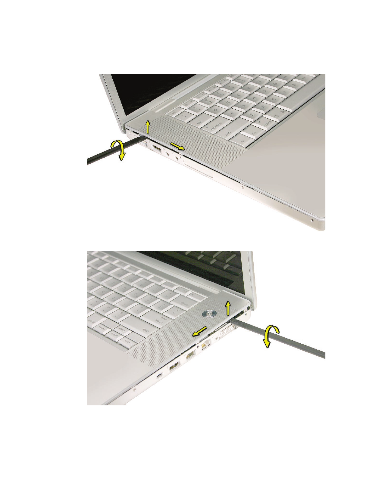
Face the computer forward and open the display slightly past 90-degrees.
6.
Use a black stick to loosen the top case along the rear of the left and right sides.
7.
MacBook Pro (15-inch Core 2 Duo) Take Apart — Top Case 28
Page 29
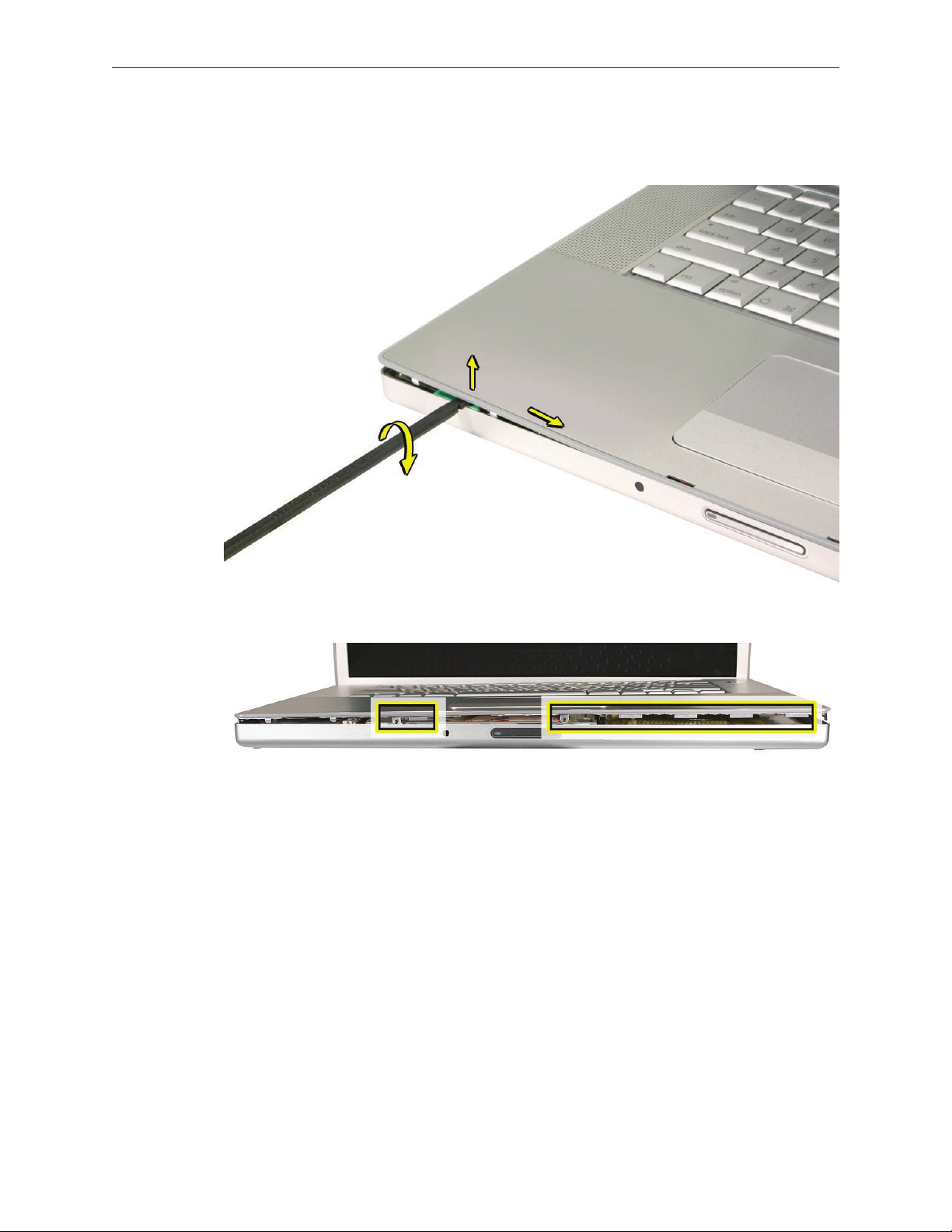
Along the front, start at the left and slowly encourage the snaps and screw tabs (shown in
8.
graphic below) to release as you move right. A snapping noise as the snaps release is normal.
Important: Do not lift the case once it is free—it is still connected to the bottom case by the
keyboard ex cable.
MacBook Pro (15-inch Core 2 Duo) Take Apart — Top Case 29
Page 30
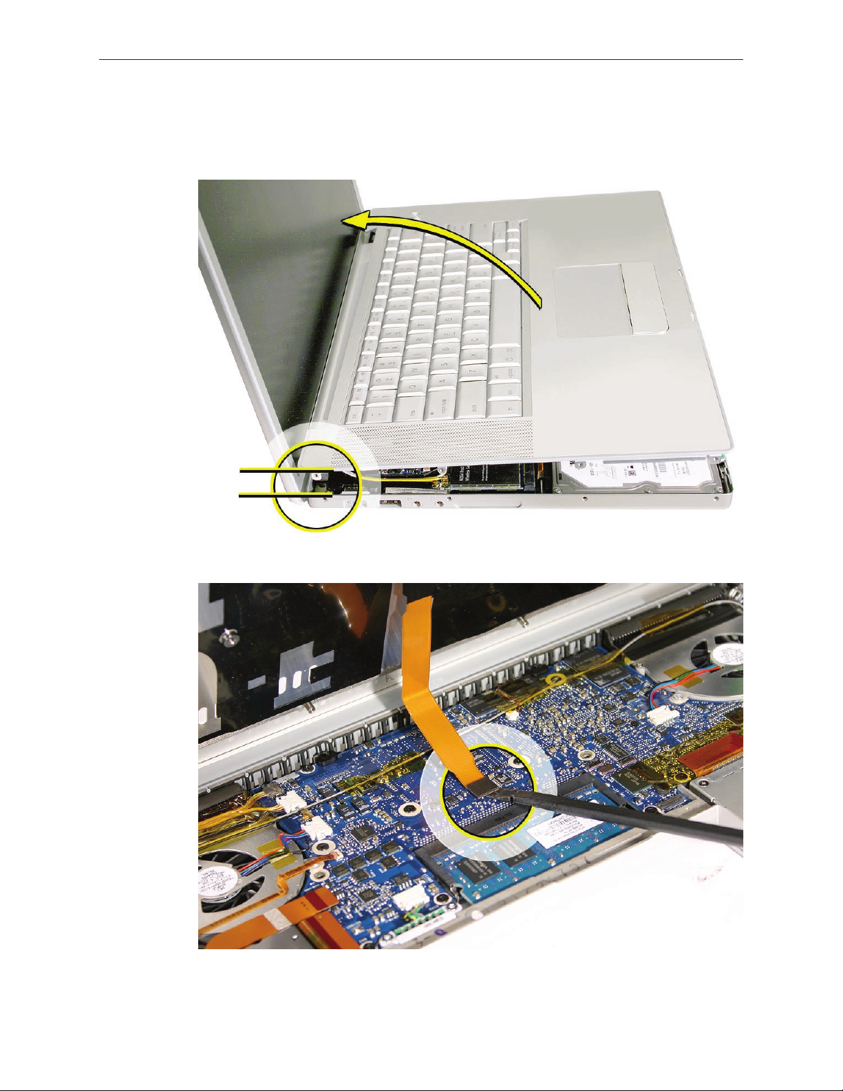
Important: To avoid bending screw tabs along the back edge of the top case, lift the top
9.
case slightly so that it does NOT touch the bottom case, then rotate the front of the case up
and back until you can disconnect the keyboard ex cable from the logic board.
MacBook Pro (15-inch Core 2 Duo) Take Apart — Top Case 30
Page 31

Replacement Procedure
Note: If replacing the top case, remove the keyboard and transfer to the replacement top case.
Visually check to verify that all cables are connected and routed correctly with nothing raised
1.
up or incorrectly over a component.
Check perimeter wiring and cables around clutches to verify that they will not be caught or
2.
pinched by the top case during replacement.
On the computer, verify that all cables are secure and lay at.
3.
On the top case, check cable connections and routing.
4.
MacBook Pro (15-inch Core 2 Duo) Take Apart — Top Case 31
Page 32

Check that the perimeter screw tabs and ribs are not bent.
5.
Note: The metal can quickly fatigue and break o. Be extremely careful to gently straighten
tabs, if needed.
Verify that the plastic spacer is on the front screw tab, shown.
6.
MacBook Pro (15-inch Core 2 Duo) Take Apart — Top Case 32
Page 33

Verify that the screw tabs in back are straight and guide them inside the bottom case. Work
7.
your way around guiding the screw tabs into the bottom case along both sides.
If the back screw tabs are bent out, straighten by pressing the edge of the case on a hard at
8.
surface and rolling to vertical.
MacBook Pro (15-inch Core 2 Duo) Take Apart — Top Case 33
Page 34

Any screw tabs that are not straight will not t or accept screws correctly.
9.
Use your nger and a black stick to carefully straighten bent screw tabs.
10.
MacBook Pro (15-inch Core 2 Duo) Take Apart — Top Case 34
Page 35

Connect the ex cable from the top case to the logic board.
11.
Lift the top case o the bottom case slightly and rotate it down (verify that the keyboard
12.
cable stays connected and is folding properly) and align the corners.
Carefully pull or push tabs slightly, if needed. Note: Guarded, controlled pushing with your
13.
thumb may be helpful to nesse the tabs into place.
The two front screw tabs may need to be guided with a black stick through the battery bay.
14.
Squeeze at the snap locations (shown below) along the front edge of the top case to verify
15.
that the they are seated. The top case should lay at along all sides and top, if not, make sure
that cables and components are not interfering.
Reinstall the left and right side screws.
16.
Important: Do not insert screws into the DVI port screw holes. If they get stuck, it may
require removing the logic board to dislodge.
MacBook Pro (15-inch Core 2 Duo) Take Apart — Top Case 35
Page 36

Install the bottom Phillips screws and the two Torx T6 screws near the memory.
17.
Install the two Phillips screws along the back.
18.
.
MacBook Pro (15-inch Core 2 Duo) Take Apart — Top Case 36
Page 37

Install the two Phillips screws in the battery bay.
19.
Important: For the screw shown, push in the display latch button while installing the screw.
Install the memory door and replace the battery.
20.
Testing the computer should include:
21.
Powering on, checking the keyboard and trackpad function.
•
Operate the computer in a darkened room to check for keyboard backlight function.
•
Verify Bluetooth operation by checking that the it appears in either the Apple Menu bar
•
or in the Apple System Proler USB section.
MacBook Pro (15-inch Core 2 Duo) Take Apart — Top Case 37
Page 38

Keyboard
Tools
This procedure requires the following tools:
#0 Phillips screwdriver (magnetized)
•
Black stick (nylon probe 922-5065) or other non-conductive nylon or plastic at-blade tool
•
Preliminary Steps
Before you begin, remove the following:
Battery
•
Top Case
•
Part Location
MacBook Pro (15-inch Core 2 Duo) Take Apart — Keyboard 38
Page 39

Procedure
Important Notes:
The MacBook Pro (Core 2 Duo) keyboard is not interchangeable with previous models, even
•
the original MacBook Pro. Verify that the correct replacement keyboard is ordered, and/or
top case if replacing.
The keyboard comes as a multi-layered assembly, and includes backlighting. Do not
•
disassemble the keyboard assembly. Dust, ngerprints, or misalignment, can cause improper
function and damage.
On a clean at surface, turn the top case upside down.
1.
Locate the protective cover over ex cable connectors.
2.
MacBook Pro (15-inch Core 2 Duo) Take Apart — Keyboard 39
Page 40

Carefully slide a black stick around the perimeter of the cover to release the adhesive.
3.
Lift o the cover and set aside for reassembly. Important: Keep the cover and any residual
4.
adhesive on the top case clean.
Rotate the top case and locate the two keyboard ex connectors shown below. Remove any
5.
Kapton tape, then very carefully lift the latches of the connectors to release the cables.
Important: The connectors are delicate. If damaged, the top case must be replaced.
MacBook Pro (15-inch Core 2 Duo) Take Apart — Keyboard 40
Page 41

Note the positioning, then carefully peel o the insulator lm covering the back of the
6.
keyboard well. Reserve the lm and keep it clean for reinstallation.
Important: Use care at notches and narrow parts to avoid ripping the lm.
Important: Do not remove the rubber pad if not replacing the top case. If replacing the top
case, transfer it to the same location.
MacBook Pro (15-inch Core 2 Duo) Take Apart — Keyboard 41
Page 42

Use needlenose pliers to straighten the four bend-tabs located along the bottom edge, as
7.
shown. These tabs lock down and stien the top edge of the keyboard. Important: The
bend-tabs are delicate. Bend them carefully to avoid damage. Avoid over-bending.
Remove the ten Phillips #00 keyboard screws.
8.
MacBook Pro (15-inch Core 2 Duo) Take Apart — Keyboard 42
Page 43

Note the six insert-tabs along the middle edge, and two on each side. The following
9.
procedures release these tabs so that the keyboard can be removed.
To prevent the keyboard from falling out, support it with your hand, and raise the top case
10.
up vertically. Note: The keyboard does not have adhesive under it, as in previous models.
MacBook Pro (15-inch Core 2 Duo) Take Apart — Keyboard 43
Page 44

If needed, push through one of the top center keyboard screw holes, with the point of a
11.
black stick, to bow out the keyboard slightly.
Important: Ensure that the hole used is a screw hole, or damage to other sensitive
components may result. A black stick is used to avoid damaging the screw boss threads—do
not use a metal tool.
Important: During this procedure, do not allow the tabs or metal edge of the keyboard to
12.
scrape along the cosmetic surface of the top case, or damage can result.
MacBook Pro (15-inch Core 2 Duo) Take Apart — Keyboard 44
Page 45

Use your nger to hold the bowed out keyboard. Continue to bow it out only enough for the
13.
tabs on one side of the keyboard to release cleanly. Repeat for the other side.
Important: Do not bow the keyboard too much, or it may become permanently bent.
MacBook Pro (15-inch Core 2 Duo) Take Apart — Keyboard 45
Page 46

Lift the keyboard up to release the tabs along the bottom edge and carefully thread out the
14.
ex cables.
MacBook Pro (15-inch Core 2 Duo) Take Apart — Keyboard 46
Page 47

Replacement Procedure
When replacing the keyboard, here are some key points to ensure:
Prevention of scratches to the cosmetics of the top case
•
All tabs are properly seated
•
Keyboard lays at
•
Cables are not caught
•
Bend-tabs are not damaged
•
Screw holes align
•
Cable connectors are not damaged and cables are secure
•
Kapton tape is applied as before
•
Insulator lm is correctly installed
•
Before replacing or installing a replacement keyboard, verify that the four bend-tabs along
1.
the bottom edge of the keyboard are straight and parallel with the bottom edge (two are
shown close-up, below).
Important: Do not bend any other bend-tabs on the keyboard other than the four along the
bottom. Other tabs hold the keyboard assembly together.
MacBook Pro (15-inch Core 2 Duo) Take Apart — Keyboard 47
Page 48

Guide the keyboard’s ex cables through the slot in the top case, as shown. Make sure that
2.
they do not catch or bend behind the keyboard.
Verify that the small cable routes through the slot, as shown.
3.
MacBook Pro (15-inch Core 2 Duo) Take Apart — Keyboard 48
Page 49

Lower the keyboard and seat all six tabs along the bottom, so that the keyboard sits at and
4.
straight.
Important: During the next steps, do not allow the tabs or metal edge of the keyboard to
scrape along the cosmetic surface of the top case, or damage can result.
While ensuring that the keyboard bottom stays straight and secure, hold the top of the
5.
keyboard in the middle, then with your other hand, bow in one side of the keyboard to
engage the two tabs at the top into the top case.
Important: Do not bow the keyboard too much, or it may become permanently bent.
MacBook Pro (15-inch Core 2 Duo) Take Apart — Keyboard 49
Page 50

Use the heel of your hand to hold in place the edge of the keyboard that was just inserted
6.
while holding the top of the keyboard with a nger on that hand, then use your other hand
to help bow in the remaining side of the keyboard until it can be engaged.
MacBook Pro (15-inch Core 2 Duo) Take Apart — Keyboard 50
Page 51

While supporting the keyboard in the top case, verify that the keyboard lays at and that all
7.
the tabs have seated properly.
Note: The keyboard will not sit at if any of the tabs have not seated properly. If the side tabs
are not seating or are binding, check the bottom edge of the keyboard to verify that all the
tabs are seated and the bottom of the keyboard is straight.
Verify that the bend-tabs are not caught.
8.
Lay the top case at, and upside down.
9.
Pull on the ex cables to verify that they are not bent or caught under the keyboard, and
10.
that they extend to their connectors.
Verify that the screw holes align with the screw bosses and install all ten keyboard screws,
11.
starting from the middle and work out.
Bend the four bend-tabs over the metal of the bottom case to secure the bottom edge of
12.
the keyboard.
Important: The bend-tabs are delicate. Bend them carefully to avoid damage and no more
than 90 degrees, or to, or within, any etch marks, if present. Avoid over-bending.
MacBook Pro (15-inch Core 2 Duo) Take Apart — Keyboard 51
Page 52

13.
Insert the two ex cables into their connectors and secure. Verify that the cables are fully
inserted and secured straight. Kapton tape will be applied to the small connector later.
Reinstall the protective cover over the area shown. Line up the edges carefully with the
14.
residual adhesive, then carefully burnish down the edges to secure. (top case shown rotated)
MacBook Pro (15-inch Core 2 Duo) Take Apart — Keyboard 52
Page 53

Replace the insulator lm in the same locations as they were removed. Ensure the holes in
15.
the lm match up correctly with the screw bosses. Avoid wrinkles and bulges. If installing a
replacement top case, use the new lm if supplied.
Important: The lm must be installed in the same location to protect against contact and
electrical shorting in certain areas and to allow contact with the EMI spring on the logic
board.
Install Kapton tape to secure the small ex cable connector.
16.
Verify that the rubber pads (mentioned earlier) are installed in the correct locations.
17.
If the lm extends over the edge of the keyboard well, run your nger along the edges to
18.
secure it to the top case.
Note: Picture for illustration only. The insulator lm may be dierent.
Reassemble the computer.
19.
Testing the computer should include powering on, checking the keyboard and trackpad
20.
function. Operate the computer in a darkened room to check for keyboard backlight
function, and light leakage around the perimeter of the keyboard, speaker grill openings and
side ports.
MacBook Pro (15-inch Core 2 Duo) Take Apart — Keyboard 53
Page 54

AirPort Extreme Card
Tools
This procedure requires the following tools:
Torx T6 screwdriver (magnetized)
•
Black stick (nylon probe 922-5065) or other non-conductive nylon or plastic at-blade tool
•
Kapton tape (922-1731) (0.5-inch x 12-yard roll)
•
Preliminary Steps
Before you begin, remove the following:
Battery
•
Top Case
•
Part Location
MacBook Pro (15-inch Core 2 Duo) Take Apart — AirPort Extreme Card 54
Page 55

Procedure
Remove the three antenna connectors. Lift straight up.
1.
Remove the Torx T6 screw and bracket. The card should rise up slightly.
2.
Pull the card straight out.
3.
MacBook Pro (15-inch Core 2 Duo) Take Apart — AirPort Extreme Card 55
Page 56

When installing the replacement card, verify that the cables alongside rest in the channel
4.
and do not get caught underneath.
Verify that the antenna cables route at in the channel on the left speaker. Secure with
5.
Kapton tape, if necessary.
Connect each antenna cable to its respective terminal. Note that the color of each antenna
6.
cable corresponds with a matching color key located above the terminals.
Verify that the ambient light sensor ex cable is connected properly.
7.
Reassemble the computer.
8.
Testing should include AirPort function.
9.
MacBook Pro (15-inch Core 2 Duo) Take Apart — AirPort Extreme Card 56
Page 57

Bluetooth Card
Tools
This procedure requires the following tools:
#0 Phillips screwdriver (magnetized)
•
Black stick (nylon probe 922-5065) or other non-conductive nylon or plastic at-blade tool
•
Kapton tape (922-1731) (0.5-inch x 12-yard roll)
•
Preliminary Steps
Before you begin, remove the following:
Battery
•
Top Case
•
Part Location
MacBook Pro (15-inch Core 2 Duo) Take Apart — Bluetooth Card 57
Page 58

Procedure
Disconnect the Bluetooth antenna connector from the Bluetooth card, pulling straight up.
1.
Remove one Phillips screw from the lower right corner of the Bluetooth card.
2.
Remove the plastic protective cover by sliding it gently o the card, taking care to preserve
3.
its integrity for reuse. Set the cover aside to use with the replacement Bluetooth card.
Holding the Bluetooth card by its edges, use a black stick to disconnect the cable connector
4.
from the card as shown below.
Replacement Note: Before attaching the new Bluetooth card to the top case, install the plastic
cover retained from the old card over the replacement and secure with Kapton tape if necessary.
MacBook Pro (15-inch Core 2 Duo) Take Apart — Bluetooth Card 58
Page 59

Replacing the Bluetooth cable
To remove or replace the Bluetooth cable, gently pry up adhesive using a black stick.
1.
Disconnect the other end of the cable as shown.
2.
MacBook Pro (15-inch Core 2 Duo) Take Apart — Bluetooth Card 59
Page 60

Bluetooth Antenna
Tools
This procedure requires the following tools:
#0 Phillips screwdriver (magnetized)
•
Black stick (nylon probe 922-5065) or other non-conductive nylon or plastic at-blade tool
•
Razor knife
•
Kapton tape (922-1731) (0.5-inch x 12-yard roll)
•
Preliminary Steps
Before you begin, remove the following:
Battery
•
Top Case
•
Part Location
MacBook Pro (15-inch Core 2 Duo) Take Apart — Bluetooth Antenna 60
Page 61

Procedure
1. Disconnect the Bluetooth antenna connector from the Bluetooth card, pulling straight up.
2. Remove two Phillips screws from black plastic antenna shield.
3. Pry shield up from top case using a black stick, taking care to preserve adhesive underneath
if possible.
MacBook Pro (15-inch Core 2 Duo) Take Apart — Bluetooth Antenna 61
Page 62

3. Use a black stick to remove the antenna, prying it up to release the adhesive.
Replacement Note: If you remove the Bluetooth board during antenna replacement, reapply its
protective cover and secure with Kapton tape if necessary before reinstalling on top case.
MacBook Pro (15-inch Core 2 Duo) Take Apart — Bluetooth Antenna 62
Page 63

Infrared Board
Tools
This procedure requires the following tools:
Torx T6 screwdriver (magnetized)
•
Black stick (nylon probe 922-5065) or other non-conductive nylon or plastic at-blade tool
•
Preliminary Steps
Before you begin, remove the following:
Battery
•
Top Case
•
Part Location
MacBook Pro (15-inch Core 2 Duo) Take Apart — Infrared Board 63
Page 64

Procedure
Disconnect the cable.
1.
Remove the Torx T6 screw and bracket.
2.
Using a black stick, lift out the infrared board. Lifting from both ends may be helpful.
1.
Important: Lift on the board only. Do NOT lift the infrared lens or sensor piece. It is secured
to the main board with two wires and will bend out of alignment.
MacBook Pro (15-inch Core 2 Duo) Take Apart — Infrared Board 64
Page 65

Note the cable routing and remove.
2.
Replacement Procedure
Route the cable.
1.
To install, insert the board all the way into the channel, then push it forward until it stops
2.
and the infrared lens aligns with the window.
Important: Push on the board only. Do NOT push on the infrared lens or sensor piece. It is
secured to the main board with two wires and will bend out of alignment.
Connect the cable connector.
3.
MacBook Pro (15-inch Core 2 Duo) Take Apart — Infrared Board 65
Page 66

Hard Drive
Tools
This procedure requires the following tools:
#0 Phillips screwdriver (magnetized)
•
Torx T6 screwdriver (magnetized)
•
Black stick (nylon probe 922-5065) or other non-conductive nylon or plastic at-blade tool
•
Kapton tape (922-1731) (0.5-inch x 12-yard roll)
•
Preliminary Steps
Before you begin, remove the following:
Battery
•
Top Case
•
Part Location
MacBook Pro (15-inch Core 2 Duo) Take Apart — Hard Drive 66
Page 67

Procedure
Carefully pry up the ex cable from the hard drive.
1.
Lift up cabling to gain some clearance.
2.
MacBook Pro (15-inch Core 2 Duo) Take Apart — Hard Drive 67
Page 68

Remove the two Phillips #0 screws from the drive bracket.
3.
Remove the hard drive bracket.
4.
MacBook Pro (15-inch Core 2 Duo) Take Apart — Hard Drive 68
Page 69

Using a black stick, tilt the hard drive up slightly on the right side; then work the hard drive
5.
out of its grommet wells on the left side and lift up just enough to access the ex connector.
If there is Kapton tape securing the ex connector, remove it very carefully to ensure that
6.
you don’t damage the label. A damaged label voids the warranty of the hard drive.
MacBook Pro (15-inch Core 2 Duo) Take Apart — Hard Drive 69
Page 70

The Kapton tape may wrap all the way around the ex connector to the back side of the
7.
hard drive. If so, hold the hard drive by its sides to turn it over and release the Kapton tape.
Gently pry the ex connector from the hard drive.
8.
MacBook Pro (15-inch Core 2 Duo) Take Apart — Hard Drive 70
Page 71

Transfer the rubber grommets and screws. Note that the screws on the left may be dierent
9.
(for instance, darker and slightly shorter) than the silver screws on the right.
Note: The 100GB/7200RPM hard drive for the MacBook Pro (15-inch Core 2 Duo) may be supplied
with dierent grommets from the ones pictured here.
MacBook Pro (15-inch Core 2 Duo) Take Apart — Hard Drive 71
Page 72

Replacement Procedure
Make sure that the rubber grommets t securely into the frame holes.
1.
After lowering drive into place, replace bracket and screws.
2.
MacBook Pro (15-inch Core 2 Duo) Take Apart — Hard Drive 72
Page 73

Make sure the ex cable is re-adhered to its spot under the infrared connector.
3.
Note: Notice there may be a warning label that says Do Not Cover This Hole directly under the
hard drive/IR ex cable. Not to worry. Because the vent hole is recessed, the upper portion of the
ex cable end can cover the hole without actually blocking it.
However, be sure that the lower part of the ex cable (with the Infrared cable connector) is the
portion that actually adheres to the hard drive. The sticky area should not cover the hole. In the
shot below you can see where the adhesive residue is located.
MacBook Pro (15-inch Core 2 Duo) Take Apart — Hard Drive 73
Page 74

Optical Drive
Tools
This procedure requires the following tools:
#0 Phillips screwdriver (magnetized)
•
Torx T6 screwdriver (magnetized)
•
Black stick (nylon probe 922-5065) or other non-conductive nylon or plastic at-blade tool
•
Preliminary Steps
Before you begin, remove the following:
Battery
•
Top Case
•
Part Location
MacBook Pro (15-inch Core 2 Duo) Take Apart — Optical Drive 74
Page 75

Procedure
Disconnect the ex connector.
1.
Remove one Phillips #0 screw with washer on the main logic board and the two smaller
2.
Phillips #00 screws near the frame. Lift out the drive.
Transfer three brackets, including one EMI gasket, and ex cable to the replacement drive.
3.
MacBook Pro (15-inch Core 2 Duo) Take Apart — Optical Drive 75
Page 76

MacBook Pro (15-inch Core 2 Duo) Take Apart — Optical Drive 76
Page 77

Replacement Procedure
Verify that the EMI gasket is installed on the bottom case in the back of the drive bay.
1.
Important: The optical drive must be installed so that it does not sit on top of the gasket.
2.
Insert the drive toward the logic board so that the gasket is pushed behind the drive.
MacBook Pro (15-inch Core 2 Duo) Take Apart — Optical Drive 77
Page 78

Backup Battery
Tools
This procedure requires the following tools:
Black stick (nylon probe 922-5065) or other non-conductive nylon or plastic at-blade tool
•
Preliminary Steps
Before you begin, remove the following:
Battery
•
Top Case
•
Optical Drive
•
Part Location
MacBook Pro (15-inch Core 2 Duo) Take Apart — Backup Battery 78
Page 79

Procedure
First note the cable routing. There is a notch in the logic board that allows you to tuck the
1.
cable underneath it and next to the frame during replacement.
Disconnect the JST cable connector. Note: Holding the cables near the connector, simply lift
2.
directly up out of the enclosure with a gentle tug.
MacBook Pro (15-inch Core 2 Duo) Take Apart — Backup Battery 79
Page 80

To install, remove the adhesive protector and press the backup battery into place in the
3.
same location from which it was removed.
Connect the cable to the logic board, inserting the connector into its well and pressing
4.
straight down, using your nger or a black stick. Check that it is fully seated.
Note: Given a very keen eye, one way to distinguish right side up is by looking for the word ‘push’
on the top side of each JST connector, as shown below.
MacBook Pro (15-inch Core 2 Duo) Take Apart — Backup Battery 80
Page 81

Ambient Light Sensors
Tools
This procedure requires the following tools:
#0 Phillips screwdriver (magnetized)
•
Torx T6 screwdriver (magnetized)
•
Black stick (nylon probe 922-5065) or other non-conductive nylon or plastic at-blade tool
•
Preliminary Steps
Before you begin, remove the following:
Battery
•
Top Case
•
Part Location
MacBook Pro (15-inch Core 2 Duo) Take Apart — Ambient Light Sensors 81
Page 82

Procedure
The right ambient light sensor is part of the logic board but has a removable dust cover. The left
sensor is on a circuit board mounted to the left speaker.
To remove the right sensor’s dust cover:
Remove the Torx T6 screw shown.
1.
The cover catches under the logic board. Slide the cover to the left to disengage.
2.
MacBook Pro (15-inch Core 2 Duo) Take Apart — Ambient Light Sensors 82
Page 83

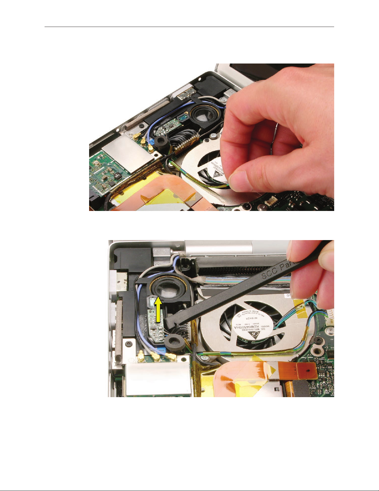
To remove the left ambient light sensor board:
Remove the Phillips screw and dust cover. Disconnect the connector on the logic board to
1.
the right of the fan.
To remove the JST connector, rmly sandwich the wires between your thumb and nger
2.
quite close to the connector and lift straight up.
MacBook Pro (15-inch Core 2 Duo) Take Apart — Ambient Light Sensors 83
Page 84
Peel the ALS cable away from the fan.
3.
Pry up the sensor board to release its adhesive and remove it from the speaker.
4.
MacBook Pro (15-inch Core 2 Duo) Take Apart — Ambient Light Sensors 84
Page 85

Fans
Tools
This procedure requires the following tools:
Torx T6 screwdriver (magnetized)
•
Black stick (nylon probe 922-5065) or other non-conductive nylon or plastic at-blade tool
•
Razor knife
•
Kapton tape (922-1731) (0.5-inch x 12-yard roll)
•
Preliminary Steps
Before you begin, remove the following:
Battery
•
Top Case
•
Part Location
MacBook Pro (15-inch Core 2 Duo) Take Apart — Fans 85
Page 86

To remove the left fan:
Remove three Torx T6 screws. Note the black screw in the right lower corner.
1.
Disconnect the four cable connectors shown.
2.
MacBook Pro (15-inch Core 2 Duo) Take Apart — Fans 86
Page 87

Carefully peel the ex cable o the fan cover.
3.
Use a razor knife to cut the length of the tape at the seam between the fan cover and the ns.
4.
Lift the fan from the right side rst to ease it out from underneath the left speaker bracket.
5.
MacBook Pro (15-inch Core 2 Duo) Take Apart — Fans 87
Page 88

To remove the right fan:
Peel up any Kapton tape, then use a razor knife to cut the length of the black tape—
1.
including the copper tape underneath—at the seam between the fan cover and the ns.
Disconnect the fan cable connector by holding the cable just next to the connector and
2.
gently tugging straight up. Remove the three Torx T6 screws shown below. Lift out the fan.
MacBook Pro (15-inch Core 2 Duo) Take Apart — Fans 88
Page 89

Replacement Procedure
After replacing either fan, apply new Kapton tape over the length of the cut tape to seal.
1.
Use Kapton tape to secure the iSight camera and inverter cable bundle (top) and the
2.
ambient light sensor cable bundle (bottom) to the left fan, if needed.
MacBook Pro (15-inch Core 2 Duo) Take Apart — Fans 89
Page 90

Logic Board
Tools
This procedure requires the following tools:
#0 Phillips screwdriver (magnetized)
•
Torx T6 screwdriver (magnetized)
•
Black stick (nylon probe 922-5065) or other non-conductive nylon or plastic at-blade tool
•
Multi-compartment screw tray (such as a plastic ice cube tray)
•
Kapton tape (922-1731) (0.5-inch x 12-yard roll)
•
Thermal grease (922-7144)
•
Gasket kit (076-1238)
•
Alcohol pads
•
Preliminary Steps
Before you begin, remove the following:
Battery
•
Memory
•
Top Case
•
Fans
•
Optical Drive
•
MacBook Pro (15-inch Core 2 Duo) Take Apart — Logic Board 90
Page 91

Part Location
Procedure
Disconnect the cables shown.. 1.
MacBook Pro (15-inch Core 2 Duo) Take Apart — Logic Board 91
Page 92

Tape the thermal sensor cable to the display assembly to avoid getting it trapped under the
2.
main logic board and forgetting it during reassembly.
Remove 11 Torx T6 screws.
3.
MacBook Pro (15-inch Core 2 Duo) Take Apart — Logic Board 92
Page 93

Warning: Do NOT allow the logic board to ex at any time. Flexing the board can crack
4.
solder joints to components. Give special attention at the narrow neck of the fan cutout.
From the left side of the board, slowly begin to lift the board, avoiding any exing, until the
5.
thermal material on the three chips underneath releases. Do not lift the board further.
Note: The thermal material should easily release. If not, verify that all screws and connectors
have been removed.
Remove the connector under the board, shown.
6.
Remove the logic board.
7.
Important: There are two metal shims on the under side of the logic board near the
graphics chip (screw holes 9 and 10 in the screw replacement order—see page 97). If reusing
this logic board, make sure those shims retain their position above the heat sink posts.
Warning: To avoid exing the logic board, hold the board vertically along the wide sides. Do
not hold the board by the ends or by the narrow neck at the fan cutout, or horizontally, as
the board’s weight can cause excessive ex.
MacBook Pro (15-inch Core 2 Duo) Take Apart — Logic Board 93
Page 94

Replacement Procedure
Verify that the EMI gaskets are in place along the port openings on the bottom case.
1.
If the logic board was removed to facilitate another procedure and will be reinstalled:
2.
• Use a black stick and alcohol wipes to clean the thermal grease from the three chips.
• Important: Use extreme care not to damage the chip or logic board components.
• Important: There are two metal shims on the under side of the logic board near the
graphics chip (screw holes 9 and 10 in the screw replacement order—see page 97).
Make sure those shims retain their position above the heat sink posts when replacing.
MacBook Pro (15-inch Core 2 Duo) Take Apart — Logic Board 94
Page 95

• Install EMI gaskets and tape on the ports from the gasket kit (076-1238).
• Transfer the logic board sleeves (922-7538) to the replacement board, if needed.
Transfer the cosmetic shield, if needed. •
MacBook Pro (15-inch Core 2 Duo) Take Apart — Logic Board 95
Page 96

The thermal material must be replaced using the following procedures.
1.
Warning: Whenever the logic board is separated from the heatsink, the thermal grease
must be replaced. Failure to do so can cause the computer to overheat and be damaged.
Use a black stick to remove as much thermal grease as possible from the heatsink.
2.
Use an alcohol wipe to clean the mating surface.
3.
Important: Avoid unnecessary contact with new thermal material, as dirt and body oils
reduce the material’s conductivity.
Note the contents of the syringe of thermal grease. Important: One syringe (922-7144)
4.
contains 0.3 to 0.35 cubic centimeters (cc) of thermal grease. That is enough for 0.1 to 0.12 cc
of grease per chip for up to three chips. Use one-third of the syringe contents per chip. Using
a felt-tip pen, mark the 1/3 points on the syringe before applying the rst dab. .
MacBook Pro (15-inch Core 2 Duo) Take Apart — Logic Board 96
Page 97

5.
Put a 0.1 - 0.12cc dab of thermal grease, in the center, on each chip mating surface, as shown.
6.
When replacing the logic board:
• Verify that the two plastic screw guides are installed on the top of the board.
• Guide the logic board’s port side into the port openings on the bottom case.
• Carefully lower the board over the right speaker, being aware of its exact placement to
avoid breakage along the delicate area where it narrows to the left side of the speaker.
• While lowering the board, connect the cable under the board on the left side.
• Verify that no cables are caught under the board when lowering into place.
• Important: Check for two metal shims on the under side of the logic board near the
graphics chip (screw holes 9 and 10 in the screw replacement order—see below). Make
sure those shims retain their position above the heat sink posts when replacing.
7.
Install the logic board screws in the order shown below.
MacBook Pro (15-inch Core 2 Duo) Take Apart — Logic Board 97
Page 98

Verify that the ExpressCard cage ex connector is seated properly. If the connector on the
1.
ex is not lined up with the connector on the logic board, a bad connection with a
characteristic bow, shown below, can occur.
Reassemble and test all ports, components and functions of the computer.
2.
Note: After installing new thermal material, if you must briey re-separate the logic board
from the heatsink, it is OK to retain the same, new thermal material, as long as it is not
handled excessively.
Important: Make sure the two metal shims on the under side of the logic board near the
graphics chip retain their position above the heat sink posts when replacing. See previous
page for specic locations.
MacBook Pro (15-inch Core 2 Duo) Take Apart — Logic Board 98
Page 99

Battery Cable Assembly
Tools
This procedure requires the following tools:
Torx T6 screwdriver (magnetized)
•
Black stick (nylon probe 922-5065) or other non-conductive nylon or plastic at-blade tool
•
Preliminary Steps
Before you begin, remove the following:
Battery
•
Top Case
•
AirPort Extreme Card
•
Right Ambient Light Sensor Lens
•
Speakers
•
Fans
•
Optical Drive
•
Logic Board
•
MacBook Pro (15-inch Core 2 Duo) Take Apart — Battery Cable Assembly 99
Page 100

Part Location
Procedure
Remove the two 8.5mm Torx T6 shoulder screws.. 1.
MacBook Pro (15-inch Core 2 Duo) Take Apart — Battery Cable Assembly 100
 Loading...