

Page 1
User Manual
pdu0393c
Serial
Network
10/100
by Schneider
Electric
Serial
by Schneider
Electric
Automatic
Transfer Switch
Reset
- Warning
- OK
- Overload
Network
10/100
USB
USB
Automatic
Transfer Switch
Reset
- Warning
- OK
- Overload
Rack Automatic Transfer Switch (ATS)
AP4421, AP4422, AP4423, AP4424, AP4430, AP4431, AP4432
AP4433, AP4434, AP4450, AP4452, AP4452J, AP4453
990-5844-001
Publication Date: 03/2017
Page 2

APC by Schneider Electric Legal Disclaimer
The information presented in this manual is not warranted by the APC by Schneider Electric to be authoritative,
error free, or complete. This publication is not meant to be a substitute for a detailed operational and site
specific development plan. Therefore, APC by Schneider Electric assumes no liability for damages, violations of
codes, improper installation, system failures, or any other problems that could arise based on the use of this
Publication.
The information contained in this Publication is provided as is and has been prepared solely for the purpose of
evaluating data center design and construction. This Publication has been compiled in good faith by APC by
Schneider Electric. However, no representation is made or warranty given, either express or implied, as to the
completeness or accuracy of the information this Publication contains.
IN NO EVENT SHALL APC BY SCHNEIDER ELECTRIC, OR ANY PARENT, AFFILIATE OR SUBSIDIARY
COMPANY OF APC by Schneider Electric OR THEIR RESPECTIVE OFFICERS, DIRECTORS, OR
EMPLOYEES BE LIABLE FOR ANY DIRECT, INDIRECT, CONSEQUENTIAL, PUNITIVE, SPECIAL, OR
INCIDENTAL DAMAGES (INCLUDING, WITHOUT LIMITATION, DAMAGES FOR LOSS OF BUSINESS,
CONTRACT, REVENUE, DATA, INFORMATION, OR BUSINESS INTERRUPTION) RESULTING FROM,
ARISING OUT, OR IN CONNECTION WITH THE USE OF, OR INABILITY TO USE THIS PUBLICATION OR
THE CONTENT, EVEN IF APC BY SCHNEIDER ELECTRIC HAS BEEN EXPRESSLY ADVISED OF THE
POSSIBILITY OF SUCH DAMAGES. APC BY SCHNEIDER ELECTRIC RESERVES THE RIGHT TO MAKE
CHANGES OR UPDATES WITH RESPECT TO OR IN THE CONTENT OF THE PUBLICATION OR THE
FORMAT THEREOF AT ANY TIME WITHOUT NOTICE.
Copyright, intellectual, and all other proprietary rights in the content (including but not limited to software, audio,
video, text, and photographs) rests with APC by Schneider Electric or its licensors. All rights in the content not
expressly granted herein are reserved. No rights of any kind are licensed or assigned or shall otherwise pass to
persons accessing this information.
This Publication shall not be for resale in whole or in part.
Page 3

Contents
Overview ..................................................................................................... 1
Product Features . . . . . . . . . . . . . . . . . . . . . . . . . . . . . . . . . . . . . . . . . . . . . . .1
Internal Protections . . . . . . . . . . . . . . . . . . . . . . . . . . . . . . . . . . . . . . . . . . . . .2
How Switching Works . . . . . . . . . . . . . . . . . . . . . . . . . . . . . . . . . . . . . . . . . . .2
Types of User Accounts . . . . . . . . . . . . . . . . . . . . . . . . . . . . . . . . . . . . . . . . .4
Getting Started . . . . . . . . . . . . . . . . . . . . . . . . . . . . . . . . . . . . . . . . . . . . . . . . .4
Establish Network Settings....................................................................... 5
IPv4 Initial Setup . . . . . . . . . . . . . . . . . . . . . . . . . . . . . . . . . . . . . . . . . . . . . . .5
IPv6 Initial Setup . . . . . . . . . . . . . . . . . . . . . . . . . . . . . . . . . . . . . . . . . . . . . . .5
TCP/IP Configuration Methods . . . . . . . . . . . . . . . . . . . . . . . . . . . . . . . . . . . .5
.ini file utility . . . . . . . . . . . . . . . . . . . . . . . . . . . . . . . . . . . . . . . . . . . . 5
Device IP Configuration Wizard . . . . . . . . . . . . . . . . . . . . . . . . . . . . 5
DHCP and BOOTP configuration . . . . . . . . . . . . . . . . . . . . . . . . . . . . 6
Local access to the CLI . . . . . . . . . . . . . . . . . . . . . . . . . . . . . . . . . . . 7
Remote access to the CLI . . . . . . . . . . . . . . . . . . . . . . . . . . . . . . . . . 8
Configure TCP/IP settings in the CLI . . . . . . . . . . . . . . . . . . . . . . . . 8
Network Management with Other Applications. . . . . . . . . . . . . . . . . . . . . . .9
Recover from a Lost Password . . . . . . . . . . . . . . . . . . . . . . . . . . . . . . . . . . .9
Watchdog Features . . . . . . . . . . . . . . . . . . . . . . . . . . . . . . . . . . . . . . . . . . . .10
Overview . . . . . . . . . . . . . . . . . . . . . . . . . . . . . . . . . . . . . . . . . . . . . . 10
Network interface watchdog mechanism . . . . . . . . . . . . . . . . . . . . 10
Resetting the network timer . . . . . . . . . . . . . . . . . . . . . . . . . . . . . . 10
Front Panel ............................................................................................... 11
Load Status LED . . . . . . . . . . . . . . . . . . . . . . . . . . . . . . . . . . . . . . . . 12
Network Status LED . . . . . . . . . . . . . . . . . . . . . . . . . . . . . . . . . . . . . 12
10/100 Status LED . . . . . . . . . . . . . . . . . . . . . . . . . . . . . . . . . . . . . . . 12
Front Panel Screens . . . . . . . . . . . . . . . . . . . . . . . . . . . . . . . . . . . . . . . . . . .13
Monitor Screens . . . . . . . . . . . . . . . . . . . . . . . . . . . . . . . . . . . . . . . . 13
Menu Screens . . . . . . . . . . . . . . . . . . . . . . . . . . . . . . . . . . . . . . . . . . 13
Command Line Interface ......................................................................... 14
Log on to the CLI . . . . . . . . . . . . . . . . . . . . . . . . . . . . . . . . . . . . . . . . . . . . . .14
Local access to the CLI . . . . . . . . . . . . . . . . . . . . . . . . . . . . . . . . . . 14
Remote access to the CLI . . . . . . . . . . . . . . . . . . . . . . . . . . . . . . . . 14
About the Main Screen . . . . . . . . . . . . . . . . . . . . . . . . . . . . . . . . . . . . . . . . .15
Rack ATS AP44xx User Manual i
Page 4

Using the CLI . . . . . . . . . . . . . . . . . . . . . . . . . . . . . . . . . . . . . . . . . . . . . . . . .16
Command Syntax. . . . . . . . . . . . . . . . . . . . . . . . . . . . . . . . . . . . . . . . . . . . . .17
Command Response Codes . . . . . . . . . . . . . . . . . . . . . . . . . . . . . . . . . . . . .18
Network Management Card Command Descriptions . . . . . . . . . . . . . . . . .19
? or help . . . . . . . . . . . . . . . . . . . . . . . . . . . . . . . . . . . . . . . . . . . . . . . 19
about . . . . . . . . . . . . . . . . . . . . . . . . . . . . . . . . . . . . . . . . . . . . . . . . . . 20
alarmcount . . . . . . . . . . . . . . . . . . . . . . . . . . . . . . . . . . . . . . . . . . . . . 21
boot . . . . . . . . . . . . . . . . . . . . . . . . . . . . . . . . . . . . . . . . . . . . . . . . . . . 22
cd . . . . . . . . . . . . . . . . . . . . . . . . . . . . . . . . . . . . . . . . . . . . . . . . . . . . 23
clrrst . . . . . . . . . . . . . . . . . . . . . . . . . . . . . . . . . . . . . . . . . . . . . . . . . . 23
console . . . . . . . . . . . . . . . . . . . . . . . . . . . . . . . . . . . . . . . . . . . . . . . . 23
date . . . . . . . . . . . . . . . . . . . . . . . . . . . . . . . . . . . . . . . . . . . . . . . . . . . 24
delete . . . . . . . . . . . . . . . . . . . . . . . . . . . . . . . . . . . . . . . . . . . . . . . . . 24
dir . . . . . . . . . . . . . . . . . . . . . . . . . . . . . . . . . . . . . . . . . . . . . . . . . . . . 25
dns . . . . . . . . . . . . . . . . . . . . . . . . . . . . . . . . . . . . . . . . . . . . . . . . . . . 26
email . . . . . . . . . . . . . . . . . . . . . . . . . . . . . . . . . . . . . . . . . . . . . . . . . . 27
eventlog . . . . . . . . . . . . . . . . . . . . . . . . . . . . . . . . . . . . . . . . . . . . . . . 28
exit, quit, or bye . . . . . . . . . . . . . . . . . . . . . . . . . . . . . . . . . . . . . . . . . 28
firewall . . . . . . . . . . . . . . . . . . . . . . . . . . . . . . . . . . . . . . . . . . . . . . . . 29
format . . . . . . . . . . . . . . . . . . . . . . . . . . . . . . . . . . . . . . . . . . . . . . . . . 29
ftp . . . . . . . . . . . . . . . . . . . . . . . . . . . . . . . . . . . . . . . . . . . . . . . . . . . . 30
lang . . . . . . . . . . . . . . . . . . . . . . . . . . . . . . . . . . . . . . . . . . . . . . . . . . . 30
lastrst . . . . . . . . . . . . . . . . . . . . . . . . . . . . . . . . . . . . . . . . . . . . . . . . . 31
ledblink . . . . . . . . . . . . . . . . . . . . . . . . . . . . . . . . . . . . . . . . . . . . . . . . 31
logzip . . . . . . . . . . . . . . . . . . . . . . . . . . . . . . . . . . . . . . . . . . . . . . . . . 31
netstat . . . . . . . . . . . . . . . . . . . . . . . . . . . . . . . . . . . . . . . . . . . . . . . . . 32
ntp . . . . . . . . . . . . . . . . . . . . . . . . . . . . . . . . . . . . . . . . . . . . . . . . . . . . 32
ping . . . . . . . . . . . . . . . . . . . . . . . . . . . . . . . . . . . . . . . . . . . . . . . . . . . 33
portSpeed . . . . . . . . . . . . . . . . . . . . . . . . . . . . . . . . . . . . . . . . . . . . . . 33
prompt . . . . . . . . . . . . . . . . . . . . . . . . . . . . . . . . . . . . . . . . . . . . . . . . 34
pwd . . . . . . . . . . . . . . . . . . . . . . . . . . . . . . . . . . . . . . . . . . . . . . . . . . . 34
radius . . . . . . . . . . . . . . . . . . . . . . . . . . . . . . . . . . . . . . . . . . . . . . . . . 35
reboot . . . . . . . . . . . . . . . . . . . . . . . . . . . . . . . . . . . . . . . . . . . . . . . . . 36
resetToDef . . . . . . . . . . . . . . . . . . . . . . . . . . . . . . . . . . . . . . . . . . . . . 36
session . . . . . . . . . . . . . . . . . . . . . . . . . . . . . . . . . . . . . . . . . . . . . . . . 37
smtp . . . . . . . . . . . . . . . . . . . . . . . . . . . . . . . . . . . . . . . . . . . . . . . . . . 38
snmp . . . . . . . . . . . . . . . . . . . . . . . . . . . . . . . . . . . . . . . . . . . . . . . . . . 39
snmpv3 . . . . . . . . . . . . . . . . . . . . . . . . . . . . . . . . . . . . . . . . . . . . . . . . 40
snmptrap . . . . . . . . . . . . . . . . . . . . . . . . . . . . . . . . . . . . . . . . . . . . . . 41
system . . . . . . . . . . . . . . . . . . . . . . . . . . . . . . . . . . . . . . . . . . . . . . . . 42
tcpip . . . . . . . . . . . . . . . . . . . . . . . . . . . . . . . . . . . . . . . . . . . . . . . . . . 43
tcpip6 . . . . . . . . . . . . . . . . . . . . . . . . . . . . . . . . . . . . . . . . . . . . . . . . . 44
user . . . . . . . . . . . . . . . . . . . . . . . . . . . . . . . . . . . . . . . . . . . . . . . . . . . 45
userdflt . . . . . . . . . . . . . . . . . . . . . . . . . . . . . . . . . . . . . . . . . . . . . . . . 46
web . . . . . . . . . . . . . . . . . . . . . . . . . . . . . . . . . . . . . . . . . . . . . . . . . . . 47
Rack ATS AP44xx User Manualii
Page 5

whoami . . . . . . . . . . . . . . . . . . . . . . . . . . . . . . . . . . . . . . . . . . . . . . . . 47
xferINI . . . . . . . . . . . . . . . . . . . . . . . . . . . . . . . . . . . . . . . . . . . . . . . . . 48
xferStatus . . . . . . . . . . . . . . . . . . . . . . . . . . . . . . . . . . . . . . . . . . . . . . 48
Device Command Descriptions . . . . . . . . . . . . . . . . . . . . . . . . . . . . . . . . . .49
aboutATS . . . . . . . . . . . . . . . . . . . . . . . . . . . . . . . . . . . . . . . . . . . . . . 49
atsStatus . . . . . . . . . . . . . . . . . . . . . . . . . . . . . . . . . . . . . . . . . . . . . . . 49
atsMeasure . . . . . . . . . . . . . . . . . . . . . . . . . . . . . . . . . . . . . . . . . . . . . 50
bkLowLoad . . . . . . . . . . . . . . . . . . . . . . . . . . . . . . . . . . . . . . . . . . . . . 50
bkNearOver . . . . . . . . . . . . . . . . . . . . . . . . . . . . . . . . . . . . . . . . . . . . . 51
bkOverLoad . . . . . . . . . . . . . . . . . . . . . . . . . . . . . . . . . . . . . . . . . . . . 52
bkPeakLoad . . . . . . . . . . . . . . . . . . . . . . . . . . . . . . . . . . . . . . . . . . . . 53
bkReading . . . . . . . . . . . . . . . . . . . . . . . . . . . . . . . . . . . . . . . . . . . . . . 54
eventCounts . . . . . . . . . . . . . . . . . . . . . . . . . . . . . . . . . . . . . . . . . . . . 54
freqDeviat . . . . . . . . . . . . . . . . . . . . . . . . . . . . . . . . . . . . . . . . . . . . . . 55
frontPanel . . . . . . . . . . . . . . . . . . . . . . . . . . . . . . . . . . . . . . . . . . . . . . 55
lcd . . . . . . . . . . . . . . . . . . . . . . . . . . . . . . . . . . . . . . . . . . . . . . . . . . . . 55
lcdBlink . . . . . . . . . . . . . . . . . . . . . . . . . . . . . . . . . . . . . . . . . . . . . . . . 56
lineVRMS . . . . . . . . . . . . . . . . . . . . . . . . . . . . . . . . . . . . . . . . . . . . . . 56
phLowLoad . . . . . . . . . . . . . . . . . . . . . . . . . . . . . . . . . . . . . . . . . . . . . 56
phNearOver . . . . . . . . . . . . . . . . . . . . . . . . . . . . . . . . . . . . . . . . . . . . 57
phOverLoad . . . . . . . . . . . . . . . . . . . . . . . . . . . . . . . . . . . . . . . . . . . . 57
phPeakLoad . . . . . . . . . . . . . . . . . . . . . . . . . . . . . . . . . . . . . . . . . . . . 57
phReading . . . . . . . . . . . . . . . . . . . . . . . . . . . . . . . . . . . . . . . . . . . . . 58
prodInfo . . . . . . . . . . . . . . . . . . . . . . . . . . . . . . . . . . . . . . . . . . . . . . . 58
sourceAName . . . . . . . . . . . . . . . . . . . . . . . . . . . . . . . . . . . . . . . . . . . 58
sourceBName . . . . . . . . . . . . . . . . . . . . . . . . . . . . . . . . . . . . . . . . . . . 59
sourcePref . . . . . . . . . . . . . . . . . . . . . . . . . . . . . . . . . . . . . . . . . . . . . 59
vMediumLmt . . . . . . . . . . . . . . . . . . . . . . . . . . . . . . . . . . . . . . . . . . . . 59
vNarrowLmt . . . . . . . . . . . . . . . . . . . . . . . . . . . . . . . . . . . . . . . . . . . . 60
vSensitvty . . . . . . . . . . . . . . . . . . . . . . . . . . . . . . . . . . . . . . . . . . . . . . 60
vWideLmt . . . . . . . . . . . . . . . . . . . . . . . . . . . . . . . . . . . . . . . . . . . . . . 61
vXferRange . . . . . . . . . . . . . . . . . . . . . . . . . . . . . . . . . . . . . . . . . . . . . 61
Web Interface ........................................................................................... 62
Log on to the Web Interface . . . . . . . . . . . . . . . . . . . . . . . . . . . . . . . . . . . . .62
URL address formats . . . . . . . . . . . . . . . . . . . . . . . . . . . . . . . . . . . . . 63
Web Interface Features . . . . . . . . . . . . . . . . . . . . . . . . . . . . . . . . . . . . . . . . .63
Tabs . . . . . . . . . . . . . . . . . . . . . . . . . . . . . . . . . . . . . . . . . . . . . . . . . . . 63
Device status icons . . . . . . . . . . . . . . . . . . . . . . . . . . . . . . . . . . . . . . 64
Quick Links . . . . . . . . . . . . . . . . . . . . . . . . . . . . . . . . . . . . . . . . . . . . . 64
Home Tab.................................................................................................. 65
Rack ATS AP44xx User Manual iii
Page 6

Status Tab................................................................................................. 66
View ATS Status. . . . . . . . . . . . . . . . . . . . . . . . . . . . . . . . . . . . . . . . . . . . . . .66
View device alarms . . . . . . . . . . . . . . . . . . . . . . . . . . . . . . . . . . . . . . 66
View device status . . . . . . . . . . . . . . . . . . . . . . . . . . . . . . . . . . . . . . . 66
View the unit status . . . . . . . . . . . . . . . . . . . . . . . . . . . . . . . . . . . . . . 66
View load status . . . . . . . . . . . . . . . . . . . . . . . . . . . . . . . . . . . . . . . . 66
View power measurements . . . . . . . . . . . . . . . . . . . . . . . . . . . . . . . 66
View Network Status . . . . . . . . . . . . . . . . . . . . . . . . . . . . . . . . . . . . . . . . . . .67
Current IPv4 settings . . . . . . . . . . . . . . . . . . . . . . . . . . . . . . . . . . . . 67
Current IPv6 settings . . . . . . . . . . . . . . . . . . . . . . . . . . . . . . . . . . . . 67
Domain name system status . . . . . . . . . . . . . . . . . . . . . . . . . . . . . . 68
Port Speed . . . . . . . . . . . . . . . . . . . . . . . . . . . . . . . . . . . . . . . . . . . . . 68
Control Tab............................................................................................... 69
Manage User Sessions . . . . . . . . . . . . . . . . . . . . . . . . . . . . . . . . . . . . . . . . .69
Reset the Network Interface . . . . . . . . . . . . . . . . . . . . . . . . . . . . . . . . . . . . .69
Configuration Tab .................................................................................... 70
Configure the ATS . . . . . . . . . . . . . . . . . . . . . . . . . . . . . . . . . . . . . . . . . . . . .70
Configure ATS name and location . . . . . . . . . . . . . . . . . . . . . . . . . . 70
Set preferred power source . . . . . . . . . . . . . . . . . . . . . . . . . . . . . . . 70
Configure switching behavior . . . . . . . . . . . . . . . . . . . . . . . . . . . . . 70
Configure warning thresholds . . . . . . . . . . . . . . . . . . . . . . . . . . . . . 71
Manage Security . . . . . . . . . . . . . . . . . . . . . . . . . . . . . . . . . . . . . . . . . . . . . .72
Manage user sessions . . . . . . . . . . . . . . . . . . . . . . . . . . . . . . . . . . . 72
Enable ping response . . . . . . . . . . . . . . . . . . . . . . . . . . . . . . . . . . . . 72
Manage local user settings . . . . . . . . . . . . . . . . . . . . . . . . . . . . . . . . 73
Configure default user settings . . . . . . . . . . . . . . . . . . . . . . . . . . . . 74
Manage remote user settings . . . . . . . . . . . . . . . . . . . . . . . . . . . . . . 75
RADIUS . . . . . . . . . . . . . . . . . . . . . . . . . . . . . . . . . . . . . . . . . . . . . . . . 76
Configure the RADIUS server . . . . . . . . . . . . . . . . . . . . . . . . . . . . . . 76
Supported RADIUS servers . . . . . . . . . . . . . . . . . . . . . . . . . . . . . . . 77
Configure firewalls . . . . . . . . . . . . . . . . . . . . . . . . . . . . . . . . . . . . . . 77
Configure Network Settings . . . . . . . . . . . . . . . . . . . . . . . . . . . . . . . . . . . . .79
Configure TCP/IP and communication settings for IPv4 and IPv6 79
Configure network port speed . . . . . . . . . . . . . . . . . . . . . . . . . . . . . 81
Configure DNS . . . . . . . . . . . . . . . . . . . . . . . . . . . . . . . . . . . . . . . . . . 82
Configure Web access . . . . . . . . . . . . . . . . . . . . . . . . . . . . . . . . . . . 83
Configure CLI access . . . . . . . . . . . . . . . . . . . . . . . . . . . . . . . . . . . . 84
SNMP options . . . . . . . . . . . . . . . . . . . . . . . . . . . . . . . . . . . . . . . . . . 85
SNMPv1 . . . . . . . . . . . . . . . . . . . . . . . . . . . . . . . . . . . . . . . . . . . . . . . 85
SNMPv3 . . . . . . . . . . . . . . . . . . . . . . . . . . . . . . . . . . . . . . . . . . . . . . . 86
Configure FTP server . . . . . . . . . . . . . . . . . . . . . . . . . . . . . . . . . . . . 87
Rack ATS AP44xx User Manualiv
Page 7

Configure Notifications . . . . . . . . . . . . . . . . . . . . . . . . . . . . . . . . . . . . . . . . .87
Configure notifications by event . . . . . . . . . . . . . . . . . . . . . . . . . . . 88
Configure notifications by group . . . . . . . . . . . . . . . . . . . . . . . . . . . 88
Set up e-mail notifications . . . . . . . . . . . . . . . . . . . . . . . . . . . . . . . . 89
SNMP traps . . . . . . . . . . . . . . . . . . . . . . . . . . . . . . . . . . . . . . . . . . . . . 92
Remote Monitoring Service . . . . . . . . . . . . . . . . . . . . . . . . . . . . . . . 93
General Configuration . . . . . . . . . . . . . . . . . . . . . . . . . . . . . . . . . . . . . . . . . .93
Configure identification . . . . . . . . . . . . . . . . . . . . . . . . . . . . . . . . . . . 93
Configure date, time, and daylight savings . . . . . . . . . . . . . . . . . . . 93
Create and import settings with the config file . . . . . . . . . . . . . . . . 94
Configure links . . . . . . . . . . . . . . . . . . . . . . . . . . . . . . . . . . . . . . . . . . 95
Configure Logs. . . . . . . . . . . . . . . . . . . . . . . . . . . . . . . . . . . . . . . . . . . . . . . .95
Identify Syslog servers . . . . . . . . . . . . . . . . . . . . . . . . . . . . . . . . . . . 95
Configure Syslog settings . . . . . . . . . . . . . . . . . . . . . . . . . . . . . . . . 95
Test Syslog servers . . . . . . . . . . . . . . . . . . . . . . . . . . . . . . . . . . . . . . 96
Tests Tab .................................................................................................. 97
Set the LCD/LED Lights to Blink. . . . . . . . . . . . . . . . . . . . . . . . . . . . . . . . . .97
Set the LED Lights to Blink . . . . . . . . . . . . . . . . . . . . . . . . . . . . . . . . . . . . . .97
Logs Tab................................................................................................... 98
View and configure the Event Log . . . . . . . . . . . . . . . . . . . . . . . . . . . . . . . .98
View and configure the Data Log . . . . . . . . . . . . . . . . . . . . . . . . . . . . . . . .100
Firewall log . . . . . . . . . . . . . . . . . . . . . . . . . . . . . . . . . . . . . . . . . . . . 101
Use FTP or SCP to retrieve log files . . . . . . . . . . . . . . . . . . . . . . . . 101
About Tab ............................................................................................... 103
About the Rack ATS. . . . . . . . . . . . . . . . . . . . . . . . . . . . . . . . . . . . . . . . . . .103
About the network . . . . . . . . . . . . . . . . . . . . . . . . . . . . . . . . . . . . . . . . . . . .103
Support resources . . . . . . . . . . . . . . . . . . . . . . . . . . . . . . . . . . . . . . . . . . . .103
How to Export Configuration Settings................................................. 104
Summary of the procedure . . . . . . . . . . . . . . . . . . . . . . . . . . . . . . . . . . . . .104
Contents of the .ini file . . . . . . . . . . . . . . . . . . . . . . . . . . . . . . . . . . . . . . . .104
Detailed procedures. . . . . . . . . . . . . . . . . . . . . . . . . . . . . . . . . . . . . . . . . . .104
Retrieve .ini file . . . . . . . . . . . . . . . . . . . . . . . . . . . . . . . . . . . . . . . . 104
Edit .ini file . . . . . . . . . . . . . . . . . . . . . . . . . . . . . . . . . . . . . . . . . . . . 105
Transfer the file to a single ATS . . . . . . . . . . . . . . . . . . . . . . . . . . . 105
Transfer the file to multiple ATSs . . . . . . . . . . . . . . . . . . . . . . . . . . 105
The Upload Event and Error Messages . . . . . . . . . . . . . . . . . . . . . . . . . . .106
The event and its error messages . . . . . . . . . . . . . . . . . . . . . . . . . 106
Messages in config.ini . . . . . . . . . . . . . . . . . . . . . . . . . . . . . . . . . . . 106
Errors generated by overridden values . . . . . . . . . . . . . . . . . . . . . 106
Rack ATS AP44xx User Manual v
Page 8

Related Topics . . . . . . . . . . . . . . . . . . . . . . . . . . . . . . . . . . . . . . . . . . . . . . .106
File Transfers ......................................................................................... 107
Upgrading Firmware . . . . . . . . . . . . . . . . . . . . . . . . . . . . . . . . . . . . . . . . . .107
Benefits of upgrading firmware . . . . . . . . . . . . . . . . . . . . . . . . . . . 107
Firmware module files . . . . . . . . . . . . . . . . . . . . . . . . . . . . . . . . . . . 107
Firmware File Transfer Methods. . . . . . . . . . . . . . . . . . . . . . . . . . . . . . . . .107
Use the Firmware Upgrade Utility . . . . . . . . . . . . . . . . . . . . . . . . . 108
Use FTP or SCP to upgrade one Rack ATS . . . . . . . . . . . . . . . . . . 108
Use XMODEM to upgrade one Rack ATS . . . . . . . . . . . . . . . . . . . 109
Use a USB drive to transfer and upgrade files . . . . . . . . . . . . . . . 109
How to upgrade multiple ATSs . . . . . . . . . . . . . . . . . . . . . . . . . . . . 110
Use the Firmware Upgrade Utility for multiple upgrades . . . . . . 110
Verifying Upgrades and Updates . . . . . . . . . . . . . . . . . . . . . . . . . . . . . . . .111
Verify the success or failure of the transfer . . . . . . . . . . . . . . . . . 111
Last Transfer Result codes . . . . . . . . . . . . . . . . . . . . . . . . . . . . . . 111
Verify the version numbers of installed firmware . . . . . . . . . . . . 111
Troubleshooting..................................................................................... 112
Rack ATS Access Problems . . . . . . . . . . . . . . . . . . . . . . . . . . . . . . . . . . . .112
SNMP Issues . . . . . . . . . . . . . . . . . . . . . . . . . . . . . . . . . . . . . . . . . . . . . . . .113
Source Code Copyright Notice............................................................. 114
Rack ATS AP44xx User Manualvi
Page 9

Overview
The APC by Schneider Electric™ Rack Automatic Transfer Switch (ATS) provides reliable, redundant
power to single-corded equipment loads, such as servers. The Rack ATS has two input power cords
supplying power to the connected loads from both a primary and secondary power source. If the primary
source becomes unavailable or goes out of the configured power range, the Rack ATS will switch to
draw power from the secondary source without interrupting critical loads. You can manage a Rack ATS
through its web interface, its command line interface (CLI), StruxureWare™ Data Center Expert, or
Simple Network Management Protocol (SNMP). (To use the PowerNet® MIB with an SNMP browser,
see the PowerNet SNMP Management Information Base (MIB) Reference Guide, available at
www.apc.com.)
Product Features
The Rack ATS has these additional features:
• LED indicators on the front panel of the unit indicate operation conditions such as preferred
source, overload current, and web connectivity. These conditions can also be monitored via the
command line interface (CLI) and web interface.
• Various levels of access: Super User, Administrator, Device User, Read-Only, and Network-Only
User (These are protected by user name and password requirements).
• A multiple-user login feature, which allows up to four users to be logged in simultaneously.
• Event and data logging. The event log is accessible by Telnet, Secure CoPy (SCP), File Transfer
Protocol (FTP), serial connection, or web browser (using HTTPS access with SSL, or using HTTP
access). The data log is accessible by web browser, SCP, or FTP.
• SNMP traps, Syslog messages, and e-mail notifications based on the severity level or category of
the Rack ATS and NMC system event.
• Security protocols for authentication and encryption.
• The ability to monitor sources and set source-transfer parameters via web and CLI interfaces.
• Set alarm thresholds that provide network and visual alarms to help you prevent overloaded
circuits.
• Internal protection against short circuits. (See “Internal Protections” on page 2 for details.)
NOTE: It is always recommended that you connect each ATS source to a Double Conversion
On-Line Uninterruptible Power Supply (UPS).
1Rack ATS AP44xx User Manual
Page 10
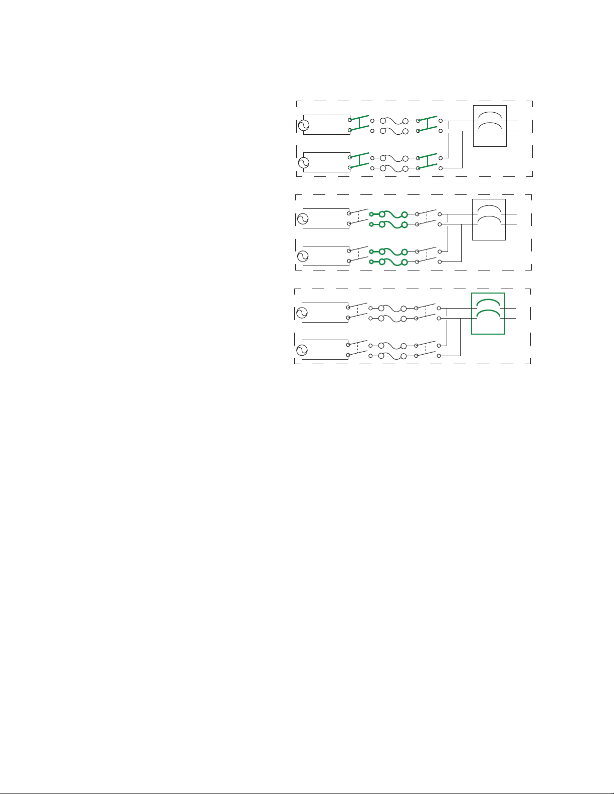
Internal Protections
pdu0777a
Source A
Source B
Load
ATS 1
Source A
Source B
Load
ATS 2
Source A
Source B
Load
ATS 3
ATS models may include the following internal protections:
• Input relays in every model open
when their source is disconnected to
prevent electric backfeed from one
input cord into another (ATS 1).
• Two or four non-replaceable fuses
(depending on the model) protect the
ATS from short circuits (ATS 2).
• Some 2U models have circuit
breakers for bank overload
protection (ATS 3).
The rack ATS does not include power surge protection. To protect your ATS from external power surges,
it is always recommended that you connect each ATS source to a Double Conversion On-Line
Uninterruptible Power Supply (UPS).
How Switching Works
1. You configure the ATS to accept power that meets the needs of your equipment by adjusting the
following settings (see “Configuration Tab” on page 70 for more details).
– Line VRMS: the ideal voltage for your equipment. Acceptable line voltages vary per ATS
model and can be found on your ATS specification sheet (visit www.apc.com).
– Transfer limits: The maximum and minimum voltages the ATS will accept before switching to
the other source. These are meant to allow for small, acceptable surges and drops in power.
The ATS should not run near the upper transfer limit for long periods of time.
– Transfer ranges: Pre-defined sets of transfer limits. You can configure up to three transfer
ranges.
– Sensitivity: How long the ATS waits to determine whether or not it will switch sources.
High sensitivity provides extra responsiveness for delicate equipment. Low sensitivity prevents
excessive switching in cases of fluctuating power inputs.
Rack ATS AP44xx User Manual2
Page 11
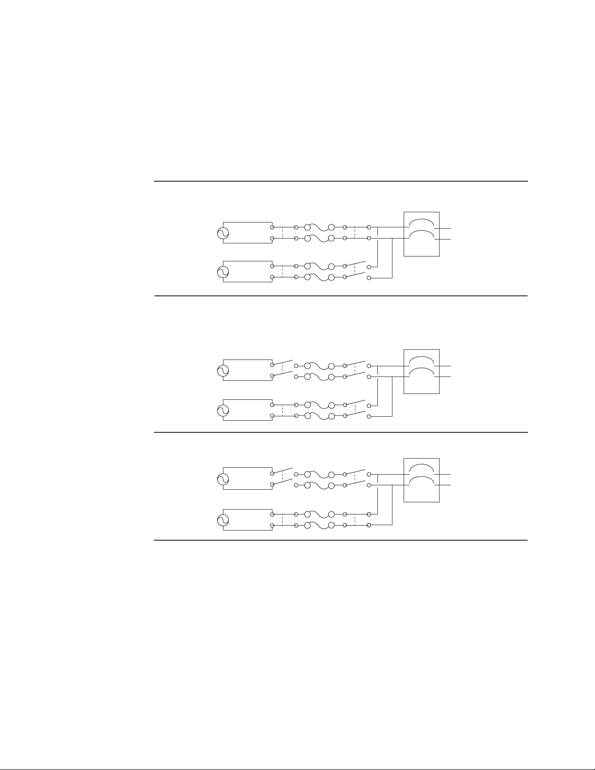
2. The ATS constantly monitors the quality and amount of power coming from sources A and B. If
pdu0776a
Source A
Source B
Attached Equipment
Source A
Source B
Attached Equipment
Source A
Source B
Attached Equipment
Source A is providing power to the attached equipment, while Source B is isolated from
the attached equipment.
Firmware detects that Source A is out of the user-specified transfer range. The input
power from Source A is removed by disengaging the relays. (This allows for
out-of-phase switching and significantly reduces the opportunity for relay welding.)
Source B relays are engaged; Source B provides power to the attached equipment.
one source begins to supply power that does not meet your settings, the ATS will disqualify that
source.
a. If the disqualified source is not in use, the ATS will generate an alarm indicating
redundancy has been lost.
b. If the disqualified source is in use, the ATS will switch to draw power from the other
available source.
c. If a preferred source is set, the ATS will wait 30 seconds to monitor that source. After 30
seconds, if the preferred source become stable again, the ATS will switch back to the
preferred source. Below is an illustration of how the switch happens
NOTE: The entire switching process (described in step 2) takes a maximum of 10
milliseconds (ms) at high sensitivity, and 12 ms at low sensitivity.
3Rack ATS AP44xx User Manual
Page 12

Types of User Accounts
The Rack ATS has various levels of access (Super User, Administrator, Device User, Read-Only User,
and Network-Only User), which are protected by user name and password requirements. Up to four
users are allowed to log on to the same Rack ATS simultaneously (available in AOS version 6.1.3 or
later).
• An Administrator or the Super User can use all of the menus in the web interface and all of the
commands in the CLI. Administrator user types can be deleted, but the Super User cannot be
deleted. The default user name and password for the Super User or an Administrator are both
apc.
– The Super User or an Administrator can manage another Administrator's account (enable,
disable, change password, etc).
• A Device User has read and write access to device-related screens. Administrative functions like
Session Management under the Security menu and Firewall under Logs are unavailable.
• A Read-Only User has access to the same menus as a Device User, but without the ability to
change configurations, control devices, delete data, or use file transfer options. Links to
configuration options are visible but disabled. The event and data logs display no button to clear
the log.
A Network-Only User can only log on using the web interface and CLI (telnet, not serial). A NetworkOnly User has read/wright access to the network related menus only.
Getting Started
To start using the Rack ATS:
1. Install the Rack ATS using the Installation and Quick Start on www.apc.com.
2. Apply power and connect to your network. Follow the directions in the Installation and Quick
Start.
3. Establish your network settings.
4. Begin using the Rack ATS with one of the following:
– The front panel. See “Front Panel” on page 11.
NOTE: The front panel allows you to view Rack ATS settings, but not configure them.
– The CLI. See “Command Line Interface” on page 14.
– The web interface. See “Web Interface” on page 62.
Rack ATS AP44xx User Manual4
Page 13

Establish Network Settings
IPv4 Initial Setup
You must define three TCP/IP settings for the Rack ATS before it can operate on the network:
• The IP address of the Rack ATS
• The subnet mask of the Rack ATS
• The IP address of the default gateway (only needed if you are going off segment)
Caution: Do NOT use the loopback address (127.0.0.1) as the default gateway. Doing so disables the
network connection of the Rack ATS. To enable again, you must log on using a serial connection and
reset the TCP/IP settings to their defaults.
For detailed information on how to use a DHCP server to configure the TCP/IP settings at a Rack ATS,
see.“DHCP response options” on page 79
IPv6 Initial Setup
IPv6 network configuration provides flexibility to accommodate your requirements. IPv6 can be used
anywhere an IP address is entered on this interface. You can configure IPv6 using the CLI, the web
interface, or DHCP.
TCP/IP Configuration Methods
Use one of the following methods to define the TCP/IP settings needed by the Rack ATS:
• Device IP Configuration Wizard (see “Device IP Configuration Wizard” on this page).
• BOOTP or DHCP server (see “DHCP and BOOTP configuration” on page 6).
• Local computer (see “Local access to the CLI” on page 7).
• Networked computer (see “Remote access to the CLI” on page 8).
.ini file utility
You can use the .ini file export utility to export .ini file settings from a configured Rack ATS to an
unconfigured Rack ATS. For more information, see “Create and import settings with the config file” on
page 94.
Device IP Configuration Wizard
The Device IP Configuration Wizard runs on Microsoft® Windows® 2000, Windows Server® 2003,
Windows Server 2012, and on 32- and 64-bit versions of Windows XP
2008, Windows 7, Windows 8, and Windows 10 operating systems. The Device IP Configuration Wizard
supports cards that have firmware version 3.0.x or higher and is for IPv4 only.
To install the Device IP Configuration Wizard:
1. Go to www.apc.com.
2. Download the latest version of the Device IP Configuration Wizard.
3. Run the executable file (DeviceIPConfigurationWizard.exe).
NOTE: If you leave the Start a Web browser when finished option enabled, you can use apc
for both the user name and password to access the Rack ATS through your browser.
®
, Windows Vista®, Windows
When Installed, the Device IP configuration Wizard is available through the Windows Start menu
options.
5Rack ATS AP44xx User Manual
Page 14

Configure TCP/IP settings with the Wizard. : The Device IP Configuration Wizard can discover Rack
ATSs that do not have an IP address assigned. Once discovered, you can configure the IP address
settings for the Network Management Cards (NMCs).You can also search for devices already on the
network by entering an IP range to define the search. The Utility scans the IP addresses in the defined
range and discovers Rack ATSs that already have a DHCP-assigned IP address.
NOTE: For detailed information on the Utility, visit the Knowledge Base on the support page on
www.apc.com and search for FA156064 (the ID of the relevant article).
NOTE: To use the DHCP Option 12 (AOS 5.1.5 or higher), see Knowledge Base ID FA156110.
DHCP and BOOTP configuration
The default TCP/IP configuration setting, DHCP, assumes that a properly configured DHCP server is
available to provide TCP/IP settings to the Rack ATS. You can also configure the setting for BOOTP.
A user configuration (INI) file can function as a BOOTP or DHCP boot file. For more information, see
“Create and import settings with the config file” on page 94.
If neither of these servers is available, see “Device IP Configuration Wizard” on page 5.
BOOTP. : For the Rack ATS to use a BOOTP server to configure its TCP/IP settings, it must find a
properly configured RFC951-compliant BOOTP server.
1. In the BOOTPTAB file of the BOOTP server, enter the Rack ATS’s MAC address, IP address,
subnet mask, and default gateway, and, optionally, a bootup file name. Look for the MAC address
on the bottom of the Rack ATS.
2. When the Rack ATS reboots, the BOOTP server provides it with the TCP/IP settings.
– If you specified a bootup file name, the Rack ATS attempts to transfer that file from the
BOOTP server using TFTP or FTP. The Rack ATS assumes all settings specified in the bootup
file.
– If you did not specify a bootup file name, you can configure the other settings of the Rack ATS
remotely through its web interface (see “Web Interface” on page 62) or CLI (see “Remote
access to the CLI” on page 8) The default user name and password are apc for both
interfaces. To create a bootup file, see your BOOTP server documentation.
Rack ATS AP44xx User Manual6
Page 15

DHCP. You can use an RFC2131/RFC2132-compliant DHCP server to configure the TCP/IP settings for
the Rack ATS.
1. The Rack ATS sends out a DHCP request that uses the following to identify itself:
– A Vendor Class Identifier (APC by default)
– A Client Identifier (by default, the MAC address of the Rack ATS)
– A User Class Identifier (by default, the identification of the application firmware installed on the
Rack ATS)
– A Host Name (by default, apcXXYYZZ with XXYYZZ being the last six digits of the ATS serial
number). This is known as DHCP Option 12.
2. A properly configured DHCP server responds with a DHCP offer that includes all the settings that
the Rack ATS needs for network communication. The DHCP offer also includes the Vendor
Specific Information option (DHCP option 43). The Rack ATS can be configured to ignore DHCP
offers that do not encapsulate the APC cookie in DHCP option 43 using the following
hexadecimal format. (The Rack ATS does not require this cookie by default.)
Option 43 = 01 04 31 41 50 43
– The first byte (01) is the code.
– The second byte (04) is the length.
– The remaining bytes (31 41 50 43) are the APC cookie.
See your DHCP server documentation to add code to the Vendor Specific Information option.
NOTE: By selecting the Require vendor specific cookie to accept DHCP Address check
box in the web interface, you can require the DHCP server to provide an “APC” cookie, which
supplies information to the Rack ATS.
Local access to the CLI
You can use a local computer to connect to the ATS and access the CLI.
1. Select a serial port at the local computer and disable any service that uses that port.
2. Use the communication cable to connect the selected port to the serial port on the front panel of
the ATS.
3. Run a terminal program (such as HyperTerminal®) and configure the selected port for 9600 bps,
8 data bits, no parity, 1 stop bit, and no flow control. Save the changes.
4. Press
5. Use apc for the user name and password.
6. See “Configure TCP/IP settings in the CLI” on page 8 to finish the configuration.
ENTER up to 3 times to display the User Name prompt.
7Rack ATS AP44xx User Manual
Page 16

Remote access to the CLI
From any computer on the same network as the Rack ATS, you can use ARP and Ping to assign an IP
address to the Rack ATS, and then use Telnet to access the CLI of that Rack ATS and configure the
other TCP/IP settings.
NOTE: After the IP address of the Rack ATS is configured, you can access the Rack ATS using Telnet or
SSH, without first using ARP and Ping. You must enable SSH before using it, so Telnet is required for
initial CLI configuration.
1. Use ARP to define an IP address for the Rack ATS and use the MAC address of the Rack ATS in
the ARP command. For example, to define an IP address of 156.205.14.141 for a Rack ATS that
has a MAC address of 00 c0 b7 63 9f 67, use one of the following commands:
– Windows command format:
arp -s 156.205.14.141 00-c0-b7-63-9f-67
– LINUX command format:
arp -s 156.205.14.141 00:c0:b7:63:9f:67
NOTE: The MAC address can be found on the bottom of the ATS.
2. Use Ping with a size of 113 bytes to assign the IP address defined by the ARP command. For
example:
– Windows command format:
ping 156.205.14.141 -l 113
– LINUX command format:
ping 156.205.14.141 -s 113
3. Use Telnet to access the Rack ATS at its newly assigned IP address. (For example:
telnet 156.205.14.141) Use apc for both user name and password.
(See “Remote access to the CLI” on page 14)
See “Configure TCP/IP settings in the CLI” on page 8 to finish the configuration.
Configure TCP/IP settings in the CLI
1. Log on to the CLI. See “Log on to the CLI” on page 14.
2. Contact your network administrator to obtain the IP address, subnet mask, and default gateway
for the Rack ATS.
3. Use these three commands to configure network settings. (Text in italics indicates a variable.)
tcpip -i yourIPaddress
tcpip -s yourSubnetMask
tcpip -g yourDefaultGateway
For each variable, type a numeric value that has the format xxx.xxx.xxx.xxx. For example,
to set a system IP address of 156.205.14.141, type the following command and press
tcpip -i 156.205.14.141
4. Type exit, and then press
ENTER. The Rack ATS restarts to apply the changes.
ENTER:
Rack ATS AP44xx User Manual8
Page 17

Network Management with Other Applications
These applications and utilities work with a Rack ATS that is connected to the network.
• PowerNet
SETs and GETs and use SNMP traps
• StruxureWare Data Center Expert — Provide enterprise-level power management and
management of agents, Rack ATSs, and environmental monitors.
• Device IP Configuration Utility — Configure the basic settings of one or more Rack ATSs over the
network (see “Device IP Configuration Utility”).
• Security Wizard — Create components needed to help with security for the Rack ATSs when you
are using Secure Sockets Layer (SSL) and related protocols and encryption routines.
Management Information Base (MIB) with a standard MIB browser — Perform SNMP
Recover from a Lost Password
You can use a local computer (a computer that connects to the Rack ATS through the serial port) to
access the command line interface.
1. Select a serial port at the local computer, and disable any service that uses that port.
2. Connect the serial cable (APC by Schneider Electric part number 940-0144A) to the selected port
on the computer and to the Serial port on the Rack ATS.
3. Run a terminal program (such as HyperTerminal
8 data bits, no parity, 1 stop bit, and no flow control.
4. Press
5. Press the Reset button. The Status LED will flash alternately orange and green within 5 to 7
6. Press
7. At the command line interface, use the following commands to change the Password from apc
8. Type quit or exit, and then press
9. Reconnect any serial cable you disconnected, and restart any service you disabled.
ENTER up to 3 times to display the User Name prompt. If you are unable to display the
User Name prompt, verify the following:
– The serial port is not in use by another application.
– The terminal settings are correct as specified in step 3.
– The correct cable is being used as specified in step 2.
seconds of pressing the Reset button. When the LED begins flashing, immediately press the
Reset button a second time to temporarily reset the user name and password to their defaults.
ENTER, repeatedly if necessary, to display the User Name prompt again, then use apc, for
the user name and password. (If you take longer than 30 seconds to log on after the User Name
prompt is re-displayed, you must repeat step 5 and log on again.)
to a password of your choice:
user -n <user name> -pw <user password>
For example, to change the Super User password to XYZ type:
user -n apc -cp apc -pw XYZ
ENTER to log off.
®
) and configure the selected port for 9600 bps,
9Rack ATS AP44xx User Manual
Page 18

Watchdog Features
Overview
To detect internal problems and recover from unanticipated inputs, the Rack ATS uses internal, systemwide watchdog mechanisms. When it restarts to recover from an internal problem, a Network Interface
Restarted event is recorded in the event log.
Network interface watchdog mechanism
The Rack ATS implements internal watchdog mechanisms to protect itself from becoming inaccessible
over the network. For example, if the Rack ATS does not receive any network traffic for 9.5 minutes
(either direct traffic, such as SNMP, or broadcast traffic, such as an Address Resolution Protocol [ARP]
request), it assumes that there is a problem with its network interface and restarts. The network interface
watchdog mechanism is only enabled on an ATS that discovers an active network interface connection
at start-up.
Resetting the network timer
To ensure that the Rack ATS does not restart if the network is quiet for 9.5 minutes, the Rack ATS
attempts to contact the default gateway every 4.5 minutes. If the gateway is present, it responds to the
Rack ATS, and the response restarts the 9.5-minute timer. If your application does not require or have a
gateway, specify the IP address of a computer that is running on the network and is on the same subnet.
The network traffic of that computer will restart the 9.5-minute time frequently enough to prevent the
Rack ATS from restarting.
Rack ATS AP44xx User Manual10
Page 19
Front Panel
Serial
10 /100
USB
Preference
A/B
Automatic
Transfer Switch
B
1
4
78
:
2
35
6
<
=
>
9;
- OK
- Warning
- Overload
x
Reset
NOTE: Your Rack ATS is configured so the display back light turns off after 10 minutes of inactivity.
Press any display navigation button to illuminate the back light.
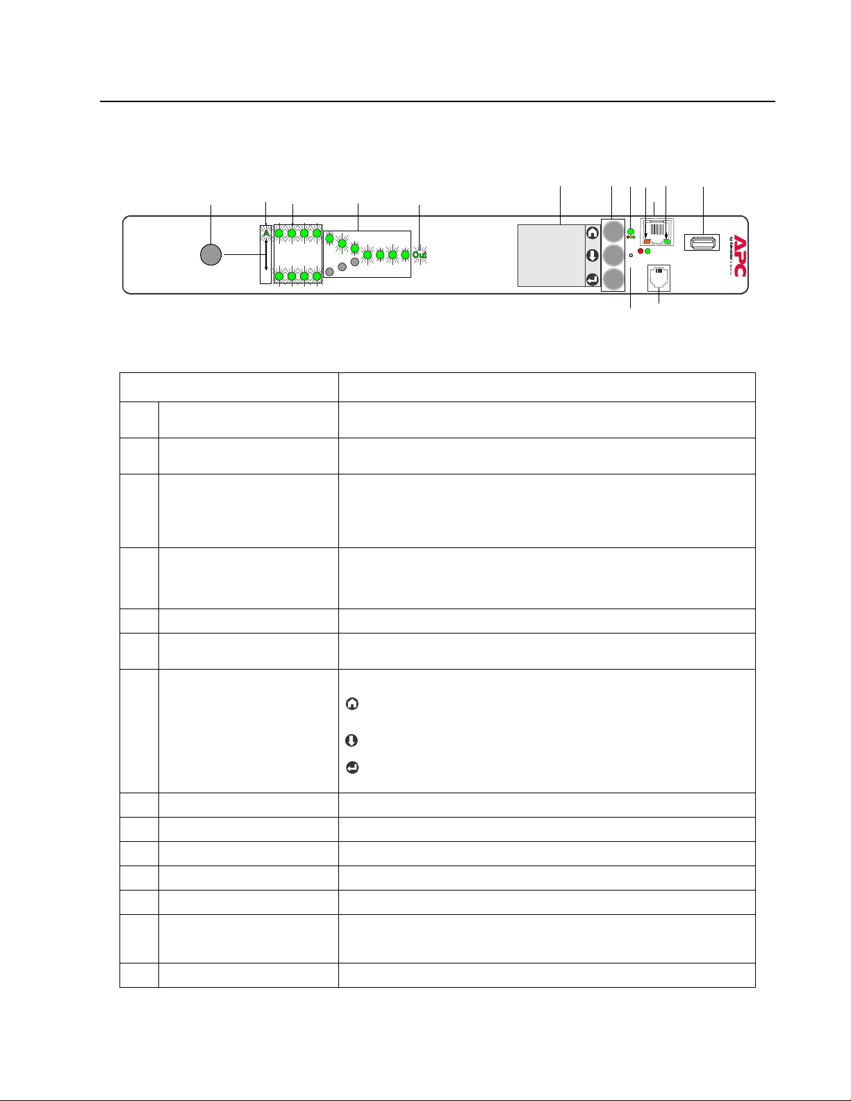
Item Function
Preference A/B Button Press to set a preferred source: the first press sets source A, the second
Source A and B LEDs Indicate preferred source. If no source is preferred, both LEDs are
Input Connector LEDs Provide information about input voltage from each source. If the RMS
Output Connector LEDs Indicate which source is being used for the output (only one path will be
Output LED Shows that voltage is available at the output of the ATS.
LCD Display View ATS status, settings, and product information. See “Front Panel
Display navigation buttons On the LCD Display, icons indicate the purpose of adjacent buttons.
press sets source B, and the third press sets no preference.
illuminated. You can also see preferred source on the LCD Display.
input voltage and measured frequency are within the selected tolerance
range, the corresponding indicator will be illuminated. In a normal
operating condition (full source redundancy) both sets of LEDs are
illuminated.
illuminated at any time). Together, the Source Preference LEDs, the
Connector LEDs, and the Output LED show the power flow through the
ATS .
Screens” on page 13 for more information on LCD display screens.
Home: Press to move through monitor screens or return to monitor
screens from sub-menus.
Netwo rk
pdu0733b
Down: Press to move through monitor screens or menu items.
Select: Press to select menu items or navigate to the main menu from
monitor screens.
Load Status LED See “Load Status LED” on page 12
Network Status LED See “Network Status LED” on page 12
10/100 Base-T Connector Connects the ATS to the network.
10/100 Status LED See “10/100 Status LED” on page 12.
USB port Use USB drives for firmware upgrades.
Serial port Connect your computer to the ATS for local access to the command line
Reset switch Restarts ATS network and serial communication.
interface. Use the supplied Serial Communication cable (APC by
Schneider Electric part number 940-0144A).
11Rack ATS AP44xx User Manual
Page 20

Load Status LED
This LED identifies overload and warning conditions for the ATS. For more information on warning
conditions, see “Configure warning thresholds” on page 71.
Condition Description
Green The Rack ATS current is below the Near Overload Warning threshold.
Yellow The Rack ATS current is above the Near Overload Warning threshold.
Red The Rack ATS current is above the Overload Alarm threshold.
Network Status LED
This LED indicates the network status.
Condition Description
Off The device that connects the Rack ATS to the network is off or not
Flashing Green The Rack ATS is receiving data packets from the network at 10 Megabits
Flashing Orange The Rack ATS is receiving data packets from the network at 100
Solid Green or Orange The Rack ATS is receiving no network traffic.
operating correctly.
per second (Mbps).
Megabits per second (Mbps).
10/100 Status LED
This LED indicates the network status of the Rack ATS.
Condition Description
Off The Rack ATS is connected to an unknown network.
Solid green The Rack ATS has valid TCP/IP settings.
Flashing green The Rack ATS does not have valid TCP/IP settings.
Solid orange A hardware failure has been detected in the Rack ATS.
Flashing orange The Rack ATS is making BOOTP requests.
Flashing Orange
and Green
(alternating)
1
If you do not use a BOOTP or DHCP server, see “TCP/IP Configuration Methods” on
page 5 for more options.
The Rack ATS is making DHCP requests.
1
Rack ATS AP44xx User Manual12
Page 21

Front Panel Screens
The front panel LCD Display automatically rotates between 4 monitor screens. You can move through
these screens manually by pressing Home or Down , or go to the Main Menu by pressing Select
.
Monitor Screens
Load Status (color): View the total ATS load in amps. A status symbol next to the total load indicates
the status of the ATS (see “Device status icons” on page 64). Meters show the load for the ATS (T) and
for individual banks (1, 2).The placement of the vertical line on colored meters indicates the current load
status:
• green = normal
• yellow = near overload
• red = overload
NOTE: If a low load threshold was configured, meters will also include a blue segment to indicate low
load.
Source Status: View power measurements for both sources. The active power source is green, and the
preferred source has a checked box next to it. When alarms happen, an Alarm Status bar will appear
across the top of this screen.
Load Status (no color): Meters indicate the amount of available load being used in the ATS (T) and in
individual banks (1, 2). The total load is also listed in Amperes (A). A status symbol next to the total load
indicates the status of the ATS (see “Device status icons” on page 64).
Preferred Source: The preferred power source is green, and the secondary source is black. When
alarms happen, an Alarm Status bar will appear across the top of the screen.
Menu Screens
When alarms are present, an Alarm Status bar will appear across the top of all menu screens. After 30
seconds without activity, the LCD display will revert to the main Monitor Screens.
Feed Info: Select Feed A or B to view available power for each power source. Select Preferred Source
to view ATS Preference settings (the preferred source will be green).
Network: View IPv4 address, press Down once to view the IPv6 address, or press Down twice to
view the MAC address.
Software Info: View the installed versions of AOS, APP, and ATS Controller.
SKU/Serial#: View the SKU number and serial number for your Rack ATS.
Alarm Status: View the number of each kind of alarm. If a down arrow is present at the bottom of the
screen, press Down for more detail. Otherwise, press Down to refresh the screen. If an alarm has
been cleared and no alarms are present, the Alarm Status screen will say “All Alarms Cleared”.
13Rack ATS AP44xx User Manual
Page 22

Command Line Interface
You can use the command line interface (CLI) to configure, manage, and monitor the status of the Rack
ATS. Additionally, the CLI enables you to create scripts for automated operation. You can configure all
parameters of a Rack ATS (including those for which there are not specific CLI commands) by using the
CLI to transfer an INI file to the Rack ATS. The CLI uses XMODEM to perform the transfer. However, you
cannot read the current INI file through XMODEM.
Log on to the CLI
To access the command line interface, you can use either a local (serial) connection or a remote (Telnet
or SSH) connection with a computer on the same network as the Rack ATS.
Local access to the CLI
For local access, use a computer that connects to the Rack ATS through the serial port to access the
CLI:
1. Select a serial port at the computer and disable any service that uses that port.
2. Connect the serial cable (APC by Schneider Electric part number 940-0144A) from the selected
serial port on the computer to the Serial port on the Rack ATS.
3. Run a terminal program (e.g., HyperTerminal) and configure the selected port for 9600 bps, 8
data bits, no parity, 1 stop bit, and no flow control.
4. Press
ENTER. At the prompts, enter your user name and password.
Remote access to the CLI
You can choose to access the CLI through Telnet and/or SSH, depending on which is enabled. Telnet is
enabled by default, though you do not have to enable either. A Super User or Administrator can enable
or disable either of these access methods through the CLI (see “console” on page 23) or the web
interface (see “Configure CLI access” on page 84).
Telnet for basic access. Telnet provides the basic security of authentication by user name and
password, but not the high-security benefits of encryption.
To use Telnet to access the command line interface:
1. At a command prompt, type telnet and the IP address for the Rack ATS (for example, telnet
139.225.6.133, when the Rack ATS uses the default Telnet port of 23), and press
If the Rack ATS uses a non-default port number (from 5000 to 32768), you must include a colon
or a space, depending on your Telnet client, between the IP address (or DNS name) and the port
number. (These are commands for general usage; some clients do not allow you to specify the
port as an argument and some types of Linux might require extra commands).
2. Enter the user name and password (by default, apc and apc for the Super User and
Administrator, or device and apc for a Device User).
3. If you cannot remember your user name or password, see “Recover from a Lost Password” on
page 9.
SSH for high-security access. If you use the high security of SSL for the web interface, use SSH for
access to the command line interface. SSH encrypts user names, passwords, and transmitted data. The
interface, user accounts, and user access rights are the same whether you access the command line
interface through SSH or Telnet, but to use SSH, you must first configure SSH and have an SSH client
program installed on your computer. See the Security Handbook on www.apc.com for more information
on configuring and using SSH.
ENTER.
Rack ATS AP44xx User Manual14
Page 23

About the Main Screen
Schneider Electric Network Management Card AOS vx.x.x
(c)Copyright 2016 All Rights Reserved ATS4g App vx.x.x
-------------------------------------------------------------------------Name : Test Lab Date : 06/30/2016
Contact : Don Adams Time : 5:58:30
Location : Building 3 User : Administrator
Up Time : 0 Days, 21 Hours, 21 Minutes Stat : P+ N4+ N6+ A+
Type ? For command listing
Use tcpip for IP address (-i), subnet (-s), and gateway (-g)
apc>
The following screen is displayed when you log on to the CLI of a Rack ATS.
• Two fields identify the operating system (AOS) and application (APP) firmware versions. The
application firmware name identifies the type of device that connects to the network (for example,
a Rack ATS).
Network Management Card AOS vx.x.x
ATS4g APP vx.x.x
• Three fields identify the system name, contact person, and location of the Rack ATS.
Name : Test Lab
Contact : Don Adams
Location : Building 3
• An Up Time field reports how long the Rack ATS Management Interface has been running since it
was last turned on or reset.
Up Time: 0 Days, 21 Hours, 21 Minutes
• Two fields identify when you logged in, by date and time.
Date: 6/30/2016
Time: 5:58:30
• The User field identifies whether you logged in through the Super User, Administrator, Device
User, Read-Only, or Network-Only account.
User: Administrator
15Rack ATS AP44xx User Manual
Page 24

• A Stat field reports the Rack ATS status.
Stat:P+ N4+ N6+ A+
P+
IPv4
only
N+ N+ N4+ N6+
N? N6? N4? N6?
N– N6- N4- N6N! N6! N4! N6!
* The N4 and N6 values can be different from one another: you could, for example, have
N4- N6+.
A+
A–
A?
A!
The APC operating system (AOS) is functioning properly.
IPv6
only
IPv4 and
IPv6*
The application is functioning properly.
The application has a bad checksum.
The application is initializing.
The application is not compatible with the AOS.
Description
The network is functioning properly.
A BOOTP request cycle is in progress.
The Rack ATS failed to connect to the network.
Another device is using the Rack ATS IP address.
NOTE: If P+ is not displayed, contact the APC by Schneider Electric Customer Care Center by going to
www.apc.com or by calling 1 (877) 342-5173.
Using the CLI
At the CLI, you can use commands to configure the Rack ATS. To use a command, type the command
and press
are case-sensitive.
ENTER. Commands and arguments are valid in lowercase, uppercase, or mixed case. Options
While using the CLI, you can also do the following:
• Type help or ? and press
ENTER to view a list of available commands, based on your account
type.
• To obtain information about the purpose and syntax of a specified command, type the command,
a space, and ? or the word help.
• Press the
the
• Type at least one letter of a command and press the
UP arrow key to view the command that was entered most recently in the session. Use
UP and DOWN arrow keys to scroll through a list of up to ten previous commands.
TAB key to scroll through a list of valid
commands that match the text you have typed in the command line.
• Type bye, exit or quit to close the connection to the CLI.
Rack ATS AP44xx User Manual16
Page 25

Command Syntax
Item Description
- Options are preceded by a hyphen.
< > Definitions of options are enclosed in angle brackets.
[ ] If a command accepts multiple options or an option accepts mutually exclusive arguments, the values
| A vertical line between items enclosed in brackets or angle brackets indicates that the items are
Example of a command that supports multiple options:
ftp [-p <port number>] [-S <enable | disable>]
In this example, the ftp command accepts the option -p, which defines the port number, and the option
-S, which enables or disables the FTP feature.
To change the FTP port number to 5010, and enable FTP:
Example of a command that accepts mutually exclusive arguments for an option:
For example:
may be enclosed in brackets.
mutually exclusive. You must use one of the items.
-dp <device password>
1. Enter the ftp command, the port option, and the argument 5010:
ftp -p 5010
2. After the first command succeeds, enter the ftp command, the enable/disable option, and the
enable selection:
ftp -S enable
alarmcount -p [all | warning | critical]
In this example, the option -p accepts only three arguments: all, warning, or critical. For example, to view
the number of active critical alarms, type:
alarmcount -p critical
The command will fail if you type an argument that is not specified.
17Rack ATS AP44xx User Manual
Page 26

Command Response Codes
The command response codes enable scripted operations to detect error conditions reliably without
having to match error message text:
The CLI reports all command operations with the following format:
E [0-9] [0-9] [0-9] : Error message
Code Message
E000
E001
E002
E100
E101
E102
E103
E104
E105
E106
E200
E201
E202
E203
E204
Success
Successfully Issued
Reboot required for change to take effect
Command failed
Command not found
Parameter Error
Reported when there is any problem with the arguments supplied to the command:
too few, too many, wrong type, etc.
Command Line Error
User Level Denial
Command Prefill
Data Not Available
Input error. Only reported when an error occurs during the execution of a command.
No Response. Reported when a sensor fails to respond.
User already exists
User does not exist
User does not have access to this command.
Rack ATS AP44xx User Manual18
Page 27

Network Management Card Command Descriptions
? or help
Access: Super User, Administrator, Device User, Read Only, Network Only
Description: View a list of all the CLI commands available to your account type, or view help text for a
specific command.
Parameters: [<command>]
Example 1:
apc> ?
System Commands:
----------------------------------------------------------------------For command help: command ?
? about alarmcount boot bye cd
clrrst console date delete dir dns
email eventlog exit firewall format ftp
help lang lastrst ledblink logzip netstat
ntp ping portspeed prompt pwd quit
radius reboot resetToDef session smtp snmp
snmptrap snmpv3 system tcpip tctpip6 user
userdflt web whoami xferINI xferStatus
Device Commands:
--------------------------------------------------------------------------aboutATS atsMeasure atsStatus bkLowLoad bkNearOver bkOverLoad
bkPeakLoad bkReading freqDeviat eventCounts frontPanel lcd
lcdBlink lineVRMS prodInfo sourceAName sourceBName sourcePref
vMediumLmt vNarrowLmt vSensitvty vWideLmt vXferRange
Example 2: apc> boot help
Usage: boot -- Configuration Options
boot [-b <dhcp | Bootp | manual>] (IPv4 Boot Mode)
[-c <enable | disable>] (Require DHCP Cookie)
[-v <vendor class>]
[-i <client id>]
[-u <user class>]
Error Message: E000, E102
19Rack ATS AP44xx User Manual
Page 28

about
Access: Super User, Administrator, Device User, Read Only
Description: Displays system information (Model Number, Serial Number, Manufacture Dates, etc.)
Parameters: None
Example: apc> about
E000: Success
Hardware Factory
--------------Model Number: AP844XX
Serial Number: ST0913012345
Hardware Revision: R05
Manufacture Date: 3/4/2016
MAC Address: 00 05 A2 18 00 01
Management Uptime: 0 Days 1 Hour 42 Minutes
Network Management Card
--------------Model Number: AP5938
Serial Number: ZA1621008486
Hardware Revision: 05
Manufacture Date: 5/27/2016
Application Module
--------------Name: ats4g
Version: v6.4.6.1
Date: Jan 25 2017
Time: 16:16:13
APC OS(AOS)
--------------Name: aos
Version: v6.4.6
Date: Oct 6 2016
Time: 17:46:25
APC Boot Monitor
--------------Name: bootmon
Version: v1.0.8
Date: Apr 8 2014
Time: 10:59:40
Error Message: E000
Rack ATS AP44xx User Manual20
Page 29

alarmcount
Access: Super User, Administrator, Device User, Read Only
Description: Displays alarms present in the system. Information about the alarms is provided in the
event log.
Parameters:
Option Argument Description
-p all
warning
View the total number of active alarms reported by the Rack ATS.
View the number of any kind of active alarm reported by the Rack ATS.
critical
informationa
l
Example: To view all active warning alarms, type:
apc> alarmcount -p warning
E000: Success
WarningAlarmCount: 3
apc> alarmcount -p all
E000: Success
AlarmCount: 7
Error Message: E000, E102
21Rack ATS AP44xx User Manual
Page 30

boot
Access: Super User, Administrator
Description: Allows the user to get/set the network startup configuration of the device, such as setting
boot mode.
Parameters:
Optio
n Argument Description
-b <dhcp | bootp | manual>
-c <enable | disable>
-v <vendor class>
-i <client id>
-u <user class>
Define how the TCP/IP settings will be configured when the
Rack ATS turns on, resets, or restarts. See “Configure TCP/IP
and communication settings for IPv4 and IPv6” on page 79 for
information about each boot mode setting.
dhcp
boot mode only: Enable or disable the requirement that
the DHCP server provide the APC cookie.
dhcp
boot mode only: the Vendor Class is APC.
dhcp
boot mode only: the MAC address of the NMC, Which
uniquely identifies it on the network.
dhcp
boot mode only: the name of the application firmware
module.
Example: Using a DHCP server to obtain network settings:
apc> boot
E000: Success
Boot Mode: manual
Non-Manual Mode Shared Settings
------------------------------Vendor class: <device class>
Client id: XX XX XX XX XX XX
User class: <user class>
After IP assignment: gotoDhcpOrBootp
DHCP Settings
------------Retry then stop: 4
DHCP cookie is: enable
BOOTP Settings
-------------Retry then fail: never
On retry failure: prevSettings
Error Message: E000, E102
Rack ATS AP44xx User Manual22
Page 31

cd
Access: Super User, Administrator, Device User, Read Only
Description: Allows the user to set the working directory of the file system. The working directory is set
back to the root directory ‘/’ when the user logs out of the CLI.
Parameters: <directory name>
Example: apc> cd logs
E000: Success
apc> cd /
E000: Success
Error Message: E000, E102
clrrst
Access: Super User, Administrator, Device User
Description:
Clear reset reason.
Parameters: None
Example: None
Error Message: None
console
Access: Super User, Administrator
Description: Define whether users can access the command line interface using Telnet, which is
enabled by default, or Secure SHell (SSH), which provides protection by transmitting user names,
passwords, and data in encrypted form. You can change the Telnet or SSH port setting for additional
security. Alternately, disable network access to the command line interface.
Parameters:
Option Argument Description
-t <enable | disable>
-s <enable | disable>
-pt <telnet port>
-ps <SSH port>
-b <2400 | 9600 | 19200 |
38400>
Enable or disable Telnet.
Enable or disable SSH. Enabling SSH enables SCP and
disables Telnet.
Define the Telnet port used to communicate with the Rack ATS
(23 by default, optional 5000–32768).
Define the SSH port used to communicate with the Rack ATS
(22 by default, optional 5000–32768).
Configure the speed of the serial port connection (serial baud
rate) in bits per second (bps). The default is 9600 bps.
Example 1: To enable SSH access to the command line interface:
apc>console -s enable
E000: Success
SSH: enabled
Example 2: To view the serial baud rate:
apc>console -b
E000: Success
Baud Rate: 9600
Error Message: E100, E102
23Rack ATS AP44xx User Manual
Page 32

date
Access: Super User, Administrator
Description: Get and set the date and time of the system. To configure an NTP server to define the
date and time for the Rack ATS, see “Configure date, time, and daylight savings” on page 93.
Parameters:
Option Argument Description
-d <“datestring”>
-t <00:00:00>
-f <mm/dd/yy|
dd.mm.yyyy|
mmm-dd-yy|
Set the current date. The format must match the current -f setting.
Configure the current time, in hours, minutes, and seconds. Use the 24-hour
clock format.
Select the numerical format in which to display all dates in this user interface.
Each letter m (for month), d (for day), and y (for year) represents one digit.
Single-digit days and months are displayed with a leading zero.
dd-mmm-yy|
yyyy-mm-dd>
-z <time zone
offset>
Set the difference with GMT in order to specify your time zone. This enables
you to synchronize with other people in different time zones.
Example 1: To display the date:
apc>date
E000: Success
Date: 11/02/2016
Time: 07:40:57
Format: mm/dd/yyyy
Time Zone: -05:00
Example 2: To define the date as November 30, 2016 using the yyyy/mm/dd format:
date -d “2016/11/30”
Example 3: To define the time as 5:21:03 p.m., type:
date -t 17:21:03
Error Message: E000, E100, E102
delete
Access: Super User, Administrator
Description: Delete a file in the file system.
Parameters:
Argument Description
<file name>
Example: apc> delete /db/prefs.dat
E000: Success
Error Messages: E000, E102
Type the name of the file to delete.
Rack ATS AP44xx User Manual24
Page 33

dir
Access: Super User, Administrator, Device User, Read Only
Description: Displays the content of the working directory.
Parameters.
Argument Description
<all | dir | name>
Example: apc> dir
E000: Success
2978816 Oct 6 17:46 apc_hw05_aos_646.bin
1803460 Oct 27 17:44 apc.hw05_ats4g_646b.bin
45000 Nov 2 7:45 config.ini
0 Jun 23 14:04 db/
0 Jun 23 14:04 ssl/
0 Jun 23 14:04 ssh/
0 Jun 23 14:04 logs/
0 Jun 23 14:04 sec/
0 Jun 23 14:04 dbg/
0 Jun 23 14:04 fwl/
0 Jun 23 14:04 email/
0 Jun 23 14:04 lang/
0 Jun 23 14:04 rms/
Error Messages: E000
Show the contents of the current (or specified) directory.
25Rack ATS AP44xx User Manual
Page 34

dns
Access: Super User, Administrator
Description: Configure the manual Domain Name System (DNS) settings.
Parameters.
Option Argument Description
-OM <enable | disable>
-p <primary DNS server>
-s <secondary DNS server>
-d <domain name>
-n <domain name IPv6>
-h <host name>
-y <enable | disable>
Example: apc> dns
E000: Success
Active Primary DNS Server: x.x.x.x
Active Secondary DNS Server: x.x.x.x
Override Manual DNS Settings: enabled
Primary DNS Server: x.x.x.x
Secondary DNS Server: x.x.x.x
Domain Name: example.com
Domain Name IPv6: example.com
System Name Sync: Enabled
Host Name: ExampleHostName
Override the manual DNS.
Set the primary DNS server.
Set the secondary DNS server.
Set the domain name.
Set the domain name IPv6.
Set the host name.
System-host name sync
Error Message: E000, E102
Rack ATS AP44xx User Manual26
Page 35

Access: Super User, Administrator, Device User
Description: View email
Parameters:
Option Argument Description
-g[n] <enable | disable>
-t[n] <To Address>
-o[n] <long | short>
-l[n] <Language Code>
-r[n] <Local | recipient | custom>
Custom Route Option
-f[n] <From Address>
-s{n} <SMTP Server>
-p[n] <Port>
-a[n] <enable | disable>
-u[n] <User Name>
-w[n] <Password>
-e[n] <none | ifsupported | always |
implicit>
-c[n] <enable | disable >
-i[n] <Certificate File Name>
n = Email Recipient Number (1,2,3 or 4)
Example: apc> email
E000: Success
Enable/disable generation.
Set the To address.
Set the format (long or short).
Set the language code; this should be
supported by current language pack.
Set the route (local, recipient, or custom).
Set the From address.
Set the smtp server address.
Set the port.
Enable/disable authentication.
Set the user name.
Set the password.
Set the encryption.
Enable/disable the requiring of certificates.
Set the certificate file name.
Recipient: 1
Generation: enabled
Address: example@example.com
Format: long
Language: enUs - English
Route: local
Error Message: E000, E102
27Rack ATS AP44xx User Manual
Page 36

eventlog
Access: Super User, Administrator, Device User, Read Only
Description: View the date and time you retrieved the event log, the status of the Rack ATS, and the
status of sensors connected to the Rack ATS. View the most recent device events and the date and time
they occurred. Use the following keys to navigate the event log:
Key Description
ESC Close the event log and return to the command line interface.
ENTER Update the log display. Use this command to view events that were recorded after you last
S
PACEBAR View the next page of the event log.
B View the preceding page of the event log. This command is not available at the main page of
D Delete the event log. Follow the prompts to confirm or deny the deletion. Deleted events cannot
Example: apc> eventlog
---- Event Log ---------------------------------------------------- Date: 11/06/2015 Time: 13:22:26
----------------------------------- Automatic Transfer Switch: Source B selected, Switchover Possible
retrieved and displayed the log.
the event log.
be retrieved.
Date Time User Event
-------------------------------------------------------------- 11/06/2016 07:17:22 apc CLI user ‘apc’ logged in from
10.218.116.179
11/06/2016 12:16:57 apc CLI user ‘apc’ logged outfrom
10.218.116.179
11/03/2016 13:16:49 apc CLI user ‘apc’ logged in from
10.218.116.179
11/03/2016 14:16:35 apc CLI user ‘apc’ logged out from
10.218.116.179
10/28/2016 13:15:30 System CLI user ‘apc’ logged out from
serial port.
10/28/2016 13:15:00 ATS Automatic Transfer Switch: Voltage
Transfer Range Configuration change.
<ESC>- Exit, <ENTER>- Refresh, <SPACE>- Next, <D>- Delete
Error Message: E000, E100
exit, quit, or bye
Access: Super User, Administrator, Device User, Read Only
Description: Exit from the CLI session.
Parameters: None
Example: apc> exit
Bye
Error Message: None
Rack ATS AP44xx User Manual28
Page 37

firewall
Access: Super User, Administrator
Description: Establishes a barrier between a trusted, secure internal network and another network.
Parameters:
Option Argument Description
-S <enable | disable>
-f <file name to activate>
-t <file name to test>
<duration time in minutes>
-fe
-te
-c
-r
-l
No argument. List only Shows active file errors.
No argument. List only Shows test file errors.
No argument. List only Cancel a firewall test.
No argument. List only Shows active firewall rules.
No argument. List only Shows firewall activity log.
Enable or disable the Firewall.
Name of the firewall to activate.
Name of firewall to test and
duration time in minutes.
Example: apc> firewall
E000: Success
Firewall: disabled
File name: example.fwl
Error Message: E000, E100, E102
format
Access: Super User, Administrator
Description: Allows the user to format the FLASH file system. This will delete all configuration data,
event and data logs, certificates and keys.
Parameters: None
Example: apc> format
Format FLASH file system
Warning: This will delete all configuration data,
event and data logs, certs and keys.
Enter 'YES' to continue or <ENTER> to cancel:
apc>
Error Message: None
29Rack ATS AP44xx User Manual
Page 38

ftp
Access: Super User, Administrator
Description: Get/set the ftp configuration data,
Note: The system will reboot if any configuration is changed.
Parameters:
Option Argument Description
-p <port number>
-S <enable | disable>
Example: To change the TCP/IP port:
apc> ftp -p 5001
E000: Success
Reboot required for change to take effect.
apc> ftp
E000: Success
Service: Enabled
Ftp Port: 5001
apc> ftp -p 21
E000: Success
Reboot required for change to take effect
Error Message: E000, E102
lang
Define the TCP/IP port that the FTP server uses to communicate with
the Rack ATS (21 by default). The FTP server uses both the specified
port and the port one number lower than the specified port. Valid
values are 21 and 5000-32768.
Configure access to the FTP server.
Access: Super User, Administrator, Device User, Read Only
Description: Displays the language in use.
Parameters: None
Example: apc>lang
E000: Success
Languages
enUs - English
Error Message: None
Rack ATS AP44xx User Manual30
Page 39

lastrst
Access: Super User, Administrator, Device User
Description: Last reset reason
Parameters: None
Example: apc>lastrst
04 Requested Reset
E000: Success
Error Message: None
ledblink
Access: Super User, Administrator, Device User
Description: Sets the LED on the Rack ATS to blink.
Parameters:
Argument Description
<duration time in minutes>
Example: apc>ledblink 2
E000 Success
Error Message: None
logzip
Access: Super User, Administrator, Device User
Description: Places large logs into a zip file before sending.
Parameters:
Option Argument Description
-m <email recipient>
Example: apc>logzip -m 1
Generating files
Compressing files into /dbg/debug_ZA1023006009.tar
E000: Success
Error Message: E000
Email recipient number (1-4)
Set the number of minutes for the LED to blink.
31Rack ATS AP44xx User Manual
Page 40

netstat
Access: Super User, Administrator, Device User, Read Only
Description: Displays incoming and outgoing network connections.
Parameters: None
Example: apc>netstat
Current IP Information:
Family mHome Type IPAddress Status
IPv6 4 auto FE80::2C0:B7FF:FE51:F304/64 configured
IPv4 0 dhcp 10.218.117.43/24 configured
IPv6 0 manual ::1/128 configured
IPv4 0 manual 127.0.0.1/32 configured
Error Message: E000, E102
ntp
Access: Super User, Administrator
Description: Synchronizes the time of a computer client or server.
Parameters.
Option Argument Description
-OM <enable | disable>
-p <primary NTP server>
-s <secondary NTP
Override the manual settings.
Specify the primary server.
Specify the secondary server.
server>
Example 1: To enable the override of manual setting, type:
apc> ntp -OM enable
E000: Success
NTP status: Enabled
Example 2: To specify the primary NTP server, type:
apc> ntp -p 150.250.6.10
E000: Success
Primary NTP Server: 150.250.6.10
Error Message: E000, E102
Rack ATS AP44xx User Manual32
Page 41

ping
Access: Super User, Administrator, Device User
Description. Perform a network ‘ping’ to any external network device.
Parameters.
Argument Description
<IP address or DNS name>
Type an IP address with the format xxx.xxx.xxx.xxx, or the DNS name
configured by the DNS server.
Example: apc> ping 192.168.1.50
E000: Success
Reply from 192.168.1.50: time(ms)= <10
Reply from 192.168.1.50: time(ms)= <10
Reply from 192.168.1.50: time(ms)= <10
Reply from 192.168.1.50: time(ms)= <10
Error Message: E000, E100, E102
portSpeed
Access: Super User, Administrator
Description: Allows the user to get/set the network port speed.
NOTE: The system will reboot if any configuration is changed.
Parameters.
Option Argument Description
-s <auto | 10H | 10F
| 100H | 100F>
H = Half Duplex
F = Full Duplex
Define the communication speed of the Ethernet port. The auto
command enables the Ethernet devices to negotiate to transmit at the
highest possible speed. See “Configure network port speed” on
page 81 for more information about the port speed settings.
10 = 10 Meg Bits
100 = 100 Meg Bits
Example: apc> portspeed
E000: Success
Port Speed: Auto_negotiation
Current Port Speed: 100 Full_Duplex
Error Message: E000, E102
33Rack ATS AP44xx User Manual
Page 42

prompt
Access: Super User, Administrator, Device User
Description: Allows the user to change the format of the prompt, either short or long
Parameters.
Option Argument Description
-s long
short
Example: apc> prompt –s long
E000: Success
apc@apc> prompt -s short
E000: Success
apc>_
Error Message: E000, E102
The prompt includes the account type of the currently logged-in user.
The default setting. The prompt is four characters long: APC>
pwd
Access: Super User, Administrator, Device User, Read Only
Description: Used to output the path of the current working directory.
Parameters: None
.
Example: apc> pwd
/
apc> cd logs
E000: Success
apc> pwd
/logs
Error Message: E000, E102
Rack ATS AP44xx User Manual34
Page 43

radius
Access: Super User, Administrator
Description: View the existing RADIUS settings, enable or disable RADIUS authentication, and
configure basic authentication parameters for up to two RADIUS servers.
For a summary of RADIUS server configuration and a list of supported RADIUS servers, see “Configure
the RADIUS server” on page 76.
Additional authentication parameters for RADIUS servers are available at the Web interface of the Rack
ATS. See “Manage remote user settings” on page 75 for more information.
For detailed information about configuring your RADIUS server, see the Security Handbook, available at
www.apc.com.
Parameters.
Option Argument Description
-a <local |
radiusLocal |
radius>
-p1
<server IP>
-p2
-o1
<server port>
Configure RADIUS authentication:
• local—RADIUS is disabled. Local authentication is enabled.
radiusLocal—RADIUS, then Local Authentication. RADIUS and local
•
authentication are enabled. Authentication is requested from the RADIUS
server first. If the RADIUS server fails to respond, local authentication is
used.
radius—RADIUS is enabled. Local authentication is disabled.
•
The server name or IP address of the primary or secondary RADIUS server.
NOTE: RADIUS servers use port 1812 by default to authenticate users. To
use a different port, add a colon followed by the new port number to the end
of the RADIUS server name or IP address. The Rack ATS supports ports
1812, 5000 to 32768.
The port for the primary or secondary RADIUS sever.
-o2
-s1
-s2
-t1
-t2
<server secret>
<server
timeout>
The shared secret between the primary or secondary RADIUS server and
the Rack ATS.
The time in seconds that the Rack ATS waits for a response from the
primary or secondary RADIUS server.
Example 1: To view the existing RADIUS settings for the Rack ATS, type radius and press
apc>radius
E000: Success
Access: Local Only
Primary Server: 0.0.0.0
Primary Server Port: 1812
Primary Server Secret: <Password Hidden>
Primary Server Timeout: 5
Secondary Server: 0.0.0.0
Secondar Server Port: 1812
Secondary Server Secret: <Password Hidden>
Secondary Server Timeout: 5
ENTER.
Error Message: E000, E102
35Rack ATS AP44xx User Manual
Page 44

reboot
Access: Super User, Administrator
Description: Restart the NMC interface of the Rack ATS only. Forces the network device to reboot. User
must confirm this operation by entering a “YES” after the command has been entered.
Parameters: None
Example: apc> reboot
E000: Success
Reboot Management Interface
Enter 'YES' to continue or <ENTER> to cancel : <user enters ‘YES’>
Rebooting...
Error Message: E000, E100
resetToDef
Access: Super User, Administrator
Description: Reset all parameters to their default.
Parameters:
Option Argument Description
all
-p <all | keepip>
= all configuration data, including the IP address.
keepip = all configuration data, except the IP address.
Reset all configuration changes, including event actions, device settings,
and, optionally, TCP/IP configuration settings.
Example: To reset all of the configuration changes except the TCP/IP settings for the Rack ATS, type:
resetToDef -p keepip
Enter 'YES' to continue or <ENTER> to cancel : : <user enters ‘YES’>
all User Names, Passwords.
Please wait...
Please reboot system for changes to take effect!
Error Message: E000, E100
Rack ATS AP44xx User Manual36
Page 45

session
Access: Super User, Administrator, Device User
Description: Records who is logged in, the serial, time and ID.
Parameters:
Option Argument Description
-d <session nID>
-m <enable | disable>
-a <enable | disable
Example: apc>session
User Interface Address Logged In Time ID
-------------------------------------------------------------------apc Web x.x.x.x 00:00:08 156
apc Telnet x.x.x.x 00:00:02 157
E000: Success
Error Message: E000, E102
End user session.
Allow multiple users to be logged on at once.
Enable or disable Serial Remote Authentication
Override, which allows users to Bypass RADIUS by
using a serial connection to the CLI.
37Rack ATS AP44xx User Manual
Page 46

smtp
Access: Super User, Administrator
Description: Internet standard for electronic mail.
Parameters:
Option Argument Description
-f <From Address>
-s <SMTP Server>
-p <Port>
-a <enable | disable>
-u <User Name>
-w <Password>
-e <none | ifavail | always | implicit>
-c <enable | disable>
-i <Certificate File Name>
Example: apc> smtp
E000: Success
From: address@example.com
Server: mail.example.com
Port: 25
Auth: disabled
User: User
Password: <not set>
Encryption: none
Req. Cert: disabled
Cert File: <n/a>
Set e-mail From address.
Set the SMTP server address.
Set e-mail recipient port number. Options
include 25, 465, 587, and 5000 to 32768.
Enable or disable authentication
Set user name for authentication.
Set e-mail password for authentication.
Define when to use encryption.
Enable or disable certificate requirement.
Set the certificate file name.
Error Message: E000, E102
Rack ATS AP44xx User Manual38
Page 47

snmp
Access: Super User, Administrator
Description: Enable or disable SNMPv1. Set configuration for up to 4 Access Control groups.
Parameters:
Option Argument Description
-S <enable | disable>
-c[n] <Community>
-a[n] <read | write | writeplus | disable>
-n[n] <IP or Domain Name>
[n] = Access Control # (1, 2, 3, or 4)
Example: apc> snmp
E000: Success
SNMPv1: enabled
Access Control summary:
Access Control #: 1
Community: public
Access Type: read
Address: 0.0.0.0
Access Control #: 2
Community: private
Access Type: write +
Address: 0.0.0.0
Enable or disable SNMPv1.
Identify the group of Rack ATSs for access
control.
Set the access level.
Set the host’s name or address
Access Control #: 3
Community: public2
Access Type: disabled
Address: 0.0.0.0
Access Control #: 4
Community: private2
Access Type: disabled
Address: 0.0.0.0
Error Message: E000, E102
39Rack ATS AP44xx User Manual
Page 48

snmpv3
Access: Super User, Administrator
Description: Enable or disable SNMP 3. Configure up to 4 SNMPv3 user profiles.
Parameters.
Option Argument Description
-S <enable | disable>
-u[n] <User Name>
-c[n] <Crypt Phrase>
-a[n] <Auth Phrase>
-n[n] <IP or Domain Name>
-ap[n] <sha | md5 | none>
-pp[n] <aes | des | none>
-ac[n] <enable | disable>
-au[n] <Nms Ip>
[n] = Access Control # (1, 2, 3, or 4)
Example: apc>snmpv3
E000: Success
SNMPv3 Configuration
SNMPV3: disabled
SNMPv3 User Profiles
Index: 1
User Name: apc snmp profile1
Authentication: None
Encryption: None
Enable or disable SNMPv3.
Set the User Name for access control.
Set the encryption phrase for access control.
Set the authentication phrase for access control.
Set the host’s name or address for access control.
Set the authentication protocol for access control.
Set the privacy protocol for access control.
Enable or disable access for this user profile.
Set NMS Ip for access control.
Index: 2
User Name: apc snmp profile2
Authentication: None
Encryption: None
SNMPv3 Access Control
Index: 1
User Name: apc snmp profile1
Access: disabled
NMS IP/Host Name: 0.0.0.0
Index: 2
User Name: apc snmp profile2
Access: disabled
NMS IP/Host Name: 0.0.0.0
Error Message: None
Rack ATS AP44xx User Manual40
Page 49

snmptrap
Access: Super User, Administrator
Description: Enable or disable SNMP trap generation
Parameters:
Option Argument
-c[n] <Community>
-r[n] <Receiver NMS IP>
-l[n] <Language>
-t[n] <snmpV1 | snmpV3>
-g[n] <enable | disable>
-a[n] <enable | disable>
-u[n] <profile1 | profile2
| profile3 |
profile4>
[n] = Trap receiver # (1,2,3,4,5 or 6)
Example: apc> snmptrap
E000: Success
SNMP Trap Configuration
Index: 1
Receiver IP: x.x.x.x
Community: public
Trap Type: SNMPV1
Generation: disabled
Auth Traps: enabled
User Name: apc snmp profile1
Language: enUs - English
Set the community for the trap receiver.
Set the NMS IP address for the trap receiver.
Enter the language code for the trap receiver.
Set the trap type for the trap receiver.
Enable or disable trap generation for the trap receiver.
Enable or disable trap authentication traps for the trap receiver.
Set the user name for a trap receiver profile.
Error Message: E000, E102
41Rack ATS AP44xx User Manual
Page 50

system
Access: Super User, Administrator
Description: View and set the system name, the contact, the location and view up time as well as the
date and time, the logged-on user, and the high-level system status P, N, A (see “About the Main Screen”
on page 15 for more information about system status).
Parameters:
Optio
n Argument Description
-n <system-name>
-c <system-contact>
-l <system-location>
-m <system-message>
-s <enable | disable>]
Example 1: apc>system
E000: Success
Host Name Sync: Disabled
Name: apcB76B83
Contact: Unknown
Location: Unknown
Message:
DateTime: 11/02/2016:09:06/45
User: apc
Up Time: 5 Days 2 Hours 35 Minutes
Stat: P+ N4+ N6+ A+
Bootmon: bootmon:v1.0.8
AOS: aos:v6.4.6
App: ats4g:v6.4.6.b
Define the device name, the name of the person responsible for the
device, and the physical location of the device. These values are also
used by StruxureWare Data Center Expert and the Rack ATS’s SNMP
agent.
NOTE: If you define a value with more than one word, you must
enclose the value in quotation marks.
When defined, a custom message will appear on the log on screen for
all users.
Allow the host name to be synchronized with the system name so both
fields automatically contain the same value.
NOTE: When enabling this feature, the system name identifier can no
longer contain a space character (since it will be synchronized to the
host name field).
Error Message: E000, E102
Rack ATS AP44xx User Manual42
Page 51

tcpip
Access: Super User, Administrator
Description: View and manually configure these network settings for the Rack ATS.
Parameters:
Option Argument Description
-i <IPv4 address>
-s <subnet mask>
-g <gateway>
-d <domain name>
-h <host name>
-S <enable | disable>
Enter the IPv4 address of the Rack ATS, using the format
xxx.xxx.xxx.xxx
Enter the subnet mask for the Rack ATS.
Enter the IP address of the default gateway. Do not use the
loopback address (127.0.0.1) as the default gateway.
Enter the DNS name configured by the DNS server.
Enter the host name that the Rack ATS will use.
Enable or disable IPv4.
Example 1: To view the network settings of the Rack ATS, type tcpip and press
apc>tcpip
E000: Success
Active IPv4 Settings
-------------------Active IPv4 Address: 192.168.1.50
Active IPv4 Subnet Mask: 255.255.255.0
Active IPv4 Gateway: 192.168.1.1
Manually Configured IPv4 Settings
--------------------------------IPv4: enabled
Manual Settings: disabled
ENTER.
IPv4 Address: 0.0.0.0
Subnet Mask: 0.0.0.0
Gateway: 0.0.0.0
Mac Address: 00 c0 B7 F4 39 D5
Domain Name: example.com
Host Name: HostName
Example 2: To manually configure an IP address of 150.250.6.10 for the Rack ATS, type:
apc> tcpip -i 150.250.6.10
E000: Success
Error Messages: E000, E102
43Rack ATS AP44xx User Manual
Page 52

tcpip6
Access: Super User, Administrator
Description: Enable IPv6 and view and manually configure network settings for the Rack ATS.
Parameters:
Option Argument Description
-S <enable | disable>
-man <enable | disable>
-auto <enable | disable>
-i <IPv6 address>
-g <IPv6 gateway>
-d6 <router | stateful
| stateless |
never>
Enable or disable IPv6.
Enable or disable manual addressing for the IPv6 address.
Enable or disable automatic configuration for the IPv6 address.
Set the IPv6 address of the Rack ATS.
Set the IPv6 address of the default gateway.
Set the DHCPv6 mode:
• router: DHCPv6 is controlled by the flags received in IPv6 router
advertisements.
statefull: DHCPv6 is used to obtain addresses AND other
•
configuration settings.
• stateless: DHCPv6 is used to configure settings other than
addresses.
never: Disable DHCP.
•
Example: To view the network settings of the Rack ATS, type tcpip6 and press
apc> tcpip6
E000: Success
IPv6: enabled
Manual Settings: disabled
IPv6 Address: ::/64
MAC Address: XX XX XX XX XX XX
Gateway: ::
IPv6 Manual Address: disabled
IPv6 Autoconfiguration: enabled
DHCPv6 Mode: router controlled
ENTER.
Error Message: E000, E102
Rack ATS AP44xx User Manual44
Page 53

user
Access: Super User, Administrator
Description: Configure individual user accounts. All users must have a user name, password, and
account type. You can edit a user account, but not a user name; you must delete it and then create a
new user. User values left unconfigured will be controlled by the userdflt command. For information on
the permissions granted to each account type, see “Types of User Accounts” on page 4.
Parameters.
Option Argument Description
-n
-cp
-pw
-pe
-st
-sr
-el
-lf
-ts
-lg
-del
-l
-d
-e
-df
<user>
<current password>
<user password>
<Administrator |
Set user name, or define the user for whom you are changing
settings.
Required to create a Super User account.
Set a new user password.
Set the user permission level.
Device | Read-Only |
Network-Only>
<user description>
<enable | disable>
<session timeout>
<enable | disable>
<enable | disable>
<tab | csv>
<us | metric>
<mm/dd/yyyy |
Provide additional details about the user.
Enable or disable access to the ATS.
Specify how long a session waits before logging off a user when
the keyboard is idle.
Enable or disable Serial Remote Authentication Override, which
allows users to Bypass RADIUS by using a serial connection to
the CLI.
Enable or disable Event Log color coding.
Set the format for exporting a log file.
Set the temperature scale: Fahrenheit or Celsius.
Set a date format.
dd.mm.yyyy | mmm-ddyy | dd-mmm-yy |
yyyy-mm-dd>
<language code>
<user name>
none Show the current user list.
Set the user language.
Delete a user.
Example: apc> user -n apc
E000: Success
Access: Enabled
User Name: apc
Password: <hidden>
Ususerer Permission: Super User
User Description: User Description
Session Timeout: 3 minutes
Serial Remote Authentication Override: Disabled
Event Log Color Coding: Enabled
Export Log Format: Tab
Temperature Scale: Metric
Date Format: mm/dd/yyyy
Language: English (enUs)
Error Message: E000, E102
45Rack ATS AP44xx User Manual
Page 54

userdflt
Access: Super User, Administrator
Description: Complimentary function to “user” establishing default user preferences. There are two
main features for the default user settings:
• Determine the default values to populate in each of the fields when the Super User or
Administrator-level account creates a new user. These values can be changed before the settings
are applied to the system.
• For remote users (user accounts not stored in the system that are remotely authenticated such as
RADIUS) these are the values used for those that are not provided by the authenticating server.
For example, if a RADIUS server does not provide the user with a temperature preference, the
value defined in this section will be used.
Parameters:
Options Argument Description
-e <enable | disable>
-pe <Administrator | Device |
Read-Only | Network-Only>
-d <user description>
-st <session timeout>
-bl <bad login attempts>
-el <enable | disable>
-lf <tab | csv>
-ts <us | metrics>
-df <mm/dd/yyyy | dd.mm.yyyy |
mmm-dd-yy | dd-mmm-yy |
yyyy-mm-dd>
-lg <language code>
-sp <enable | disable>
-pp <interval in days>
By default, user will be enabled or disabled upon creation.
Specify the default permission level and account type.
Provide additional details about the user.
Enter the number of minutes the ATS waits before logging
out an inactive user.
Number of incorrect login attempts allowed. Upon reaching
this limit, a message is displayed saying the account has
been locked. The Super User or an Administrator-level
account is needed to re-enable the account.
NOTE: A Super User account cannot be locked out, but
can be manually disabled if necessary.
Enable or disable event log color coding.
Specify the log export format, tab or CSV.
Specify the user's temperature scale: Fahrenheit or
Celsius.
Specify the user's preferred date format.
User language (enUs, etc).
Enable or disable strong password requirements.
Number of days before a password must be changed.
Enter 0 to disable this requirement.
Example: apc> userdflt
E000: Success
Access: Disabled
User Permission: Administrator
User Description: User Description
Session Timeout: 3 minutes
Bad Login Attempts: 0
Event Log Color Coding: Enabled
Export Log Format: Tab
Temperature Scale: Metric
Date Format: mm/dd/yyyy
Language: English (enUs)
Strong Passwords: Disabled
Require Password Change: 0 day(s) (Disabled)
Error Message: E000, E102
Rack ATS AP44xx User Manual46
Page 55

web
Access: Super User, Administrator
Description: Enable access to the Web interface using HTTP or HTTPS.
For additional security, you can change the port setting for HTTP and HTTPS to any unused port from
5000 to 32768. Users must then use a colon (:) in the address field of the browser to specify the port
number. For example, for a port number of 5000 and an IP address of 152.214.12.114, type:
http://152.214.12.114:5000
Parameters:
Option Argument Description
-h <enable | disable>
-s <enable | disable>
-ph <http port #>
-ps <https port #>
-mp <SSL3.0 | TLS1.0 | TLS1.1 |
TLS1.2
>
Enable or disable HTTP.
Enable or disable HTTPS. When HTTPS is enabled, data is
encrypted during transmission and authenticated by a
digital certificate.
Specify the TCP/IP port used by HTTP to communicate
with the Rack ATS (80 by default). The other available
range is 5000–32768.
Specify the TCP/IP port used by HTTPS to communicate
with the Rack ATS (443 by default). The other available
range is 5000–32768.
Enter the minimum security protocol.
Example 1: To prevent all access to the web interface, type:
apc> web -h disable -s disable
Example 2: To define the TCP/IP port used by HTTP, type:
apc> web
E000: Success
HttP: enabled
Https: disabled
Http Port: 80
Https Port: 443
Minimum Protocol: TLS1.1
apc> web -ph 80
E000: Success
Reboot required for change to take effect.
Error Message: E000, E102
whoami
Access: Super User, Administrator, Device Only, Read Only
Description: Provides login information on the current user.
Parameters: None
Example: apc> whoami
E000: Success
admin
Error Message: E000, E102
47Rack ATS AP44xx User Manual
Page 56

xferINI
Access: Super User, Administrator
Description: Use XMODEM to upload an .ini file to the NMC while you are accessing the CLI through a
serial connection. After the upload completes:
• If there are any system or network changes, the CLI restarts and you must log on again.
• If you selected a baud rate for the file transfer that is not the same as the default baud rate for the
Rack ATS, you must reset the baud rate to the default to reestablish communication with the Rack
ATS.
Parameters: None
Example: apc> xferINI
Enter 'YES' to continue or <ENTER> to cancel : <user enters ‘YES’>
------- File Transfer Baud Rate----------------------------- 1- 2400
2- 9600
3- 19200
4- 38400
> <user enters baudrate selection>
Transferring at current baud rate (9600), press <ENTER>...
<user presses <ENTER>>
Start XMODEM-CRC Transfer Now!
CC
<user starts sending INI>
150 bytes have successfully been transmitted.
apc>
Error Message: E000, E100
xferStatus
Access: Super User, Administrator
Description: View the result of the last file transfer. See “Verifying Upgrades and Updates” on page 111
for descriptions of the transfer result codes.
Parameters: None
Example: apc> xferStatus
E000: Success
Result of last file transfer: OK
Error Message: E000
Rack ATS AP44xx User Manual48
Page 57

Device Command Descriptions
The device command descriptions include the ATS command’s units, resolution/scale, and ranges.
aboutATS
Access: Super User, Administrator, Device User, Read Only User
Description: Display ATS controller information.
Parameters: None
Example: apc> aboutATS
E000: Success
Model: APxxxx
Firmware Rev: x.x.x
Firmware Date: xx-xx-xxxx
Hardware Rev: X
Manufacture Date: DD/MM/YYYY
Serial Number: XXXXXXXXXXXX
Downloader Rev: x.x
Error Messages: E000, E102
atsStatus
Access: Super User, Administrator, Device User, Read Only User
Description: Read ATS status information.
Parameters: None
Example: apc> atsStatus
E000: Success
Communication Status: OK
Selected Source: Source B
Preferred Source: Source B
Switch Status: OK
Front Panel: Unlocked
Source A: OK
Source B: Selected
Phase Synchronization: Sync
Source A 24V Power Supply: OK
Source B 24V Power Supply: OK
Source A 24V Boost Voltage: OK
Source B 24V Boost Voltage: OK
3.3V Power Supply OK
1.0V Power Supply OK
Error Messages: E000, E102
49Rack ATS AP44xx User Manual
Page 58

atsMeasure
Access: Super User, Administrator, Device User, Read Only User
Description: Read source power measurements and ATS power measurements.
Parameters: None
Example: apc> atsMeasure
E000: Success
Source A Freq: 60 Hz
Source A Voltage: 121 V
Source B Freq: 60 Hz
Source B Voltage: 121 V
Total Output Power: 1.00 kVA
Source A 24V Power Supply: 24 V
Source B 24V Power Supply: 24 V
Source A Boost Voltage: 40 V
Source B Boost Voltage: 40 V
3.3 V Power Supply: 3.3 V
1.0 V Power Supply: 1.0 V
Error Messages: E000, E102
bkLowLoad
Access: Super User, Administrator, Device User
Description: Set or view the bank low-load threshold current in amps. Only single phase SKUs with two
or more circuit breakers are supported for this command.
Parameters:
Argument Description
all
<all | bank#>
= all bank numbers
bank# = A single number, a range of numbers separated with a dash, or a
comma-separated list of single bank number and/or number ranges.
<current>
The new bank threshold (Amps)
NOTE: The maximum bank number is 3. If the ATS has only two circuit breakers, a total load for the
two circuit breakers is provided.
Example: apc> bkLowLoad all
E000: Success
1: 0 A
2: 0 A
total: 0 A
apc> bkLowLoad 1
E000: Success
1: 0 A
apc> bkLowLoad 1 1
E000: Success
apc> bkLowLoad 1-2 1
E000: Success
Error Messages: E000, E102:
Rack ATS AP44xx User Manual50
Page 59

bkNearOver
Access: Super User, Administrator, Device User
Description: Set or view the bank near-overload threshold current in amps. Only single phase SKUs
with two or more circuit breakers are supported.
Parameters:
Argument Description
all
<all | bank#>
<current>
NOTE: The maximum bank number is 3. If the ATS has only two circuit breakers, a total bank threshold
is provided.
Example: apc> bkNearOver all 10
E000: Success
apc> bkNearOver all
E000: Success
1: 10 A
2: 10 A
total: 16 A
= all bank numbers
bank# = A single number, a range of numbers separated with a dash, or a
comma-separated list of single bank number and/or number ranges.
The new bank threshold (Amps)
apc> bkNearOver 1
E000: Success
1: 10 A
apc> bkNearOver 1 12
E000: Success
apc> bkNearOver 1–2 10
E000: Success
Error Messages: E000, E102:
51Rack ATS AP44xx User Manual
Page 60

bkOverLoad
Access: Super User, Administrator, Device User
Description: Set or view the bank overload threshold current in amps. Only single phase SKUs with two
or more circuit breakers are supported.
Parameters:
Argument Description
all
<all | bank#>
<current>
NOTE: The maximum bank number is 3. If the ATS has only two circuit breakers, a total bank threshold
is provided.
Example: apc> bkOverLoad all
E000: Success
1: 14 A
2: 14 A
total: 24 A
apc> bkOverLoad 1
E000: Success
1: 14 A
= all bank numbers
bank# = A single number, a range of numbers separated with a dash, or a
comma-separated list of single bank number and/or number ranges.
The new bank threshold (Amps)
apc> bkOverLoad 1 16
E000: Success
apc> bkOverLoad 1–2 16
E000: Success
Error Messages: E000, E102
Rack ATS AP44xx User Manual52
Page 61

bkPeakLoad
Access: Super User, Administrator, Device User
Description: Display the peak load measurement from a bank(s). Only single phase SKUs with two or
more circuit breakers are supported.
Parameters:
Argument Description
all
<all | bank#>
NOTE: The maximum bank number is 3. If the ATS has only two circuit breakers, a total bank threshold
is provided.
Example: apc> bkPeakLoad all
E000: Success
1: 5.0 A
2: 5.0 A
total: 11.0 A|
apc> bkPeakLoad 1
E000: Success
1: 5.0 A
= all bank numbers
bank# = A single number, a range of numbers separated with a dash, or a
comma-separated list of single bank number and/or number ranges.
apc> bkPeakLoad 1–2
E000: Success
1: 5.0 A
2: 6.0 A
Error Messages: E000, E102
53Rack ATS AP44xx User Manual
Page 62

bkReading
Access: Super User, Administrator, Device User, Read Only
Description: View the current reading (measurement) in amps for a bank. Only single phase SKUs with
two or more circuit breakers are supported.
Parameters:
Argument Description
all
<all | bank#>
NOTE: The maximum bank number is 3. If the ATS has only two circuit breakers, a total bank threshold
is provided.
Example: apc> bkReading 1
E000: Success
1: 6.3 A
apc> bkReading all
E000: Success
1: 6.3 A
2: 5.1 A
total: 11.4 A
= all bank numbers
bank# = A single number, a range of numbers separated with a dash, or a
comma-separated list of single bank number and/or number ranges.
apc> bkReading 1-2
E000: Success
1: 6.3 A
2: 5.1 A
Error Messages: E000, E102
eventCounts
Access: Super User, Administrator, Device User
Description: Display or clear the event counts reported from the ATS controller.
Parameters:
Example: apc> eventCounts
Enter a <0> argument to set all event counts to 0.
E000: Success
Event Counts
-----------Redundancy Loss: 15
Source Switch: 80
Over Current: 0
Source Preference Change: 7
Spike/Dropout: 95
Surge/Droop: 0
Frequency out of Range: 9
Source A Fuse Open: 0
Source B Fuse Open: 0
Error Messages: E000, E100, E102
Rack ATS AP44xx User Manual54
Page 63

freqDeviat
Access: Super User, Administrator, Device User
Description: Read or set the range of acceptable frequency fluctuation (Hz).
Parameters:
Argument Description
<3 | 5 | 10>
If the Frequency (see “atsMeasure” on page 50) is at 50 Hz and vSensitvty (page 60) is set to High, freqDeviat
should be 3 or 5.
The new range of acceptable frequency deviation: 3, 5, or 10 Hz above or
below the nominal frequency.
Example: apc> freqDeviat
E000: Success
Frequency Deviation: 3 Hz
Error Messages: E000, E100, E102
frontPanel
Access: Super User, Administrator, Device User
Description: Set or view control for the source button on the front panel.
Parameters:
Argument Description
<locked | unlocked>
Example: apc> frontPanel
E000: Success
Front Panel: unlocked
Lock or unlock the front panel for use.
apc> frontPanel locked
E000: Success
Error Messages: E000, E100, E102
lcd
Access: Super User, Administrator, Device User
Description: Turn the LCD On/Off
Parameters: <on | off>
Example: apc> lcd off
E000: Success
Error Message: E000, E100, E102
55Rack ATS AP44xx User Manual
Page 64

lcdBlink
Access: Super User, Administrator
Description: Specify a number of minutes to blink the display. This command can be canceled by
pressing a button on the LCD. Valid range is [1-10].
Parameters: <time>
Example: apc> lcdBlink 2
E000: Success
Error Messages: E000, E102
lineVRMS
Access: Super User, Administrator
Description: Read or set the nominal source line voltage (V).
your ATS.
Parameters: [<voltage>]
SKU Acceptable values
AP4421, AP4422, AP4423, AP4424 230
AP4430, AP4432 200 or 208
AP4431, AP4433, AP4434 208
AP4450 100 or 120
AP4452, AP4453 120
AP4452J 100
Example: apc> lineVRMS
E000: Success
Nominal Line Voltage: 120
apc> lineVRMS 124
E000: Success
Error Messages: E000, E100, E102
phLowLoad
Acceptable values depend on the SKU# of
NOTE: Only units without circuit breakers are supported by this command.
Access: Super User, Administrator, Device User
Description: Set or view the phase low-load threshold in amps.
Parameters: <current>
Example: apc> phLowLoad
E000: Success
0 A
apc> phLowLoad 3
E000: Success
Error Message: E000, E102
Rack ATS AP44xx User Manual56
Page 65

phNearOver
NOTE: Only units without circuit breakers are supported by this command.
Access: Super User, Administrator, Device User
Description: Set or view the phase near-overload threshold in amps.
Parameters: <current>
Example: apc>phNearOver
E000: Success
8 A
apc>phNearOver 9
E000: Success
Error Message: E000, E102
phOverLoad
NOTE: Only units without circuit breakers are supported by this command.
Access: Super User, Administrator, Device User
Description: Set or view the phase overload threshold in amps.
Parameters: <current>
Example: To set the overload threshold for all phases to 13 A, type:
apc>phOverLoad
E000: Success
10 A
apc>phOverLoad 9
E000: Success
Error Message: E000, E102
phPeakLoad
NOTE: Only units without circuit breakers are supported by this command.
Access: Super User, Administrator, Device User, Read Only User
Description: View the phase peak load.
Parameters: None
Example: apc> phPeakLoad
E000: Success
4.0 A
Error Message: E000, E102
57Rack ATS AP44xx User Manual
Page 66

phReading
NOTE: Only units without circuit breakers are supported by this command.
Access: Super User, Administrator, Device User
Description: View the phase load in Amps.
Parameters: None
Example: apc>phReading
E000: Success
4.0 A
Error Message: E000, E102
prodInfo
Access: Super User, Administrator, Device User, Read Only
Description: View information about the ATS.
Parameters: None
Example: To view the product information for this Rack ATS type:
apc>prodInfo
E000: Success
AOS: X.X.X
APP X.X.X
Model: AP44XX
Name: apcXXXXX
Location: Unknown
Contact: Unknown
Outlets: XX
Rated Load: XX A
Phases: X
Uptime: 0 Days 0 Hours 0 Minutes
Network Link: Link Active
Error Messages: None
sourceAName
Access: Super User, Administrator, Device User
Description: Set or view the name assigned to power source A.
Parameters: <sourcAName>
Example: apc>sourceAName
E000: Success
Wall Box Phase L1
apc>sourceAName “Wall Box N2 Phase L2”
E000: Success
Error Messages: E000, E102
Rack ATS AP44xx User Manual58
Page 67

sourceBName
Access: Super User, Administrator, Device User
Description: Set or view the name of power source B.
Parameters: <sourcBName>
Example: apc>sourceBName
E000: Success
Wall Box Phase L2
apc>sourceBName “Wall Box N2 Phase L3”
E000: Success
Error Messages: E000, E102
sourcePref
Access: Super User, Administrator, Device User
Description: Set or view the desired source preference.
Parameters: <A | B | None>
Example: apc>sourcePref
E000: Success
Preferred Source: Source A
apc>sourcePref B
E000: Success
Error Messages: E000, E102
vMediumLmt
Access: Super User, Administrator, Device User
Description: Set or view the voltage range to use when the Voltage Transfer Range is set to Medium.
This value must be greater than the Narrow Transfer Limit and less than the Wide Limit (V).
Parameters: [<limit>]
The value range depends on the SKU:
SKU Acceptable values
AP4421, AP4422, AP4423, AP4424 16–25
AP4430, AP4432, AP4433, AP4434 15–30
AP4452J 10–15
AP4450, AP4452, AP4453 10–23
Example: apc>vMediumLmt
E000: Success
Voltage Medium Limit: 12 V
apc>vMediumLmt 14
E000: Success
Error Messages: E000, E100, E102
59Rack ATS AP44xx User Manual
Page 68

vNarrowLmt
Access: Super User, Administrator, Device User
Description: Set or view the voltage range to use when the Voltage Transfer Range is set to Narrow.
This value must be less than the Medium Limit.
Parameters: [<limit>]
The value range depends on the SKU:
SKU Acceptable values
AP4421, AP4422, AP4423, AP4424 16–25
AP4430, AP4432, AP4433, AP4434 15–30
AP4452J 10–15
AP4450, AP4452, AP4453 10–23
Example: apc>vNarrowLmt
E000: Success
Voltage Narrow Limit: 15 V
Error Messages: E000, E100, E102
vSensitvty
Access: Super User, Administrator, Device User
Description: Set or view the sensitivity.
Parameters:
Argument Description
<High | Low>
Set the sensitivity of the ATS.
• High: The ATS will switch power sources after 2ms when there is a
disturbance in the power supply.
Low: The ATS will switch sources after 4ms when there is a disturbance in
•
the power supply
NOTE: If the Frequency is at 50 Hz (see “atsMeasure” on page 50) and FreqDeviat is set to 10,
vSensitvty should be set to Low.
Example: apc> vSensitvty
E000: Success
Voltage Sensitivity: Low
apc> vSensitvty High
E000: Success
Error Messages: E000, E100, E102
Rack ATS AP44xx User Manual60
Page 69

vWideLmt
Access: Super User, Administrator, Device User
Description: Set or view the voltage range to use when Voltage Transfer Range is set to Wide. This
value must be greater than the Medium Limit.
Parameters:
[<limit>]
The configurable limit depends on the SKU:
SKU Acceptable values
AP4421, AP4422, AP4423, AP4424
AP4430, AP4432, AP4433, AP4434
AP4452J
AP4450, AP4452, AP4453
16–25
15–30
10–15
10–23
Example: apc>vWideLmt
E000: Success
Voltage Wide Limit: 20
apc>vWideLmt 24
E000: Success
Error Messages: E000, E102
vXferRange
Access: Super User, Administrator, Device User
Description: Set or view the Voltage Transfer Range. If the voltage of an ATS exceeds the Transfer
Range, it generates an alarm.
Parameters:
Argument Description
<Wide | Medium |
Narrow>
Set the Voltage transfer range.
• Wide: corresponds to configured values for vWideLmt.
Medium: corresponds to configured values for vMediumLmt.
•
Narrow: corresponds to configured values for vNarrowLmt.
•
Example: apc>vXferRange
E000: Success
Voltage Transfer Range: Medium
apc>vXferRange Wide
E000: Success
Error Messages: E000, E102
61Rack ATS AP44xx User Manual
Page 70

Web Interface
To access the web interface on Windows® operating systems, use Microsoft® Internet Explorer® (IE)
8.x or higher (with compatibility view turned on), or the latest release of Microsoft Edge®.
To access the web interface on any operating system, use the latest releases of Mozilla®, Firefox®, or
Google Chrome®. Other commonly available browsers also may work but have not been fully tested by
APC by Schneider Electric.
The ATS cannot work with a proxy server. Before accessing the Web interface of the ATS, do one of the
following:
• Configure the browser to disable the use of a proxy server for your ATS.
• Configure the proxy server so that it does not proxy the specific IP address of your ATS.
Log on to the Web Interface
To access the web interface and configure the security of your unit on the network:
1. Type the DNS name or IP address of the Rack ATS in the Web browser’s URL address field and
press
ENTER.
2. Enter the user name and password. (By default, both values are apc for the Super User and
Administrator. The Super User, or an Administrator created by the Super User, should define
the user name, password, and account characteristics for other users).
NOTE: If you are using HTTPS (SSL/TLS) as your access protocol, your login credentials are compared
with information in a server certificate. If the certificate was created with the Security Wizard, and an IP
address was specified as the common name in the certificate, you must use an IP address to log on to
the Rack ATS.
If a DNS name was specified as the common name on the certificate, you must use a DNS name to log
on.
Rack ATS AP44xx User Manual62
Page 71

URL address formats
When you specify a non-default Web server port in Internet Explorer, you must include http:// or
https:// in the URL.
Common browser error messages at log-on.
Error Message Browser Cause of the Error
“This page cannot be displayed.” Internet Explorer Web access is disabled, or the
“Unable to connect.” Firefox
URL format examples.
• For a DNS name of Web1:
– http://Web1 if HTTP is your access mode
– https://Web1 if HTTPS (HTTP with SSL) is your access mode
• For a System IP address of 139.225.6.133 and the default Web server port (80):
– http://139.225.6.133 if HTTP is your access mode
– https://139.225.6.133 if HTTPS (HTTP with SSL) is your access mode
• For a System IP address of 139.225.6.133 and a non-default Web server port (5000):
– http://139.225.6.133:5000 if HTTP is your access mode
– https://139.225.6.133:5000 if HTTPS (HTTP with SSL) is your access mode
• For a System IPv6 address of 2001:db8:1::2c0:b7ff:fe00:1100 and a non-default Web server port
(5000):
http://[2001:db8:1::2c0:b7ff:fe00:1100]:5000 if HTTP is your access mode
URL was not correct.
Web Interface Features
Read the following to familiarize yourself with basic Web interface features for your Rack ATS.
Tabs
The following tabs are available:
• Home: Appears when you log on. View active alarms, the load status of the Rack ATS, and the
most recent Rack ATS events. For more information, see “Home Tab” on page 65.
NOTE: Home is the default tab when you log on. To change the login page, go to the desired
login page and then click the green pushpin at the top right of the browser window.
• Status: Gives the user the status of the ATS and Network. The ATS tab covers the status of
Alarms, Device, Unit, Load, and Measurement. The Network tab covers just the Network. For
more information, see “Status Tab” on page 66.
• Control: The Control tab covers Security and Network. Much more information is covered
under these tabs and will be described under “Control Tab” on page 69.
• Configuration: The Configuration tab covers ATS, Security, Network, Notification, General
and Logs. Much more information is covered under each of these tabs and will be under
“Configuration Tab” on page 70.
• Tests: The Tes ts tab covers ATS and Network. The ATS tab covers LCD Blink and the Network
tab covers LED Blink. Both will be further described under “Tests Tab” on page 97.
• Logs: The Logs section covers Event, Data and Firewall. The Event and Data tabs cover more
information which will be further discussed under “Logs Tab” on page 98.
• About: The About section covers ATS , Network, and Support, which will be further discussed
under “About Tab” on page 103.
63Rack ATS AP44xx User Manual
Page 72

Device status icons
One or more icons and accompanying text indicate the current operating status of the Rack ATS:
Symbol Description
Critical: A critical alarm exists, which requires immediate action.
Warning: An alarm condition requires attention and could jeopardize your data or equipment if
its cause is not addressed.
No Alarms: No alarms are present, and the Rack ATS and NMC are operating normally.
At the upper right corner of every page, the web interface displays the same icons currently displayed on
the Home page to report Rack ATS status:
• The No Alarms icon if no alarms exist.
• One or both of the other icons (Critical and Warning) if any alarms exist, and after each icon, the
number of active alarms of that severity.
Quick Links
At the lower left on each page of the interface, there are three configurable links. By default, the links
access the URLs for these Web pages:
•
Link 1: The home page of APC by Schneider Electric web site
•
Link 2: Demonstrations of Schneider Electric Web-enabled products
•
Link 3: Information on Schneider Electric Remote Monitoring Service
Located in the upper right hand corner of each page:
• User name: select to change user preferences
• Language: if available, select the language preference
• Log Off: select to log the current user off of the web interface
• Help: select to view help contents
• : click to set the current web page to be the log in page
Example:
Log In Home: To make any screen the “logon” screen (i.e., the screen that displays first when
you log on), go to that screen, and click in the top right corner.
Click to revert to displaying the Home screen when you log on.
Rack ATS AP44xx User Manual64
Page 73

Home Tab
Active Alarms: view alarms, which will also be displayed at the top right of every page. If no alarms
exist, a green check mark with the words “No Alarms Present” will show.
Switch/Source Status: shows the selected source and whether switchover is possible.
Load Status: View the load for the device in kVA and the load for the phases and banks in A, as
applicable. The meter shows the current load status: normal (green), near overload (yellow), or overload
(red). To see the Device Status, click the More button.
NOTE: If a low load threshold is configured, the meter will also include a blue segment on the left.
Parameters
• Name: The configured name for the Rack ATS
• Location: The physical location of the Rack ATS
• Contact: The person responsible for the Rack ATS
• Model Number: Also called SKU number. Acceptable voltage configurations are specific to model
numbers. For details, see the Specification Sheet for your ATS model on www.apc.com.
• Rating: Provides the number of metered phases and banks on the unit, in addition to the phase
rating of the ATS.
• User Type: Type of user account accessing the Rack ATS. Your user type defines what
permissions you have. See “Types of User Accounts” on page 4 for details.
• Uptime: Amount of time the Rack ATS has been operating since the last reboot from either a
power cycle or a reboot of the Management Interface
Recent Device Events: View the most recent Events, including the dates and times they occurred. A
maximum of five Events are shown at one time. Click More Events to go to the Logs tab and view the
entire event log.
65Rack ATS AP44xx User Manual
Page 74

Status Tab
View ATS Status
View device alarms
Path: Status > ATS > Alarms
View current device alarms, including alarm status icons (see“Device status icons” on page 64) and
descriptions.
View device status
Path: Status > ATS > Device
View the Device Status, Properties, and Configuration information. Select Configure device settings to
edit the Name, Location, or Contact.
View the unit status
Path: Status > ATS> Unit
View the status of the primary and secondary power source, available power supplies, phase
synchronization, and other available features.
View the following Event counts: Redundancy Loss, Source Switch, Over Current, Source Preference
Change, Spike/Dropout, Surge/Droop, Frequency Out of Range. To reset these counts to 0, select Reset
Event Count and click Apply.
View load status
Path: Status > ATS > Load
A marker on a colored green, yellow, and red sliding bar represents the ATS load.
• Green: Normal load range
• Yellow: Near overload range
• Red: Overload range
View power measurements
Path: Status > ATS > Measurement
View measurements for Input Frequency, Input Voltage (AC) and source Power Supplies (DC).
Rack ATS AP44xx User Manual66
Page 75

View Network Status
Path: Status > Network > Network
Current IPv4 settings
System IP. The IP address of the unit.
Subnet Mask. The IP address of the sub-network.
Default Gateway. The IP address of the router used to connect to the network.
MAC Address. The MAC address of the unit.
Mode. How the IPv4 settings are assigned: Manual, DHCP, or BOOTP.
DHCP Server. The IP address of the DHCP server. This is only displayed if Mode is DHCP.
Lease Acquired: he date/time that the IP address was accepted from the DHCP server.
Lease Expires: The date/time the IP address from the DHCP server expires and will need to be
renewed.
Current IPv6 settings
Type. How the IPv6 settings are assigned: automatic or manual.
IP Address. The IP address of the unit.
Prefix Length. The range of addresses for the sub-network.
67Rack ATS AP44xx User Manual
Page 76

Domain name system status
Active Primary DNS Server. The IP address of the primary DNS server.
Active Secondary DNS Server. The IP address of the secondary DNS server.
Active Host Name. The host name of the active DNS server.
Active Domain Name (IPv4/IPv6). The IPv4/IPv6 domain name that is currently in use.
Active Domain Name (IPv6). The IPv6 domain name that is currently in use.
Port Speed
Current Speed. The current speed assigned to the Ethernet port in Mbps.
Rack ATS AP44xx User Manual68
Page 77

Control Tab
The Control menu options enable you to take immediate actions affecting active user management and
the security of your network.
Manage User Sessions
Path: Control > Security > Session Management
The Session Management menu displays all active users currently connected to the ATS. To view
Information about a user, select their user name. The Session Details screen displays basic information
about the user including the interface they are logged in to, their IP address, and log in time. At the
bottom of the Session Details page, there is a Terminate Session button. The Administrator can
terminate the session of a user.
Reset the Network Interface
Path: Control > Network > Reset/Reboot
This menu gives you the option to reset and reboot various components of the network interface.
NOTE: Rebooting only restarts the Rack ATS’s Network Management Interface; it does not affect the
ON/Off status of the ATS.
Reset All: Clear the Exclude TCP/IP check box to reset all configuration values; select the Exclude
TCP/IP check box to reset all configuration values except TCP/IP settings.
Reset Only: (Resetting may take up to a minute) Options include:
• TCP/IP settings: Set TCP/IP Configuration to DHCP, its default setting, which requires that the
ATS receive its TCP/IP settings from a DHCP server.
• Event Configuration: Reset events to their default configuration. Any configuration changes, by
event or by group, revert to their default settings
.
69Rack ATS AP44xx User Manual
Page 78

Configuration Tab
Configure the ATS
Configure ATS name and location
Path: Configuration > ATS > Device
Status: View the ATS load in A and the Output Power in kVA.
Name: Enter a descriptive name for the ATS. This will appear on the Home tab.
Location: Enter the physical location of the ATS. This will appear on the Home tab.
Contact: Enter the person responsible for the ATS. This will appear on the Home tab.
Click Apply to save your changes or Cancel to erase your changes.
Set preferred power source
Path: Configuration > ATS > Source
Status: View the status of the preferred power source.
Source A Name, Source B Name: Enter names of your choice for Source A and Source B.
Preferred Source: Select the power source the ATS will draw from when both sources are available.
Front Panel: Lock or unlock the Front Panel.
Click Apply to save your changes or Cancel to erase your changes.
Configure switching behavior
Path: Configuration > ATS > Frequency/Voltage.
DANGER
HAZARDOUS VOLTAGE
Do not operate the Rack ATS outside Rated Voltage (+/- 10%). Voltage limits and transfer
ranges represent software control of switching behavior, not input
Failure to follow these instructions will result in death or serious injury
Frequency Deviation: Frequency deviation beyond the set value will cause the Rack ATS to switch
power sources.
NOTE: If the frequency is at 50 Hz (see “View power measurements” on page 66) and the Sensitivity is
set to High, this value should be 3 or 5.
Line VRMS: Rated voltage for the Rack ATS (also called Nominal Input). VRMS limits and transfer
ranges are based on this value.
Sensitivity: Control how much power fluctuation the Rack ATS tolerates before switching to the
secondary power source. With a Low sensitivity, the Rack ATS waits 4 milliseconds (ms) before
switching to the alternate power source. (This can prevent excessive switching if your source voltage has
excessive or frequent fluctuation.) With a High sensitivity, the Rack ATS waits 2 ms before switching to
the alternate power source.
voltages for use.
.
NOTE: If the frequency is at 50 Hz and the Frequency Deviation is set to 10, Sensitivity should be set
to Low.
Rack ATS AP44xx User Manual70
Page 79

Limits and Transfer Range: The Transfer Range is the Line VRMS plus or minus a configured Limit
(Wide, Medium, or Narrow). The Transfer Range determines the switching behavior for the Rack ATS
based on source voltage: when the source voltage moves outside the Transfer Range, the Rack ATS
switches to the secondary power source.
• VRMS Wide, Medium, and Narrow Limit: set configuration options for the Transfer Range.
• Transfer Range: Decide whether the Rack ATS will switch power sources based on the Wide,
Medium, or Narrow VRMS Limit. The Transfer Range can only be set to one Limit at a time.
Example: A Rack ATS is set to the following configuration: Line VRMS = 208, VRMS Wide Limit =
10,Transfer Range = Wide.The ATS will switch sources when the voltage goes below 198 VRMS or
above 218 VRMS (208 ±10 VRMS).
NOTE: The Voltage Transfer Range and Limit must remain within the absolute maximum ratings of the
Rack ATS: 85–265 VRMS. At any voltage below 85 VRMS or above 265 VRMS, the Rack ATS will
switch power sources regardless of configuration.
Click Apply to save your changes or Cancel to erase your changes.
Configure warning thresholds
Path: Configuration > ATS > Load
Status: View the current in A, and the Peak Current in kVA, for the device, phases, and banks. The
indicator in the green, yellow, and red meter shows the load status: normal, near overload, or overload.
71Rack ATS AP44xx User Manual
Page 80

Warning Thresholds. The Rack ATS generates an alarm when any bank exceeds its rated value. Set
the number of amps to trigger a Low Load Warning, Near Overload Warning, and Overload Alarm.
NOTE: If a circuit breaker trips, there is no definitive indication that the circuit breaker is open.
However, the current for that bank will drop. Set the Low Load Warning to 1 amp for these reasons :
• The default setting for the Low Load Warning is 0 amps. This effectively disables the warning; with
this setting, the web interface will not indicate that a circuit breaker may have been tripped.
• A 1-amp detection threshold for the Low Load Warning will help to indicate that a circuit breaker
may have tripped.
Peak Current: Reset the peak current.
Click Apply to save your changes or Cancel to erase your changes.
Manage Security
Manage user sessions
Path: Configuration > Security > Session Management
Allow Concurrent Logins: Select the Enable check box to allow two or more users to log on at the
same time. Each user has equal access and each interface (HTTP, FTP, telnet, serial connection, etc.)
counts as a logged-in user.
Remote Authentication Override: The Rack ATS supports RADIUS storage of passwords on a server.
However, if you enable this override, the Rack ATS will allow a local user to log on using the password
stored locally on the Rack ATS. See also “Manage local user settings” on this page and “Manage remote
user settings” on page 75”.
Enable ping response
Path: Configuration > Security > Ping Response
IPv4 Ping Response: Select the Enable check box to allow the Rack ATS to respond to network pings.
Clear the check box to disable a Rack ATS response. This does not apply to IPv6.
Rack ATS AP44xx User Manual72
Page 81

Manage local user settings
Configure individual user settings
Path: Configuration > Security > Local Users > Management
6
Click Add User to add a new user, or select a User Name to edit that user’s configuration:
• Access: Select the Enable check box to allow access to the ATS.
• User Name: Enter a new user name.
• Current Password, New Password, Confirm Password: Enter a new password in both the New
Password and Confirm Password fields. You must enter a password for new users. Blank
passwords, (passwords with no characters) are not allowed.
NOTE: The maximum length for both the name and password is 64 bytes, with less than 64
characters for multi-byte characters. Values greater than 64 bytes for Name and Password may
be truncated. To change an Administrator/Super User setting, you must enter all three fields.
• User Type: Select the user type from the drop-down list.
– Administrator: Read-write access to all menus.
– Device: Read-write access to device-related menus. Can be enabled or disabled by
Administrators.
– Read-Only: Read-only access. Can be enabled or disabled by Administrators.
– Network-Only: Read-write access to network-related menus. Can be enabled or disabled by
Administrators.
• User Description: Enter any additional identification details here.
• Session Timeout: Enter the number of minutes (3 by default) the ATS waits before logging off an
inactive user. If you change this value, you must log off for the change to take effect.
NOTE: If a user closes the web interface without logging off, they are still considered logged on
for the time specified in the Session Timeout field. This can prevent other users from taking the
place of a user who leaves the web interface.
73Rack ATS AP44xx User Manual
Page 82

• Serial Remote Authentication Override: Use Serial Remote Authentication Override to bypass
RADIUS by using the serial console (CLI) connection. This screen enables Serial Remote
Authentication Override for the selected user, but, in order to work, it must also be enabled
globally through the Session Management screen (see “Manage User Sessions” on page 69).
• User Preferences:
– Event Log Color Coding: Mark the check box to enable color-coding of alarm text recorded
in the event log. System event entries and configuration change entries do not change color.
Text Color Alarm Severity
Red
Orange
Green
Black
Critical: A critical alarm exists, which requires immediate action.
Warning: An alarm condition requires attention and could jeopardize your data
or equipment if its cause is not addressed.
Alarm Cleared: The conditions that caused the alarm have improved.
Normal: No alarms are present. The Rack ATS and all connected devices are
operating normally.
– Export Log Format: Configure which format the event log should be displayed in when
exported (downloaded). Tab (default) allows fields to be tab-delimited whereas CSV is
comma-separated.
– Temperature scale: Select the default temperature scale, US Customary (Fahrenheit) or
Metric (Celsius).
– Date Format: Select the numerical format in which to display all dates in this user interface. In
the selections, each letter (m for month, d for day, and y for year) represents one digit. Singledigit days and months are displayed with a leading zero.
– Language: Select the user interface display languages from the drop-down box.
Click Next, and then click Apply to save or Cancel to return to the User Management Configuration
page.
Configure default user settings
Path: Configuration > Security > Local Users > Default Settings
Determine the default values to populate in each of the fields when the Super User or Administrator-level
account creates a new user. These values can be changed before the settings are applied to the system.
• Access: Select the Enable check box to allow access to the ATS.
• User Type: User Type: Select the user type from the drop-down list.
– Administrator: Read-write access to all menus.
– Device: Read-write access to device-related menus. Can be enabled or disabled by
Administrators.
– Read-Only: Read-only access. Can be enabled or disabled by Administrators.
– Network-Only: Read-write access to network-related menus. Can be enabled or disabled by
Administrators.
• User Description: Enter any additional identification details here.
• Session Timeout: Enter the number of minutes (3 by default) the ATS waits before logging off an
inactive user. If you change this value, you must log off for the change to take effect.
NOTE: If a user closes the web interface without logging off, they are still considered logged on
for the time specified in the Session Timeout field. This can prevent other users from taking the
place of a user that leaves the web interface.
• Bad Login Attempts: Set the number of failed login attempts the user can have. Select from 0 to
99 attempts. 0= unlimited.
Rack ATS AP44xx User Manual74
Page 83

• User Preferences:
– Event Log Color Coding: Mark the checkbox to enable color-coding of alarm text recorded in
the event log. System event entries and configuration change entries do not change color.
Text Color Alarm Severity
Red
Orange
Green
Black
Critical: A critical alarm exists, which requires immediate action.
Warning: An alarm condition requires attention and could jeopardize your data
or equipment if its cause is not addressed.
Alarm Cleared: The conditions that caused the alarm have improved.
Normal: No alarms are present. The Rack ATS and all connected devices are
operating normally.
– Export Log Format: Configure which format the event log should be displayed in when
exported (downloaded). Tab (default) allows fields to be tab-delimited whereas CSV is
comma-separated.
– Temperature scale: Select the default temperature scale, US Customary (Fahrenheit) or
Metric (Celsius).
– Date Format: Select the numerical format in which to display all dates in this user interface. In
the selections, each letter (m for month, d for day, and y for year) represents one digit. Singledigit days and months are displayed with a leading zero.
• Password Requirements:
– Strong Passwords: Configure whether new passwords created for user accounts will require
at least one lowercase character, one uppercase character, one number, and one symbol.
– Password Policy: Enter the number of days after which users will be required to change their
passwords. A value of 0 days (the default) disables this feature.
Manage remote user settings
Path: Configuration > Security > Remote Users > Authentication
Specify how you want remote users to be authenticated at logon. Select one of the following:
• Local Authentication Only: RADIUS is disabled. Local authentication is enabled.
• RADIUS, then Local Authentication: RADIUS and local authentication are enabled.
Authentication is requested from the RADIUS server first. If the RADIUS server fails to respond,
local authentication is used.
• RADIUS Only: RADIUS is enabled. Local authentication is disabled.
NOTE: If RADIUS Only is selected, and the RADIUS server is unavailable or improperly
configured, remote access is unavailable to all users. You must use a serial connection to the CLI
and change the access setting to local or radiusLocal to regain access. For example, the
command to change the access setting to local would be: radius -a local.
For information about local authentication (not using the centralized authentication of a RADIUS server),
see the Security Handbook on www.apc.com.
75Rack ATS AP44xx User Manual
Page 84

RADIUS
Path: Configuration > Security > Remote Users > RADIUS
The authentication and authorization functions of RADIUS (Remote Authentication Dial-In User Service) is
supported. When a user accesses the Rack ATS or other network-enabled device that has RADIUS enabled,
an authentication request is sent to the RADIUS server to determine the User permission level. RADIUS user
names used with the Rack ATS are limited to 32 characters.
Use this option to do the following:
• List the RADIUS servers (a maximum of two) available to the Rack ATS and the Reply Timeout
period for each.
• Select a server, and configure the parameters for authentication by a new RADIUS server.
• Select a listed RADIUS server to display and modify its parameters.
RADIUS Setting Definition
RADIUS Server The server name or IP address (IPv4 or IPv6) of the RADIUS server. Select a
link to configure the server.
NOTE: RADIUS servers use port 1812 by default to authenticate users. The
Rack ATS supports ports 1812, and 5000 to 32768.
Secret The shared secret between the RADIUS server and the Rack ATS.
Reply Timeout The time in seconds that the Rack ATS waits for a response from the RADIUS
Test Settings Enter the Super User or Administrator user name and password to test the
Skip Test and Apply Do not test the RADIUS server path. (Not recommended)
server.
RADIUS server path that you have configured.
Configure the RADIUS server
Summary of the configuration procedure.
You must configure your RADIUS server to work with the Rack ATS.
For examples of the RADIUS users file with Vendor Specific Attributes (VSAs) and an example of an
entry in the dictionary file on the RADIUS server, see the Security Handbook.
1. Add the IP address of the Rack ATS to the RADIUS server client list (file).
2. Users must be configured with Service-Type attributes unless Vendor Specific Attributes (VSAs)
are defined. If no Service-Type attributes are configured, users will have read-only access (on the
Web interface only).
3. See your RADIUS server documentation for information about the RADIUS users file, and see
the Security Handbook for an example.
4. VSAs can be used instead of the Service-Type attributes provided by the RADIUS server. VSAs
require a dictionary entry and a RADIUS users file. In the dictionary file, define names for
ATTRIBUTE and VALUE keywords, but not for numeric values. If you change numeric values,
RADIUS authentication and authorization will fail. VSAs take precedence over standard RADIUS
attributes.
Rack ATS AP44xx User Manual76
Page 85

Configuring a RADIUS server on UNIX® with shadow passwords.
If UNIX shadow password files are used (/etc/passwd) with the RADIUS dictionary files, the following two
methods can be used to authenticate users:
• If all UNIX users have administrative privileges, add the following to the RADIUS “user” file. To
allow only Device Users, change the APC-Service-Type to Device.
DEFAULTAuth-Type = System
APC-Service-Type = Admin
• Add user names and attributes to the RADIUS “user” file, and verify the password against /etc/
passwd. The following example is for users bconners and thawk:
bconnersAuth-Type = System
APC-Service-Type = Admin
thawkAuth-Type = System
APC-Service-Type = Device
Supported RADIUS servers
FreeRADIUS and Microsoft IAS 2003 are supported. Other commonly available RADIUS applications
may work but have not been fully tested.
Configure firewalls
Path: Configuration > Security > Firewall > Configuration
Enable or disable the firewall functionality. The configured policy is listed by default. Select the Enable
check box to enable the firewall. The check box is un-checked by default.
• Click Apply to confirm a firewall policy you have selected to enable. The Firewall Confirmation
page will open.
– The Confirmation page contains a recommendation to test the firewall before enabling. It is not
mandatory.
– The first hyperlink goes to the Firewall Policy page.
– The second hyperlink goes to the Firewall Test page.
– Click on Apply to enable the firewall and return to the Configuration page.
– Click on Cancel to return to the Configuration page without enabling the Firewall.
• Click Cancel: No new selection will be enabled. You stay on the Configuration page.
Path: Configuration > Security > Firewall > Active Policy
Select an active policy from the Available Policies drop-down list, and view the validity of that policy.
The current active policy is displayed by default; you can select another from the list.
• Click Apply to enable your changes. If a different firewall was selected and enabled, the change
is effective immediately. If a newly configured firewall policy has been selected, it is
recommended that you test the new firewall before enabling it. (See Configuration above.)
• Click Cancel to restore the original active policy and stay on the Active Policy page.
Path: Configuration > Security > Firewall > Active Rules
When a firewall is enabled, this read-only page lists the individual rules that are being enforced by a
current active policy. See the Create/Edit Policy section for descriptions of the fields (Priority,
Destination, Source, Protocol, Action, and Log).
77Rack ATS AP44xx User Manual
Page 86

Path: Configuration > Security > Firewall > Create/Edit Policy
Create a new policy; delete or edit an existing policy:
NOTE: While deleting an active enabled firewall policy cannot be done, editing a running policy can be
done but is not recommended as changes are applied immediately. Instead, disable the firewall, edit the
policy, test it, and then re-enable the policy.
Create a new policy: Click Add Policy, and type in the file name for the new firewall file. The filename
should have a .fwl file extension. If left without a file extension, .fwl will be appended to the name
automatically.
• Click Apply: If the filename is legal, the empty file firewall policy file will be created. It will be
located in the /fwl folder with the other policies on the system.
• Click Cancel to return to the previous page without creating a new firewall file.
Edit an existing policy:
Select Edit Policy to go to the edit page. You can edit an firewall policy which is not active.
• Warning page: If you attempt to edit the active enabled policy, a warning page will open. “Editing
the active firewall policy will cause all changes made to be applied immediately. It is
recommended to disable the firewall and test the policy before enabling it.
– Click Apply to leave the Warning page and return to the Edit Policy page.
– Click Cancel to leave the Warning page and return to the Create/Edit Policy page.
1. Select the policy you want to edit from the Policy Name drop-down list, and click Edit Policy.
2. Click Add Rule or select the Priority of an existing rule to go to the Edit Rule page. From this
page, you can change the rule settings or delete the selected rule.
Setting Description
Priority If 2 rules conflict, the rule with the higher priority will determine what
Type host: In the IP/any field, you will enter a single IP address.
IP/any Specify the IP address or range of addresses this rule applies to, or select
Port Specify a port the rule will apply to.
Protocol Specify which protocol the rule applies to.
Action allow: Allow the packet that matches this rule.
Log If this rule applied to a packet, regardless of whether the packet is blocked or
happens. The highest priority is 1; the lowest is 250.
subnet: In the IP/any field, you will enter a subnet address.
range: In the IP/any field, you will enter a range of IP addresses.
one of the following:
any: The rule applies regardless of the IP address.
anyipv4:The rule applies for any IPv4 address.
anyipv6:The rule applies for any IPv6 address.
• None: The rule will apply to any port.
• Common Configured ports: Select a standard port.
• Other: Specify a non-standard port number.
• any: any protocol
• tcp: used for reliable information transfer between applications
• udp: alternative to TCP using for faster, lower bandwidth information
transfer. Though it has fewer delays, UDP is less reliable than TCP.
• icmp: used to report errors for troubleshooting
• icmpv6: used to report errors for troubleshooting on applications using
IPv6
discard: Discard the packet that matches this rule.
allowed, this will add an entry to the Firewall Log (see “Firewall log” on
page 101).
Rack ATS AP44xx User Manual78
Page 87

It is recommended that you add one of the following as the lowest priority rule in your firewall policy:
• To use the firewall as a white list, add
250 Dest any / Source any / protocol any / discard
• To use the firewall as a black list, add
250 Dest any / Source any / protocol any / allow
Delete a policy:
Select Delete Policy to open the Confirm Deletion page.
Click Apply to confirm and the selected firewall file is removed from the file system.
Path: Configuration > Security > Firewall > Load Policy
Upload a policy (with the .fwl suffix) from a source external to this device.
Path: Configuration > Security > Firewall > Test
Temporarily enforce the rules of a chosen policy for a time that you specify.
Configure Network Settings
Configure TCP/IP and communication settings for IPv4 and IPv6
Path: Configuration > Network > TCP/IP > IPv4
View the current IPv4 address, subnet mask, default gateway, MAC address, and boot mode of the Rack
ATS. For information on DHCP and DHCP options, see RFC2131 and RFC2132.
Setting Description
IPv4 Enable or disable IPv4 with this check box.
Manual Configure IPv4 manually by entering the IP address, subnet mask, and default gateway.
BOOTP A BOOTP server provides the TCP/IP settings. At 32-second intervals, the Rack ATS requests
DHCP The default setting. At 32-second intervals, the Rack ATS requests network assignment from any
network assignment from any BOOTP server:
• If the Rack ATS receives a valid response, it starts the network services.
• If the Rack ATS finds a BOOTP server, but a request to that server fails or times out, the Rack ATS
stops requesting network settings until it is restarted.
• By default, if previously configured network settings exist, and the Rack ATS receives no valid
response to five requests (the original and four retries), it uses the previously configured settings
so that it remains accessible.
Click Next>> to access the BOOTP Configuration page to change the number of retries or the action
to take if all retries fail:
• Maximum retries: Enter the number of retries that will occur when no valid response is received, or
zero (0) for an unlimited number of retries.
• If retries fail: Select Use prior settings (the default) or Stop BOOTP request.
DHCP server.
• If the Rack ATS receives a valid response, it does not (as previously) require the APC cookie from
the DHCP server in order to accept the lease and start the network services.
• If the Rack ATS finds a DHCP server, but the request to that server fails or times out, it stops
requesting network settings until it is restarted.
Require vendor specific cookie to accept DHCP Address: By selecting this check box, you can
require the DHCP server to provide a cookie which supplies information to the Rack ATS.
1
NOTE: The default values for these three settings on configuration pages generally do not need to be changed:
• Vendor Class: APC
• Client ID: The MAC address of the ATS, which uniquely identifies it on the local area network (LAN)
• User Class: The name of the application firmware module
DHCP response options. Each valid DHCP response contains options that provide the TCP/IP settings
that the Rack ATS needs to operate on a network, and other information that affects the operation of the
Rack ATS.
79Rack ATS AP44xx User Manual
Page 88

Vendor Specific Information (option 43). The Rack ATS uses this option in a DHCP response to
determine whether the DHCP response is valid. This option contains an APC-specific option in a TAG/
LEN/DATA format, called the APC Cookie. This is disabled by default.
• APC Cookie. Tag 1, Len 4, Data “1APC”
Option 43 communicates to the Rack ATS that a DHCP server is configured to service devices.
Following, in hexadecimal format, is an example of a Vendor Specific Information option that contains the
APC cookie:
Option 43 = 0x01 0x04 0x31 0x41 0x50 0x43
TCP/IP options. The Rack ATS uses the following options within a valid DHCP response to define its
TCP/IP settings. All of these options except the first are described in RFC2132.
• IP Address (from the yiaddr field of the DHCP response, described in RFC2131): The IP address
that the DHCP server is leasing to the Rack ATS.
• Subnet Mask (option 1): The Subnet Mask value that the Rack ATS needs to operate on the
network.
• Router, i.e., Default Gateway (option 3): The default gateway address that the Rack ATS needs to
operate on the network.
• IP Address Lease Time (option 51): The time duration for the lease of the IP Address to the Rack
ATS.
• Renewal Time, T1 (option 58): The time that the Rack ATS must wait after an IP address lease is
assigned before it can request a renewal of that lease.
• Rebinding Time, T2 (option 59): The time that the Rack ATS must wait after an IP address lease
is assigned before it can seek to rebind that lease.
Other options. The Rack ATS also uses these options within a valid DHCP response. All of these
options except the last are described in RFC2132.
• Network Time Protocol Servers (option 42): Up to two NTP servers (primary and secondary)
that the Rack ATS can use.
• Time Offset (option 2): The offset of the Rack ATS's subnet, in seconds, from Coordinated
Universal Time (UTC).
• Domain Name Server (option 6): Up to two Domain Name System (DNS) servers (primary and
secondary) that the Rack ATS can use.
• Host Name (option 12): The host name that the Rack ATS will use (32-character maximum
length).
• Domain Name (option 15): The domain name that the Rack ATS will use (64-character maximum
length).
• Boot File Name (from the file
field of the DHCP response, described in RFC2131): The fully
qualified directory-path to a user configuration file (.ini file) to download. The siaddr field of the
DHCP response specifies the IP address of the server from which the Rack ATS will download
the .ini file. After the download, the .ini file is used as a boot file to reconfigure the settings.
Rack ATS AP44xx User Manual80
Page 89

Path: Configuration > Network > TCP/IP > IPv6 settings
Setting Description
IPv6 Enable or disable IPv6 with this check box.
Manual
Configuration
Auto
Configuration
DHCPv6 Mode Router Controlled: Selecting this option means that DHCPv6 is controlled by the Managed (M)
DHCPv6 Mode
(continued)
Configure IPv6 manually by entering the IP address and the default gateway.
When the Auto Configuration check box is selected, the system obtains addressing prefixes
from the router (if available). It uses those prefixes to automatically configure IPv6 addresses.
and Other (O) flags received in IPv6 router advertisements. When a router advertisement is
received, the ATS checks whether the M or the O flag is set. The NMC interprets the state of the
M (Managed Address Configuration Flag) and O (Other Stateful Configuration Flag) "bits" for the
following cases:
• Neither is set: Indicates the local network has no DHCPv6 infrastructure. The ATS uses router
advertisements and manual configuration to get addresses that are not link-local and other
settings.
• M, or M and O are set: In this situation, full DHCPv6 address configuration occurs. DHCPv6 is
used to obtain addresses AND other configuration settings. This is known as
stateful
effect until the interface in question has been closed. This is true even if subsequent router
advertisement packets are received in which the M flag is not set.
If an O flag is received first, then an M flag is received subsequently, the ATS performs full
address configuration upon receipt of the M flag
• Only O is set: In this situation, the NMC sends a DHCPv6 Info-Request packet. DHCPv6 will be
used to configure “other” settings (such as location of DNS servers), but NOT to provide
addresses. This is known as DHCPv6 stateless.
. Once the M flag has been received, the DHCPv6 address configuration stays in
DHCPv6
Address and Other Information: With this radio box selected, DHCPv6 is used to obtain
addresses AND other configuration settings. This is known as DHCPv6
Non-Address Information Only: With this radio box selected, DHCPv6 will be used to
configure "other" settings (such as location of DNS servers), but NOT to provide addresses. This
is known as DHCPv6 stateless.
Never: Select this to disable DHCPv6.
Configure network port speed
Path: Configuration > Network > Port Speed
The Port Speed setting defines the communication speed of the TCP/IP port.
• For Auto-negotiation (the default), Ethernet devices negotiate to transmit at the highest possible
speed, but if the supported speeds of two devices are unmatched, the slower speed is used.
• Alternatively, you can choose 10 Mbps or 100 Mbps, each with the option of half-duplex
(communication in only one direction at a time) or full-duplex (communication in both directions
on the same channel simultaneously).
stateful.
81Rack ATS AP44xx User Manual
Page 90

Configure DNS
Path: Configuration > Network > DNS > Configuration
Use the options under Configuration to configure and test the Domain Name System (DNS):
• Override Manual DNS Settings: When enabled, configuration data from other sources (typically
DHCP) takes precedence over the manual configurations set here.
• Primary DNS Server or Secondary DNS Server: Select one of these to specify the IPv4 or IPv6
addresses of the primary and optional secondary DNS server. For the Rack ATS to send e-mail,
you must at least define the IP
– The Rack ATS waits up to 15 seconds for a response from the primary DNS server or
secondary DNS server (if specified). If the Rack ATS does not receive a response within that
time, e-mail cannot be sent. Use DNS servers on the same segment as the Rack ATS or on a
nearby segment (but not across a wide-area network [WAN]).
– Define the IP addresses of the DNS servers, then enter the DNS name of a computer on your
network to look up the IP address for that computer to verify correct operation.
• System Name Synchronization: Allow the system name to be synchronized with the host name
so both fields automatically contain the same value.
address of the primary DNS server.
NOTE: When enabling this feature, the system name identifier can no longer contain a space
character (since it will be synchronized to the host name field).
• Host Name: Configure a host name here and a domain name in the Domain Name field. Users
can then enter a host name in any field in the NMC interface (except e-mail addresses) that
accepts a domain name.
• Domain Name (IPv4/IPv6): Configure the domain name here only. In all other fields in the NMC
interface (except e-mail addresses) that accept domain names, the Rack ATS adds this domain
name when only a host name is entered.
– To override all instances of the expansion of a specified host name by the addition of the
domain name, set the domain name field to its default, somedomain.com, or to 0.0.0.0.
– To override the expansion of a specific host name entry, include a trailing period. The NMC
recognizes a host name with a trailing period (such as mySnmpServer.) as if it were a fullyqualified domain name and does not append the domain name.
• Domain Name (IPv6): Specify the IPv6 domain name here.
Test DNS configuration
Path: Configuration > Network > DNS > Test
Use this option to send a DNS query that tests the setup of your DNS servers by looking up the IP
address. View the result of a test in the Last Query Response field, or identify the value to be used for
the selected query type:
Query Type Selected Query Question to Use
by Host The URL name of the server
by FQDN The fully qualified domain name of the server, my_server
by IP The IP address of the server
by MX The mail exchange address of the server
Rack ATS AP44xx User Manual82
.my_domain
Page 91

Configure Web access
Path: Configuration > Network > Web > Access
To activate changes to any of these selections, all users must log off:
• Enable HTTP (the default): Enables Hypertext Transfer Protocol (HTTP), which provides Web
access by user name and password, but does not encrypt user names, passwords, and data
during transmission.
• Enable HTTPS: Enables Hypertext Transfer Protocol (HTTPS) over Secure Sockets Layer (SSL).
SSL encrypts user names, passwords, and data during transmission, and authenticates the Rack
ATS by digital certificate. When HTTPS is enabled, your browser displays a small lock icon. For
more information on HTTPS, see “Creating and Installing Digital Certificates” in the Security
Handbook, available at www.apc.com.
• HTTP Port: The TCP/IP port (80 by default) used to communicate by HTTP with the Rack ATS.
• HTTPS Port: The TCP/IP port (443 by default) used to communicate by HTTPS with the Rack
ATS.
For either of these ports, you can change the port setting to any unused port from 5000 to 32768
for additional security. Users must then use a colon (:) in the address field of the browser to
specify the port number. For example, for a port number of 5000 and an IP address of
152.214.12.114:
http://152.214.12.114:5000
https://152.214.12.114:5000
• Minimum Protocol: Select minimum security protocol from the drop-down list.
• Require Authentication cookie: By selecting this check box, you can require the DHCP server
to provide a cookie which supplies information to the Rack ATS. (see DHCP option 43 on
page 80).
• Limited Status Access: Select Enable to display a public, read-only web page with basic device
status. Select Use as Default Page to make this status page the landing page for the ATS.
Configure SSL certificate
Path: Configuration > Network > Web > SSL Certificate
View current certificate status. Add, replace, or remove a security certificate.
Status:
• Not installed: A certificate is not installed, or was installed by FTP or SCP to an incorrect
location. Using Add or Replace Certificate File installs the certificate to the correct location, /ssl
on the Rack ATS.
• Generating: The Rack ATS is generating a certificate because no valid certificate was found.
• Loading: A certificate is being activated on the Rack ATS.
• Valid certificate: A valid certificate was installed or was generated by the Rack ATS. Select this
link to view the contents of the certificate.
NOTE: If you install an invalid certificate, or if no certificate is loaded when you enable SSL, the
Rack ATS generates a default certificate, a process which delays access to the interface for up to
one minute. You can use the default certificate for basic encryption-based security, but a security alert
message displays whenever you log on.
83Rack ATS AP44xx User Manual
Page 92

Certificate Action:
• Add or Replace: Enter or browse to the certificate file created with the Security Wizard.
See “Creating and Installing Digital Certificates” in the Security Handbook, available at
www.apc.com, to choose a method for using digital certificates created by the Security Wizard or
generated by the Rack ATS.
• Remove: Delete the current certificate.
Configure CLI access
Path: Configuration > Network > Console >
Enable Telnet (the default): Telnet transmits user names, passwords, and data without encryption.
Enable SSH: SSH transmits user names, passwords, and data in encrypted form, providing protection
from attempts to intercept, forge, or alter data during transmission.
Telnet Port: The Telnet port (23 by default) is used to communicate with the Rack ATS. You can change
the port setting to any unused port from 5000 to 32768 for additional security. Users must then use a
colon (:) or a space, as required by your Telnet client program, to specify the non-default port. For
example, for port 5000 and an IP address of 152.214.12.114, your Telnet client requires one of the these
commands:
telnet 152.214.12.114:5000
telnet 152.214.12.114 5000
SSH Port: The SSH port (22 by default) is used to communicate with the Rack ATS. You can change the
port setting to any unused port from 5000 to 32768 for additional security. See the documentation for
your SSH client for the command line format required to specify a non-default port.
Access
Configure SSH host key
Path: Configuration > Network > Console >
Status indicates the status of the host key (private key):
• SSH Disabled: No host key in use: When disabled, SSH cannot use a host key.
• Generating: The Rack ATS is creating a host key because no valid host key was found.
• Loading: A host key is being activated on the Rack ATS.
• Valid: One of the following valid host keys is in the /ssh directory (the required location on the
Rack ATS):
– A 1024-bit or 2048-bit host key created by the Security Wizard
– A 2048-bit RSA host key generated by the Rack ATS
SSH Host Key
Certificate Action:
• Add or Replace: Browse to and upload a host key file created by the Security Wizard.
To use the Security Wizard, see the Security Handbook, available at www.apc.com.
NOTE: To reduce the time required to enable SSH, create and upload a host key in advance. If
you enable SSH with no host key loaded, the Rack ATS takes up to one minute to create a
host key, and the SSH server is not accessible during that time.
• Remove: Remove the current host key.
NOTE: To use SSH, you must have an SSH client installed. Most Linux and other UNIX
include an SSH client, but Microsoft Windows operating systems do not. Clients are available
from various vendors.
Rack ATS AP44xx User Manual84
platforms
Page 93

SNMP options
All user names, passwords, and community names for SNMPv1 are transferred over the network as
plain text. If your network requires the high security of encryption, disable SNMPv1 access and use
SNMPv3 instead.
When using StruxureWare to manage a Rack ATS on the public network, you must have the same
version of SNMP (1 or 3) enabled on both the Rack ATS interface and the StruxureWare interface. Read
access will allow the StruxureWare to receive traps from the Rack ATS, but Write access is required
while you set the StruxureWare as a trap receiver.
For detailed information on enhancing and managing the security of your system, see the Security
Handbook, available at www.apc.com.
SNMPv1
Path: Configuration > Network > SNMPv1 > Access
Enable SNMPv1 Access: Enables SNMP version 1 as a method of communication with this device.
Path: Configuration > Network > SNMPv1 > Access Control
You can configure up to four access control entries to specify which Network Management Systems
(NMSs) have access to this device. The opening page for access control, by default, assigns one entry
to each of the four available SNMPv1 communities, but you can edit these settings to apply more than
one entry to any community to grant access by several specific IPv4 and IPv6 addresses, host names, or
IP address masks. To edit the access control settings for a community, select its community name.
• If you leave the default access control entry unchanged for a community, that community has
access to this device from any location on the network.
• If you configure multiple access control entries for one community name, the limit of four entries
requires that one or more of the other communities must have no access control entry. If no
access control entry is listed for a community, that community has no access to this device.
Community Name: The name that an NMS must use to access the community. The maximum length is
15 ASCII characters. The default community names for the four communities are public, private,
public2, and private2.
NMS IP/Host Name: The IPv4 or IPv6 address, IP address mask, or host name that controls access by
NMSs. A host name or a specific IP address (such as 149.225.12.1) allows access only by the NMS at
that location. IP addresses that contain 255 restrict access as follows:
• 149.225.12.255: Access only by an NMS on the 149.225.12 segment.
• 149.225.255.255: Access only by an NMS on the 149.225 segment.
• 149.255.255.255: Access only by an NMS on the 149 segment.
• 0.0.0.0 (the default) or 255.255.255.255: Access by any NMS on any segment.
Access Type: The actions an NMS can perform through the community.
• Read: GETs only, at any time
• Write: GETs at any time, and SETs when no user is logged onto the web interface or CLI.
• Write+: GETs and SETs at any time.
• Disable: No GETs or SETs at any time.
85Rack ATS AP44xx User Manual
Page 94

SNMPv3
For SNMP GETs, SETs, and trap receivers, SNMPv3 uses a system of user profiles to identify users. An
SNMPv3 user must have a user profile assigned in the MIB software program to perform GETs and
SETs, browse the MIB, and receive traps.
NOTE: To use SNMPv3, you must have an MIB program that supports SNMPv3.
Path: Configuration > Network > SNMPv3 > Access
SNMPv3 Access: Enables SNMPv3 as a method of communication with this device.
Path: Configuration > Network > SNMPv3 > User Profiles
By default, this page lists the settings of four user profiles configured with the user names apc snmp
profile1 through apc snmp profile4, and no authentication or privacy (no encryption). To edit the
following settings for a user profile, select a user name in the list.
User Name: The identifier of the user profile. SNMPv3 maps GETs, SETs, and traps to a user profile by
matching the user name of the profile to the user name in the data packet being transmitted. A user
name can have up to 32 ASCII characters.
Authentication Passphrase: A phrase of 15 to 32 ASCII characters (hidden auth.phrase, by
default) that verifies that the NMS communicating with this device through SNMPv3 is the NMS it claims
to be, that the message has not been changed during transmission, and that the message was
communicated in a timely manner, indicating that it was not delayed and that it was not copied and sent
again later at an inappropriate time.
Privacy Passphrase: A phrase of 15 to 32 ASCII characters (hidden crypt.phrase, by default) that
ensures the privacy of the data (by means of encryption) that an NMS is sending to this device or
receiving from this device through SNMPv3.
Authentication Protocol: The APC by Schneider Electric implementation of SNMPv3 supports SHA
and MD5 authentication. Authentication will not occur unless an authentication protocol is selected.
Privacy Protocol: The implementation of SNMPv3 supports AES and DES as the protocols for
encrypting and decrypting data. Privacy of transmitted data requires that a privacy protocol is selected
and that a privacy passphrase is provided in the request from the NMS. When a privacy protocol is
enabled but the NMS does not provide a privacy passphrase, the SNMP request is not encrypted.
NOTE: You cannot select the privacy protocol if no authentication protocol is selected.
Path: Configuration > Network > SNMPv3 > Access Control
You can configure up to four access control entries to specify which NMSs have access to this device.
The opening page for access control, by default, assigns one entry to each of the four user profiles, but
you can edit these settings to apply more than one entry to any user profile to grant access by several
specific IP addresses, host names, or IP address masks.
• If you leave the default access control entry unchanged for a user profile, all NMSs using that
profile have access to this device.
• If you configure multiple access entries for one user profile, the limit of four entries requires that
one or more of the other user profiles must have no access control entry. If no access control
entry is listed for a user profile, no NMS that uses that profile has any access to this device.
To edit the access control settings for a user profile, select its user name.
Access: Select the Enable check box to activate the access control specified by the parameters in this
access control entry.
User Name: From the drop-down list, select the user profile to which this access control entry will apply.
The choices available are the four user names that you configure on the user profiles page (see “Path:
Configuration > Network > SNMPv3 > User Profiles” on page 86).
Rack ATS AP44xx User Manual86
Page 95

NMS IP/Host Name: The IP address, IP address mask, or host name that controls access by the NMS.
A host name or a specific IP address (such as 149.225.12.1) allows access only by the NMS at that
location. An IP address mask that contains 255 restricts access as follows:
• 149.225.12.255: Access only by an NMS on the 149.225.12 segment.
• 149.225.255.255: Access only by an NMS on the 149.225 segment.
• 149.255.255.255: Access only by an NMS on the 149 segment.
• 0.0.0.0 (the default) or 255.255.255.255: Access by any NMS on any segment.
Configure FTP server
Path: Configuration > Network > FTP Server
Access: Enable (the default) or disable access to the FTP server.
Port: specify the TCP/IP port (21 by default) that the FTP server uses to communicate with the ATS. The
FTP server uses both the specified port and the port one number lower than the specified port.
You can change the Port setting to the number of any unused port from 5001 to 32768 for added
security. Users must then use a colon (:) to specify the non-default port number. For example, for port
5001 and IP address 152.214.12.114, the command would be ftp 152.214.12.114:5001.
NOTE: FTP transfers files without encryption. For higher security, disable the FTP server, and transfer
files with SCP. Selecting and configuring Secure SHell (SSH) enables SCP automatically.
NOTE: You can use FTP or SCP to configure and update the ATS with StruxureWare Data Center
Expert as long as the same protocol is enabled on both the ATS and StruxureWare. See your
StruxureWare Data Center Expert documentation for details.
For detailed information on enhancing and managing the security of your system, see the Security
Handbook, available at www.apc.com.
Configure Notifications
You can configure event actions to occur in response to an event or group of events. These actions notify
users of the event in any of several ways:
• Active, automatic notification. The specified users or monitoring devices are contacted directly.
– E-mail notification
–SNMP traps
– Remote Monitoring Service
– Syslog notification
• Indirect notification
– Event log. If no direct notification is configured, users must check the log to determine which
events have occurred.
You can also log system performance data to use for device monitoring. See “Configure Logs”
on page 95 for information on how to configure and use this data logging option.
– Queries (SNMP GETs).
For more information, see “SNMP options” on page 85. SNMP enables an NMS to perform
informational queries. For SNMPv1, which does not encrypt data before transmission,
configuring the most restrictive SNMP access type (READ) enables informational queries
without the risk of allowing remote configuration changes.
87Rack ATS AP44xx User Manual
Page 96

Configure notifications by event
Path: Configuration > Notification > Event Actions > By Event
By default, logging an event is selected for all events. To define event actions for an individual event:
1. To find an event, select a column heading to see the lists under AT S (device events) or System
categories. Alternatively, you can select a sub-category under these headings, such as Security
or Power Supply.
2. Select an event name to view the current configuration, such as recipients to be notified by e-
mail, or Network Management Systems (NMSs) to be notified by SNMP traps. If no Syslog server
is configured, items related to Syslog configuration are not displayed. You can also disable event
logging or Syslog, or disable notification for specific e-mail recipients or trap receivers.
NOTE: When viewing details of an event configuration, you cannot add or remove recipients or
receivers. To add or remove recipients or receivers, see the following:
– “Identify Syslog servers” on page 95
– “Path: Configuration > Notification > E-mail > Recipients” on page 90
– “Path: Configuration > Notification > SNMP Traps > Trap Receivers” on page 92
Configure notifications by group
Path: Configuration > Notification > Event Actions > By Group
To configure a group of events simultaneously:
1. Select how to group events for configuration:
–Select Events by Severity, and then select one or more severity levels. You cannot change
the severity of an event.
–Select Events by Category, and then select events in one or more pre-defined categories.
2. Click Next to select an event action:
– To select any action except Logging (the default), you must first have at least one relevant
recipient or receiver configured.
3. Click Next to do one of the following:
– If you selected Logging on the previous screen and have not configured a Syslog server,
select the Configure Event Log check box.
– If you selected Logging on the previous screen and have configured a Syslog server, select
Event Log or Syslog. See “Configure Logs” on page 95.
– If you selected Email Recipients on the previous screen, select the e-mail recipients to
configure.
– If you selected Trap Receivers on the previous screen, select the trap receiver to configure.
4. Click Next to configure notification parameters. These configuration fields define e-mail
parameters for sending notifications of events:
– If you are configuring Logging settings, select Enable Notification or Disable Notification.
– If you are configuring Email Recipients or Trap Receivers, select Enable Notification or
Disable Notification and set the notification parameters.
5. Click Next to view pending actions and do one of the following:
– Click Apply to accept the changes.
– Click Cancel to revert to the previous settings.
Rack ATS AP44xx User Manual88
Page 97

Notification parameters. These configuration fields define e-mail parameters for sending notifications
of events. They are usually accessed by selecting the receiver or recipient name.
Field Description
Delay n time before sending If the event persists for the specified time, the notification is sent. If the condition
Repeat at an interval of n The notification is sent repeatedly at the specified interval (the default is every 2
Up to n times During an active event, the notification repeats for this number of times.
or
Until condition clears The notification is sent repeatedly until the condition clears or is resolved.
clears before the time expires, no notification is sent.
minutes until the condition clears).
NOTE: For events that have an associated clearing event, you can also set these parameters.
Set up e-mail notifications
Use Simple Mail Transfer Protocol (SMTP) to send e-mail to up to four recipients when an event occurs.
To use the e-mail feature, you must define the following settings:
• The IP addresses of the primary and, optionally, the secondary Domain Name System (DNS)
servers.
• The IP address or DNS name for the SMTP Server and From Address.
• The e-mail addresses for a maximum of four recipients.
• You can use the To Address setting of the recipients option to send e-mail to a text-based screen.
Path: Configuration > Notification > E-mail > Server
This screen lists your primary and secondary DNS servers and displays the following fields:
Outgoing Mail Configuration.
• From Address: The contents of the From field in e-mail messages sent by the Rack ATS:
– In the format user@ [IP_address] (if an IP address is specified as Local SMTP Server)
– In the format user@domain (if DNS is configured and the DNS name is specified as Local
SMTP Server) in the e-mail messages.
NOTE: The local SMTP server may require that you use a valid user account on the server for
this setting. See the server documentation.
• SMTP Server: The IPv4/ IPv6 address or DNS name of the local SMTP server.
NOTE: This definition is required only when the SMTP server is set to Local.
• Port: The SMTP port number, with a default of 25. The range is 25, 465, 587, 5000 to 32768.
• Authentication: Select Enable if the SMTP server requires authentication.
• User Name, Password, and Confirm Password: If your mail server requires authentication,
enter your user name and password here. This performs a simple authentication, not SSL.
89Rack ATS AP44xx User Manual
Page 98

Advanced.
• Use SSL/TLS: Select when encryption is used.
– Never: The SMTP server does neither requires nor supports encryption.
– If Supported: The SMTP server advertises support for STARTTLS but doesn't require the
connection to be encrypted. The STARTTLS command is sent after the advertisement is
given.
– Always: The SMTP server requires the STARTTLS command to be sent on connection to it.
– Implicitly: The SMTP server only accepts connections that begin encrypted. No STARTTLS
message is sent to the server.
• Require CA Root Certificate: This should only be enabled if the security policy of your
organization does not allow for implicit trust of SSL connections. If this is enabled, a valid root CA
certificate must be loaded onto the ATS for encrypted e-mails to be sent.
• File Name: This field is dependent on the root CA certificates installed on the ATS and whether or
not a root CA certificate is required.
Path: Configuration > Notification > E-mail > Recipients
Specify up to four e-mail recipients. Click Add Recipient, or select a name to configure the settings.
E-mail Recipient.
• Generation: Enable (default) or disable sending e-mail to the recipient.
• To Address: The user name and domain name of the recipient. To use e-mail for paging, use the
e-mail address for the recipient’s pager gateway account (for example,
myacct100@skytel.com). The pager gateway will generate the page.
To bypass the DNS lookup of the IP address of the mail server, type the IP address in brackets
instead of the e-mail domain name, e.g., use jsmith@[xxx.xxx.x.xxx] instead of
jsmith@company.com. This is useful when DNS lookups are not working correctly.
• Format: The long format contains name, location, contact, IP address, serial number of the
device, date and time, event code, and event description. The short format provides only the
event description.
• Language: The language the e-mail notification will be sent in. This depends on the installed
language pack (if applicable).
• Server: Select one of the following methods for routing e-mail:
– Local: This is through the site-local SMTP server. This recommended setting ensures that the
e-mail is sent using the site-local SMTP server. Choosing this setting limits delays and network
outages and retries sending e-mail for many hours. When choosing the Local setting you must
also enable forwarding at the SMTP server of your device and set up a special external e-mail
account to receive the forwarded e-mail. Check with your SMTP server administrator before
making these changes.
– Recipient: This is the SMTP server of the recipient. The ATS performs an MX record look-up
on the recipients e-mail address and uses that as its SMTP server. The e-mail is only sent
once so it could easily be lost.
– Custom: This setting enables each e-mail recipient to have its own server settings. These
settings are independent of the settings given under “SMTP Server” above.
Rack ATS AP44xx User Manual90
Page 99

Custom E-mail server Settings.
• From Address: The contents of the From field in e-mail messages sent by the Rack ATS:
– In the format user@ [IP_address] (if an IP address is specified as Local SMTP Server)
– In the format user@domain (if DNS is configured and the DNS name is specified as Local
SMTP Server) in the e-mail messages.
NOTE: The local SMTP server may require that you use a valid user account on the server for
this setting. See the server documentation.
• SMTP Server: The IPv4/ IPv6 address or DNS name of the local SMTP server.
NOTE: This definition is required only when the SMTP server is set to Local.
• Port: The SMTP port number, with a default of 25. The range is 25, 465, 587, 5000 to 32768.
• Authentication: Enable this if the SMTP server requires authentication.
• User Name, Password, and Confirm Password: If your mail server requires authentication,
enter your user name and password here. This performs a simple authentication, not SSL.
Advanced:
• Use SSL/TLS: Select when encryption is used.
– Never: The SMTP server does not require nor support encryption.
– If Supported: The SMTP server advertises support for STARTTLS but doesn't require the
connection to be encrypted. The STARTTLS command is sent after the advertisement is
given.
– Always: The SMTP server requires the STARTTLS command to be sent on connection to it.
– Implicitly: The SMTP server only accepts connections that begin encrypted. No STARTTLS
message is sent to the server.
• Require CA Root Certificate: This should only be enabled if the security policy of your
organization does not allow for implicit trust of SSL connections. If this is enabled, a valid root CA
certificate must be loaded onto the ATS for encrypted e-mails to be sent.
• File Name: This field is dependent on the root CA certificates installed on the ATS and whether or
not a root CA certificate is required.
Path: Configuration > Notification > E-mail > SSL Certificates
Load a mail SSL certificate on the ATS for greater security. The file must have an extension of .crt or
.cer. Up to five files can be loaded at any given time.
When installed, the certificate details also display here. An invalid certificate will display “n/a” for all fields
except File Name.
Certificates can be deleted using this screen. Any e-mail recipients using the certificate should be
manually modified to remove reference to this certificate.
Path: Configuration > Notification > E-mail > Test
Send a test message to a configured recipient.
91Rack ATS AP44xx User Manual
Page 100

SNMP traps
With Simple Network Management Protocol (SNMP) traps, you can automatically get notifications for
significant ATS events. They are a useful tool for monitoring devices on your network.
Path: Configuration > Notification > SNMP Traps > Trap Receivers
The trap receivers are displayed by NMS IP/Host Name, (NMS stands for Network Management
System). You can configure up to six trap receivers. To configure a new trap receiver, click Add Trap
Receiver. To edit (or delete) a trap receiver, select its IP address/host name.
Trap Generation. Enable (the default) or disable trap generation for this trap receiver.
NMS IP/Host Name. The IPv4/ IPv6 address or host name of this trap receiver. The default, 0.0.0.0,
leaves the trap receiver undefined.
Language. Select a language from the drop-down list. This can differ from the Web interface and from
other trap receivers.
Select either SNMPv1 or SNMPv3 to specify the trap type. For an NMS to receive both types of traps,
you must separately configure two trap receivers for that NMS, one for each trap type.
SNMPv1. Settings for SNMPv1.
• Community Name: The name (“public” by default) used as an identifier when SNMPv1 traps are
sent to this trap receiver.
• Authenticate Traps: When this option is enabled (the default), the NMS identified by the NMS IP/
Host Name setting will receive authentication traps (traps generated by invalid attempts to log on
to this device).
SNMPv3. Settings for SNMPv3.
• User Name: Select the identifier of the user profile for this trap receiver.
If you delete a trap receiver, all notification settings configured under “Configuring event actions” for the
deleted trap receiver are set to their default values.
Path: Configuration > Notification > SNMP Traps > Test
Last Test Result. The result of the most recent SNMP trap test. A successful SNMP trap test verifies
only that a trap was sent; it does not verify that the trap was received by the selected trap receiver. A trap
test succeeds if all of the following are true:
• The SNMP version (SNMPv1 or SNMPv3) configured for the selected trap receiver is enabled on
this device.
• The trap receiver itself is enabled.
• If a host name is selected for the To address, that host name can be mapped to a valid IP
address.
To. Select the IP address or host name to which a test SNMP trap will be sent. If no trap receiver is
configured, a link to the Trap Receiver configuration screen (snmp receiver) is displayed.
Rack ATS AP44xx User Manual92
 Loading...