


 Loading...
A.O. Smith XWH-1000, XWH-1300, XWH-1700, XWH-2000, XWH-2600 Installation Manual
...Instruction Manual
COMMERCIAL GAS WATER HEATERS
25589 Highway 1
McBee, SC 29101
MODELS: XWH 1000, 1300, 1700 2000, 2600, 3400 SERIES 100/101
INSTALLATION - OPERATION - MAINTENANCE - LIMITED WARRANTY
WARNING: If the information in these instructions is not followed exactly, a fire or explosion may result causing property damage, personal injury or death.
Do not store or use gasoline or other flammable vapors and liquids in the vicinity of this or any other appliance.
WHAT TO DO IF YOU SMELL GAS:
•Do not try to light any appliance.
•Do not touch any electrical switch; do not use any phone in your building.
•Immediately call your gas supplier from a neighbor’s phone. Follow the gas supplier’s instructions.
•If you cannot reach your gas supplier, call the fire department.
Installation and service must be performed by a qualified installer, service agency or the gas supplier.
Thankyouforbuyingthisenergyefficientwaterheater. We appreciate your confidence in our products.
PRINTED IN THE U.S.A. 0513 |
322433-002 |

TABLE OF CONTENTS
TABLE OF CONTENTS 2
SAFE INSTALLATION, USE AND SERVICE 3
GENERAL SAFETY 4
INTRODUCTION 5
Model Identification 5
Abbreviations Used 5
Qualifications 5
DIMENSIONS AND CAPACITY DATA 6
FEATURES AND COMPONENTS 10
Component Description 12
CONTROL COMPONENTS 13
INSTALLATION CONSIDERATIONS 15
GENERAL REQUIREMENTS 20
Location 20
Fresh Air Openings For Confined Spaces 22
VENTING 24
Venting Supports 27
CONDENSATE DISPOSAL 37
GAS SUPPLY CONNECTIONS 38
START UP AND OPERATIONS 40
LIGHTING AND OPERATING INSTRUCTIONS 42
CONTROL SYSTEM 45
Burner Control System 45
Burner Control Operation 46
General Operational Sequence 47
Local Operator Interface: Display System 49
Installation Instructions (S7999D OI Display) 49
Starting Up The S7999D OI Display 50
Page Navigation 50
TROUBLESHOOTING 60
MAINTENANCE PROCEDURES 75
Maintenance Schedules 75
General Maintenance 75
Burner Maintenance 76
Venting Maintenance 77
Heat exchanger Maintenance 77
Handling Ceramic Fiber Materials 78
Replacement Parts 78
PIPING DIAGRAMS 79
NOTES 81
NOTES 82
LIMITED WARRANTY 83
2
SAFE INSTALLATION, USE AND SERVICE
The proper installation, use and servicing of this water heater is extremely important to your safety and the safety of others.
Many safety-related messages and instructions have been provided in this manual and on your water heater to warn you and others of a potential injury hazard. Read and obey all safety messages and instructions throughout this manual. It is very important that the meaning of each safety message is understood by you and others who install, use, or service this water heater.
This is the safety alert symbol. It is used to alert you to potential personal injury hazards. Obey all safety messages that follow this symbol to avoid possible injury or death.
DANGER indicates an imminently
DANGER hazardous situation which, if not avoided, will result in injury or death.
WARNING indicates a potentially hazardous
WARNING situation which, if not avoided, could result in injury or death.
CAUTION indicates a potentially hazardous
CAUTION situation which, if not avoided, could result in minor or moderate injury.
CAUTION used without the safety alert CAUTION symbol indicates a potentially hazardous
situation which, if not avoided, could result in property damage.
All safety messages will generally tell you about the type of hazard, what can happen if you do not follow the safety message, and how to avoid the risk of injury.
The California Safe Drinking Water and Toxic Enforcement Act requires the Governor of California to publish a list of substances known to the State of California to cause cancer, birth defects, or other reproductive harm, and requires businesses to warn of potential exposure to such substances.
This product contains a chemical known to the State of California to cause cancer, birth defects, or other reproductive harm. This water heater can cause low level exposure to some of the substances listed in the Act.
IMPORTANT DEFINITIONS
Gas Supplier: The Natural Gas or Propane Utility or service who supplies gas for utilization by the gas burning appliances within this application. The gas supplier typically has responsibility for the inspection and code approval of gas piping up to and including the Natural Gas meter or Propane storage tank of a building. Many gas suppliers also offer service and inspection of appliances within the building.
APPROVALS
3

|
GENERAL SAFETY |
||
GROUNDING INSTRUCTIONS |
|
|
HIGH ALTITUDE INSTALLATIONS |
This water heater must be grounded in accordance with the National Electrical Code, Canadian Electrical Code and/or local codes. Water heater is polarity sensitive; correct wiring is imperative for proper operation.
This water heater must be connected to a grounded metal, permanent wiring system, or an equipment grounding conductor must be run with the circuit conductors and connected to the equipment grounding terminal or lead on the water heater.
INLET WATER CONSIDERATIONS
Circulating water through the water heater and to the remote storage tank is accomplished by a pump.
CORRECT GAS
Make sure the gas on which the water heater will operate is the same as that specified on the water heater rating plate. Do not install the water heater if equipped for a different type of gas; consult your supplier.
PRECAUTIONS
If the unit is exposed to the following, do not operate until all corrective steps have been made by a qualified service agent:
1.Exposure to fire.
2.If damaged.
3.Firing without water.
4.Sooting.
If the water heater has been exposed to flooding, it must be replaced.
LIQUEFIED PETROLEUM GAS MODELS
Water heaters for propane or liquefied petroleum gas (LPG) are different from natural gas models. A natural gas water heater will not function safely on LP gas and no attempt should be made to convert a water heater from natural gas to LP gas.
LP gas must be used with great caution. It is highly explosive and heavier than air. It collects first in the low areas making its odor difficult to detect at nose level. If LP gas is present or even suspected, do not attempt to find the cause yourself. Leave the building, leaving doors open to ventilate, then call your gas supplier or service agent. Keep area clear until a service call has been made.
At times you may not be able to smell an LP gas leak. One cause is odor fade, which is a loss of the chemical odorant that gives LP gas its distinctive smell. Another cause can be your physical condition, such as having a cold or diminishing sense of smell with age. For these reasons, the use of a propane gas detector is recommended.
If you experience an out of gas situation, do not try to relight appliances yourself. Call your local service agent. Only trained LP professionals should conduct the required safety checks in accordance with industry standards.
Rated inputs are suitable up to 2000 feet (610 m) elevation for Propane and 10,100 feet (3079 m) for Natural gas. Consult the factory for Propane installation at altitudes over 2000 feet (610 m).
FIELD INSTALLED COMPONENTS
When installing the water heater, the following components must be installed:
•Circulating Pump
•Remote Temperature Tank Sensor (Supplied with water heater)
•Storage Tank (Temperature & Pressure Relief Valve)
4

INTRODUCTION
This Instruction Manual covers models XWH 1000, 1300, 1700, 2000, 2600, 3400 - Series 100/101. The instructions and illustrations contained in this Instruction manual will provide you with troubleshooting procedures to diagnose and repair common problems and verify proper operation.
MODEL IDENTIFICATION
Check the rating plate affixed to the water heater. The following information describes the model number structure:
SERIES-100/101 DESIGNATION:
• XP = Extreme Performance
MODEL (APPLICATION):
• XWH = Automatic Circulating Water Heater
SIZE:
•1000 = 920,000 Btu/hr input
•1300 = 1,300,000 Btu/hr input
•1700 = 1,700,000 Btu/hr input
•2000 = 1,999,900 Btu/hr input
•2600 = 2,600,000 Btu/hr input
•3400 = 3,400,000 Btu/hr input
FUEL:
N = Natural gas
P = Propane
ABBREVIATIONS USED
Abbreviations found in this Instruction Manual include :
•ANSI - American National Standards Institute
•ASME - American Society of Mechanical Engineers
•NEC - National Electrical Code
•NFPA - National Fire Protection Association
•UL - Underwriters Laboratory
•CSA - Canadian Standards Association
•AHRI - Air-Conditioning, Heating and Refrigeration Institute
QUALIFICATIONS
QUALIFIED INSTALLER OR SERVICE AGENCY
Installation and service of this water heater requires ability equivalent to that of a Qualified Agency, as defined by ANSI below. In the field involved. Installation skills such as plumbing, air supply, venting, gas supply and electrical supply are required in addition to electrical testing skills when performing service.
ANSI Z21.13 - CSA 4.9: “Qualified Agency” - “Any individual, firm, corporation or company that either in person or through a representative is engaged in and is responsible for (a) the installation, testing or replacement of gas piping or (b) the connection, installation, testing, repair or servicing of appliances and equipment; that is experienced in such work; that is familiar with all precautions required; and that has complied with all the requirements of the authority having jurisdiction.”
If you are not qualified (as defined by ANSI above) and licensed or certified as required by the authority having jurisdiction to perform a given task do not attempt to perform any of the procedures described in this manual. If you do not understand the instructions given in this manual do not attempt to perform any procedures outlined in this manual.
This product requires a formal Start-Up by an authorized service/ start-up provider that has been approved by the manufacturer for this specific product. Call 1-800-527-1953 to locate the nearest authorized start-up provider and arrange a factory start-up. Please provide as much notice as possible, preferably 2 weeks. Please have the model and serial number ready when you call. This start-up is required to activate the warranty and ensure safe, efficient operation.
Warranty on this product is limited and could be void in the event the unit is not installed per the instructions in this manual and/or not started up by an authorized factory trained service/start-up provider.
5
|
|
|
|
DIMENSIONS AND CAPACITY DATA |
|
|
|
|
|
|
|
|
|
|
||||||
|
|
L |
|
|
B |
|
|
|
|
|
F |
FLUE OUTLET |
||||||||
|
|
|
|
|
||||||||||||||||
|
|
|
|
|
|
|
|
|
|
|
|
|
|
|
|
|||||
|
|
|
|
|
|
AIR INTAKE |
|
|
|
|||||||||||
|
|
|
|
|
|
|
|
|
|
|
|
|
|
|
|
|||||
|
|
|
|
|
|
|
|
|
|
|
|
|
|
|
|
|||||
|
|
|
|
|
|
|
|
|
|
|
|
J |
|
|
|
|
|
|
||
|
|
|
|
|
|
|
|
|
|
|
|
|
|
|
||||||
|
|
|
|
|
|
|
|
|
|
|
|
|
|
|
|
|
|
|
|
|
|
|
|
|
|
|
|
|
|
|
|
|
|
|
|
|
|
|
|
|
|
|
|
|
|
|
|
|
|
|
|
|
|
|
|
|
|
|
|
|
|
|
|
|
|
|
|
|
|
|
|
|
|
|
|
|
|
|
|
|
|
|
|
|
|
|
|
|
|
|
|
|
|
|
|
|
|
|
|
|
|
|
|
|
|
|
|
|
|
|
|
|
|
|
|
|
|
|
|
|
|
|
|
55 1/2" |
|||||
|
|
|
|
|
|
|
|
|
|
|
|
|
|
|
|
|
|
|
|
|
|
|
|
|
H |
|
|
|
|
|
|
|
|
|
|
|
|
|
|
|
|
|
|
||
|
|
|
|
|
|
|
|
|
|
|
|
|
|
|
|
|
|
|
|
|
|
|
|
|
|
|
|
|
|
|
|
|
|
|
|
|
|
|
|
|
|
|
|||
|
|
|
|
|
|
|
|
|
|
|
|
|
|
|
|
|
|
|
|
|
|
|
|
|
|
|
|
|
|
|
|
|
|
|
K |
|
|
|
|
|
|
||||
|
|
|
|
|
|
|
|
|
|
|
|
|
|
|
|
|
|
|
|
|
|
|
|
|
|
|
|
|
|
|
|
|
|
|
|
|
|
|
|
|
|||||
|
|
|
|
|
|
|
|
|
|
|
|
|
|
|
|
|
|
|
|
|
|
|
|
|
|
|
|
|
|
|
|
|
|
|
|
|
|
|
|
||||||
|
|
|
|
|
|
|
|
|
|
|
|
|
|
|
|
|
|
|
|
|
|
|
|
|
|
G |
|
|
|
|
|
|
|
|
|
|
|
|
|
|
|
|
|||
|
|
|
|
|
|
|
|
|
|
|
|
|
|
|
|
|
|
|
|
|
|
|
E |
|
|
|
|
|
|
|
|
|
|
|
|
|
|
|
|
C |
|||||
|
|
|
|
|
|
|
|
|
|
|
|
|
|
|
|
|
|
|
|
|
|
|
|
|
|
|
|
|
|
|
|
|
|
|
|
|
|
|
|
|
|||||
|
|
|
|
|
|
|
|
|
|
|
|
|
|
|
|
|
|
|
|
|
|
|
|
|
|
|
|
|
|
|
|
|
|
|
|
|
|
|
|
|
|
|
|
||
|
|
|
|
|
|
|
|
|
|
|
|
|
|
|
|
|
|
|
|
|
|
|
|
|
|
|
|
|
|
|
|
|
|
|
|
|
|
|
|
|
|
|
|
|
|
|
|
|
|
|
|
|
|
|
A |
|
|
|
|
|
|
|
|
|
7 7/8" |
|
|
|
|
|
|
|
|
|
|
31 3/8" |
|
|
|
|
|
|
|
|
|
||||||
|
|
|
|
|
|
|
|
|
|
|
|
|
|
|
|
|
|
|
|
|
|
|
|
|
|
|
|
|
|
|
|
|
|
|
|
||||||||||
|
|
|
|
|
|
|
|
|
|
|
|
|
|
|
|
|
|
|
|
|
|
|
|
|
|
|
|
|
|
|
|
|
|
|
|
|
|
|
|
|
|||||
|
|
|
|
|
|
|
|
|
|
|
|
|
|
|
|
|
|
|
|
|
|
|
|
|
|
|
|
|
|
|
|
|
|
|
|
|
|
|
|
||||||
|
|
|
|
|
|
|
|
|
|
|
|
|
|
|
|
|
|
|
|
|
|
|
|
|
|
|
|
|
|
|
|
|
|
|
D |
|
|
|
|
|
|
||||
|
|
|
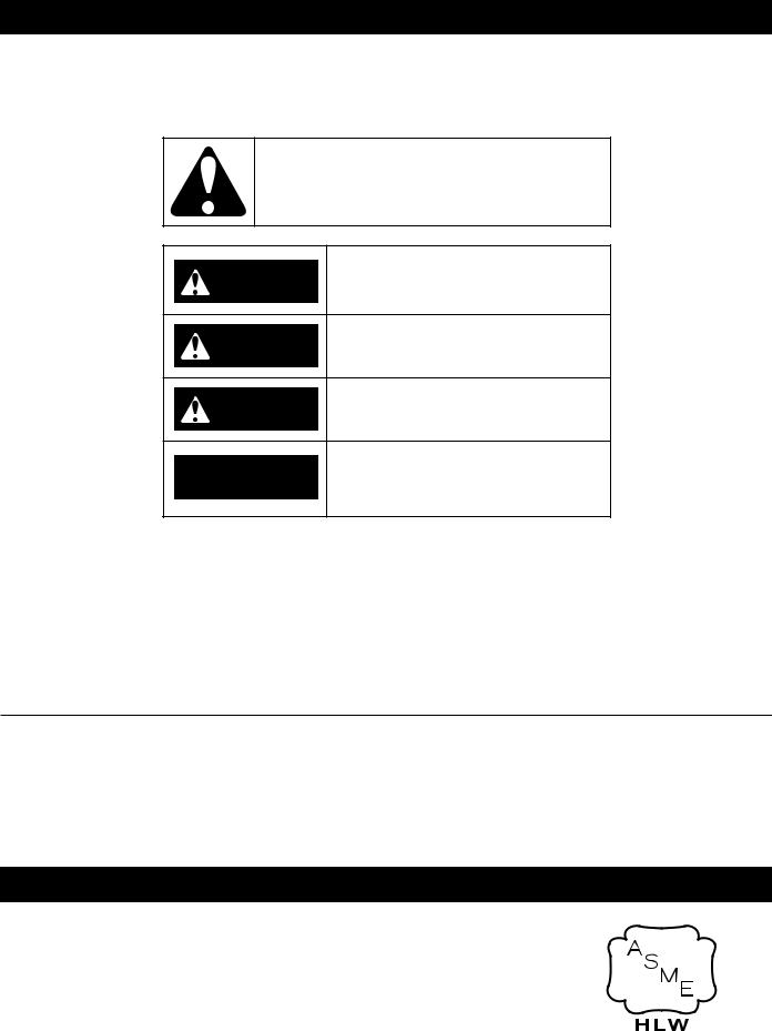
Figure 1. SINGLE HEAT EXCHANGER WATER HEATER |
|
|
|
|
|
|
|
|
|
|
|
|
||||||||||||||||||||||||||||||
|
|
|
|
|
|
|
|
|
|
|
|
|
|
|
|
|
|
|
|
||||||||||||||||||||||||||
|
|
|
|
|
|
|
|
|
|
|
|
|
|
|
|
|
|
|
|
||||||||||||||||||||||||||
|
|
|
Table 1. ROUGH IN DIMENSIONS (SINGLE) |
|
|
|
|
|
|
|
|
|
|
|
|
|
|
|
|
|
|
|
|
|
|||||||||||||||||||||
|
|
|
|
|
|
|
|
|
|
|
|
|
|
|
|
|
|
|
|
|
|
|
|
|
|
|
|
|
|
|
|
|
|
|
|
|
|
|
|
|
|
|
|
|
|
Models |
|
|
|
XB-1000 |
|
|
|
|
|
|
|
|
XB-1300 |
|
|
|
|
|
|
|
|
|
|
|
|
XB-1700 |
|
|
|
|
|
|
|||||||||||||
|
|
|
|
|
|
|
|
|
|
|
|
|
|
|
|
|
|
|
|
|
|
|
|
|
|
|
|
|
|
|
|
|
|
|
|
|
|
|
|
|
|
|
|
|
|
Dimensions |
|
inches |
|
|
|
mm |
|
|
inches |
|
|
mm |
|
|
|
|
|
|
|
|
inches |
|
|
|
|
mm |
|||||||||||||||||||
|
|
|
|
|
|
|
|
|
|
|
|
|
|
|
|
|
|
|
|
|
|
|
|
|
|
|
|
|
|
|
|
|
|
|
|
|
|
|
|
|
|
|
|
|
|
Flue Outlet Diameter |
|
6 |
|
|
|
|
152 |
|
8 |
|
|
|
|
|
|
|
|
152 |
|
|
|
|
8 |
|
|
|
|
|
203 |
|
|
||||||||||||||
|
|
|
|
|
|
|
|
|
|
|
|
|
|
|
|
|
|
|
|
|
|
|
|
|
|
|
|
|
|
|
|
|
|
|
|
|
|
|
|
|
|
|
|
|
|
Air Intake Diameter |
|
6 |
|
|
|
|
152 |
|
6 |
|
|
|
|
|
|
|
|
152 |
|
|
|
|
8 |
|
|
|
|
|
203 |
|
|
||||||||||||||
|
|
|
|
|
|
|
|
|
|
|
|
|
|
|
|
|
|
|
|
|
|
|
|
|
|
|
|
|
|
|
|
|
|
|
|
|
|
|
|
|
|
|
|
|
|
Water Inlet |
|
|
|
|
|
|
|
|
2 inch NPT |
|
|
|
|
|
|
|
|
|
|
|
|
|
|
|
|
|
2 1/2 inch NPT |
||||||||||||||||||
Water Outlet |
|
|
|
|
|
|
|
|
2 inch NPT |
|
|
|
|
|
|
|
|
|
|
|
|
|
|
|
|
|
2 1/2 inch NPT |
||||||||||||||||||
|
|
|
|
|
|
|
|
|
|
|
|
|
|
|
|
|
|
|
|
|
|
|
|
|
|
|
|
|
|
|
|
|
|
|
|
|
|
|
|
|
|
|
|
|
|
Gas Inlet |
|
|
|
|
|
|
|
|
2 inch NPT |
|
|
|
|
|
|
|
|
|
|
|
|
|
|
|
|
|
|
2 inch NPT |
|
|
|
|
|
|
|||||||||||
A |
|
|
47 |
|
|
|
|
1199 |
|
49 |
|
|
|
|
|
|
1245 |
|
|
|
|
57 |
|
|
|
|
|
1448 |
|
||||||||||||||||
B |
|
|
67 |
|
|
|
|
1702 |
|
68 |
|
|
|
|
|
|
1727 |
|
|
|
|
76 |
|
|
|
|
|
1930 |
|
||||||||||||||||
C |
|
|
29 |
|
|
|
|
737 |
|
29 |
|
|
|
|
|
|
737 |
|
|
|
|
29 |
|
|
|
|
|
737 |
|
|
|||||||||||||||
D |
|
|
37 |
|
|
|
|
940 |
|
38 |
|
|
|
|
|
|
965 |
|
|
|
|
37 |
|
|
|
|
|
940 |
|
|
|||||||||||||||
E |
|
|
23 |
|
|
|
|
584 |
|
23 |
|
|
|
|
|
|
584 |
|
|
|
|
24 |
|
|
|
|
|
610 |
|
|
|||||||||||||||
F |
|
|
9 |
|
|
|
|
229 |
|
9 |
|
|
|
|
|
|
|
229 |
|
|
|
|
9 |
|
|
|
|
|
229 |
|
|
||||||||||||||
G |
|
|
34 |
|
|
|
|
864 |
|
34 |
|
|
|
|
|
|
864 |
|
|
|
|
34 |
|
|
|
|
|
864 |
|
|
|||||||||||||||
H |
|
|
44 |
|
|
|
|
1118 |
|
45 |
|
|
|
|
|
|
1143 |
|
|
|
|
45 |
|
|
|
|
|
1143 |
|
||||||||||||||||
J |
|
|
6 |
|
|
|
|
152 |
|
6 |
|
|
|
|
|
|
|
152 |
|
|
|
|
6 |
|
|
|
|
|
152 |
|
|
||||||||||||||
K |
|
|
11 |
|
|
|
|
279 |
|
11 |
|
|
|
|
|
|
279 |
|
|
|
|
11 |
|
|
|
|
|
279 |
|
|
|||||||||||||||
L |
|
|
12 |
|
|
|
|
305 |
|
11 |
|
|
|
|
|
|
279 |
|
|
|
|
12 |
|
|
|
|
|
305 |
|
|
|||||||||||||||
|
|
|
Table 2. OPERATING CHARACTERISTICS |
|
|
|
|
|
|
|
|
|
|
|
|
|
|
|
|
|
|
|
|
|
|||||||||||||||||||||
|
|
|
|
|
|
|
|
|
|
|
|
|
|
|
|
|
|
|
|
|
|
|
|
|
|
|
|
|
|
|
|
|
|
|
|
|
|
|
|
||||||
Models |
|
|
Manifold Pressure |
|
|
|
|
|
|
|
Maximum Supply Pressure |
Minimum Supply Pressure |
|||||||||||||||||||||||||||||||||
(XB) |
Type of Gas |
|
|
Inches W.C. |
|
kPa |
|
|
Inches W.C. |
|
|
kPa |
|
|
|
|
Inches W.C. |
|
|
|
|
kPa |
|||||||||||||||||||||||
|
Natural |
Min Fire |
|
|
-0.2 to - 0.3 |
-0.05 to - 0.07 |
|
|
14.0 |
|
|
|
3.49 |
|
|
|
|
4.0 |
|
|
|
|
1.0 |
|
|||||||||||||||||||||
|
|
|
|
|
|
|
|
|
|
|
|
|
|
|
|
|
|
|
|
|
|
|
|
|
|
|
|||||||||||||||||||
1000, 1300, 1700 |
Max Fire |
|
|
-3.0 to -3.9 |
-0.75 to -0.97 |
|
|
|
|
|
|
|
|
|
|
|
|
||||||||||||||||||||||||||||
|
|
|
|
|
|
|
|
|
|
|
|
|
|
|
|
|
|
|
|
|
|
|
|
|
|
|
|
|
|
|
|
|
|
|
|||||||||||
2000, 2600, 3400 |
|
|
|
|
|
|
|
|
|
|
|
|
|
|
|
|
|
|
|
|
|
|
|
|
|
|
|
|
|
|
|
|
|
|
|
|
|
|
|
|
|
|
|
|
|
Propane |
Min Fire |
|
|
-0.1 to - 0.3 |
-0.025 to -0.07 |
|
|
14.0 |
|
|
|
3.49 |
|
|
|
|
4.0 |
|
|
|
|
1.0 |
|
||||||||||||||||||||||
|
|
|
|
|
|
|
|
|
|
|
|
|
|
|
|
|
|||||||||||||||||||||||||||||
|
|
|
|
|
|
|
|
|
|
|
|
|
|
|
|
|
|
|
|
|
|
|
|
|
|
|
|||||||||||||||||||
|
Max Fire |
|
|
-3.6 to -4.9 |
-0.90 to -1.22 |
|
|
|
|
|
|
|
|
|
|
|
|
||||||||||||||||||||||||||||
|
|
|
|
|
|
|
|
|
|
|
|
|
|
|
|
|
|
|
|
|
|
|
|
|
|
|
|
|
|
|
|
|
|
|
|
||||||||||
|
|
|
|
|
|
|
|
|
|
|
|
|
|
|
|
|
|
|
|
|
|
|
|
|
|
|
|
|
|
|
|
|
|
|
|
|
|
|
|
|
|
|
|
|
|
6
|
|
|
|
|
B |
|
|
|
AIR INTAKE |
|||||||
K |
|
|
|
|
|
J |
|
|
|
|
FLUE OUTLET |
|
G |
|||
|
|
|
|
|
|
|
|
|
|
|
|
|
||||
|
|
|
|
|
|
|
|
|
|
|
|
|
|
|
|
|
|
|
|
|
|
|
|
|
|
|
|
|
|
|
|
|
|
|
|
|
|
|
|
|
|
|
|
|
|
|
|
|
|
|
|
|
|
|
|
|
|
|
|
|
|
|
|
|
|
|
|
34 1/4" |
66 1/8" |
|
|
|
H |
55 7/8" |
E |
31 7/8" |
|
D |
|
7 7/8" |
|
A |
|
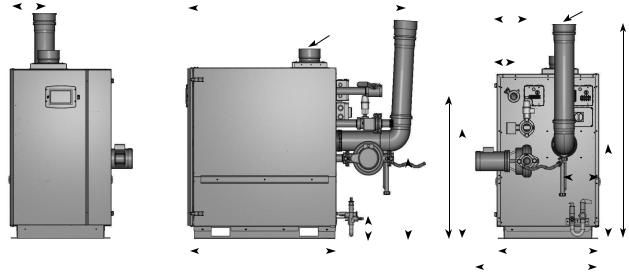
Figure 2. DOUBLE HEAT EXCHANGER WATER HEATER Table 3. ROUGH IN DIMENSIONS (DOUBLE)
86 1/4"
10"
26 3/4"
31 3/8"
C
|
|
Models |
|
|
XB-2000 |
|
|
|
|
|
XB-2600 |
|
|
|
XB-3400 |
|
|||||||
|
|
|
|
|
|
|
|
|
|
|
|
|
|
|
|
|
|
|
|
|
|
|
|
|
Dimensions |
|
|
inches |
|
|
mm |
|
|
|
inches |
|
|
mm |
inches |
|
mm |
||||||
|
|
|
|
|
|
|
|
|
|
|
|
|
|
|
|
|
|
|
|
|
|
|
|
Flue Outlet Diameter |
|
|
8 |
|
203 |
|
|
|
|
8 |
|
|
203 |
|
10 |
|
|
254 |
|||||
|
|
|
|
|
|
|
|
|
|
|
|
|
|
|
|
|
|
|
|
|
|
|
|
Air Intake Diameter |
|
|
8 |
|
203 |
|
|
|
|
8 |
|
|
203 |
|
10 |
|
|
254 |
|||||
|
Water Inlet |
|
|
|
|
|
|
3 inch NPT |
|
|
|
|
|
|
|
4 inch NPT |
|
||||||
|
|
|
|
|
|
|
|
|
|
|
|
|
|
|
|
|
|
|
|
|
|
|
|
Water Outlet |
|
|
|
|
|
|
3 inch NPT |
|
|
|
|
|
|
|
4 inch NPT |
|
|||||||
|
Gas Inlet |
|
|
|
|
|
|
2 inch NPT |
|
|
|
|
|
|
|
3 inch NPT |
|
||||||
|
|
A |
|
|
47 |
|
1194 |
|
|
|
|
49 |
|
|
1245 |
|
57 |
|
|
1448 |
|||
|
|
B |
|
|
78 |
|
1981 |
|
|
|
|
80 |
|
|
2032 |
|
91 |
|
|
2311 |
|||
|
|
C |
|
|
36 |
|
914 |
|
|
|
|
37 |
|
|
940 |
|
37 |
|
|
940 |
|||
|
|
D |
|
|
22 |
|
559 |
|
|
|
|
22 |
|
|
559 |
|
22 |
|
|
559 |
|||
|
|
E |
|
|
40 |
|
1016 |
|
|
|
|
41 |
|
|
1041 |
|
41 |
|
|
1041 |
|||
|
|
F |
|
|
7 |
|
178 |
|
|
|
|
6 |
|
|
152 |
|
6 |
|
|
152 |
|||
|
|
G |
|
|
10 |
|
254 |
|
|
|
|
10 |
|
|
254 |
|
10 |
|
|
254 |
|||
|
|
H |
|
|
4 |
|
102 |
|
|
|
|
4 |
|
|
102 |
|
4 |
|
|
102 |
|||
|
|
J |
|
|
20 |
|
508 |
|
|
|
|
19 |
|
|
483 |
|
19 |
|
|
483 |
|||
|
|
K |
|
|
12 |
|
305 |
|
|
|
|
12 |
|
|
305 |
|
13 |
|
|
330 |
|||
|
|
|
|
|
|
|
Table 4. RECOVERY CAPACITIES |
|
|
|
|
|
|
||||||||||
|
|
|
|
|
|
|
|
|
|
|
|
|
|
|
|
|
|
|
|
||||
Models |
|
Input |
|
Water |
|
|
|
|
|
|
|
Temperature Rise - ΔT °F (°C) |
|
|
|
||||||||
|
|
|
|
|
|
|
|
|
|
|
|
|
|
|
|
|
|
|
|
||||
|
Rating |
|
40 |
|
|
60 |
|
70 |
|
80 |
|
|
90 |
|
100 |
120 |
140 |
||||||
(XWH) |
|
|
Flow |
|
|
|
|
|
|
|
|||||||||||||
|
(Btu/hr) |
|
|
|
|
|
|
|
|||||||||||||||
|
|
|
|
|
(22) |
|
(33) |
|
(39) |
|
(44) |
|
(50) |
|
(56) |
(67) |
(78) |
||||||
|
|
|
|
|
|
|
|
|
|
|
|
|
|
|
|
|
|
||||||
1000 |
|
920,000 |
|
GPH |
2,662 |
|
|
1,775 |
|
1,521 |
|
1,331 |
|
1,183 |
|
1,065 |
887 |
761 |
|||||
|
|
LPH |
10,078 |
|
|
6,719 |
|
5,759 |
|
5,039 |
|
4,479 |
|
4,031 |
3,359 |
2,880 |
|||||||
|
|
|
|
|
|
|
|
|
|||||||||||||||
1300 |
|
1,300,000 |
|
GPH |
3,742 |
|
|
2,495 |
|
2,139 |
|
1,871 |
|
1,663 |
|
1,497 |
1,247 |
1,069 |
|||||
|
|
LPH |
14,167 |
|
|
9,444 |
|
8,095 |
|
7,083 |
|
6,296 |
|
5,667 |
4,722 |
4,048 |
|||||||
|
|
|
|
|
|
|
|
|
|||||||||||||||
1700 |
|
1,700,000 |
|
GPH |
4,904 |
|
|
3,269 |
|
2,802 |
|
2,452 |
|
2,180 |
|
1,962 |
1,635 |
1,401 |
|||||
|
|
LPH |
18,565 |
|
|
12,376 |
|
10,608 |
|
9,282 |
|
8,251 |
|
7,426 |
6,188 |
5,304 |
|||||||
|
|
|
|
|
|
|
|
|
|||||||||||||||
2000 |
|
1,999,900 |
|
GPH |
5,794 |
|
|
3,862 |
|
3,311 |
|
2,897 |
|
2,575 |
|
2,317 |
1,931 |
1,655 |
|||||
|
|
LPH |
21,931 |
|
|
14,621 |
|
12,532 |
|
10,966 |
|
9,747 |
|
8,773 |
7,310 |
6,266 |
|||||||
|
|
|
|
|
|
|
|
|
|||||||||||||||
2600 |
|
2,600,000 |
|
GPH |
7,501 |
|
|
5,000 |
|
4,286 |
|
3,750 |
|
3,334 |
|
3,000 |
2,500 |
2,143 |
|||||
|
|
LPH |
28,393 |
|
|
18,929 |
|
16,225 |
|
14,196 |
|
12,619 |
|
11,357 |
9,464 |
8,112 |
|||||||
|
|
|
|
|
|
|
|
|
|||||||||||||||
3400 |
|
3,400,000 |
|
GPH |
9,891 |
|
|
6,594 |
|
5,652 |
|
4,945 |
|
4,396 |
|
3,956 |
3,297 |
2,826 |
|||||
|
|
LPH |
37,441 |
|
|
24,961 |
|
21,395 |
|
18,721 |
|
16,641 |
|
14,976 |
12,480 |
10,697 |
|||||||
|
|
|
|
|
|
|
|
|
|||||||||||||||
7

ELECTRICAL REQUIREMENTS
Table 5. ELECTRICAL REQUIREMENTS
MODELS |
SUPPLY VOLTAGE |
FREQUENCY |
CURRENT |
ELECTRICAL NOTES |
|
(XWH) |
(VOLTS) |
(HZ) |
(AMPS) |
|
|
1000 |
120 |
60 |
30 |
A dedicated, single phase, 30 amp circuit breaker with |
|
1300 |
120 |
60 |
30 |
a grounded neutral should be provided to supply power |
|
to the water heater. |
|||||
|
|
|
|
||
1700 |
120 |
60 |
30 |
||
|
|||||
2000 |
120 |
60 |
60 |
A dedicated, single phase, 60 amp circuit breaker with |
|
|
|
|
|
a grounded neutral should be provided to supply power |
|
2600 |
120 |
60 |
60 |
||
to the water heater. |
|||||
3400 |
120 |
60 |
60 |
||
|
8

FLOW, HEAD AND TEMPERATURE RISE
Table 6. FLOW, HEAD AND TEMPERATURE RISE
Models |
Input |
|
|
Temperature Rise - ΔT °F |
|
Flow Rate |
|||
Water Flow |
|
|
|
|
|
|
|
||
|
|
|
|
|
|
|
|||
(XWH) |
(Btu/hr) |
20 |
|
30 |
|
40 |
Maximum |
Minimum |
|
|
|
|
|||||||
|
|
|
|
|
|||||
|
|
|
|
|
|
|
|
|
|
|
|
GPM |
86 |
|
56 |
|
43 |
86 |
43 |
1000 |
920,000 |
LPM |
325 |
|
211 |
|
162 |
325 |
162 |
ΔP FT |
26 |
|
12 |
|
7 |
26 |
7 |
||
|
|
|
|
||||||
|
|
ΔP M |
7.9 |
|
3.7 |
|
2.1 |
7.9 |
2.1 |
|
|
GPM |
120 |
|
80 |
|
60 |
120 |
60 |
1300 |
1,300,000 |
LPM |
453 |
|
302 |
|
226 |
453 |
226 |
ΔP FT |
32.5 |
|
15 |
|
8 |
32.5 |
8 |
||
|
|
|
|
||||||
|
|
ΔP M |
9.9 |
|
4.6 |
|
2.4 |
9.9 |
2.4 |
|
|
GPM |
156 |
|
104 |
|
78 |
156 |
78 |
1700 |
1,700,000 |
LPM |
592 |
|
395 |
|
296 |
592 |
296 |
ΔP FT |
35 |
|
14 |
|
8 |
35 |
8 |
||
|
|
|
|
||||||
|
|
ΔP M |
10.7 |
|
4.3 |
|
2.4 |
10.7 |
2.4 |
|
|
GPM |
184 |
|
123 |
|
92 |
184 |
92 |
2000 |
1,999,900 |
LPM |
696 |
|
464 |
|
348 |
696 |
348 |
ΔP FT |
26 |
|
12 |
|
7 |
26 |
7 |
||
|
|
|
|
||||||
|
|
ΔP M |
7.9 |
|
3.7 |
|
2.1 |
7.9 |
2.1 |
|
|
GPM |
239 |
|
159 |
|
120 |
239 |
120 |
2600 |
2,600,000 |
LPM |
905 |
|
604 |
|
453 |
905 |
453 |
ΔP FT |
32.5 |
|
15 |
|
8 |
32.5 |
8 |
||
|
|
|
|
||||||
|
|
ΔP M |
9.9 |
|
4.6 |
|
2.4 |
9.9 |
2.4 |
|
|
GPM |
313 |
|
209 |
|
156 |
313 |
156 |
3400 |
3,400,000 |
LPM |
1184 |
|
789 |
|
592 |
1184 |
592 |
ΔP FT |
35 |
|
14 |
|
8 |
35 |
8 |
||
|
|
|
|
||||||
|
|
ΔP M |
10.7 |
|
4.3 |
|
2.4 |
10.7 |
2.4 |
NOTE: Head Loss shown is through the water heater only and allows for no additional piping.
9
FEATURES AND COMPONENTS
|
2 |
|
|
25 |
|
35 |
24 |
|
10 |
27 |
36 |
|
|
29
 34
34
17
33 8
1
|
|
31 |
|
|
23 |
28 |
32 |
5 |
|
|
9
26
26 
6
3
4
16
20
18
13
19
 7
7
12
21
11
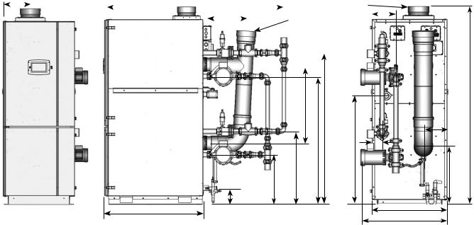
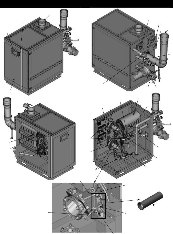
Figure 3. SINGLE HEAT EXCHANGER WATER HEATER COMPONENTS
10

10
35
1
26
3
2
25
24
27
36
 29
29  34
34
17
33
31 |
8 |
|
|
|
5 |
32
23
18
26 
28
9 |
|
4 |
6 |
|
20
18
13 |
19 |
16 |
 7
7
21
 11
11
12
Figure 4. DOUBLE HEAT EXCHANGER WATER HEATER COMPONENTS
11

COMPONENT DESCRIPTION
1. Front access door:
Provides access to the gas train, burner controllers and the heat exchanger.
2. Air Filter Box:
Allows for the connection of the PVC air intake pipe to the water heater through a standard PVC adapter. It uses a filter mounted inside the box to prevent dust and debris from entering the water heater.
3. Automatic air vents:
Designed to remove trapped air from the heat exchanger coils.
4. Blowers:
The blowers pull in air and gas through the venturis. Air and gas mix inside the venturi and are pushed into the burners, where they burn inside the combustion chamber.
5. Inlet temperature sensors
These sensors monitor system return water temperature.
6. Outlet temperature sensors/High Limits
These sensors monitor water heater outlet water temperature. The water heater modulates based on the Lead Lag Sensor connected to the tank.
7. Burners
Made with metal fiber and stainless steel construction, the burners use pre-mixed air and gas and provide a wide range of firing rates.
8. Condensate Trap
Disposes the condensate produced from heat exchanger and houses a switch that detects in case of blockage.
9. Control modules
The control modules respond to internal and external signals and control the blowers, gas valves, and pumps to meet the heating demand.
10. Touch Screen Display
Digital controls with touch screen technology and full color display.
11. Sight glass
The quartz sight glass provides a view of the flame for inspection purposes.
12. Flame sensors
Used by the control module to detect the presence of burner flame.
13. Flap valves
Prevents recirculation of flue products when only one burner is running.
14. Flue gas sensors (not visible)
These sensors monitor the flue gas exit temperature. The control modules will modulate and shut down the water heater if the flue gas temperature gets too hot. This protects the flue pipe from overheating.
15. Flue pipe adapter (not visible)
Allows for the connection of the PVC vent pipe system to the water heater.
16. Gas shutoff valves (Internal unit)
Manual valves used to isolate the gas valves from the burners.
17. Main gas shutoff valve (External unit)
Manual valve used to isolate the water heater from the gas supply.
18. Automatic modulating gas valve
The gas valve with the addition of venturi and blower are used for modulating premix appliances.
19. Heat exchanger access covers
Allows access to the combustion side of the heat exchanger coils.
20. High gas pressure switch
Switch provided to detect excessive supply gas pressure.
21. Spark Igniter
Provides direct spark for igniting the burners.
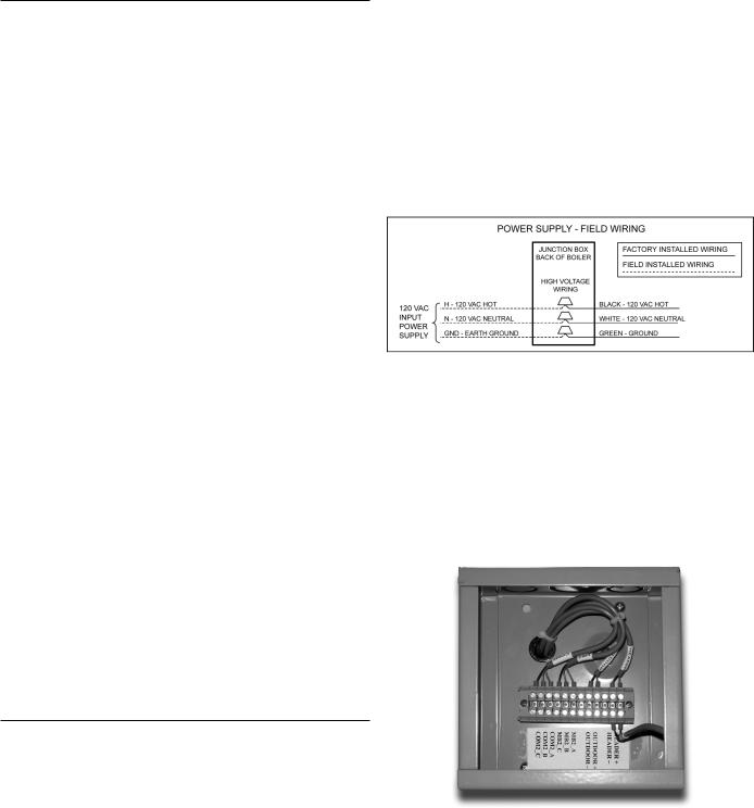
22. Power supply terminals (not visible)
The main power to the water heater is supplied through the terminals housed inside the high voltage junction box.
23. Low gas pressure switch
Switch provided to detect low gas supply pressure.
24. High voltage connection box
This box has terminals for connecting the main power supply (120V) to the water heater and outputs power supply (120V) for the pumps from the water heater control. This box has terminals for low voltage devices such as condensate trap and flow switch.
25. Sensors/Communication Box
Connects sensors to tank sensor/header sensor and external connections to building managements systems through MODBUS.
26. Low water cutoff board and sensor probe (LWCO)
Device used to ensure adequate water is supplied to the water heater. In the event of inadequate water levels, LWCO will ensure water heater shut down. LWCO board is connected to the electronic panel, whereas the sensor probe is connected to the heat exchanger.
27. Main power supply switch
Turns 120 VAC ON/OFF to the water heater.
28. Pump relay
The pump relays are used for providing power to the water heater.
29. Pressure relief valve
Protects the heat exchangers from an over pressure condition. ThereliefvalvewillbesetatparticularPSI,dependingonmodels.
30.Reset switch (optional) (not visible) Reset switch for the low water cutoff.
31.Stainless steel heat exchangers
Allows system water to flow through specially designed coils.
32. Venturi
The venturi is a gas/air mixing unit that allows modulation of a premix burner with constant gas/air ratio.
33. Water inlet
Water connection that return water from the system to the heat exchangers.
34. Water outlets
A NPT water connection that supplies hot water to the system.
35. Enable/Disable Switch
This is an emergency water heater turn off switch which disconnects the interlock voltage to the control board, hence turning off the power supply to the gas valves. Do not use this switch for turning off the water heater, this should be done from the touch screen display, using the Operational Switch on the Lead Lag screen.
36. Vent outlet
Provides an outlet for combustion gases to outdoor.
12
CONTROL COMPONENTS
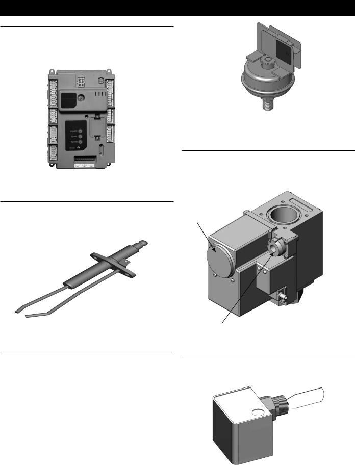
THE CONTROL SYSTEM
The R7910A1138 is a burner control system that provides heat control, flame supervision, circulation pump control, fan control, water heater control sequencing, and electric ignition function. It will also provide status and error reporting.
Figure 5. BURNER CONTROL SYSTEM
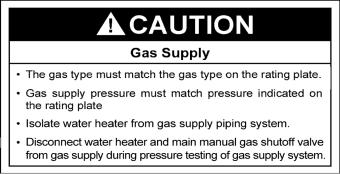
SPARK IGNITER
The spark igniter is a device that ignites the main burner. When power is supplied to the igniter electrode, an electric arc is created between the electrode and the ground terminal which ignites the main burner.
Figure 6. SPARK IGNITER
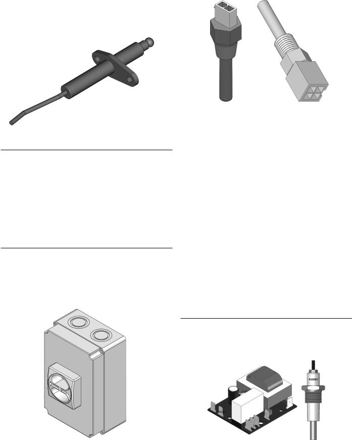
LOW/HIGH GAS PRESSURE SWITCH
This XWH is equipped with a low gas pressure switch which meets the CSD-1 code requirements.
The Low Gas Pressure Switch is normally open and remains open if the pressure is below the preset pressure. It closes as soon as the gas supply pressure is above the minimum supply pressure.
The High Gas Pressure Switch is normally closed and is used to detect excessive gas pressure.
Figure 7. LOW/HIGH GAS PRESSURE SWITCH
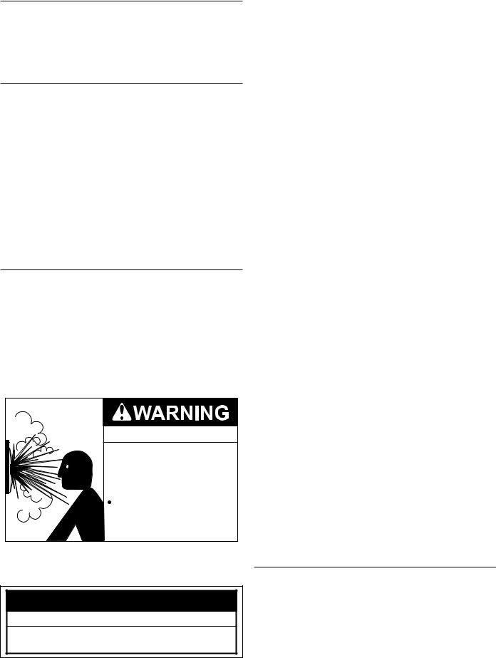
GAS CONTROL VALVE
The gas valve is a normally closed servo regulated gas valve. The valve opens only when energized by the burner control and closes when the power is removed. The burner control supplies 24 volts to the gas valve during operation.
H I G H F I R I N G
RATE SETTING
L O W F I R I N G
RATE SETTING
Figure 8. GAS CONTROL VALVE
WATER FLOW SWITCH
The water flow switch activates when sufficient water flow has been established. Switch will not close when water flow is not present.
Figure 9. WATER FLOW SWITCH
13
FLAME SENSOR |
|
WATER TEMPERATURE SENSORS |
Each burner is equipped with a flame sensor to detect the presence of the burner flames at high and low fire conditions. If no flame is sensed, the gas valve will close automatically. The voltage sensed by the flame sensor will also be displayed on the Burner Screen.
Figure 10. FLAME SENSOR
WATER TEMPERATURE LIMIT CONTROLS
This water heater incorporates an outlet water sensor having dual sensors, that are factory set at 210°F (99°C).
MAIN POWER SUPPLY SWITCH
The main power supply switch is a padlockable switch. This switch provides 120V from the power supply to the water heater.
This switch needs to be turned off when servicing the water heater.
NOTE: The Enable/Disable (Interlock) Switch on the front of the water heater does not interrupt electrical power to the water heater.
Figure 11. MAIN POWER SUPPLY SWITCH
Figure 12. WATER TEMPERATURE SENSORS
Temperature sensors are threaded immersion probes. Temperature probes have embedded temperature sensors (thermistors). The water heater’s control system monitors these sensors to determine water temperature at various points in the system.
INLET AND OUTLET TEMPERATURE SENSORS
All models have two inlet and two outlet temperature sensors for each heat exchanger, factory installed to monitor the water temperature entering and leaving the water heater. The Inlet Probe is a temperature sensor only and has two leads. The Outlet probe also contains the manual reset high temperature limit switch and has four leads. The control system displays the Inlet and Outlet water temperatures sensed from these two sensors on the default Temperatures screen.
REMOTE SENSORS
All models are supplied from the factory with a remote sensor. The remote sensor is used to control system water temperature for a single water heater in a domestic hot water storage tank.
The water heater will modulate its firing rate in response to the actual system temperature and load conditions. The control system displays the temperature sensed from the remote sensor as the “Lead Lag” temperature on the default Temperatures screen.
LOW WATER CUTOFF DEVICE (LWCO)
Low water cutoff device is normally a closed switch that opens when water drops below a preset level. Each model is equipped with a factory installed LWCO. LWCO board is connected to the electronic panel, whereas the sensor probe is connected to the heat exchanger.
Figure 13. LWCO BOARD AND PROBE
14

INSTALLATION CONSIDERATIONS
GENERAL
If the system is to be filled with water for testing or other purposes during cold weather and before actual operation, care must be taken to prevent freezing of water in the system. Failure to do so may cause thewaterinthesystemtofreezewithresultingdamagetothesystem.
Damage due to freezing is not covered by the warranty.
Figure 76 on Page 79 shows a typical primary, secondary piping method. This is the preferred piping method for most circulating water heaters. Other piping methods, however, may provide good system operation. A prime concern when designing heating systems is the maintenance of proper flow through the unit during water heater operation. The secondary pump should be sized per the recommended flow rate of the water heater, see Dimension and Capacity Data section in this manual.
Before locating the water heater:
1.Check for nearby connection to:
•System water piping
•Venting connections
•Gas supply piping
•Electrical power
2.Locate the water heater so that if water connections should leak, water damage will not occur. When such locations cannot be avoided, it is recommended that a suitable drain pan, adequately drained, be installed under the appliance. The pan must not restrict combustion air flow. Under no circumstances is the manufacturer to be held responsible for water damage in connection with this appliance, or any of its components.
3.Check area around the water heater. Remove any combustible materials, gasoline and other flammable liquids.
4.Make sure the gas control system components are protected from dripping or spraying water or rain during operation or service.
5.If a new water heater will replace an existing water heater, check for and correct system problems, such as:
•System leaks causing oxygen corrosion or heat exchanger cracks from hard water deposits.
•Lack of freeze protection in water heater water causing system and water heater to freeze and leak.
CIRCULATING PUMP
A circulating pump is used when a system requires a circulating loop or there is a storage tank used in conjunction with the water heater. Install in accordance with the current edition of the National Electrical Code, NFPA 70 or the Canadian Electrical Code, CSA C22.1. All bronze circulating pumps are recommended for use with commercial water heaters. Some circulating pumps are manufactured with sealed bearings and do not require further lubrication. Some circulating pumps must be periodically oiled. Refer to the pump manufacturer’s instructions for lubrication requirements.
XWH Models: The circulating pump is integral to the XWH models. This pump has been lubricated at the factory, and future lubricationshouldbeinaccordancewiththemotormanufacturer’s instructions provided as a supplement to this manual.
PRIMARY SYSTEM CONTROL
All XWH installations require a “Primary System Control” that senses and reacts to water temperature inside the storage tank on domestic water applications. The Primary System Control will activate and deactivate water heater heating cycles based on its setpoint and current system water temperature. There are three suitable methods to configure a Primary System Control. One of these three methods must be used.
1.The Primary System Control can be the water heater’s control system working with the factory supplied Header Sensor, installed inside the storage tank on domestic water applications.
2.Alternatively, the Burner Control system can be used as a Primary System Control. It will also provide water heater status and error reporting. Multiple water heaters can be joined together to heat a system instead of a single, larger burner or water heater. Using water heaters in parallel is more efficient, costs less, reduces emissions, improves load control, and is more flexible than the traditional large water heater.
3.MB2 and COM2 ports can be used for Building Management Systems.
INTERNAL CONTAMINANTS
The system must be internally cleaned and flushed after a new or replacement water heater has been installed, to remove contaminants that may have accumulated during installation. This is extremely important when a replacement water heater is installed into an existing system where Stop Leak or other water heater additives have been used.
Failure to clean and flush the system can produce acid concentrations that become corrosive, and leads to heat exchanger failure.
All hot water heating systems should be completely flushed with a grease removing solution to assure trouble-free operation. Pipe joint compounds, soldering paste, grease on tubing and pipe all tend to contaminate a system
Failure to flush contaminants from a system can cause solids to form on the inside of heat exchangers, create excessive blockage of water circulation, deterioration of the pump seals and impellers.
WATER LINE CONNECTIONS
Piping diagrams will serve to provide the installer with a reference for the materials and methods of piping necessary for installation. It is essential that all water piping be installed and connected as shown on the diagrams. Check the diagrams to be used thoroughly before starting installation to avoid possible errors and to minimize time and material cost. It is essential that all water piping be installed and connected as shown on the diagrams. See Figure 76 on Page 79 and Figure 77 on Page 80.
15
CLOSED WATER SYSTEMS
Water supply systems may, because of code requirements or such conditions as high line pressure, among others, have installed devices such as pressure reducing valves, check valves, and back flow preventers. Devices such as these cause the water system to be a closed system.
THERMAL EXPANSION
As water is heated, it expands (thermal expansion). In a closed system the volume of water will increase when it is heated.As the volume of water increases there will be a corresponding increase in water pressure due to thermal expansion. Thermal expansion can cause premature failure (leakage). This type of failure is not covered under the limited warranty. Thermal expansion can also cause intermittent Temperature-Pressure Relief Valve operation: water discharged from the valve due to excessive pressure build up. This condition is not covered under the limited warranty. The Temperature-Pressure Relief Valve is not intended for the constant relief of thermal expansion.
A properly sized thermal expansion tank must be installed on all closed systems to control the harmful effects of thermal expansion. Contact a local plumbing service agency to have a thermal expansion tank installed.
PRESSURE RELIEF VALVE
An ASME rated pressure relief valve is furnished with the water heater. A fitting for the relief valve is provided in the top of the water heater. Never operate the heating elements without being certain the water heater is filled with water and a properly sized pressure relief valve is installed in the relief valve opening provided.
The pressure rating of the relief valve should be equal to or less than the rated pressure capacity of any component in the system including the water heater. Should the valve need to be replaced, call the toll free phone number listed on the back of this manual for further technical assistance
Explosion Hazard
 Relief Valve must comply with ASME code.
 Properly sized Relief Valve must be installed in opening provided.
Can result in overheating and excessive tank pressure.
 Can cause serious injury or death.
A discharge pipe from the relief valve should terminate at an adequate floor drain. Do not thread, plug, or cap the end of drain line.
CAUTION
Water Damage Hazard
•Pressure Relief Valve discharge pipe must terminate at adequate drain.
The Discharge Pipe:
•Shall not be smaller in size than the outlet pipe size of the valve, or have any reducing couplings or other restrictions.
•Shall not be plugged or blocked.
•Shall not be exposed to freezing temperatures.
•Shall be of material listed for hot water distribution.
•Shall be installed so as to allow complete drainage of both the relief valve and the discharge pipe.
•Must terminate a maximum of six inches above a floor drain or external to the building. In cold climates, it is recommended that the discharge pipe be terminated at an adequate drain inside the building.
•Shall not have any valve or other obstruction between the relief valve and the drain.
Once the water heater is installed and filled with water and the system is pressurized, manually test the operation of the pressure relief valve. See the Maintenance Procedures section of this manual for instructions.
Your local code authority may have other specific safety relief valve requirements not covered below. If any pressure relief valve is replaced, the replacement valve must comply with the requirements for Relief Valves for Hot Water Supply Systems, ANSI Z21.22 • CSA 4.4, and the code requirements of ASME.
XWH water heaters are shipped with a 125 psi (860 kPa) pressure relief valve that must be installed in the water outlet as near to the water heater as possible.
This ASME-rated valve has a discharge capacity that exceeds maximum water heater input rating and a pressure rating that does not exceed maximum working pressure shown on water heater rating plate.
In addition, a CSA design-certified and ASME-rated temperature and pressure (T&P) relief valve must be installed on each and every water storage tank in hot water supply system. The T&P relief valve must comply with applicable construction provisions of StandardforReliefValvesforHotWaterSupplySystems,ANSI Z21.22 or CSA 4.4. T&P relief valve must be of automatic reset type and not embody a single-use type fusible plug, cartridge or linkage.
T&P relief valve should have a temperature rating of 210°F (99°C), a pressure rating not exceeding lowest rated working pressure of any system component, and a discharge capacity exceeding total input of water heaters supplying water to storage tank.
Locate the T&P relief valve (a) in the top of the tank, or (b) in the side of the tank on a centerline within the upper 6 inches (152 mm) of the top of the tank, see Figure 76 and Figure 77. The tapping should be threaded in accordance with the current edition of the Standard for Pipe Threads, General Purpose (inch),ANSI/ASME B1.20.1. The location of, or intended location for, the T&P relief valve should be readily accessible for servicing or replacement.
GAS CONNECTIONS
Make sure the gas on which water heater is to operate is same as that specified on the rating plate. Do not install water heater if equipped for a different type of gas. Consult your gas supplier.
This water heater is not intended to operate at gas supply pressure other than shown on the rating plate. A lock-up or positive shut-off type regulator must be installed in gas supply line. For proper gas regulation the lock-up style regulators must be installed no closer than a minimum of 3 feet (0.9 m) from the water heater and a maximum of 8 feet (2.4 m) away from the
16
water heater. Exposure to higher gas supply pressure may cause damage to gas valves which can result in fire or explosion. If overpressure has occurred such as through improper testing of gas lines or emergency malfunction of supply system, the gas valves must be checked for safe operation. Make sure that the outside vents on supply regulators and the safety vent valves are protected against blockage. These are parts of the gas supply system, not water heater. Vent blockage may occur during ice build-up or snowstorms.
The water heater must be isolated from the gas supply piping system by closing its main manual gas shut off valve during any pressure testing of the gas supply piping system at test pressures equal to or less than 1/2 psig.
Disconnect the water heater and its main manual gas shut-off valve from the gas supply piping during any pressure testing of the gas supply system over 1/2 psig. The gas supply line must be capped when not connected to the water heater.
It is important to guard against gas valve fouling from contaminants in the gas ways. Such fouling may cause improper operation, fire or explosion. If copper supply lines are used they must be approved for gas service.
When local codes require a main manual shut-off valve outside the water heater jacket, a suitable main manual shut-off valve must be installed in a location complying with those codes.
Before attaching gas line be sure that all gas pipe is clean on inside. To trap any dirt or foreign material in the gas supply line, a sediment trap must be incorporated in piping. The sediment trap must be readily accessible and not subject to freezing conditions. Install in accordance with recommendations of serving gas supplier. Refer to the current edition of the National Fuel Gas Code, ANSI Z223.1/NFPA 54 or the Natural Gas and Propane Installation Code, CAN/CSA B149.1
Size of gas supply piping may be larger than heater connection on installations where a significant run of piping is required.
To prevent damage, care must be taken not to apply too much torque when attaching gas supply pipe to water heater gas inlet. When installing and tightening gas piping use a second wrench to hold the gas valve to keep the valve from turning. To prevent damage to the gas valve do not use pipe wrench on the valve body.
Fittings and unions in gas line must be of metal to metal type. Apply joint compounds (pipe dope) sparingly and only to the male threads of pipe joints. Do not apply compound to the first two threads. Use compounds resistant to the action of liquefied petroleum gases. The water heater and its gas connection must be leak tested before placing the water heater in operation.
GAS SUPPLY LINE SIZING
The gas piping installation must be capable of supplying the maximumprobablegasdemandwithoutexcessivepressureloss. Depending on local practices, the ALLOWABLE PRESSURE LOSS between the gas meter, or service regulator and each
appliance is generally 0.3 or 0.5 inches of water column (0.075 or 0.124 kPa).
For single water heater installation, refer to Table 7 and Table 8 to size iron pipe or equivalent gas supply line size to be used with single unit.
For multiple water heater installation or installations of a single water heater with other gas appliances, please refer to Table 9 and Table 10 on Page 19 to size iron pipe or equivalent gas supply line. These tables are taken from the current edition of the National Fuel Gas Code, ANSI Z223.1/NFPA 54 or the Natural Gas and Propane Installation Code, CAN/CSA B149.1.
•Table 9 is based on a pressure drop of 0.5 inches water column (0.124 kPa), and a gas with a specific gravity of
0.60and a heating value of 1,000 BTU/ft3, approximately that of Natural Gas.
•Table 10 is based on a pressure drop of 0.5 inches water column (0.124 kPa), and a gas with a specific gravity of
1.53and a heating value of 2,500 BTU/ft3, approximately that of Propane Gas.
Where it is necessary to use more than the average number of fittings (i.e., elbows, tees and valves in gas supply line) use a pipe larger than specified to compensate for increased pressure drop.
Table 7 and Table 8 shows the maximum equivalent gas pipe length for a single unit installation. It does not take into account other appliances that may be connected to the gas line. For installation of multiple units, or instances where several appliances are connected to the same line, use Table 9 and Table 10 for proper sizing.
Table 7.
SINGLE UNIT INSTALLATION, SUGGESTED GAS PIPE SIZING. MAXIMUM EQUIVALENT PIPE LENGTH (IN FEET).
BTU |
2” |
|
2-1/2” |
3” |
|
|
4” |
||||
Input |
Nat |
|
Pro |
Nat |
Pro |
Nat |
|
Pro |
Nat |
|
Pro |
920,000 |
70 |
|
150 |
175 |
----- |
----- |
|
----- |
----- |
|
----- |
1,300,000 |
40 |
|
100 |
100 |
200 |
----- |
|
----- |
----- |
|
----- |
|
|
|
|
|
|
|
|
|
|
|
|
1,700,000 |
20 |
|
60 |
70 |
150 |
200 |
|
----- |
----- |
|
----- |
|
|
|
|
|
|
|
|
|
|
|
|
2,000,000 |
20 |
|
50 |
50 |
100 |
150 |
|
----- |
----- |
|
----- |
|
|
|
|
|
|
|
|
|
|
|
|
2,600,000 |
10 |
|
30 |
30 |
70 |
90 |
|
200 |
----- |
|
----- |
|
|
|
|
|
|
|
|
|
|
|
|
3,400,000 |
----- |
|
----- |
20 |
40 |
50 |
|
125 |
200 |
|
----- |
|
|
|
|
|
|
|
|
|
|
|
|
Natural gas 1000 Btu/ft^3, 0.60 specific gravity @ 0.3 in. w.c. pressure drop. Propane gas 2500 Btu/ft^3, 1.50 specific gravity @ 0.3 in. w.c. pressure drop.
Table 8.
SINGLE UNIT INSTALLATION, SUGGESTED GAS PIPE SIZING. MAXIMUM EQUIVALENT PIPE LENGTH (IN FEET).
BTU |
2” |
|
2-1/2” |
3” |
|
|
4” |
||||
Input |
Nat |
|
Pro |
Nat |
Pro |
Nat |
|
Pro |
Nat |
|
Pro |
|
|
|
|
|
|
|
|
|
|
|
|
920,000 |
125 |
|
200 |
200 |
----- |
----- |
|
----- |
----- |
|
----- |
1,300,000 |
80 |
|
175 |
175 |
----- |
----- |
|
----- |
----- |
|
----- |
|
|
|
|
|
|
|
|
|
|
|
|
1,700,000 |
40 |
|
100 |
100 |
----- |
----- |
|
----- |
----- |
|
----- |
|
|
|
|
|
|
|
|
|
|
|
|
2,000,000 |
30 |
|
80 |
80 |
200 |
200 |
|
----- |
----- |
|
----- |
|
|
|
|
|
|
|
|
|
|
|
|
2,600,000 |
20 |
|
50 |
50 |
125 |
150 |
|
----- |
----- |
|
----- |
|
|
|
|
|
|
|
|
|
|
|
|
3,400,000 |
10 |
|
30 |
30 |
70 |
90 |
|
200 |
----- |
|
----- |
|
|
|
|
|
|
|
|
|
|
|
|
Natural gas 1000 Btu/ft^3, 0.63 specific gravity @ 0.5 in. w.c. pressure drop. Propane gas 2500 Btu/ft^3, 1.50 specific gravity @ 0.5 in. w.c. pressure drop.
17
CORROSIVE MATERIALS AND CONTAMINATION SOURCES
Products to avoid:
•Spray cans containing chloro/fluorocarbons
•Permanent wave solutions
•Chlorinated waxes/cleaners
•Chlorine-based swimming pool chemicals
•Calcium chloride used for thawing
•Sodium chloride used for water softening
•Refrigerant leaks
•Paint or varnish removers
•Hydrochloric acid/muriatic acid
•Cements and glues
•Antistatic fabric softeners used in clothes dryers
•Chlorine-type bleaches, detergents, and cleaning solvents found in household laundry rooms
•Adhesives used to fasten building products and other similar products
Areas likely to have contaminants:
•Dry cleaning/laundry areas and establishments
•Swimming pools
•Metal fabrication plants
•Beauty shops
•Refrigeration repair shops
•Photo processing plants
•Auto body shops
•Plastic manufacturing plants
•Furniture refinishing areas and establishments
•New building construction
•Remodeling areas
Common household products, pool and laundry products may contain fluorine or chlorine compounds. When these chemicals come in contact with the water heater, they react and can form strong acids. The acid can spoil the water heater wall, causing serious damage and may result in flue gas spillage or water heater water leakage into the building.
If the above mentioned contaminants and corrosive materials chemicals are present near the location of the water heater, make sure to remove the water heater permanently or relocate air inlet and vent terminations to other areas.
FIELD WIRING
120 VAC POWER SUPPLY WIRING
A dedicated, single phase, 30-60 amp (refer to Table 5 on Page 8) circuit breaker with a grounded neutral should be provided to supply power to the water heaters. Use #10 AWG wire for the 120 VAC power supply to the water heater. All 120 VAC power supply connections must be made as shown in Figure 14. These connections should be made at the rear of the unit where a wiring junction box is provided. Field installed power supply wiring to the water heater should be installed in conduit. This conduit and wiring should be separate from any other conduit/wiring to guard against EMI (electromagnetic interference).
POWER SUPPLY CHECK
To reduce the possibility of electrical interference with the water heater’s control system the power supply voltage, polarity and ground must be checked. Using an AC volt meter check the 120 VAC power supply wiring from the breaker prior to making power supply connections at the water heater. Confirm the power supply voltage & polarity are correct and that an adequate ground connection is present by performing the three voltage tests below. See Figure 14 for wiring references.
Confirm RMS voltage between:
•H and GND = 108 VAC minimum, 132 VAC maximum.
•N and H = 108 VAC minimum, 132 VAC maximum.
•N and GND = < 1 VAC maximum.
Figure 14. FIELD WIRING
LOW VOLTAGE CONTROL WIRING
1.Header Terminals: In XWH water heaters the header terminals are connected to the tank sensor where the temperature can be sensed. See Figure 15. The tank sensor is to be connected using the factory supplied sensor harness. The maximum length of the wire connecting from the water heater to the outdoor sensor must be no more than 50 feet (15.2 m).
2.MB2 and COM2 terminals are meant for building management systems.
Figure 15. LOW VOLTAGE CONTROL WIRING
All low voltage control wiring connections must be made as shown in Figure 14. These connections should be made at the rear of the unit where a wiring junction box is provided. Field installed wiring inside 1/2 inch conduit is installed between the junction box on the back of the water heater and the temperature probe and/or field supplied external control being used. This conduit and wiring should be separate from any other conduit/ wiring to guard against EMI (electromagnetic interference).
18

Table 9. SUGGESTED PIPE SIZE FOR MULTIPLE GAS APPLIANCES (NATURAL GAS)
Nominal |
|
|
|
Maximum Capacity of Pipe in BTU/hr and kW for Gas Pressures of 14 in. W.C. (0.5 psi) or Less and |
|
|
|||||||||
Iron Pipe |
|
|
|
a Pressure Drop of 0.5 in. W.C. (based on 0.60 Specific Gravity Gas w/Heating Value of 1,000 BTU’s/Ft3) |
|
|
|||||||||
Size |
|
|
|
|
|
|
|
|
|
|
|
|
|
|
|
|
|
|
|
|
|
Length of Pipe in Feet (Meters) |
|
|
|
|
|
||||
(Inches) |
|
|
|
|
|
|
|
|
|
|
|
|
|
|
|
|
10 (3.05) |
20 (6.1) |
30 (9.14) |
40 (12.19) |
50 (15.24) |
60 (18.29) |
70 (21.34) |
80 (24.38) |
90 (27.43) |
100 (30.48) |
125 (38.1) |
150 |
175 |
200 |
|
1 1/2 |
BTU/hr |
2,100,000 |
1,460,000 |
1,180,000 |
990,000 |
900,000 |
810,000 |
750,000 |
690,000 |
650,000 |
620,000 |
550,000 |
500,000 |
460,000 |
— |
|
kW |
615 |
428 |
346 |
290 |
264 |
237 |
220 |
202 |
190 |
182 |
161 |
146 |
135 |
— |
2 |
BTU/hr |
3,950,000 |
2,750,000 |
2,200,000 |
1,900,000 |
1,680,000 |
1,520,000 |
1,400,000 |
1,300,000 |
1,220,000 |
1,150,000 |
1,020,000 |
950,000 |
850,000 |
800,000 |
|
kW |
1,157 |
805 |
644 |
556 |
492 |
445 |
410 |
381 |
357 |
337 |
299 |
278 |
249 |
234 |
2 1/2 |
BTU/hr |
6,300,000 |
4,350,000 |
3,520,000 |
3,000,000 |
2,650,000 |
2,400,000 |
2,250,000 |
2,050,000 |
1,950,000 |
1,850,000 |
1,650,000 |
1,500,000 |
1,370,000 |
1,280,000 |
|
kW |
1,845 |
1,274 |
1,031 |
879 |
776 |
703 |
659 |
600 |
571 |
542 |
483 |
439 |
401 |
375 |
3 |
BTU/hr |
11,000,000 |
7,700,000 |
6,250,000 |
5,300,000 |
4,750,000 |
4,300,000 |
3,900,000 |
3,700,000 |
3,450,000 |
3,250,000 |
2,950,000 |
2,650,000 |
2,450,000 |
2,280,000 |
|
kW |
3,222 |
2,255 |
1,830 |
1,552 |
1,391 |
1,259 |
1,142 |
1,084 |
1,010 |
952 |
864 |
776 |
718 |
668 |
4 |
BTU/hr |
23,000,000 |
15,800,000 |
12,800,000 |
10,900,000 |
9,700,000 |
8,800,000 |
8,100,000 |
7,500,000 |
7,200,000 |
6,700,000 |
6,000,000 |
5,500,000 |
5,000,000 |
4,600,000 |
|
kW |
6,736 |
4,627 |
3,749 |
3,192 |
2,841 |
2,577 |
2,372 |
2,197 |
2,109 |
1,962 |
1,757 |
1,611 |
1,464 |
1,347 |
19
Table 10. SUGGESTED PIPE SIZE FOR MULTIPLE GAS APPLIANCES (PROPANE GAS)
Nominal |
|
|
|
Maximum Capacity of Pipe in BTU/hr and kW for Gas Pressures of 14 in. W.C. (0.5 psi) or Less and |
|
|
|||||||||
Iron Pipe |
|
|
|
a Pressure Drop of 0.5 in. W.C. (based on 0.60 Specific Gravity Gas w/Heating Value of 1,000 BTU’s/Ft3) |
|
|
|||||||||
Size |
|
|
|
|
|
|
Length of Pipe in Feet (Meters) |
|
|
|
|
|
|||
(Inches) |
|
10 (3.05) |
20 (6.1) |
30 (9.14) |
40 (12.19) |
50 (15.24) |
60 (18.29) |
70 (21.34) |
80 (24.38) |
90 (27.43) |
100 (30.48) |
125 (38.1) |
150 |
175 |
200 |
1 1/2 |
BTU/hr |
3,276,000 |
2,277,600 |
1,840,800 |
1,544,400 |
1,404,000 |
1,263,600 |
1,170,000 |
1,076,400 |
1,014,000 |
967,200 |
858,000 |
780,000 |
717,600 |
670,800 |
|
kW |
959 |
667 |
539 |
452 |
411 |
370 |
343 |
315 |
297 |
283 |
251 |
228 |
210 |
196 |
2 |
BTU/hr |
6,162,000 |
4,290,000 |
3,432,000 |
2,964,000 |
2,620,800 |
2,371,200 |
2,184,000 |
2,028,000 |
1,903,200 |
1,794,000 |
1,591,200 |
1,482,000 |
1,326,000 |
1,248,000 |
|
kW |
1,805 |
1,256 |
1,005 |
868 |
768 |
694 |
640 |
594 |
557 |
525 |
466 |
434 |
388 |
366 |
2 1/2 |
BTU/hr |
9,828,000 |
6,786,000 |
5,491,200 |
4,680,000 |
4,134,000 |
3,744,000 |
3,510,000 |
3,198,000 |
3,042,000 |
2,886,000 |
2,574,000 |
2,340,000 |
2,137,200 |
1,999,800 |
|
kW |
2,878 |
1,987 |
1,608 |
1,371 |
1,211 |
1,097 |
1,028 |
937 |
891 |
845 |
754 |
685 |
626 |
585 |
3 |
BTU/hr |
17,160,000 |
12,012,000 |
9,750,000 |
8,268,000 |
7,410,000 |
6,708,000 |
6,084,000 |
5,772,000 |
5,382,000 |
5,070,000 |
4,602,000 |
4,134,000 |
3,822,000 |
3,556,800 |
|
kW |
5,026 |
3,518 |
2,856 |
2,421 |
2,170 |
1,965 |
1,782 |
1,690 |
1,576 |
1,485 |
1,348 |
1,211 |
1,119 |
1,042 |
4 |
BTU/hr |
35,880,000 |
24,648,000 |
19,968,000 |
17,004,000 |
15,132,000 |
13,728,000 |
12,636,000 |
11,700,000 |
11,232,000 |
10,452,000 |
9,360,000 |
8,580,000 |
7,800,000 |
7,176,000 |
|
kW |
10,508 |
7,219 |
5,848 |
4,980 |
4,432 |
4,021 |
3,701 |
3,427 |
3,290 |
3,061 |
2,741 |
2,513 |
2,284 |
2,102 |
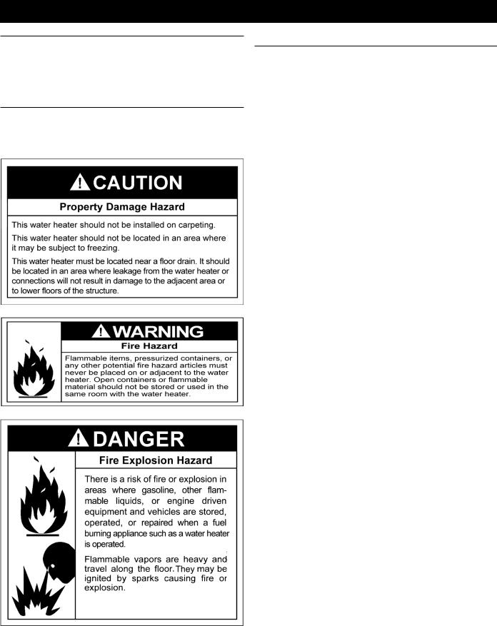
GENERAL REQUIREMENTS
REQUIRED ABILITY
Installation or service of this water heater requires ability equivalent to that of a licensed tradesman in the field involved. Plumbing, air supply, venting, gas supply, and electrical work are required.
LOCATION
When installing the water heater, consideration must be given to proper location. The location selected should provide ade quate air supply and be as centralized with the piping system as possible.
This water heater is intended for Indoor Installation only, and should not be installed where freezing temperatures or any moisture could damage the external components of the water heater.
REPLACING EXISTING COMMON VENTED WATER HEATER
NOTE: This section does not describe a method for common venting XWH units. It describes what must be done when a unit is removed from a common vent system. The XWH units require special vent systems and fans for common vent. Contact the factory if you have questions about common venting XWH units.
Whenanexistingwaterheaterisremovedfromacommonventing system, the common venting system is likely to be too large for proper venting of the appliances remaining connected to it.At the time of removal of an existing water heater, the following steps should be followed with each appliance remaining connected to the common venting system placed in operation, while the other appliances remaining connected to the common venting system are not in operation.
1.Seal any unused openings in the common venting system.
2.Visually inspect the venting system for proper size and horizontal pitch and determine there is no blockage or restriction, leakage, corrosion and deficiencies which could cause an unsafe condition.
3.In so far as it is practical, close all building doors and windows and all doors between the space in which the appliances remaining connected to the common venting system are located and other spaces of the building. Turn on clothes dryers and any appliance not connected to the common venting system. Turn on any exhaust fans, such as range hoods and bathroom exhausts, so they will operate at maximum speed. Do not operate a summer exhaust fan. Close fireplace dampers.
4.Place in operation the appliance being inspected. Follow the lighting instructions. Adjust thermostat so the appliance will operate continuously.
5.Test for spillage at the draft hood relief opening after 5 minutes of main burner operation. Use the flame of a match or candle, or smoke from a cigarette, cigar or pipe.
6.After it has been determined that each appliance remaining connected to the common venting system properly vents when tested as outlined above, return doors, windows, exhaust fans, fireplace dampers and any other gas-burning appliance to their previous condition of use.
7.Any improper operation of the common venting system should be corrected so that the installation conforms with the National Fuel Gas Code, ANSI Z223.1/NFPA 54 and/ or CSA B149.1, Installation Codes. When resizing any portion of the common venting system, the common venting system should be resized to approach the minimum size as determined using the appropriate tables and guidelines in the National Fuel Gas Code, ANSI Z223.1/NFPA 54 and/or CSA B149.1, Installation Codes.
20
PANELS AND COVERS
All panels and covers (e.g. control and junction box covers; front, side and rear panels of water heater) must be in place after service and/or before operation of water heater. This will ensure that all gas ignition components will be protected from water.
The XWH is a low-pressure water heater to be used as hot water heating (potable water only) applications.
CHEMICAL VAPOR CORROSION
Water heater corrosion and component failure can be caused by the heating and breakdown of airborne chemical vapors. Spray can propellants, cleaning solvents, refrigerator and air conditioning refrigerants, swimming pool chemicals, calcium and sodium chloride (water softener salt), waxes, and process chemicals are typical compounds which are potentially corrosive. These materials are corrosive at very low concentration levels with little or no odor to reveal their presence.
Products of this sort should not be stored near water heater. Also, air which is brought in contact with water heater should not contain any of these chemicals. If necessary, uncontaminated air should be obtained from remote or outside sources. Failure to observe this requirement will void warranty.
INSTALLATION CLEARANCES
This water heater is approved for installation in an alcove with minimum clearances to combustibles.
Table 11. INSTALLATION CLEARANCES
|
RECOMMENDED |
CLEARANCES FROM |
|
SERVICE |
COMBUSTIBLE |
|
CLEARANCES |
MATERIALS |
Front |
30" (762 mm) |
8" (203 mm) |
Rear |
36" (610 mm) |
24" (610 mm) |
Left |
24 " (610 mm) |
1" (25.4 mm) |
Right |
24 " (610 mm) |
2" (51 mm) |
Top |
24" (610 mm) |
6" (152 mm) |
2” (51 mm) clearance is allowable from combustible construction for hot water pipes.
Sufficient area should be provided at the front and rear of the unit for proper servicing. In a utility room installation, the door opening should be wide enough to allow the water heater to enter or to permit the replacement of another appliance such as a water heater.
FLOORING AND FOUNDATION:
All models are approved for installation on combustible flooring, but must never be installed on carpeting. Do not install the water heater on carpeting even if foundation is used. Fire can result, causing severe personal injury, death, or substantial property damage.
If flooding is possible, elevate the water heater sufficiently to prevent water from reaching the water heater.
LEVELING
Because this unit is a condensing unit, it has a condensation disposal system that requires this unit to be level to properly drain. Each unit should be checked to be certain that it is level prior to starting the unit.
If the unit is not level, obtain and insert shims under the feet at the frame base to correct this condition.
AIR REQUIREMENTS
Breathing Hazard - Carbon Monoxide Gas
 Install appliance in accordance with the Instruction Manual and NFPA 54 or CAN/CSA-B149.1.
 To avoid injury, combustion and ventilation air must be taken from outdoors.
 Do not place chemical vapor emitting products near water heater.
Breathing carbon monoxide can cause brain damage or death. Always read and understand instruction manual.
For safe operation an adequate supply of fresh uncontaminated air for combustion and ventilation must be provided.
An insufficient supply of air can cause recirculation of combustion products resulting in contamination that may be hazardous to life. Such a condition often will result in a yellow, luminous burner flame, causing sooting of the combustion chamber, burners and flue tubes and creates a risk of asphyxiation.
Do not install the water heater in a confined space unless an adequate supply of air for combustion and ventilation is brought in to that space using the methods described in the Confined Space section that follows.
Never obstruct the flow of ventilation air. If you have any doubts or questions at all, call your gas supplier. Failure to provide the proper amount of combustion air can result in a fire or explosion and cause property damage, serious bodily injury or death.
UNCONFINED SPACE
An unconfined space is one whose volume is not less than 50 cubic feet per 1,000 Btu/hr (4.8 cubic meters per kW) of the total input rating of all appliances installed in the space. Rooms communicating directly with the space, in which the appliances are installed, through openings not furnished with doors, are considered a part of the unconfined space.
Makeup air requirements for the operation of exhaust fans, kitchen ventilation systems, clothes dryers and fireplaces shall also be considered in determining the adequacy of a space to provide combustion, ventilation and dilution air.
UNUSUALLY TIGHT CONSTRUCTION
In unconfined spaces in buildings, infiltration may be adequate to provide air for combustion, ventilation and dilution of flue gases. However, in buildings of unusually tight construction (for example, weather stripping, heavily insulated, caulked, vapor barrier, etc.) additional air must be provided using the methods described in the Confined Space section that follows.
21
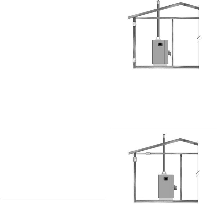
CONFINED SPACE |
|
OUTDOOR AIR THROUGH TWO OPENINGS |
A confined space is one whose volume is less than 50 cubic feet per 1,000 Btu/hr (4.8 cubic meters per kW) of the total input rating of all appliances installed in the space.
Openings must be installed to provide fresh air for combustion, ventilation and dilution in confined spaces. The required size for the openings is dependent on the method used to provide fresh air to the confined space and the total Btu/hr input rating of all appliances installed in the space.
DIRECT VENT APPLIANCES
Appliances installed in a direct vent configuration that derive all air for combustion from the outdoor atmosphere through sealed intake air piping are not factored in the total appliance input Btu/ hr calculations used to determine the size of openings providing fresh air into confined spaces.
EXHAUST FANS
Where exhaust fans are installed, additional air shall be provided to replace the exhausted air. When an exhaust fan is installed in the same space with a water heater, sufficient openings to provide fresh air must be provided that accommodate the requirements for all appliances in the room and the exhaust fan. Undersized openings will cause air to be drawn into the room through the waterheater’svent system causing poor combustion. Sooting, serious damage to the water heater and the risk of fire or explosion may result. It can also create a risk of asphyxiation.
LOUVERS AND GRILLES
The free areas of the fresh air openings in the instructions that follow do not take in to account the presence of louvers, grilles or screens in the openings.
The required size of openings for combustion, ventilation and dilution air shall be based on the “net free area” of each opening. Where the free area through a design of louver or grille or screen is known, it shall be used in calculating the size of opening required to provide the free area specified. Where the louver and grille design and free area are not known, it shall be assumed that wood louvers will have 25% free area and metal louvers and grilles will have 75% free area. Non motorized louvers and grilles shall be fixed in the open position.
FRESH AIR OPENINGS FOR CONFINED SPACES
The following instructions shall be used to calculate the size, number and placement of openings providing fresh air for combustion, ventilation and dilution in confined spaces. The illustrations shown in this section of the manual are a reference for the openings that provide fresh air into confined spaces only. Do not refer to these illustrations for the purpose of vent installation. See Venting section on Page 24 for complete venting installation instructions.
Figure 16. OUTDOOR AIR THROUGH TWO OPENINGS
The confined space shall be provided with two permanent openings, one commencing within 12 inches (300 mm) of the top and one commencing within 12 inches (300 mm) of the bottom of the enclosure. The openings shall communicate directly with the outdoors. See Figure 16.
Each opening shall have a minimum free area of 1 square inch per 4,000 Btu/hr (550 mm2 per kW) of the aggregate input rating of all appliances installed in the enclosure. Each opening shall not be less than 100 square inches (645 cm2).
OUTDOOR AIR THROUGH ONE OPENING
Figure 17. OUTDOOR AIR THROUGH ONE OPENING
Alternatively a single permanent opening, commencing within 12 inches (300 mm) of the top of the enclosure, shall be provided. See Figure 17. The water heater shall have clearances of at least 1 inch (25 mm) from the sides and back and 6 inches (150 mm) from the front of the appliance. The opening shall directly communicate with the outdoors or shall communicate through a vertical or horizontal duct to the outdoors or spaces that freely communicate with the outdoors and shall have a minimum free area of the following:
1.1 square inch per 3000 Btu/hr (700 mm2 per kW) of the total input rating of all appliances located in the enclosure, and
2.Not less than the sum of the areas of all vent connectors in the space.
22
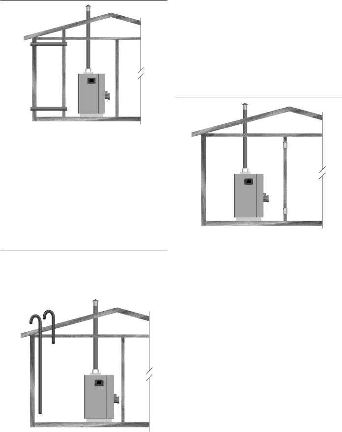
OUTDOOR AIR THROUGH TWO HORIZONTAL DUCTS
Figure 18. OUTDOOR AIR THROUGH TWO HORIZONTAL
DUCTS
The confined space shall be provided with two permanent horizontal ducts, one commencing within 12 inches (300 mm) of the top and one commencing within 12 inches (300 mm) of the bottom of the enclosure. The horizontal ducts shall communicate directly with the outdoors. See Figure 18.
Each duct opening shall have a minimum free area of 1 square inch per 2,000 Btu/hr (1100 mm2 per kW) of the aggregate input rating of all appliances installed in the enclosure.
When ducts are used, they shall be of the same cross sectional area as the free area of the openings to which they connect. The minimum dimension of rectangular air ducts shall be not less than 3 inches.
OUTDOOR AIR THROUGH TWO VERTICAL DUCTS
The illustrations shown in this section of the manual are a reference for the openings that provide fresh air into confined spaces only.
Do not refer to these illustrations for the purpose of vent installation.
Figure 19. OUTDOOR AIR THROUGH TWO VERTICAL
DUCTS
The confined space shall be provided with two permanent vertical ducts, one commencing within 12 inches (300 mm) of the top and one commencing within 12 inches (300 mm) of the bottom of the enclosure. The vertical ducts shall communicate directly with the outdoors. See Figure 19.
Each duct opening shall have a minimum free area of 1 square inch per 4,000 Btu/hr (550 mm2 per kW) of the aggregate input rating of all appliances installed in the enclosure.
When ducts are used, they shall be of the same cross sectional area as the free area of the openings to which they connect. The minimum dimension of rectangular air ducts shall be not less than 3 inches.
AIR FROM OTHER INDOOR SPACES
Figure 20. AIR FROM OTHER INDOOR SPACES
The confined space shall be provided with two permanent openings, one commencing within 12 inches (300 mm) of the top and one commencing within 12 inches (300 mm) of the bottom of the enclosure. See Figure 20.
Each opening shall communicate directly with an additional room(s) of sufficient volume so that the combined volume of all spaces meets the criteria for an Unconfined Space.
Each opening shall have a minimum free area of 1 square inch per 1,000 Btu/hr (1100 mm2 per kW) of the aggregate input rating of all appliances installed in the enclosure. Each opening shall not be less than 100 square inches (645 cm2).
23
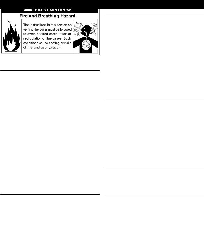
VENTING
VENT INSTALLATION CONSIDERATIONS
This water heater can be vented using room air for intake combustionair,ordirectventedsothatallintakeairforcombustion comes from the outside through a sealed pipe. When installing this appliance as direct vent, use the recommended terminations in this section, refer to Page 27 till Page 30.
In cold climates any water vapor remaining in the flue gases will condense into a cloud of vapor at the point where the vent system exits the building. Special consideration is recommended, before locating the vent termination near walkways, windows and building entrances.
Direct venting into dead spaces such as alleys, atriums, and insidecornerscancauserecirculationoffluegases. Recirculation of flue gases will cause sooting, premature failure of the heat exchanger, and icing of the combustion air intake during severe cold weather. To prevent the recirculation of flue gases, maintain as much distance as possible between the combustion air intake and the exhaust vent terminal. Due to large volumes of flue gases, multiple water heater applications also require additional distance between the intake and the exhaust terminals.
This water heater must be vented with Polypropylene, PVC/ CPVC or an UL approved AL 29-4C Stainless Steel venting material which are explained in the following pages. Vent sizing, installation and termination should be in accordance with this instruction manual.
All electrical power and gas must be turned off prior to any installation of the venting system.
GENERAL VENT INSTALLATION PROCEDURE
Prior to beginning the installation of the vent system, determine and obtain all parts required for the installation. Proper operation of the water heater and venting system is dependent upon use of all specified parts and installation techniques; both safety and proper performance of the system may suffer if instructions are not followed.
POLYPROPYLENE INSTALLATION:
AllXWHwaterheatersareshippedwithPolypropyleneventing kits out of the factory. These kits are in separate cartons along with the water heater shipment. They must be assembled and installed on the water heater as shown in Figure 21 & Figure 22. Using Centrocerin is recommended as an assembly lube for venting. Application of Centrocerin resists movement between the vent legths and fittings. The vent pipes must also be properly supported. The kit also includes a PVC/CPVC adapter, which can be discarded and will only be required for PVC/CPVC vent installations. A condensate trap is also supplied with the venting kit and needs to be piped separately in the field.
PVC/CPVC INSTALLATION:
Installation must comply with local requirements and with the National Fuel Gas Code, ANSI Z223.1 for U.S. installations or CSA B149.1 for Canadian installations.
Refer to Table 12 on Page 36 for PVC/CPVC piping materials.
PVC/CPVC Installation requires the use of factory supplied PVC/CPVC adapters.
All PVC vent pipes must be glued, properly supported, and the exhaust must be pitched a minimum of a 1/4 inch per foot back to the water heater (to allow drainage of condensate).
This water heater requires a special venting system. Use only the vent materials, primer, and cement specified in this manual to make the vent connections. Failure to follow this warning could result in fire, personal injury, or death.
NOTE: Make sure that for PVC venting installation, the first 10 feet (3 m) of vent must be CPVC and the set point temperature of the water heater must not exceed 200 °F.
STAINLESS STEEL INSTALLATION:
Installations must comply with applicable national, state, and local codes. Stainless steel vent systems must be listed as a UL1738 approved system for the United States and a ULC-S636 approved system for Canada.
The factory supplied polypropylene vent kit will not adapt to stainless steel installation. For using the water heater with stainless steel, contact factory or pre-order the unit with stainless steel kit.
Installation of the approved AL 29-4C stainless steel venting material should adhere to the stainless steel vent manufacturer’s installation instructions supplied with the vent system.
Refer to Table 13 and Table 14 on Page 36 for air intake and vent pipe sizes.
AIR INTAKE/VENT CONNECTIONS
1.Air Intake Adapter: Provides an inlet for combustion air directly to the unit from outdoors.
2.Vent Outlet: Provides an outlet for combustion gases to outdoors.
VENTING SYSTEM
This water heater may be installed in six separate orientations depending on the requirements of the building and the appliance. The installer must decide which method is most appropriate for each installation. These orientations are:
1.Vertical Termination - vertical vent termination through un-enclosed or enclosed areas with roof penetration, see Figure 23 on Page 28.
2.Through-the-Wall Termination (TWT) - horizontal vent termination directly through an outside wall, see Figure 24 on Page 28.
3.Horizontal Direct Vent - using TWT to exhaust flue products and PVC piping to bring combustion air to the water heater from the outside. See Figure 25 on Page 29 and Figure 28 on Page 30.
4.Vertical Direct Vent - using a vertical vent termination to exhaust flue products and PVC piping to bring combustion air to the water heater from outside, see Figure 26 on Page 29 and Figure 27 on Page 30.
24
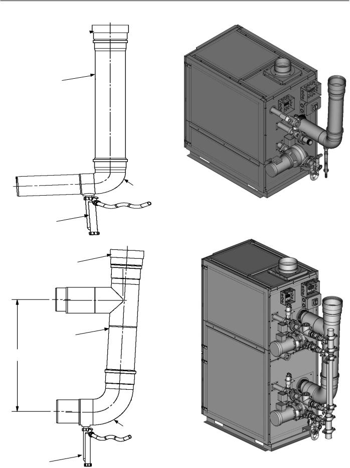
SUPPLIED VENT KIT:
PVC/CPVC ADAPTER
VENT PIPE
|
FUSED ELBOW |
VENT CONDENSATE TRAP |
Figure 21. POLYPROPYLENE INSTALLATION: SINGLE |
HEAT EXCHANGER WATER HEATER |
|
PVC/CPVC ADAPTER |
|
VENT PIPE
34 1/4"
|
FUSED ELBOW |
VENT CONDENSATE TRAP |
Figure 22. POLYPROPYLENE INSTALLATION: DOUBLE |
HEAT EXCHANGER WATER HEATER |
25

AIR INLET PIPE MATERIALS
Make sure the air inlet pipe(s) are sealed. The acceptable air inlet pipe materials are:
•PVC/CPVC
•Polypropylene
The opening on the air intake box will readily accept PVC/CPVC pipes. If air intake is Polypropylene, an adapter (use the ones provided with exhaust kit) is required. Adapter part numbers:
SIZE |
PART NUMBERS |
|
|
6" |
324400-000 |
|
|
8" |
324401-000 |
|
|
10" |
324402-000 |
|
|
Seal all joints and seams of the air inlet pipe using either Aluminum Foil Duct Tape meeting UL Standard 723 or 181A-P or a high quality UL Listed silicone sealant. Do not install seams of vent pipe on the bottom of horizontal runs.
Secure all joints with a minimum of 3 sheet metal screws or pop rivets. Apply Aluminum Foil Duct Tape or silicone sealant to all screws or rivets installed in the vent pipe.
Make sure that the air inlet pipes are properly supported.
The PVC/CPVC or Polypropylene air inlet pipe must be cleaned and sealed with the pipe manufacturer’s recommended solvents and standard commercial pipe cement for the material used.
The PVC/CPVC or Polypropylene air inlet pipe should use a silicone sealant to ensure a proper seal at the water heater connection and the air intake adapter connection. Proper sealing of the air inlet pipe ensures that combustion air will be free of
contaminants and supplied in proper volume.
REQUIREMENTS FOR INSTALLATION IN CANADA
1.Installations must be made with a vent pipe system certified to ULC-S636. IPEX is an approved vent manufacturer in Canada supplying vent material listed to ULC-S636.
2.The initial 3 feet (0.9 m) of plastic vent pipe from the water heater flue outlet must be readily accessible for visual inspection.
3.The components of the certified vent system must not be interchanged with other vent systems or unlisted pipe/ fittings.
VENT AND AIR PIPE INSTALLATION
1.Measure from the water heater level to vent. Refer to the Table 13 on Page 36 for the allowable lengths.
2.Prepare pipes to the required lengths and deburr the inside and outside of the pipe ends. Chamfer outside the pipe end to ensure even cement distribution when joining.
3.Clean all pipe ends and fittings using a clean dry rag. (Moisture will retard curing and dirt or grease will prevent adhesion.)
4.Dryfitventorairpipingtoensureproperfitbeforeassembling any joint. The pipe should go a third to two-thirds into the fitting to ensure proper sealing after cement is applied.
5.Priming and Cementing:
•Handle pipes and fittings carefully to prevent contamination of surfaces.
•Apply an even coat of primer to the fitting socket.
•Apply an even coat of primer to the pipe end to approximately 1/2" beyond the socket depth.
•Apply a second primer coat to the fitting socket.
•While primer is still wet, apply an even coat of approved cement to the pipe equal to the depth of the fitting socket.
•While primer is still wet, apply an even coat of approved cement to the fitting socket.
•Apply a second coat of cement to the pipe.
•While the cement is still wet, insert the pipe into the fitting, if possible twist the pipe a 1/4 turn as you insert it.
NOTE: If voids are present, sufficient cement was not applied and joint could be defective.
•Clear excess cement from the joint removing ring or beads as it will needlessly soften the pipe.
When a sidewall or vertical rooftop combustion air supply system is disconnected for any reason, the air inlet pipe must be resealed to ensure that combustion air will be free of contaminants and supplied in proper volume.
Failure to properly seal all joints and seams may result in flue gas recirculation, spillage of flue products and carbon monoxide emissions causing severe personal injury or death.
26
Loading...