


 Loading...
IMPORTANT SAFETY INSTRUCTIONS
CAUTION
RISK OF ELECTRIC SHOCK
DO NOT OPEN
CAUTION: TO REDUCE THE RISK OF ELECTRIC
SHOCK, DO NOT REMOVE COVER (OR BACK). NO
USER-SERVICEABLE PARTS INSIDE. REFER
SERVICING TO QUALIFIED SERVICE PERSONNEL.
The lightning flash with arrowhead symbol within an equilateral triangle is intended to alert the user to the presence of uninsulated “dangerous voltage” within the product’s enclosure that may be of sufficient magnitude to constitute a risk of electric shock to persons.
The exclamation point within an equilateral triangle is intended to alert the user to the presence of important operating and maintenance (servicing) instructions in the literature accompanying the appliance.
1.Read these instructions.
2.Keep these instructions.
3.Heed all warnings.
4.Follow all instructions.
5.Do not use this apparatus near water.
6.Clean only with a dry cloth.
7.Do not block any of the ventilation openings. Install in accordance with the manufacturer’s instructions.
8.Do not install near any heat sources such as radiators, heat registers, stoves or other apparatus (including amplifiers) that produce heat.
9.Do not defeat the safety purpose of the polarized or grounding-type plug. A polarized plug has two blades with one wider than the other. A grounding-type plug has two blades and a third grounding prong. The wide blade or the third prong is provided for your safety. When the provided plug does not fit into your outlet, consult an electrician for replacement of the obsolete outlet.
10.Protect the power cord from being walked on or pinched, particularly at plugs, convenience receptacles and the point where they exit from the apparatus.
11.Only use the attachments/accessories specified by the manufacturer.
12.Use only with a cart, stand, tripod, bracket or table specified by the manufacturer, or sold with the apparatus. When a cart is used, use caution when moving the cart/apparatus combination to avoid injury from tip-over.
13.Unplug this apparatus during lightning storms or when unused for long periods of time.
14.Refer all servicing to qualified service personnel. Servicing is required when the apparatus has been damaged in any way, such as power supply cord or plug is damaged, liquid has been spilled or objects have fallen into the apparatus, the apparatus has been exposed to rain or moisture, does not operate normally, or has been dropped.

WARNING: To reduce the risk of fire or electric shock, do not expose this apparatus to rain or moisture. Avoid installing this unit where foreign objects may fall onto this unit and/or this unit may be exposed to liquid dripping or splashing. On the top of this unit, do not place:
•Burning objects (i.e. candles), as they may cause fire, damage to this unit, and/or personal injury.
•Containers with liquid in them, as they may fall and liquid may cause electrical shock to the user and/or damage to this unit.
Apparatus shall not be exposed to dripping or splashing and no objects filled with liquids, such as vases, shall be placed on the apparatus.
Do not install this equipment in a confined space such as a case or similar. Install it away from direct sunlight, heat sources, vibration, dust, moisture, and/or cold.
Do not cover this unit with a newspaper, tablecloth, curtain, etc. in order not to obstruct heat radiation. If the temperature inside this unit rises, it may cause fire, damage to this unit, and/or personal injury.
Install this unit near the AC outlet and where the AC power plug can be reached easily.
This unit is not disconnected from the AC power source as long as the Main Power Switch on the rear panel is ON. This state is called the standby mode. In this state, this unit is designed to consume a very small quantity of power.
NOTE: This product is not an auto voltage Receiver. Connect only to the prescribed AC outlet, i.e., 120V 60Hz or 230V 50Hz.
CAUTION: These servicing instructions are for use by qualified service personnel only. To reduce the risk of electric shock, do not perform any servicing other than that contained in the operating instructions, unless you are qualified to do so.
CAUTION: Changes or modifications to this equipment not expressly approved by Paradigm Electronics for compliance could void the user’s authority to operate this equipment.
FCC WARNING: Changes or modifications not expressly approved by the party responsible for compliance could void the user’s authority to operate the equipment.
This equipment has been tested and found to comply with the limits for a class B digital device, pursuant to part 15 of the FCC Rules. These limits are designed to provide reasonable protection against harmful interference in a residential installation. This equipment generates, uses and can radiate radio frequency energy and, if not installed and used in accordance with the instructions, may cause harmful interference to radio communications. However, there is no guarantee that interference will not occur in a particular installation. If this equipment does cause harmful interference to radio or television reception, which can be determined by turning the equipment off and on, the user is encouraged to try to correct the interference by one or more of the following measures:
•Reorient or relocate the receiving antenna.
•Increase the separation between the equipment and receiver.
•Connect the equipment into an outlet on a circuit different from that to which the receiver is connected.
•Consult the dealer or an experienced radio / TV technician for help.
DO NOT LOCATE IN THE FOLLOWING PLACES:
To ensure long-lasting use, do not locate the unit:
•Exposed to direct sunlight.
•Near sources of heat such as heaters.
•Highly humid or poorly ventilated.
•Dusty.
•Subjected to mechanical vibrations.
•On wobbly, inclined, or otherwise unstable surfaces.
•Near windows where there is a chance of exposure to rain, etc.
•On top of an amplifier or other component which dissipates a great deal of heat.
To ensure proper heat radiation ensure clearance from walls and other equipment according to diagram.
|
|
|
|
|
|
|
|
|
|
|
|
|
|
|
|
|
|
|
|
|
|
|
|
|
|
|
|
|
|
|
|
|
|
|
|
|
|
Left 0.2 m (8 in) |
|
|
|
|
|
|
|
|
Above 0.2 m |
|
|
|
|
|
|
Right 0.2 m |
|
||||||||||||||||||
|
|
|
|
|
|
|
|
|
|
|
|
|
|
|||||||||||||||||||||||
|
or more |
|
|
|
|
|
|
|
|
(8 in) or more |
|
|
|
|
(8 in) or more |
|
||||||||||||||||||||
|
|
|
|
|
|
|
|
|
|
|
|
|||||||||||||||||||||||||
|
|
|
|
|
|
|
|
|
|
|
|
|
|
|
|
|
|
|
|
|
|
|
|
|
|
|
|
|
|
|
|
|
|
|
|
|
|
|
|
|
|
|
|
|
|
|
|
|
|
|
|
|
|
|
|
|
|
|
|
|
|
|
|
|
|
|
|
|
|
|
|
|
|
|
|
|
|
|
|
|
|
|
|
|
|
|
|
|
|
|
|
|
|
|
|
|
|
|
|
|
|
|
|
|
|
|
|
|
|
|
|
|
|
|
|
|
|
|
|
|
|
|
|
|
|
|
|
|
|
|
|
|
|
|
|
|
|
|
|
|
|
|
|
|
|
|
|
|
|
|
|
|
|
|
|
|
|
|
|
|
|
|
|
|
|
|
|
|
|
|
|
|
|
|
|
|
|
|
|
|
|
|
|
|
|
|
|
|
|
|
|
|
|
|
|
|
|
|
|
|
|
|
|
|
|
|
|
|
|
|
|
|
|
|
|
|
|
|
|
|
|
|
|
|
|
|
|
|
|
|
|
|
|
|
|
|
|
|
|
|
|
|
|
|
|
|
|
|
|
|
|
|
|
|
|
|
|
|
|
|
|
|
|
|
|
|
|
|
|
|
|
|
|
|
|
|
|
|
|
|
|
|
|
|
|
|
|
|
|
|
|
|
|
|
|
|
|
|
|
|
|
|
|
|
|
|
|
|
|
|
|
|
|
|
|
|
|
|
|
|
|
|
|
|
|
|
|
|
|
|
|
|
|
|
|
|
|
|
|
|
|
|
|
|
|
|
|
|
|
|
|
|
|
|
|
|
|
|
|
|
|
|
|
|
|
|
|
|
|
Behind 0.2 m (8 in) or more

IMPORTANT INFORMATION FOR UK CUSTOMERS: DO NOT cut off the mains plug from this equipment. If the plug fitted is not suitable for the power points in your home or the cable is too short to reach a power point, then obtain an appropriate safety approved extension lead or consult your dealer. If, nonetheless, the mains plug is cut off, REMOVE THE FUSE and dispose of the PLUG immediately, to avoid possible shock hazard by inadvertent connection to the mains supply. If this product is not provided with a mains plug, or one has to be fitted, then follow the instructions given below:
IMPORTANT: DO NOT make any connection to the larger terminal which is marked with the letter “E” or by the safety earth symbol or colored GREEN or GREEN AND YELLOW.
The wires in the mains lead on this product are colored in accordance with the following code:
BLUE – NEUTRAL
BROWN – LIVE
As these colors may not correspond with the colored markings identifying the terminals in your plug, proceed as follows:
The BLUE wire must be connected to the terminal marked with the letter “N” or colored BLACK.
The BROWN wire must be connected to the terminal marked with the letter “L” or colored RED.
When replacing the fuse, only a correctly rated and approved type should be used, and be sure to re-fit the fuse cover.
If in doubt consult a competent electrician.

NOTES ON ENVIRONMENTAL PROTECTION
At the end of its useful life, this product must not be disposed of with regular household waste but must be returned to a collection point for the recycling of electrical and electronic equipment. The symbol on the product, user’s manual and packaging, point this out. The materials can be reused in accordance with their markings. Through re-use, recycling of raw materials or other forms of recycling of old products, you are making an important contribution to the protection of our environment. Your local administrative office can advise you of the responsible waste disposal point.
INFORMATION ABOUT COLLECTION AND DISPOSAL OF WASTE BATTERIES (DIRECTIVE 2006/66/EC OF THE EUROPEAN PARLIAMENT AND THE COUNCIL OF EUROPEAN UNION) (for European customers only)
Batteries bearing any of these symbols indicate that they should be treated as “separate collection” and not as municipal waste. It is encouraged that necessary measures are implemented to maximize the separate collection of waste batteries and to minimize the disposal of batteries as mixed municipal waste. End-users are exhorted not to dispose waste batteries as unsorted municipal waste. In order to achieve a high level of recycling waste batteries, discard waste batteries separately and properly through an accessible collection point in your vicinity. For more information about collection and recycling of waste batteries, please contact your local municipality, your waste disposal service or the point of sale where you purchased the items.
By ensuring compliance and conformance to proper disposal of waste batteries, potential hazardous effects on human health is prevented and the negative impact of batteries and waste batteries on the environment is minimized, thus contributing to the protection, preservation and quality improvement of the environment.
|
|
|
|
|
|
|
|
|
|
|
|
|
|
|
|
|
|
|
|
|
|
|
|
|
|
|
|
|
|
|
|
|
|
|
|
|
|
|
|
|
|
|
|
|
|
|
|
|
|
|
|
|
|
|
|
|
|
|
|
|
|
|
|
|
|
|
|
|
|
|
|
|
|
|
|
|
|
|
|
|
|
|
|
|
|
|
|
|
|
|
|
|
|
|
|
|
|
|
|
|
|
|
|
|
|
|
|
|
|
|
|
|
|
|
|
|
|
|
|
|
|
|
|
|
|
|
|
|
|
|
|
|
|
|
|
|
|
|
|
|
|
|
|
|
|
|
|
|
|
|
|
|
|
|
|
|
|
|
|
|
|
|
|
|
|
|
|
|
|
|
|
|
|
|
|
|
|
|
|
|
|
|
|
|
|
|
|
|
|
|
|
|
|
|
|
|
|
|
|
|
|
|
|
|
|
|
|
|
|
|
|
|
|
|
|
|
|
|
|
|
|
|
|
|
|
|
|
|
|
|
|
|
|
|
|
|
|
|
|
|
|
|
|
|
|
|
|
|
|
|
|
|
|
|
|
|
|
Pb |
|
|
|
|
|
Hg |
|
|
|
|
|
Cd |
|
|
||||||
Anthem and any related party assume no liability for the user’s failure to comply with any requirements.
Anthem, AnthemLogic, ARC, Sonic Frontiers, and Paradigm are trademarks or registered trademarks of Paradigm Electronics Inc. Copyright Paradigm Electronics Inc. All rights reserved. The information contained herein may not be reproduced in whole or in part without our express written permission. We reserve the right to change specifications and/or features without notice as design improvements are incorporated.
Manufactured under license from Dolby Laboratories. Dolby, Pro Logic, and the double-D symbol are trademarks of Dolby Laboratories.
Manufactured under license under U.S. Patent #’s: 5,451,942; 5,956,674; 5,974,380; 5,978,762; 6,226,616; 6,487,535; 7,212,872; 7,333,929; 7,392,195; 7,272,567 & other U.S. and worldwide patents issued & pending. DTS and the Symbol are registered trademarks, & DTS-HD, DTS-HD Master Audio, and the DTS logos are trademarks of DTS, Inc. Product includes software. © DTS, Inc. All Rights Reserved.
This item incorporates copy protection technology that is protected by U.S. patents and other intellectual property rights of Rovi Corporation. Reverse engineering and disassembly are prohibited.
HDMI, the HDMI logo and High-Definition Multimedia Interface are trademarks or registered trademarks of HDMI Licensing LLC.
iPhone and iPod are registered trademarks of Apple Inc., registered in the U.S. and other countries.
(MRX 700 US model only) HD Radio™ Technology Manufactured under license from iBiquity Digital Corp. U.S. and Foreign Patents. HD Radio™ and the HD Radio logo are proprietary trademarks of iBiquity Digital Corp.
All other trademarks are the property of their respective owners.

TABLE of CONTENTS
SECTION |
PAGE |
 1. INTRODUCTION
1.1 Before Making Connections. . . . . . . . . . . . . . . . . . . . . . . . . . . . . . . . . . . . . . . . . . . . . . . . . . . . . . . . . . . . . 1
1.2 In-Use Notices . . . . . . . . . . . . . . . . . . . . . . . . . . . . . . . . . . . . . . . . . . . . . . . . . . . . . . . . . . . . . . . . . . . . . . . . 1
1.3 Front Panel . . . . . . . . . . . . . . . . . . . . . . . . . . . . . . . . . . . . . . . . . . . . . . . . . . . . . . . . . . . . . . . . . . . . . . . . . . . . 2
1.4 Front Panel Display . . . . . . . . . . . . . . . . . . . . . . . . . . . . . . . . . . . . . . . . . . . . . . . . . . . . . . . . . . . . . . . . . . . . . 3
1.5 Rear Panel . . . . . . . . . . . . . . . . . . . . . . . . . . . . . . . . . . . . . . . . . . . . . . . . . . . . . . . . . . . . . . . . . . . . . . . . . . . . 4
1.6 Remote Controls . . . . . . . . . . . . . . . . . . . . . . . . . . . . . . . . . . . . . . . . . . . . . . . . . . . . . . . . . . . . . . . . . . . . . . . 5
1.7 Speaker Placement . . . . . . . . . . . . . . . . . . . . . . . . . . . . . . . . . . . . . . . . . . . . . . . . . . . . . . . . . . . . . . . . . . . . . 6
 2. CONNECTIONS
2.1 Video . . . . . . . . . . . . . . . . . . . . . . . . . . . . . . . . . . . . . . . . . . . . . . . . . . . . . . . . . . . . . . . . . . . . . . . . . . . . . . . . . 7
2.2 Audio . . . . . . . . . . . . . . . . . . . . . . . . . . . . . . . . . . . . . . . . . . . . . . . . . . . . . . . . . . . . . . . . . . . . . . . . . . . . . . . . . 8
2.3 Antennas . . . . . . . . . . . . . . . . . . . . . . . . . . . . . . . . . . . . . . . . . . . . . . . . . . . . . . . . . . . . . . . . . . . . . . . . . . . . . . 8
2.4 Ethernet . . . . . . . . . . . . . . . . . . . . . . . . . . . . . . . . . . . . . . . . . . . . . . . . . . . . . . . . . . . . . . . . . . . . . . . . . . . . . . . 9
2.5 MDX 1 Dock (optional) . . . . . . . . . . . . . . . . . . . . . . . . . . . . . . . . . . . . . . . . . . . . . . . . . . . . . . . . . . . . . . . . . . 9
2.6 12V Trigger . . . . . . . . . . . . . . . . . . . . . . . . . . . . . . . . . . . . . . . . . . . . . . . . . . . . . . . . . . . . . . . . . . . . . . . . . . . . 9
2.7 Infra Red Input . . . . . . . . . . . . . . . . . . . . . . . . . . . . . . . . . . . . . . . . . . . . . . . . . . . . . . . . . . . . . . . . . . . . . . . . . 9
2.8 Infra Red Output . . . . . . . . . . . . . . . . . . . . . . . . . . . . . . . . . . . . . . . . . . . . . . . . . . . . . . . . . . . . . . . . . . . . . . . . 9
2.9 Switched AC Outlet . . . . . . . . . . . . . . . . . . . . . . . . . . . . . . . . . . . . . . . . . . . . . . . . . . . . . . . . . . . . . . . . . . . . . 9
2.10 Power. . . . . . . . . . . . . . . . . . . . . . . . . . . . . . . . . . . . . . . . . . . . . . . . . . . . . . . . . . . . . . . . . . . . . . . . . . . . . . . . . 9
 3. SETUP
Navigating in the Setup Menu. . . . . . . . . . . . . . . . . . . . . . . . . . . . . . . . . . . . . . . . . . . . . . . . . . . . . . . . . . . . . . . 13
Quick Setup . . . . . . . . . . . . . . . . . . . . . . . . . . . . . . . . . . . . . . . . . . . . . . . . . . . . . . . . . . . . . . . . . . . . . . . . . . . . . . . 14
3.1 Video Output Configuration . . . . . . . . . . . . . . . . . . . . . . . . . . . . . . . . . . . . . . . . . . . . . . . . . . . . . . . . . . . . 14
3.2 Speaker Configuration. . . . . . . . . . . . . . . . . . . . . . . . . . . . . . . . . . . . . . . . . . . . . . . . . . . . . . . . . . . . . . . . . 15
3.3 Listener Position . . . . . . . . . . . . . . . . . . . . . . . . . . . . . . . . . . . . . . . . . . . . . . . . . . . . . . . . . . . . . . . . . . . . . . 16
3.4 Level Calibration . . . . . . . . . . . . . . . . . . . . . . . . . . . . . . . . . . . . . . . . . . . . . . . . . . . . . . . . . . . . . . . . . . . . . 17
3.5 Source Setup . . . . . . . . . . . . . . . . . . . . . . . . . . . . . . . . . . . . . . . . . . . . . . . . . . . . . . . . . . . . . . . . . . . . . . . . . 19
3.6 Listening Mode Presets. . . . . . . . . . . . . . . . . . . . . . . . . . . . . . . . . . . . . . . . . . . . . . . . . . . . . . . . . . . . . . . . 21
3.7 Video Mode Presets . . . . . . . . . . . . . . . . . . . . . . . . . . . . . . . . . . . . . . . . . . . . . . . . . . . . . . . . . . . . . . . . . . . 22
3.8 Displays and Timeout. . . . . . . . . . . . . . . . . . . . . . . . . . . . . . . . . . . . . . . . . . . . . . . . . . . . . . . . . . . . . . . . . . 23
3.9 Trigger Configuration . . . . . . . . . . . . . . . . . . . . . . . . . . . . . . . . . . . . . . . . . . . . . . . . . . . . . . . . . . . . . . . . . . 24
3.10 General Configuration . . . . . . . . . . . . . . . . . . . . . . . . . . . . . . . . . . . . . . . . . . . . . . . . . . . . . . . . . . . . . . . . . 25
3.11 Anthem Room Correction (ARC) . . . . . . . . . . . . . . . . . . . . . . . . . . . . . . . . . . . . . . . . . . . . . . . . . . . . . . . . 26
3.12 Multimedia. . . . . . . . . . . . . . . . . . . . . . . . . . . . . . . . . . . . . . . . . . . . . . . . . . . . . . . . . . . . . . . . . . . . . . . . . . . 30

 4. OPERATION
4.1 |
Power On and Off . . . . . . . . . . . . . . . . . . . . . . . . . . . . . . . . . . . . . . . . . . . . . . . . . . . . . . . |
. . . . . . . . . . . . . . 31 |
|
4.2 |
Zone Selection . . . . . . . . . . . . . . . . . . . . . . . . . . . . . . . . . . . . . . . . . . . . . . . . . . . . . . . . . . |
. . . . . . . . . . . . . 31 |
|
4.3 |
Source Selection . . . . . . . . . . . . . . . . . . . . . . . . . . . . . . . . . . . . . . . . . . . . . . . . . . . . . . . . |
. . . . . . . . . . . . . 31 |
|
|
4.3.1 |
Tuner |
32 |
|
4.3.2 |
Multimedia |
32 |
4.4 |
Level Trim |
. . . . . . . . . . . . . . . . . . . . . . . . . . . . . . . . . . . . . . . . . . . . . . . . . . . . . . . . . . . . . |
. . . . . . . . . . . . . . 33 |
4.5 |
Audio Adjustments . . . . . . . . . . . . . . . . . . . . . . . . . . . . . . . . . . . . . . . . . . . . . . . . . . . . . . |
. . . . . . . . . . . . . 33 |
|
4.6 |
Listening Modes . . . . . . . . . . . . . . . . . . . . . . . . . . . . . . . . . . . . . . . . . . . . . . . . . . . . . . . . . |
. . . . . . . . . . . . . 33 |
|
|
4.6.1 |
AnthemLogic |
34 |
|
4.6.2 |
Dolby Digital 2.0 |
35 |
|
4.6.3 Surround Modes for 2.0-Channel Sources |
35 |
|
|
4.6.4 |
Dolby Virtual Speaker |
35 |
|
4.6.5 |
Dolby Digital |
36 |
|
4.6.6 |
DTS |
36 |
|
4.6.7 Dolby Volume and Dynamic Range Control |
37 |
|
4.7 |
Resolution |
. . . . . . . . . . . . . . . . . . . . . . . . . . . . . . . . . . . . . . . . . . . . . . . . . . . . . . . . . . . . . |
. . . . . . . . . . . . . . 37 |
4.8 |
Display Brightness . . . . . . . . . . . . . . . . . . . . . . . . . . . . . . . . . . . . . . . . . . . . . . . . . . . . . . |
. . . . . . . . . . . . . 37 |
|
4.9 |
Sleep Timer . . . . . . . . . . . . . . . . . . . . . . . . . . . . . . . . . . . . . . . . . . . . . . . . . . . . . . . . . . . . . |
. . . . . . . . . . . . . . 37 |
|
4.10 |
Info Display . . . . . . . . . . . . . . . . . . . . . . . . . . . . . . . . . . . . . . . . . . . . . . . . . . . . . . . . . . . . . |
. . . . . . . . . . . . . 38 |
|
4.11 |
Software Upgrade – Multimedia Section (not available on MRX 300) . . . . . . . . . . |
. . . . . . . . . . . . . . 38 |
|
4.12 |
Software Upgrade – Main Section. . . . . . . . . . . . . . . . . . . . . . . . . . . . . . . . . . . . . . . . . |
. . . . . . . . . . . . . . 38 |
|
Specifications |
|
|
39 |
Limited Warranty |
|
|
41 |
Big Pictures of Front and Rear Panels |
Inside Back Cover |
||

1. INTRODUCTION
Thank you for purchasing the Anthem MRX series receiver.
The MRX 300, MRX 500, and MRX 700 receivers are cutting-edge home theater audio components with HDMI switching and video upconversion, multimedia and second zone capabilities, FM/AM tuner, HD Radio™ reception (MRX 700 120V model) and connection for optional MDX 1 iPod / iPhone dock.
Anthem products are engineered to recreate the passion of live performance and thrill of the best movie theaters by using the highest level of circuit design, proprietary software, superior build quality, innovative features, and intuitive ergonomics with tremendous flexibility.
1.1BEFORE MAKING CONNECTIONS
Check that you have received everything listed below and report discrepancies to your dealer as soon as possible. In case they are needed one day, keep the packing materials and the invoice that you received from your authorized Anthem dealer at time of purchase – without it, service will not be provided under warranty.
Packing List:
• |
MRX Receiver |
• |
FM antenna |
• Zone 2 remote control |
|
• |
Main remote control |
• |
AM loop antenna |
• |
CR2025 battery |
• |
2 AAA batteries |
|
|
• |
IEC power cord (US or EU type only) |
Additional items with Anthem Room Correction (ARC):
• |
Software installation CD |
• |
Microphone and clip |
• Telescopic stand |
• |
Serial extension cable |
• |
USB microphone cable |
|
Serial Number:
•While it’s accessible, record it here for future reference
1.2IN-USE NOTICES
•Disconnect the power cord before connecting or disconnecting any components.
•If the receiver was transported or stored in the cold, let it warm to room temperature before use.
•Due to continuing advances operational characteristics may change. If this manual contains discrepancies please check www.anthemAV.com for the latest manual or software.
1

1.INTRODUCTION continued …
1.3FRONT PANEL (MRX 700 US model shown, others are similar)
1 |
|
|
2 |
3 |
4 |
|
5 |
12 |
11 |
10 |
9 |
|
8 |
7 |
6 |
1 |
– Navigation buttons for setup and multimedia |
7 |
– Main / Zone 2 selection |
||
2 |
– Remote control sensor location |
8 |
– |
Display brightness |
|
3 |
– |
Display |
9 |
– Sliding cover for front connections |
|
4 |
– |
Input selection |
10 |
– |
Front AV input |
5 |
– Volume and level functions |
11 |
– |
USB input (5VDC/0.5A) (not available on MRX 300) |
|
6 |
– |
Power on / standby |
12 |
– |
Headphone connection* |
*Uses Dolby Headphone to process 5.1-channel content so none of it is lost in the 2-channel headphone downmix.
For a larger diagram see inside back cover.
2
1. INTRODUCTION continued …
1.4 FRONT PANEL DISPLAY
MAIN Display Example:
1 
 2
2
|
BDP |
1080p |
|
|
Dolby TrueHD 3/4 |
|
|
4 |
|
3 |
|
1 – Source selection.
2 – Video input resolution.
3– Number of front/surround channels.
4– Audio format.
Tuner Display Example:
1 |
2 |
FM-01 101.3
Stereo -35
1 – Band and preset.
2 – Frequency. AM is tuned to nearest 10 kHz (120V model) or 9 kHz (230V model).
3

1. INTRODUCTION continued …
1.5REAR PANEL (MRX 700 US model shown, others are similar)
1 |
2 |
3 |
|
4 |
5 |
6 |
|
7 |
8 |
9 |
10 |
20 |
19 |
18 |
17 |
16 |
15 |
14 |
13 |
|
|
12 |
11 |
1 |
– Connection for optional MDX 1 dock |
11 |
– |
Switched AC outlet (50W maximum output)* |
|
2 |
– |
HDMI output |
12 |
– |
AC input |
3 |
– Ethernet connection (not available on MRX 300) |
13 |
– |
Component video outputs (via scaler) |
|
4 |
– |
USB input (5VDC/0.5A) (not available on MRX 300) |
14 |
– |
Speaker connections |
5 |
– |
HDMI inputs |
15 |
– |
Record audio outputs |
6 |
– |
Tuner antenna connections |
16 |
– |
Analog audio L/R inputs |
7 |
– Coaxial and optical digital audio outputs |
17 |
– |
RS-232 interface (bidirectional) |
|
8 |
– |
Composite video inputs |
18 |
– |
Main pre-out connections |
9 |
– Coaxial and optical digital audio inputs |
19 |
– |
IR and trigger connections |
|
10 |
– |
Component video inputs |
20 |
– |
Zone 2 audio outputs |
*AC outlet may not be available depending on country
For a larger diagram see inside back cover.
4
1. INTRODUCTION continued …
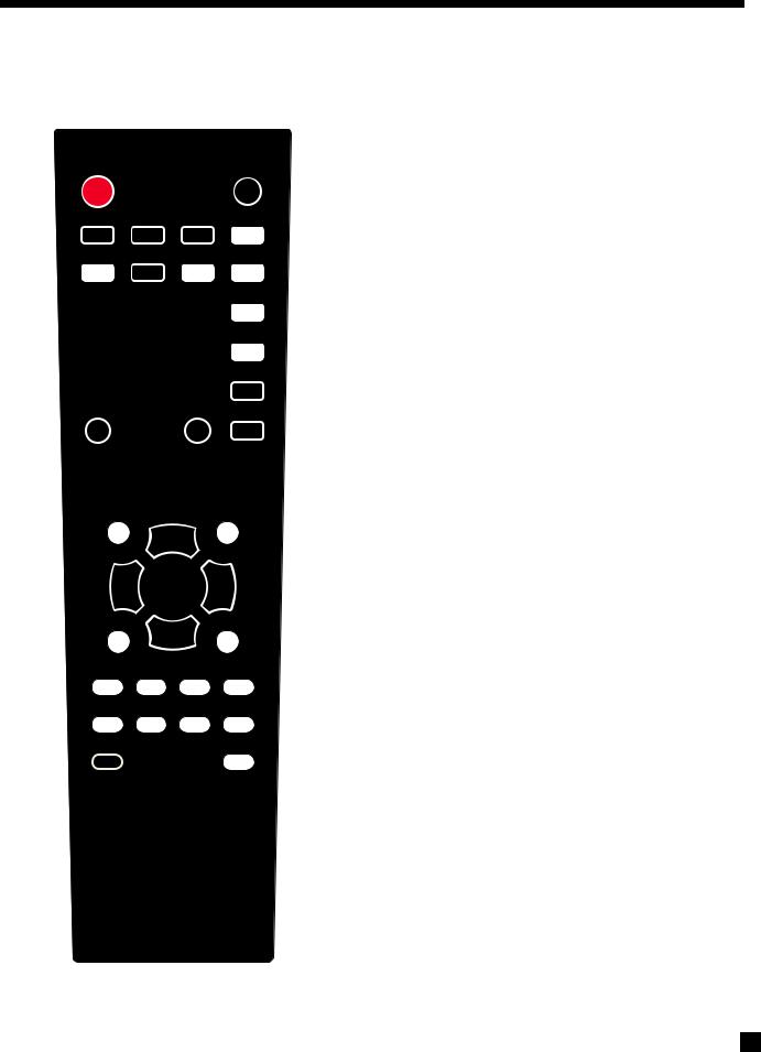
1.6REMOTE CONTROLS
1 |
|
|
|
|
|
|
|
|
|
1 |
– Main zone power on |
||||
2 |
2 |
– Main zone power off |
|||||
|
|
3 |
– Zone 2 power and mute |
||||
3 |
4 |
– Sleep control |
|||||
|
|
5 |
– Front panel dimmer control |
||||
4 |
6 |
– Main zone audio controls |
|||||
5 |
7 |
– Tuner presets control |
|||||
|
|
8 |
– Main video output resolution control |
||||
|
6 |
9 |
– Navigation and tuner controls |
||||
|
10 |
– Input selectors |
|||||
|
|
||||||
|
|
11 |
– Backlight control |
||||
|
|
12 |
– Multimedia controls |
||||
7 |
|
Zone 2 remote control: |
|||||
|
|
|
|||||
8 |
|
|
|
|
|
|
|
|
|
|
|
|
|
|
|
|
|
|
|
|
|
|
|
ZONE 2
9
10
11
12
Note: MRX 300/500/700 cannot access MEDIA from Zone 2
5

1. INTRODUCTION continued …
1.7SPEAKER PLACEMENT
The illustration below shows typical 7.1-channel speaker placement. The subwoofer can be placed in any location where severe resonances are prevented – details are in section 3.11 under “Quick Measure”.
back speakers are not used in a 5.1 system
The illustration below shows 7.1-channel speaker placement for use with Dolby Pro Logic IIz.
6

2. CONNECTIONS
2.1VIDEO CONNECTIONS
To configure inputs see section 3.5 and to configure video outputs see section 3.1.
HDMI:
Video is sent with audio from source components to the receiver. Maximum video resolution is 1080p60. Connect MAIN HDMI output to a display with HDMI input – one with High-bandwidth Digital Content Protection (HDCP) is required to display copy-protected material. Note that disc players usually enable HDCP even on home movies where copy protection was not seleced.
Before calling for technical support due to bad, intermittent, or no picture via HDMI:
1080p uses twice the bandwidth that 720p and 1080i do – make sure that the cable is suitable for the application otherwise the picture may contain pixel dropouts or not play at all.
Use High Speed HDMI cables. This is a requirement for all connecting devices including extenders when connecting a display that supports 1080p. Connecting devices that worked in an older setup may not work with Deep Color. If the source allows Deep Color to be turned off, start troubleshooting by turning it off. 12-bit Deep Color that works at 1080p24 may not work at 1080p50 or 1080p60.
Be careful when connecting HDMI cables. The connector should easily slide in the jack – do not insert it on an angle and do not force it. Each connector contains 19 delicate pins and damaged pins can damage jacks. Such damaged jacks are not covered by warranty. If your HDMI cables have been connected enough times that they are about to wear out, we recommend that you replace them.
If using adapters and are having a connection problem, start troubleshooting by eliminating the adapter.
Cable and satellite receivers: Many disable their component video output once HDMI is connected. To use the cable/satellite box in a secondary zone that uses component video, connect the box to the receiver via component, not HDMI.
Older cable and satellite receivers: HDMI connection may be problematic especially when output resolution changes between SD, 720p, and 1080i according to the channel. In such a case use component video connection instead, with coaxial or optical connection for audio.
Component Video:
Component video uses three coaxial cables and has a maximum resolution of 1080p when unprocessed or 480p when the source is copy-protected with Macrovision. Maximum input resolution is 1080i60 where the input is processed or converted to HDMI.
Composite Video:
Maximum resolution is 480i (NTSC) / 576i (PAL). This traditional format combines the black/white and color information for transmission on a single coaxial cable. To be displayed, the information has to be filtered and separated, a process that degrades video quality.
7

2. CONNECTIONS continued …
2.2AUDIO CONNECTIONS
Digital Audio Inputs and Outputs:
Digital audio sources can be connected with a coaxial, optical, or HDMI cable. These carry 2-channel PCM, Dolby Digital, and DTS. The HDMI inputs also accept up to eight channels of PCM.
Use the HDMI inputs if your display has HDCP-compliant HDMI or DVI input, otherwise use the coaxial or optical inputs. Any digital input can be assigned to any number of sources that are set to digital. Should you need audio from the HDMI output to your display, it’s 2-channel PCM. To change digital audio connection from factory default, see section 3.5.
Digital Rec-Out can provide a signal to the digital audio input of a Mini Disc recorder, CD recorder etc. from any coaxial or optical audio source.
Analog Audio Inputs and Outputs:
Analog audio connections are made with RCA connectors. To use ZONE2 or RECORD analog outputs, connect digital and analog audio and video from digital sources (there is no output without analog input).
Speakers:
Connect using speaker wire. US models also allow use of banana plugs. Note that on the rear panel the AUX speakers are labeled as SB (surround back for conventional 7.1-channel system), VH (vertical height for front ceiling speakers using Dolby Pro Logic IIz), and Zone 2 left and right speakers.
Connect the positive (+) connection on the speaker to the positive (+) binding post on the appropriate receiver channel, and the negative (–) connection on the speaker to the negative (–) binding post on the same receiver channel, using cable that is insulated to handle the maximum output of the receiver.
Carefully remove insulation using a wire stripper.
Do NOT connect more than one speaker to each receiver channel. Be sure that power is turned off when connecting or disconnecting anything and that the speakers are rated for use with this receiver.
2.3ANTENNAS
To connect the AM loop antenna, press the spring-loaded tabs of the AM ANTENNA connector and insert the bare ends of the two wires. Move the antenna until best reception is found.
For the FM antenna, use the FM ANTENNA connector. Later, when unit is operating move the antenna to find best reception. If your cable company provides FM service, you can connect the cable to the receiver.
8
Loading...