


AVM
OPERATING MANUAL
SOFTWARE VERSION 1.1x
UPDATES: www.sonicfrontiers.com
A |
|
|
|
LE RN |
|
|
|
SSP |
|
|
|
MAIN |
ZONE2 |
TV |
VCR |
CD |
DVD |
SAT |
AUX |
1 |
|
2 |
3 |
|
FM/AM PRE-SETS |
|
|
4 |
|
5 |
6 |
ON SCREEN |
|
DISPLAY |
TONE BYPASS |
7 |
|
8 |
9 |
|
|
DYN |
EFFECT |
MUTE |
|
0 |
ENTER |
|
|
SSP OFF |
|
|
|
LAST |
|
VOL |
|
SLEEP |
CH/PRE-SET |
|
|
INPUT |
|
GUIDE |
|
STATUS |
EXIT |
|
SEEK |
||
FRT |
|
TUNE |
CTR |
|
|
SELECT |
|
INFO |
|
|
SETUP |
|
|
MENU |
|
SUR |
|
|
SUB/ |
|
|
LFE |
|
|
SOURCE SEEK |
|
|
BASS |
|
TREBLE |
BALANCE |
PIP |
SWAP |
MOVE |
SSP |
MAIN |
|
|
REC |
DIRECT |
|
|
|
DISC1 |
DISC2 |
TAPE |
FM/AM |
|
SSP INPUT SOURCES |
|
|
TV |
SAT |
VCR |
AUX |
Copyright © 2000, Sonic Frontiers International. The information contained
herein may not be reproduced in whole or in part without our express written permission.
ANTHEM™ and SONICFRONTIERS™ are trade marks of SONIC FRONTIERS INTERNATIONAL.
MOTOROLA™ is a trade mark of Motorola, Inc.
PHASTLINK™is a trade mark of PHAST Corporation.
Manufactured under license from Dolby Laboratories.
“Dolby®,” “Pro Logic”, and the double-D symbol are trade marks of Dolby Laboratories. Confidential unpublished works. Copyright 1992-1997 Dolby Laboratories. All right reserved.
Manufactured under license from Digital Theater Systems, Inc. US Pat. No. 5,451,942 and other world-wide patents issued and pending. “DTS®” and “DTS Digital Surround®”, are trademarks of Digital Theater Systems, Inc.
Copyright 1996 Digital Theater Systems, Inc. All rights reserved.
TABLE of CONTENTS
|
SECTION |
|
|
PAGE |
|
|
1. INTRODUCTION |
|
1 |
|
|
|
|
||||
1.1 |
About this Manual . . . . . . . . . . . . . . . . . . . . . . . . . . . . . . . . . . . . . . . . . . . . . . . . . . . . . . . . . . . . . . |
. . . . 1 |
|
||
1.2 |
Receiving and Unpacking the AVM 2 . . . . . . . . . . . . . . . . . . . . . . . . . . . . . . . . . . . . . . . . . . . . . . |
. . . .1 |
|
||
|
|
1.2.1 |
Packing List |
1 |
|
1.3 |
Important Safety Information . . . . . . . . . . . . . . . . . . . . . . . . . . . . . . . . . . . . . . . . . . . . . . . . . . . . . . |
. . . 1 |
|
||
|
|
1.3.1 Before Operating Your AVM 2 |
2 |
|
|
|
|
1.3.2 |
Outdoor Antenna Grounding |
2 |
|
|
|
1.3.3 |
Mains Fuse Type |
2 |
|
|
|
1.3.4 |
Supply Power Requirements |
2 |
|
|
|
1.3.5 |
In-Use Notices |
3 |
|
|
|
1.3.6 |
Cleaning |
3 |
|
|
|
1.3.7 |
Servicing |
3 |
|
|
|
1.3.8 |
Non-Use Periods |
3 |
|
1.4 |
Packing Materials . . . . . . . . . . . . . . . . . . . . . . . . . . . . . . . . . . . . . . . . . . . . . . . . . . . . . . . . . . . . . . . |
. . . 3 |
|
||
|
2. QUICK START |
|
|
4 |
|
|
|
|
|||
2.1 |
Quick Start Guide . . . . . . . . . . . . . . . . . . . . . . . . . . . . . . . . . . . . . . . . . . . . . . . . . . . . . . . . . . . . . . . . |
. . . 4 |
|
||
2.2 |
Connector Diagrams and Descriptions . . . . . . . . . . . . . . . . . . . . . . . . . . . . . . . . . . . . . . . . . . . . . . |
. . 5 |
|
||
|
|
2.2.1-a |
CD Player or CD Transport to AVM 2 (Digital) |
6 |
|
|
|
2.2.1-b CD Player to AVM 2 (Analog) |
6 |
|
|
|
|
2.2.2 DVD Player and TV to AVM 2 |
7 |
|
|
|
|
2.2.3 VCR and TV to AVM 2 |
8 |
|
|
|
|
2.2.4-a AVM 2 to Amplifier and Powered Subwoofer (RCA) |
9 |
|
|
|
|
2.2.4-b AVM 2 to Amplifier and Powered Subwoofer (XLR) |
10 |
|
|
2.3 |
Surround System Speaker Placement . . . . . . . . . . . . . . . . . . . . . . . . . . . . . . . . . . . . . . . . . . . . . . . |
. . 11 |
|
||
|
3. PANELS / DISPLAYS / REMOTE LAYOUT |
12 |
|
||
|
|||||
|
3.1-aFront Panel Layout . . . . . . . . . . . . . . . . . . . . . . . . . . . . . . . . . . . . . . . . . . . . . . . . . . . . . . . . . . . . . . . |
. . 12 |
|
||
|
3.1-bFront Panel LCD Display . . . . . . . . . . . . . . . . . . . . . . . . . . . . . . . . . . . . . . . . . . . . . . . . . . . . . . . . . . |
. . 13 |
|
||
3.2 |
Rear Panel Layout . . . . . . . . . . . . . . . . . . . . . . . . . . . . . . . . . . . . . . . . . . . . . . . . . . . . . . . . . . . . . . . . |
. . 14 |
|
||
3.3 |
Remote Control Layout . . . . . . . . . . . . . . . . . . . . . . . . . . . . . . . . . . . . . . . . . . . . . . . . . . . . . . . . . . . |
. . 15 |
|
||
|
4. CONNECTIONS |
|
|
16 |
|
|
|
|
|||
4.1 |
Connecting Power To The AVM 2 . . . . . . . . . . . . . . . . . . . . . . . . . . . . . . . . . . . . . . . . . . . . . . . . . . |
. . 16 |
|
||
4.2 |
Audio Connections . . . . . . . . . . . . . . . . . . . . . . . . . . . . . . . . . . . . . . . . . . . . . . . . . . . . . . . . . . . . . . . |
. 16 |
|
||
|
|
4.2.1 Digital Audio Inputs / Digital Audio Output |
16 |
|
|
|
|
4.2.2 |
Analog Audio Inputs |
16 |
|
|
|
4.2.3 Left / Right Analog Audio Inputs |
17 |
|
|
|
|
4.2.4 Direct / 6-Channel Analog Audio Input |
17 |
|
|
|
|
4.2.5 |
Analog Audio Outputs |
17 |
|
4.3 |
Video Connections. . . . . . . . . . . . . . . . . . . . . . . . . . . . . . . . . . . . . . . . . . . . . . . . . . . . . . . . . . . . . . . |
. . 17 |
|
||
|
|
4.3.1 |
Composite Video |
18 |
|
|
|
4.3.2 |
S-Video |
18 |
|
|
|
4.3.3 |
Component Video |
20 |
|
4.4 I.R. Receivers. . . . . . . . . . . . . . . . . . . . . . . . . . . . . . . . . . . . . . . . . . . . . . . . . . . . . . . . . . . . . . . . . . . . . . 20
4.5 Relay Triggers . . . . . . . . . . . . . . . . . . . . . . . . . . . . . . . . . . . . . . . . . . . . . . . . . . . . . . . . . . . . . . . . . . . . . 20
4.6 AM/FM Antennas . . . . . . . . . . . . . . . . . . . . . . . . . . . . . . . . . . . . . . . . . . . . . . . . . . . . . . . . . . . . . . . . . . 20
|
5. FRONT PANEL OPERATION |
|
21 |
|
|
5.1 |
Zone / Path |
. . . . . . . . . . . . . . . . . . . . . . . . . . . . . . . . . . . . . . . . . . . . . . . . . . . . . . . . . . . . . . . . . . . . . . . |
21 |
|
5.2 |
Power On / Off . . . . . . . . . . . . . . . . . . . . . . . . . . . . . . . . . . . . . . . . . . . . . . . . . . . . . . . . . . . . . . . . . . . . . |
21 |
|
|
5.3 |
Path Selection . . . . . . . . . . . . . . . . . . . . . . . . . . . . . . . . . . . . . . . . . . . . . . . . . . . . . . . . . . . . . . . . . . . . . |
21 |
|
|
5.4 |
Master Control Knob . . . . . . . . . . . . . . . . . . . . . . . . . . . . . . . . . . . . . . . . . . . . . . . . . . . . . . . . . . . . . . . . |
22 |
|
|
5.5 |
Source Selection. . . . . . . . . . . . . . . . . . . . . . . . . . . . . . . . . . . . . . . . . . . . . . . . . . . . . . . . . . . . . . . . . . . |
22 |
|
|
|
5.5.1 Copying the MAIN Source to ZONE2 or REC |
22 |
|
|
|
5.5.2 Down-Mixing Dolby Digital 5.1 to 2-Channel Stereo |
22 |
|
|
|
5.5.3 |
Direct Input |
23 |
|
|
5.5.4 |
FM/AM Tuner |
23 |
|
5.6 |
Volume Control . . . . . . . . . . . . . . . . . . . . . . . . . . . . . . . . . . . . . . . . . . . . . . . . . . . . . . . . . . . . . . . . . . . . |
24 |
|
|
5.7 |
Balance Control. . . . . . . . . . . . . . . . . . . . . . . . . . . . . . . . . . . . . . . . . . . . . . . . . . . . . . . . . . . . . . . . . . . . |
24 |
|
|
5.8 |
Mute . . . . . |
. . . . . . . . . . . . . . . . . . . . . . . . . . . . . . . . . . . . . . . . . . . . . . . . . . . . . . . . . . . . . . . . . . . . . . . . |
25 |
|
5.9 |
Bass / Treble Controls . . . . . . . . . . . . . . . . . . . . . . . . . . . . . . . . . . . . . . . . . . . . . . . . . . . . . . . . . . . . . . |
25 |
|
|
|
5.9.1 |
Tone Bypass |
25 |
|
5.10 |
Effects . . . . |
. . . . . . . . . . . . . . . . . . . . . . . . . . . . . . . . . . . . . . . . . . . . . . . . . . . . . . . . . . . . . . . . . . . . . . . . |
25 |
|
5.11 |
Dolby Digital Dynamics . . . . . . . . . . . . . . . . . . . . . . . . . . . . . . . . . . . . . . . . . . . . . . . . . . . . . . . . . . . . . |
27 |
|
|
5.12 |
LCD Display . . . . . . . . . . . . . . . . . . . . . . . . . . . . . . . . . . . . . . . . . . . . . . . . . . . . . . . . . . . . . . . . . . . . . . . |
27 |
|
|
5.13 Status / Setup Menu . . . . . . . . . . . . . . . . . . . . . . . . . . . . . . . . . . . . . . . . . . . . . . . . . . . . . . . . . . . . . . . . |
27 |
||
|
6. REMOTE CONTROL OPERATION |
28 |
||
|
||||
|
6.1 |
Powering the AVM 2 ON and OFF . . . . . . . . . . . . . . . . . . . . . . . . . . . . . . . . . . . . . . . . . . . . . . . . . . . . . |
28 |
|
|
6.2 |
Path Selection . . . . . . . . . . . . . . . . . . . . . . . . . . . . . . . . . . . . . . . . . . . . . . . . . . . . . . . . . . . . . . . . . . . . . |
29 |
|
|
|
6.2.1 Copying the MAIN Source to ZONE2 or REC |
29 |
|
|
6.3 |
Source Selection. . . . . . . . . . . . . . . . . . . . . . . . . . . . . . . . . . . . . . . . . . . . . . . . . . . . . . . . . . . . . . . . . . . |
29 |
|
|
|
6.3.1 |
Source Seek |
29 |
|
6.4 |
Direct FM/AM Station Entry. . . . . . . . . . . . . . . . . . . . . . . . . . . . . . . . . . . . . . . . . . . . . . . . . . . . . . . . . . |
29 |
|
|
6.5 |
Time Display . . . . . . . . . . . . . . . . . . . . . . . . . . . . . . . . . . . . . . . . . . . . . . . . . . . . . . . . . . . . . . . . . . . . . . |
29 |
|
|
6.6 |
Sleep Timer . . . . . . . . . . . . . . . . . . . . . . . . . . . . . . . . . . . . . . . . . . . . . . . . . . . . . . . . . . . . . . . . . . . . . . . |
29 |
|
|
6.7 |
Controlling Other Components . . . . . . . . . . . . . . . . . . . . . . . . . . . . . . . . . . . . . . . . . . . . . . . . . . . . . . . |
30 |
|
|
|
6.7.1 |
Entering Manufacturer’s Codes |
30 |
|
|
6.7.2 Searching For a Code |
30 |
|
|
|
6.7.3 |
Volume Lock |
30 |
|
|
6.7.4 |
Learning Function |
31 |
|
|
|
Limitations on Learning |
31 |
|
|
|
Teaching a Key |
32 |
|
|
|
Deleting a Learned Code |
32 |
|
6.8 |
Teaching the AVM 2 Remote Control to Touchpad Remotes . . . . . . . . . . . . . . . . . . . . . . . . . . . . . . . |
32 |
|
|
7. ADVANCED SET-UP |
|
33 |
|
|
|
|||
7.1 How to Enter the Setup Menu . . . . . . . . . . . . . . . . . . . . . . . . . . . . . . . . . . . . . . . . . . . . . . . . . . . . . . . . 33
7.2 How to Navigate and Make Changes to Setup Menu Items . . . . . . . . . . . . . . . . . . . . . . . . . . . . . . . 33
7.3 How to Exit the Setup Menu . . . . . . . . . . . . . . . . . . . . . . . . . . . . . . . . . . . . . . . . . . . . . . . . . . . . . . . . . 33

7.4 Anthem AVM 2 Setup Menu . . . . . . . . . . . . . . . . . . . . . . . . . . . . . . . . . . . . . . . . . . . . . . . . . . . . . . . . . . |
34 |
|
7.4.1 |
Rename Sources |
35 |
7.4.2 |
Audio In Format–MAIN |
35 |
7.4.3 |
Speaker Configuration |
37 |
7.4.4 |
Listener Position |
40 |
7.4.5 |
Speaker Level Calibration |
40 |
7.4.6 |
Volumes |
42 |
7.4.7 |
Time/Timers |
43 |
7.4.8 |
Triggers /IR/RS-232 |
46 |
7.4.9 |
Display/Selection Time |
48 |
7.4.10 |
Save/Restore Settings |
50 |
7.4.11 |
Lockout/Passwords |
51 |
8. SOFTWARE UPDATING |
|
53 |
8.1 Software Version Identification . . . . . . . . . . . . . . . . . . . . . . . . . . . . . . . . . . . . . . . . . . . . . . . . . . . . . 53
8.2 Software Updating Via Your Dealer . . . . . . . . . . . . . . . . . . . . . . . . . . . . . . . . . . . . . . . . . . . . . . . . . . . 53
8.3 Software Updating via Your Computer and the Internet . . . . . . . . . . . . . . . . . . . . . . . . . . . . . . . . . . 53
|
Warranty |
55 |
|
Appendix A – Universal Remote Control Codes |
57 |
|
||
|
Specifications |
60 |
|
||
|
Big Pictures of Front and Rear Panels |
Inside Back Cover |
|

1. INTRODUCTION
Thank you for purchasing the Anthem AVM 2 Surround Sound Processor.
Sonic Frontiers International (SFI) has been manufacturing high-quality, high-end audio equipment for over a decade. In that time, SFI has built an enviable reputation for products that can recreate the passion music lovers experience when attending a live musical performance. Sonic Frontiers and Anthem products allow audiophiles to almost “be there” each and every time they sit and enjoy their music and surround sound systems in the comfort of their home. SFI provides all this with the highest level of craftsmanship, sophisticated circuit designs, superior quality parts and materials, modern intuitive ergonomics and stylish industrial design.
The AVM 2 is a state-of-the-art three path, A/V Preamplifier / Surround Sound Processor with built-in FM/AM Tuner. It is designed to provide high-end sound and video for both music, home theater and multi-room applications.
1.1ABOUT THIS MANUAL
Section 1 contains important handling and safety information on installation and maintenance. Section 2 contains a Quick Start Guide which shows you how to connect most popular components to the AVM 2 and get up and running in a matter of minutes. Section 3 describes the Front Panel, Rear Panel and Remote Control layouts of the AVM 2, while Section 4 describes connections in detail. To learn how to operate the AVM 2 from the Front Panel Controls read Section 5. Remote Control operation has a few differences; they are explained in Section 6. To fully explore all the possibilities of the AVM 2, we strongly recommend that you go through the complete setup procedure as explained in Section 7. Future Software Updating is explained in Section 8, followed by the Warranty, Universal Remote Control Codes and complete Specifications.
Reading this manual in its entirety will give you a complete understanding of the full array of features and functions of this highly advanced audio/video component.
1.2RECEIVING AND UNPACKING THE AVM 2
The AVM 2 is shipped in a reinforced shipping box. Please keep this box for any future shipment. Check that you have received everything in the Packing List below. Report any discrepancies to your dealer as soon as possible. Fill in and mail the Warranty Registration Card within thirty days of purchase.
1.2.1 PACKING LIST
•AVM 2 Audio/Video Surround Sound Processor
•Power Cord
•AM Loop Antenna
•FM Antenna
•300-ohm to 75-ohm FM Antenna Adapter
•Remote Control
•2 ‘AA’ Batteries
•Operating Manual
•Warranty Registration Card
1.3IMPORTANT SAFETY INFORMATION
•The Front Panel power switches are secondary only; they do not disconnect the AVM 2 from the AC power line, therefore there is always voltage present inside your AVM 2. The use of an adequate and approved surge arrester is highly recommended.
•The following safety instructions must be observed whenever the AVM 2 is operated, moved, or serviced. Failing to comply with any of these instructions or with any precaution or warning contained in this Operating Manual is in direct violation of the standards of design, manufacture, and intended use of the equipment.
1
1. INTRODUCTION continued …
•Neither Anthem, Sonic Frontiers International, our agents, or any related party assume any liability whatsoever for the user’s failure to comply with any or all of these requirements.
1.3.1BEFORE OPERATING YOUR AVM 2
•Do not connect power to the AVM 2 if there are signs of damage to any part of its exterior surface.
•Situate the AVM 2 away from heat sources such as radiators, heat registers, stoves, or other any appliances (including power amplifiers) that produce heat.
•Allow two inches (or more) of unobstructed air space above the ventilation slots in the top cover of the AVM 2. Do not obstruct bottom vents by removing the rubber feet or operating the AVM 2 directly on a carpet, sofa, bed, or similar surface.
•Do not place the AVM 2 in a bookcase or component rack without adequate ventilation.
•Install the AVM 2 in a stable location. Do not mount to a wall or from a ceiling.
•Do not use the AVM 2 near water or a wet environment. Do not expose to rain or moisture.
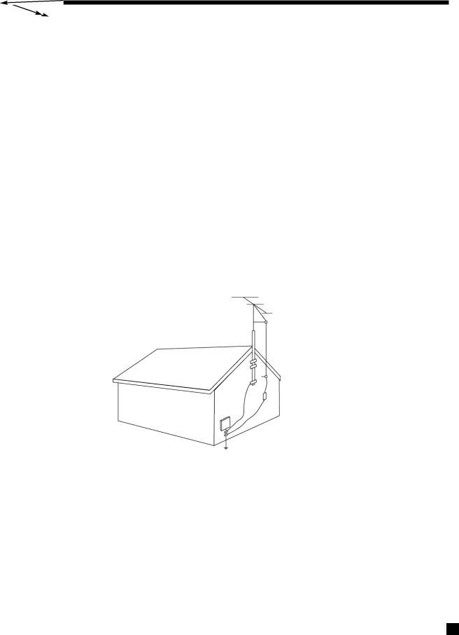
1.3.2OUTDOOR ANTENNA GROUNDING
•If an outside antenna or cable system is connected to the AVM 2, the antenna or cable system must be grounded to provide some protection against voltage surges and built-up static charges. The following diagram contains requirements according to the National Electrical Code:
|
Antenna Lead-In Wire |
Ground Clamp |
Antenna Discharge Unit |
|
|
|
(NEC Section 810-20) |
Electric |
Grounding Conductors |
Service |
|
Equipment |
(NEC Section 810-21) |
|
|
|
Ground Clamps |
|
Power Service Grounding |
|
Electrode System |
NEC: NATIONAL ELECTRICAL CODE |
(NEC Art. 250, Part H) |
1.3.3 MAINS FUSE TYPE
Use a 1.0 Amp 5mm slow blow fuse only. This is not a user serviceable item (see section 1.3.7).
1.3.4 SUPPLY POWER REQUIREMENTS
The AVM 2 can operate from any single phase AC power source that supplies between 105V and 130V at a frequency of 60 Hz.
The AVM 2 uses a polarized power cord with one blade wider than the other so that it only fits into the outlet one way. If the plug cannot be fully inserted with no blade exposed, reverse the plug and try again. If it still does not fit, you have an obsolete outlet – contact an electrician to replace it.
2

1. INTRODUCTION continued …
To prevent risk of shock or fire, do not overload wall outlets, extension cords, or convenience receptacles.
Please note that the power transformer primary cannot be changed from a North American to a European or Asian standard.
1.3.5IN-USE NOTICES
•Use only the power supply cord with double insulation as supplied.
•Disconnect the power cord from the AVM 2 before connecting or disconnecting any components.
•Fuses are not a user serviceable item (see section 1.3.7).
•Do not remove the top cover.
•Do not alter or modify the AVM 2 in any way.
1.3.6CLEANING
Unplug the AVM 2 from the wall outlet before cleaning. A regular dusting with a soft, non-abrasive cloth will generally keep the finish of the faceplate and chassis looking new. Do not allow any liquid to come in contact with the AVM 2; it may run onto the internal electronic circuitry and cause damage that is not covered under warranty.
1.3.7 SERVICING
Do not attempt to open or perform any repairs to the AVM 2. There are no adjustments inside the AVM 2 that can be made by the user, nor are there any user serviceable parts inside. Refer servicing to qualified service personnel only.
1.3.8 NON-USE PERIODS
To prevent damage from power line surges and lightning strikes, unplug the AVM 2 from the power outlet, outside antenna, and cable system when left unused for an extended period of time.
1.4PACKING MATERIALS
Please retain the shipping box and all packing material. They are custom designed to prevent shipping damage from occurring. Do not ship or transport the AVM 2 in anything other than the original box and packing material.
3

2. QUICK START
While the AVM 2 is certainly a massive component with enough features and connections to make your head spin, setup and operation are also very intuitive! With your AVM 2 in front of you, browse through the illustrations in this section showing several quick system hookups. It’s as simple as following the lines in the connection diagrams to and from each component.
All of these quick system hookup examples work with the Factory Default settings; none require the Advanced Setup configuration. Just ‘plug & play’! However, references to the Advanced Setup section are included to make you aware of the tremendous versatility of the AVM 2.
Even though this section makes it easy to get everything hooked up, for the best sound possible you will still have to calibrate your system in the Setup Menu as outlined in Advanced Setup (section 7). Please do not overlook this important system calibration procedure.
2.1QUICK START GUIDE – Before you start, make sure all components are unplugged.
To connect a CD Player, DVD Player, TV, VCR, Amplifier(s), and Powered Subwoofer to the AVM 2:
• CD (Digital) to AVM 2 (see 2.2.1-a)
Connect the CD Player’s Digital Out (RCA-S/PDIF) to the AVM 2’s DISC2 Digital Audio-IN.
• CD (Analog) to AVM 2 (see 2.2.1-b)
Connect CD Player’s L/R Audio Out (RCA) to any analog input you wish. For this example connect to the AVM 2’s AUX L/R Audio-IN.
•DVD Player to AVM 2 (see 2.2.2)
Video: Connect the DVD Player’s Composite Video Out (RCA) to the AVM 2’s DISC1 Composite-IN.
Audio: Connect the DVD Player’s Digital Out (RCA-S/PDIF) to the AVM 2’s DISC1 Digital Audio-IN.
•AVM 2 to TV (see 2.2.2 or 2.2.3)
Video: Connect the AVM 2’s Composite-Out / MAIN (RCA) to the TV’s Composite Video Input.
Audio: Connect the TV’s L/R Audio Out (RCA) to the AVM 2’s TV Analog Audio-IN.
•VCR to AVM 2 (see 2.2.3)
Video: Connect the VCR’s Composite Video Out (RCA) to the AVM 2’s VCR Composite-IN.
To Record: Connect the AVM 2’s Composite-Out / REC (RCA) to the VCR’s Composite Video Input.
Audio: Connect the VCR’s Left/Right Audio Out (RCA) to the AVM 2’s VCR Analog Audio-IN.
To Record: Connect the AVM 2’s L/R Audio Out / REC (RCA) to the VCR’s Analog Audio-IN.
•AVM 2 to Amplifier(s) (see 2.2.4-a or b)
Connect the AVM 2’s Front-L, Front-R, Sur-L, Sur-R and Center (RCA or XLR) Analog Audio-
Out to the Power Amplifier(s)’s Front-L, Front-R, Sur-L, Sur-R and Center Audio Inputs.
Follow amplifier manufacturer’s instructions for connecting speakers.
• AVM 2 to Powered Subwoofer (see 2.2.4-a or b):
Connect the AVM 2’s Sub (RCA) Analog Audio-Out to the Powered Subwoofer’s Line/Low
Level Input (RCA).
Reconnect the power to all components and then turn them on. To turn on the AVM 2 press the POWER – MAIN button on the front panel.
4

2. QUICK START continued …
To Watch a DVD:
•Press DISC1 Source on the front panel of the AVM 2.
•Switch the TV’s Video Input to the one that the AVM 2 Composite-Out is plugged into.
•Place a DVD into the DVD Player and press play. You should see the picture on your TV and hear sound from your speakers. Use the AVM 2 Master Control Knob on the front panel to adjust volume.
To Watch a Video Tape:
•Press VCR Source on the front panel of the AVM 2.
•Switch the TV’s Video Input to the one the AVM 2 composite-out is plugged into.
•Insert a tape into the VCR Player and press play. You should see the picture on your TV and hear sound from your speakers. Use the Master Control Knob on the front panel to adjust volume.
To Listen to a CD:
•Press either the DISC2 Source (Digital-In S/PDIF) or AUX Source (Analog-In Left/Right) on the front panel of the AVM 2.
•Place a CD into the CD Player and press play. You should hear music coming from your speakers. Use the Master Control Knob on the front panel to adjust volume.
Note about Digital and Analog Inputs:
•DISC1, DISC2 and SAT are factory default set for Digital Input, whereas TAPE, TV, VCR, and AUX are factory default set for Analog (Left/Right) Inputs. You can however, change any of these to either Digital or Analog as required. In addition, the Digital Input can also be changed from RCA to Toslink or XLR. To make these changes see section 7.4.2.
Note about On-Screen Display:
•The On-Screen Display is factory default set for Composite-Out. This can be changed to S-Video or turned off. To make these changes see section 7.4.9 menu 9.b.
Note about Your Speakers:
•The AVM 2 allows you to enter information about how many speakers you have in your system, their relative size, and their distance from your listening position. This speaker setup information is important in directing audio signals optimally, ensuring you get the best quality sound from your system. Please see sections 7.4.3, 7.4.4, and 7.4.5.
2.2CONNECTOR DIAGRAMS AND DESCRIPTIONS
The following pages of illustrations contain a variety of standard cable/connectors that are used to connect components to your AVM 2. Here’s what they are, what they look like, and what they are used for:
RCA Black or |
RCA Yellow |
3.5mm |
5-Pin |
XLR Female |
XLR Male |
RCA Red |
1/4” Stereo Plug |
Mono Mini Plug |
Toslink |
||
White |
or Brown |
Mini DIN |
|
|
Analog Left |
Analog Right |
Digital S/PDIF or |
|
|
|
|
Channel |
Channel |
Composite Video |
|
|
|
|
RCA Green - |
RCA Blue - |
RCA Red - |
Relay Trigger |
Digital Audio |
Analog Balanced |
Analog Balanced or |
Component Y |
Component Pb/Cb |
Component Pr/Cr |
Headphone |
S-Video |
or Digital AES/EBU |
Digital AES/EBU |
IR Receiver |
S/PDIF |
|||||
|
|
|
|
|
|
|
5

2. QUICK START continued …
2.2.1-a CD Player or CD Transport to AVM 2 (Digital)
NOTE: XLR or Toslink
Amplifier(s)
use is OPTIONAL (see
sections 4.2.1 and 7.4.2)
2.2.1-b CD Player to AVM 2 (Analog)
Amplifier(s)
6

2. QUICK START continued …
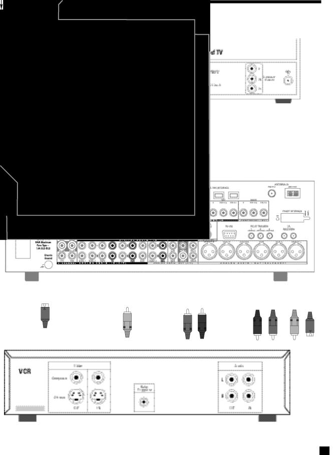
2.2.2DVD Player and TV to AVM 2
|
|
|
NOTE: S-Video or |
|
|
|
|
|
|
|
|
|
|
|
Component Video |
|
|
|
use is OPTIONAL |
|
|
|
|
Amplifier(s) |
|
||
|
(see sections |
||
|
|
|
4.3 and 7.4.9) |
|
|
|
|
NOTE: S-Video or
Component Video
use is OPTIONAL
(see sections
4.3 and 7.4.9)
7
2. QUICK START continued …
2.2.3VCR and TV to AVM 2
NOTE: S-Video use is OPTIONAL (see sections 4.3 and 7.4.9)
Amplifier(s)
NOTE: S-Video
use is OPTIONAL
(see sections
4.3 and 7.4.9)
NOTE: S-Video |
|
use is OPTIONAL |
NOTE: |
(see sections |
Audio/Video |
4.3 and 7.4.9) |
Record Out/In |
|
Connections |
|
are OPTIONAL |
|
|
8
2. QUICK START continued …
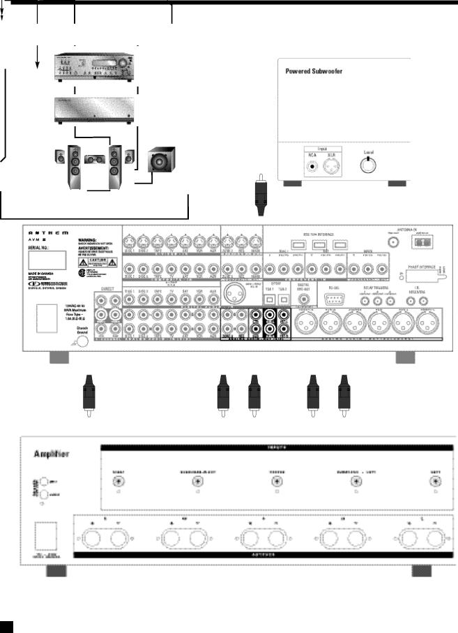
2.2.4-a AVM 2 to Amplifier and Powered Subwoofer (RCA)
Follow amplifier manufacturer’s complete hook-up instructions to
connect amplifier outputs to matching speakers.
9

2. QUICK START continued …
2.2.4-b AVM 2 to Amplifier and Powered Subwoofer (XLR)
Follow amplifier manufacturer’s complete hook-up instructions to
connect amplifier outputs to matching speakers.
10
2. QUICK START continued …
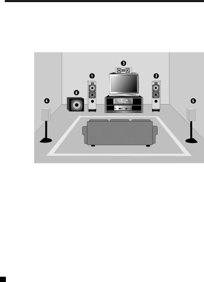
2.3SURROUND SYSTEM SPEAKER PLACEMENT
This illustration shows the typical speaker placement for a 6-channel surround system, also known as a 5.1 channel system, the ‘.1’ channel being the LFE (Low Frequency Effect). The Front-Left, Center, and Front-Right speakers are directed toward the listener from the front while the Left and Right Surround speakers are positioned to the sides or behind the listener.
1.Front-Left Speaker
2.Front-Right Speaker
3.Center Channel Speaker
4.Surround-Left Speaker (Diffuse Type – drivers on both sides with ‘null’ facing the listening area.)
5.Surround-Right Speaker (Diffuse Type – drivers on both sides with ‘null’ facing the listening area.)
6.Subwoofer
For optimal results, the size of the speakers and the distance of each speaker to the listening position should be entered in the Setup Menu of the AVM 2 (see sections 7.4.3, 7.4.4, and 7.4.5 )
11

3. PANELS / DISPLAY/ REMOTE LAYOUT
3.1-a FRONT PANEL LAYOUT
The front panel of the AVM 2 has the MASTER CONTROL KNOB, selection buttons, an LCD display, status indicator LED’s, and the Headphone jack .
1 |
2 |
3 |
4 |
5 |
6 |
 7
7
 8
8
9
20 |
19 |
18 |
17 |
16 |
15 |
14 |
13 |
12 |
11 |
10 |
1 |
– |
Zone / Path Selection |
10 |
– |
Status / Setup Menu (press and hold for 3 seconds) |
|
2 |
– |
Mode / Surround Decoder Indicators |
11 |
– |
Mute |
|
3 |
– |
LCDDisplay |
12 |
– |
Dolby Digital Dynamics Selection |
|
4 |
– |
FM/AM Station Preset Selection |
13 |
– |
Tone Bypass |
|
5 |
– |
FM/AM Tuning / Setup Menu Navigation |
14 |
– |
Balance Selection for Adjustment |
|
6 |
– |
Master Control Knob (Volume, FM/AM Tune, |
15 |
– |
Bass / Treble Selection for Adjustment |
|
|
|
Function Adjustment, Setup Menu Adjustment) |
16 |
– |
Front Panel Remote Control IR Sensor |
|
7 |
– |
Speaker / Headphones Selection for |
||||
17 |
– |
Front Panel Brightness Selection |
||||
|
|
Level / Bass / Treble / Balance Adjustments |
||||
|
|
18 |
– |
Dolby Pro-Logic / Effects / 96 kHz Stereo Selection |
||
8 |
– |
Subwoofer Level / LFE Level Selection |
||||
19 |
– Headphone Jack |
|||||
|
|
for Adjustment |
||||
|
|
20 |
– |
Source Selection (Direct – press twice) |
||
9 |
– |
Power On / Stand-By Selection (MAIN / ZONE2) |
||||
|
|
|
||||
• See section 5 for complete information on Front Panel Operation.
12

3. PANELS / DISPLAY/ REMOTE LAYOUT continued …
3.1-b FRONT PANEL LCD DISPLAY
Here are two examples of the Front Panel LCD Display presentations:
MAIN Display
1 |
2 |
3 |
5 |
4 |
1– Source Selection (see section 5.5).
2– Audio-In Format (see section 7.4.2) or Sleep Indicator if engaged (see section 6.6).
3– Zone / Path that the information on the display refers to (see sections 5.1, 5.3).
4– Volume Setting. When MAIN or ZONE2 are muted, “Muted” flashes instead of the current volume setting (see section 5.8).
5– Mode / Effects (if the source is FM/AM, then the tuned station appears).
FM/AM Display
1 |
2 |
3 |
3 |
|
|
|
|
|
|
|
|
5 |
4 |
1– Source+Band. The tuner has three FM bands (FM1, FM2, and FM3) and one AM band. The number after the selected band is the preset station (see section 5.5.4).
2– Mode for FM. Displays “St” when in stereo, “HB” when Hi-Blend is selected, or “Mn” when in mono or mono is selected (see section 5.5.4).
3– Seek when tuning FM/AM stations (see section 5.5.4).
4– Zone / Path (see sections 5.1, 5.3).
5– Volume Setting. When MAIN or ZONE2 are muted, “Muted” flashes instead of the current volume setting (see section 5.8).
6– Currently tuned FM/AM frequency to the nearest 0.1 MHz for FM and to nearest 10 kHz for AM (see section 5.5.4).
13
3. PANELS / DISPLAY/ REMOTE LAYOUT continued …
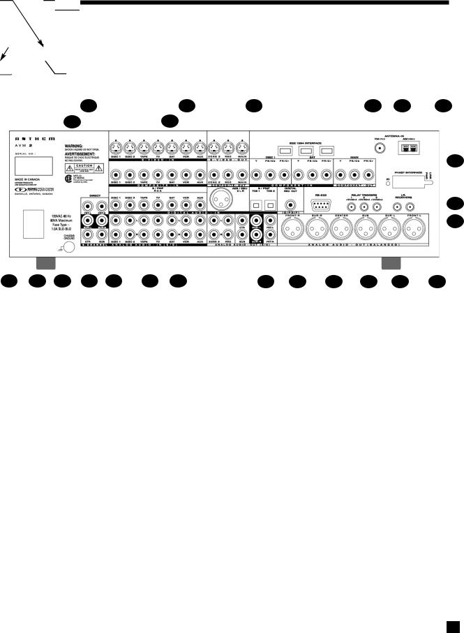
3.2REAR PANEL LAYOUT
The Rear Panel of the AVM 2 contains all connections, such as the Audio and Video Inputs and Outputs, the FM/AM Antenna Inputs, AC Power connection and the RS-232 port which allows upgrading of the internal operating Software as well as control of the AVM 2 by external devices.
2 |
4 |
5 |
7 |
8 |
1 |
3 |
|
|
|
9
 10
10
11
24 |
23 |
22 |
21 |
20 |
19 |
18 |
17 |
16 |
15 |
14 |
13 |
12 |
1 |
– 7 Composite Video RCAInputs |
13 |
– |
RS-232 Interface Port (Bi-Directional) |
2 |
– 7 S-Video Inputs |
14 |
– |
Digital Audio RCA S/PDIF Record Output |
3 |
– 3 Composite Video RCA Outputs |
15 |
– |
2 Digital Audio Toslink Inputs (Assignable) |
4 |
– 3 S-Video Outputs |
16 |
– |
MAIN Analog Audio RCA Output (6 Jacks) |
5 |
– 3 IEEE 1394 Interface Port provisions* |
17 |
– |
REC Analog Audio Stereo RCA Output (L/R Jacks) |
6 |
– 2 Component Video RCAInputs (3 Jacks/ea) |
18 |
– |
ZONE2 Analog Audio Stereo RCA Output (L/R Jacks) |
7 |
– Component Video RCA Output (3 Jacks) |
19 |
– |
Digital Audio AES / EBU Input (Assignable) |
8 |
– FM and AM Antenna Inputs |
20 |
– |
7 Analog Audio Stereo RCA Inputs (L/R Jacks) |
9 |
– PHASTLINK RJ45 Interface Port provision* |
21 |
– |
7 Digital Audio RCA S/PDIF Inputs |
10 |
– 2 Infra Red (IR) 3.5mmInputs |
22 |
– |
Analog Audio 6-Channel Direct RCA Input (6 Jacks) |
11 |
– 3 Relay Trigger 3.5mm Outputs (Assignable) |
23 |
– |
Ground Terminal |
12 |
– MAIN Analog Audio Balanced XLR Output (6 Jacks) |
24 |
– |
Power Cord Connection |
•See section 4 for complete information on Rear Panel Connections.
*Interface card requires installation by a qualified dealer.
14
3. PANELS / DISPLAY/ REMOTE LAYOUT continued …
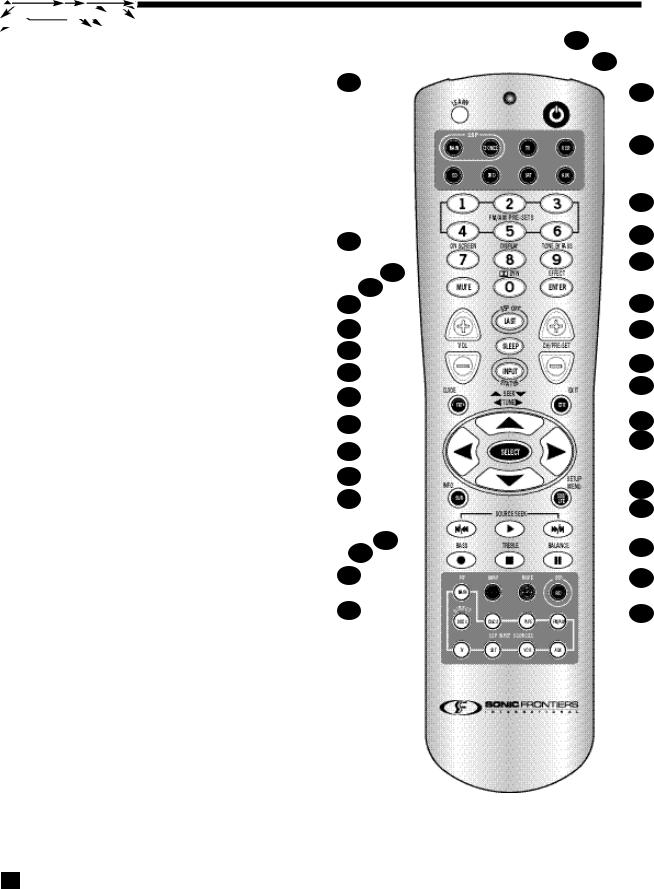
3.3REMOTE CONTROL LAYOUT
1 – IR Transmitter (front face) |
35 |
2– Transmission Indicator LED (red)
3– AVM 2 Power ON when MAIN or ZONE2 is selected Power ON/OFF for other components (see #4)
Note: This does not turn the AVM 2 off (see #31)
4– Zone/Path/Component ‘Personality’ Selection
5– FM/AM Station Preset Selection (6)
6– Tone Bypass Selection
7– Dolby Pro-Logic / Effects / 96 kHz Stereo Selection
8 |
– |
Dolby Digital Dynamics Selection |
34 |
|
|
||||
9 |
– |
FM/AM Pre-set Station Up |
33 |
|
10 |
– |
FM/AM Pre-set Station Down |
32 |
|
11 |
– |
Status |
31 |
|
|
||||
12 |
– |
Center Channel Selection for Adjustment |
30 |
|
13 |
– |
Back / Exit for Setup Menu |
29 |
|
14 |
– |
Subwoofer Level / LFE Level Selection |
28 |
|
|
|
for Adjustment |
27 |
|
15 |
– |
Setup Menu (Press & Hold for 3 seconds) |
||
|
||||
16 |
– |
Source Seek |
26 |
|
17 |
– |
Balance Selection for Adjustment |
25 |
|
18 |
– |
REC Path Selection (Must be in MAIN – see #4) |
||
24 |
||||
19 |
– |
Source Selection 8 Keys – 9 inputs (Direct – press twice) |
||
23 |
||||
|
|
|
20– MAIN Source copy to ZONE2 or REC
21– Bass Selection for Adjustment
22
22 – Treble Selection for Adjustment
21
23 – Surround Channels Selection for Adjustment
20
24 –  FM/AM Seek / Setup Menu Navigation /
Bass/Treble Adjustment
19
25 – 34FM/AM Tune / Setup Menu Navigation / Balance Adjustment
26 – Select Function in Setup Menu
27 – Front Channels / Headphones Selection for Adjustments
28 – Volume Down
29 – Sleep Timer Selection
30 – Volume Up
31 – AVM 2 Power OFF when MAIN or ZONE2 is selected
32 – Mute
33 – Front Panel / LCD Display Brightness Selection
34 – On-Screen
35 – Learn (for customization of remote)
• See section 6 for complete information on operation of the Remote Control.
1
2
3
4
5
6
7
8
9
 10
10
11
12
13
14
15
16
17
18
15
4. CONNECTIONS
4.1CONNECTING POWER TO THE AVM 2
Connect the power cord to the back of the AVM 2 and then to an AC outlet with a line voltage of between 105 and 130 Volts, 60 Hz.
When turned on, the AVM 2 will have all of the same settings it had when it was last turned off, except for Volume, which comes on at the pre-programmed setting (see section 7.4.6).
4.2AUDIO CONNECTIONS
There are two methods of transmitting audio signals: Analog and Digital. Analog is an electrical waveform representation of sound and requires one cable for each channel. Digital represents sound using a sequence of numbers and requires only one cable for all channels. We recommend using digital connections wherever possible because they have lower background noise and provide better quality than analog connections when both formats are available. Connecting a DVD player or CD player to both the digital and analog connectors allows listening to an analog source in ZONE2 and REC, while listening to a digital source in MAIN.
The AVM 2 accepts either analog or digital audio signals in all inputs except DIRECT, which accepts analog audio signals only. From the factory, DISC1, DISC2 and SAT inputs are set to Digital, whereas the TAPE, TV, VCR, and AUX inputs are set to Analog. Every audio input, except DIRECT, can be changed from the factory setting to either Digital or Analog (see section 7.4.2).
4.2.1 DIGITAL AUDIO INPUTS / DIGITAL AUDIO OUTPUT
Digital Audio input connections are made through a 75-ohm coaxial (RCA), optical (TOS), or 110-ohm balanced (XLR) cable. DVD Players and CD Transports are generally connected using a coaxial cable with RCA connectors.
Note: The DIGITAL REC OUT (RCA-S/PDIF) only functions with Digital Audio Input Sources (e.g. DISC1, DISC2, or any other input source that you have set to ‘digital’, see section 7.4.2).
Note: This is also part of the independent REC Path (see Section 5.3).
4.2.2 ANALOG AUDIO INPUTS
Analog audio connections are made with RCA interconnect cables. Note: REC and ZONE2 require analog audio connection unless set to ‘copy’ MAIN (see section 5.5.1).
|
From DVD Player |
|
From DVD Player |
|
From Tape |
|
From TV |
|
|||||
|
6-Channel |
|
Audio OUT |
|
Audio OUT |
|
Audio OUT |
|
|||||
|
Audio OUT |
|
|
|
|
|
|
|
|
|
|
|
|
|
|
|
|
|
|
|
|
|
|
|
|||
|
|
|
|
From CD Player |
|
|
|
From Satellite Receiver |
|
|
|||
|
|
|
|
|
|
|
|
|
|||||
|
|
|
|
Audio OUT |
|
|
|
|
Audio OUT |
|
|||
Caution for DTS: |
|
|
|
|
|
|
|
|
|
|
|
||
|
|
|
|
|
|
|
|
|
|
|
|||
|
|
|
|
|
|
|
|
From VCR |
|
||||
With DTS-CD’s or DTS Laser Disks, |
|
|
|
|
|
|
|
|
Audio OUT |
|
|||
do not use analog connection if your |
|
|
|
|
|
|
|
|
|
|
|
||
|
|
|
|
|
|
|
|
|
|
|
|||
Player does not have an internal DTS |
|
|
|
|
|
|
|
|
|
|
|
||
decoder, because a loud noise is |
|
|
|
|
|
|
|
|
|
|
|
||
produced at the analog outputs of |
|
|
|
|
|
|
|
|
|
|
|
||
the Player. Players with an internal |
|
|
|
|
|
|
|
|
|
|
|
||
DTS decoder may require a change |
|
|
|
|
|
|
|
|
|
|
|
||
in their setup menu to enable DTS |
|
|
|
|
|
|
|
|
From Auxiliary |
||||
decoding (see Player owner’s manual). |
|
|
|
|
|
|
|
|
|||||
|
|
|
|
|
|
|
|
|
|
|
|
Audio OUT |
|
16
 Loading...