


MRX520
A / V R E C E I V E R
OPERATING MANUAL
I M P O R T A N T S A F E T Y I N S T R U C T I O N S
CAUTION
RISK OF ELECTRIC SHOCK DO NOT OPEN
CAUTION: TO REDUCE THE RISK OF ELECTRIC SHOCK, DO NOT REMOVE COVER (OR BACK). NO USER-SERVICEABLE PARTS INSIDE. REFER SERVICING TO QUALIFIED SERVICE PERSONNEL
The lightning flash with arrowhead symbol within an equilateral triangle is intended to alert the user to the presence of uninsulated “dangerous voltage” within the product’s enclosure that may be of sufficient magnitude to constitute a risk of electric shock to persons.
The exclamation point within an equilateral triangle is intended to alert the user to the presence of important operating and maintenance (servicing) instructions in the literature accompanying the appliance.
1.Read these instructions.
2.Keep these instructions.
3.Heed all warnings.
4.Follow all instructions.
5.Do not use this apparatus near water.
6.Clean only with a dry cloth.
7.Do not block any of the ventilation openings. Install in accordance with the manufacturer’s instructions.
8.Do not install near any heat sources such as radiators, heat registers, stoves or other apparatus (including amplifiers) that produce heat.
9.Do not defeat the safety purpose of the polarized or grounding-type plug. A polarized plug has two blades with one wider than the other. A grounding-type plug has two blades and a third grounding prong. The wide blade or the third prong is provided for your safety. When the provided plug does not fit into your outlet, consult an electrician for replacement of the obsolete outlet.
10.Protect the power cord from being walked on or pinched, particularly at plugs, convenience receptacles and the point where they exit from the apparatus.
11.Only use the attachments/accessories specified by the manufacturer.
12.Use only with a cart, stand, tripod, bracket or table specified by the manufacturer, or sold with the apparatus. When a cart is used, use caution when moving the cart/apparatus combination to avoid injury from tip-over.
13.Unplug this apparatus during lightning storms or when unused for long periods of time.
14.Refer all servicing to qualified service personnel. Servicing is required when the apparatus has been damaged in any way, such as power supply cord or plug is damaged, liquid has been spilled or objects have fallen into the apparatus, the apparatus has been exposed to rain or moisture, does not operate normally, or has been dropped.
I

WARNING: To reduce the risk of fire or electric shock, do not expose this apparatus to rain or moisture. Avoid installing this unit where foreign objects may fall onto this unit and/or this unit may be exposed to liquid dripping or splashing. On the top of this unit, do not place:
•Burning objects (i.e. candles), as they may cause fire, damage to this unit, and/or personal injury.
•Containers with liquid in them, as they may fall and liquid may cause electrical shock to the user and/or damage to this unit.
Apparatus shall not be exposed to dripping or splashing and no objects filled with liquids, such as vases, shall be placed on the apparatus.
Do not install this equipment in a confined space such as a case or similar. Install it away from direct sunlight, heat sources, vibration, dust, moisture, and/or cold.
Do not cover this unit with a newspaper, tablecloth, curtain, etc. in order not to obstruct heat radiation. If the temperature inside this unit rises, it may cause fire, damage to this unit, and/or personal injury.
Install this unit near the AC outlet and where the AC power plug can be reached easily.
This unit is not disconnected from the AC power source when it is turned off. This state is called the standby mode. In this state, this unit is designed to consume a very small quantity of power. To completely disconnect this apparatus from the AC mains, disconnect the power supply cord plug from the AC receptacle.
NOTE: This product is not an auto voltage Receiver. Connect only to the prescribed AC outlet, i.e., 120V 60Hz or 220-240V 50Hz.
CAUTION: These servicing instructions are for use by qualified service personnel only. To reduce the risk of electric shock, do not perform any servicing other than that contained in the operating instructions, unless you are qualified to do so.
CAUTION: Changes or modifications to this equipment not expressly approved by Paradigm Electronics for compliance could void the user’s authority to operate this equipment.
FCC WARNING: Changes or modifications not expressly approved by the party responsible for compliance could void the user’s authority to operate the equipment.
This equipment has been tested and found to comply with the limits for a class B digital device, pursuant to part 15 of the FCC Rules. These limits are designed to provide reasonable protection against harmful interference in a residential installation. This equipment generates, uses and can radiate radio frequency energy and, if not installed and used in accordance with the instructions, may cause harmful interference to radio communications. However, there is no guarantee
that interference will not occur in a particular installation. If this equipment does cause harmful interference to radio or television reception, which can be determined by turning the equipment off and on, the user is encouraged to try to correct the interference by one or more of the following measures:
•Reorient or relocate the receiving antenna.
•Increase the separation between the equipment and the unit.
•Connect the equipment into an outlet on a circuit different from that to which the unit is connected.
•Consult the dealer or an experienced radio / TV technician for help.
II

DO NOT LOCATE IN THE FOLLOWING PLACES:
To ensure long-lasting use, do not locate the unit:
• |
Exposed to direct sunlight. |
Left 0.2 m (8 in) |
Above 0.2 m |
Right 0.2 m |
• Near sources of heat such as heaters. |
or more |
(8 in) or more |
(8 in) or more |
|
|
|
|
||
• |
Highly humid or poorly ventilated. |
|
|
|
•Dusty.
•Subjected to mechanical vibrations.
• On wobbly, inclined, or otherwise unstable surfaces.
• Near windows where there is a chance of exposure |
|
|
|
|
Behind 0.2 m (8 in) or more |
||||
to rain, etc. |
||||
|
|
|
||
•On top of an amplifier or other component which dissipates a great deal of heat.
To ensure proper heat radiation, ensure clearance from walls and other equipment according to diagram.
IMPORTANT INFORMATION FOR UK CUSTOMERS: DO NOT cut off the mains plug from this equipment. If the plug fitted is not suitable for the power points in your home or the cable is too short to reach a power point, then obtain an
appropriate safety approved extension lead or consult your dealer. If, nonetheless, the mains plug is cut off, REMOVE THE FUSE and dispose of the PLUG immediately, to avoid possible shock hazard by inadvertent connection to the mains supply. If this product is not provided with a mains plug, or one has to be fitted, then follow the instructions given below:
IMPORTANT: DO NOT make any connection to the larger terminal which is marked with the letter “E” or by the safety earth symbol or colored GREEN or GREEN AND YELLOW.
The wires in the mains lead on this product are colored in accordance with the following code:
BLUE – NEUTRAL BROWN – LIVE
As these colors may not correspond with the colored markings identifying the terminals in your plug, proceed as follows:
The BLUE wire must be connected to the terminal marked with the letter “N” or colored BLACK.
The BROWN wire must be connected to the terminal marked with the letter “L” or colored RED.
When replacing the fuse, only a correctly rated and approved type should be used, and be sure to re-fit the fuse cover. If in doubt consult a competent electrician.
III

NOTES ON ENVIRONMENTAL PROTECTION
At the end of its useful life, this product must not be disposed of with regular household waste but must be returned to a collection point for the recycling of electrical and electronic equipment. The symbol on the product, user’s manual and packaging, point this out. The materials can be reused in accordance with their markings. Through re-use, recycling of raw materials or other forms of recycling of old products, you are making
an important contribution to the protection of our environment. Your local administrative office can advise you of the responsible waste disposal point.
INFORMATION ABOUT COLLECTION AND DISPOSAL OF WASTE BATTERIES (DIRECTIVE 2006/66/EC OF THE EUROPEAN PARLIAMENT AND THE COUNCIL OF EUROPEAN UNION) (for European customers only)
Batteries bearing any of these symbols indicate that they should be treated as “separate collection” and not as municipal waste. It is encouraged that necessary measures are implemented to maximize the separate collection of waste batteries and to minimize the disposal of batteries as mixed municipal waste. End-users are exhorted not to dispose waste batteries as unsorted municipal waste. In order to achieve a high level of recycling waste batteries, discard waste batteries separately and properly through an accessible collection point in your vicinity. For more information about collection and recycling of waste batteries, please contact your local municipality, your waste disposal service or the point of sale where you purchased the items.
By ensuring compliance and conformance to proper disposal of waste batteries, potential hazardous effects on human health is prevented and the negative impact of batteries and waste batteries on the environment is minimized, thus contributing to the protection, preservation and quality improvement of the environment.
|
|
|
|
|
|
|
|
|
Pb |
|
Hg |
|
Cd |
Anthem and any related party assume no liability for the user’s failure to comply with any requirements.
Anthem, AnthemLogic, ARC, Sonic Frontiers, and Paradigm are trademarks or registered trademarks of Paradigm Electronics Inc. © Paradigm Electronics Inc. All rights reserved. The information contained herein may not be reproduced in whole or in part without our express written permission. We reserve the right to change specifications
or features without notice as design improvements are incorporated.
Manufactured under license from Dolby Laboratories. Dolby, Dolby Atmos, Pro Logic, and the double-D symbol are trademarks of Dolby Laboratories.
For DTS patents, see http://patents.dts.com. Manufactured under license from DTS Licensing Limited. DTS, Play-Fi, the Symbol, DTS in combination with the Symbol, Play-Fi in combination with the Symbol, DTS:X, and the DTS logo are registered trademarks or trademarks of DTS, Inc. in the United States and/or other countries. © DTS, Inc. All Rights Reserved
HDMI, the HDMI logo and High-Definition Multimedia Interface are trademarks or registered trademarks of HDMI Licensing LLC.
All other trademarks are the property of their respective owners.
IV

T A B L E O F C O N T E N T S
INTRODUCTION |
ANTHEM ROOM CORRECTION |
|||||
1 |
1.1 |
Before Making Connections |
29 |
4.1 |
Before Starting |
|
1 |
1.2 |
In-Use Notices |
29 |
4.2 |
ARC Software Installation |
|
2 |
1.3 |
Front Panel |
30 |
4.3 |
Microphone Stand Assembly |
|
3 |
1.4 |
Rear Panel |
30 |
4.4 |
Microphone Positioning |
|
4 |
1.5 |
Remote Control |
30 |
4.5 |
Measurement |
|
5 |
1.6 |
Speaker Positioning |
32 |
4.6 |
Manual Mode and Targets |
|
|
|
|
33 |
4.7 |
Advanced Subwoofer Targets |
|
CONNECTIONS |
34 |
4.8 |
Printing A Report |
|||
|
|
|
||||
6 |
2.1 |
Video Input and Output |
OPERATION |
|||
7 |
2.2 |
Audio Connections |
||||
|
|
|
||||
10 |
2.3 |
Antenna |
35 |
5.1 |
Power On / Off and Volume |
|
10 |
2.4 |
Local Area Network |
35 |
5.2 |
Zone 2 Operation |
|
10 |
2.5 |
12 Volt Trigger |
36 |
5.3 |
Input Selection |
|
10 |
2.6 |
Infra Red |
36 |
5.4 |
Tuner |
|
10 |
2.7 |
Power |
37 |
5.5 |
Level Trim |
|
|
|
|
38 |
5.6 |
Bass / Treble / Balance |
|
SETUP |
|
38 |
5.7 |
Lip-Sync |
||
|
38 |
5.8 |
Listening Modes |
|||
|
|
|
||||
13 |
3.1 |
Speaker Setup |
39 |
5.9 |
Dolby Volume and Dynamic Range Control |
|
14 |
3.2 |
Bass Managment |
39 |
5.10 Display Brightness |
||
15 |
3.3 |
Listener Position |
39 |
5.11 Info Display |
||
16 |
3.4 |
Level Calibration |
|
|
|
|
17 |
3.5 |
Input Setup |
40 |
LIMITED WARRANTY |
||
20 |
3.6 |
Preferences / Line Output |
||||
|
|
|
||||
22 |
3.7 |
Network / Remote Control |
|
|
|
|
24 |
3.8 |
General Configuration |
|
|
|
|
263.9 Save / Load Settings
273.10 System Information
V

I N T R O D U C T I O N
1.1 BEFORE MAKING CONNECTIONS
Check that you have received all items listed below and report discrepancies to your dealer as soon as possible. In case the unit needs to be transported in the future, keep the packing materials. Retain the invoice that you received from your authorized Anthem dealer at time of purchase – without it, service will not be provided under warranty.
•AVM Processor or MRX Receiver
•Remote control
•FM antenna
•Wireless network antennas (2)
•2 AAA batteries
•IEC power cord (US / UK / EU / CN types are supplied by factory, other types are normally provided by the local distributor)
Additional items in Anthem Room Correction kit (ARC):
•USB Microphone
•Microphone clip
•Telescopic stand with boom
•USB cable
•CAT5 cable
1.2 IN-USE NOTICES
•Disconnect the power cord before connecting or disconnecting any components.
•If the receiver was transported or stored in the cold, let it reach room temperature before use.
•Due to continuing advances, operational characteristics may change. If this manual contains discrepancies please check www.anthemAV.com for the latest manual or software.
1

1.3 |
FRONT PANEL |
|
|
|
|
|
|
|
|
|
1 |
|
2 |
|
|
|
|
|
3 |
|
12 |
11 |
10 |
9 |
8 |
7 |
6 |
5 |
4 |
1– Navigation buttons
2– Display
3– Volume, level functions, and character selection
4– Power / standby
5– Input selection
6– Zone 2 selection
7– Level selection
8– Remote control sensor location
9– Mode selection
10– Display brightness
11– Setup menu selection
12– (Behind Cover) Headphone jack, HDMI/MHL jack, USB jack for software updates
2

1
15
1.4 REAR PANEL
US model shown. EU model is similar.
2 |
3 |
4 |
Manufactured under license from Dolby Laboratories. Dolby, Pro Logic, and the double-D symbol are trademarks of Dolby Laboratories.
14 |
13 |
12 11 |
10 |
9 |
8 |
7 |
6 |
5 |
1– FM antenna connections
2– HDMI inputs - HDMI7 supports MHL
3– HDMI outputs - HDMI1 supports Audio Return Channel
4– Local area network connection for IP control and Anthem Room Correction
5– AC input
6– RS-232 interface (bidirectional) for serial control
7– IR input and trigger output
8– Coaxial digital audio inputs
9– Optical digital audio inputs and output
10– Speaker connections
11– Zone 2 audio output
12– Line audio output
13– Analog audio inputs
14– Main pre-out connections
15– Chassis ground screw
3

1.5 REMOTE CONTROL
1 – Main zone power on and standby
2 – Bass, Treble, Balance, Channel Level, Front panel dimmer
3 – Numeric keypad for tuner presets
4 – Input list
5 – Tuner preset
6 – Setup menu
7 – Info and status
8 – Navigation controls
9 – Clear for deleting input configurations and tuner presets, and clearing new entry
10 – Dolby Volume and Dolby Digital Dynamics
11 – Listening mode
12 – Volume
13 – Last menu entry and Home Button for MHL Sources 14 – Mute
15 – Next/previous tuner preset, setup menu page up/down
16 – Lip-sync
17 – Backlight
18 – Zone 2 controls
The left/right buttons also select previous/next input. The up/down buttons also control tuner station.
1
2
|
BASS |
|
DIM |
BAL |
|
3 |
TREB |
|
|
LEVEL |
|
4 |
1 |
|
2 |
3 |
|
|
|
|
|||
5 |
4 |
|
5 |
6 |
|
7 |
|
8 |
9 |
|
|
|
|
|
|||
|
PRESET |
|
0 |
INPUT |
|
6 |
SETUP |
|
|
i |
|
|
|
|
|
||
|
|
|
|
|
|
7 |
|
SELECT |
|
|
|
|
|
|
|
||
8 |
|
|
|
|
|
9 |
CLEAR |
DYN |
|
LAST |
|
|
MO |
|
13 |
||
|
|
DE |
|
||
|
|
|
|
|
|
10 |
|
|
|
|
|
11 |
VOL |
LIP-SYNC |
PG/PR |
14 |
|
|
|
|
|
||
12 |
|
|
|
|
15 |
|
|
ZONE 2 |
|
16 |
|
|
VOL |
|
|
PR |
17 |
|
|
|
|
||
|
VOL |
|
INPUT |
PR |
|
18
RC-MRX 2
4
1.6 SPEAKER POSITIONING
This illustration shows typical speaker placement.
5.1
Channel
5

C O N N E C T I O N S
This section describes connections between system components. Configuration of input and output will be discussed later, in section 3.
2.1 VIDEO INPUT AND OUTPUT
With HDMI connection, video and audio are carried together. Connect HDMI output from MRX to a display with HDMI input – one with the appropriate version of Highbandwidth Digital Content Protection (HDCP) is required to display copy-protected material.
HDMI input 7 is also an MHL input (Mobile High-definition Link). Use this input if the source component also supports MHL, for example smaller media players that receive power through this interface.
Insert HDMI cables gently because the connector is more delicate than traditional ones. Damaged cables can damage jacks, and replacement jacks are not covered by warranty therefore replacing HDMI cables is recommended if there is any chance that the existing ones have been used improperly.
Use only certified High Speed cables and connecting devices. Cables and connecting devices that worked in an older setup do not necessarily work with newer video formats such as Deep Color, UHD, or high frame rates. If you are using adapters or port savers, start troubleshooting by eliminating them since they can affect bandwidth.
6
2.2 AUDIO CONNECTIONS
AUDIO INPUTS AND OUTPUTS
Digital audio sources can be connected using an HDMI, coaxial or optical cable. These connections carry linear PCM, Dolby Digital, and DTS audio formats. HDMI connection is generally preferred to ensure that lossless audio is used where sources provide it although optical/coax can also be used for sources outputting 2-channel PCM, Dolby Digital 5.1, and DTS 5.1 without affecting audio quality.
Audio on the HDMI outputs is 2-channel PCM as this is meant for the TV’s use.
HDMI AUDIO RETURN CHANNEL
If the TV provides audio through HDMI ARC, for example when it accesses streaming media sources, it can send the audio to the MRX through HDMI output 1, eliminating the need for a separate audio connection. CEC control, described in a later section, must be enabled for Audio Return Channel to function.
If the display reads “Dial Norm Offset -4.0 dB” at the start of a movie, it is indicating that the encoded level is higher than standard by 4.0 dB – the playback level of all channels is then automatically reduced by 4 dB.
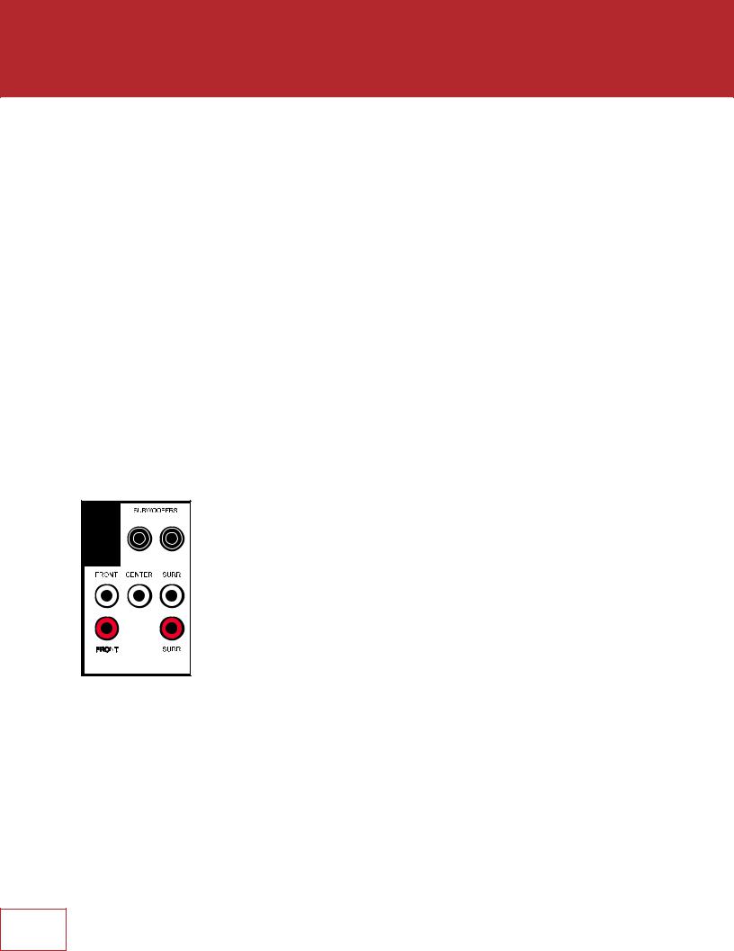
PREAMP OUTPUTS
The pre-outs are variable according to the volume control and can be used with external amplification.
7
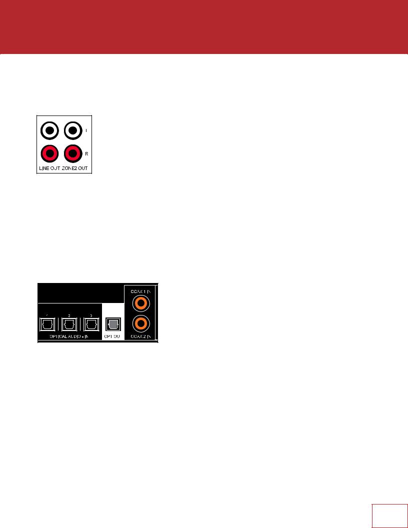
LINE OUTPUT AND ZONE 2 OUTPUT
Line output is a 2-channel version of the selected input with fixed output level. This can be used with a headphone amp which has its own volume control.
Zone 2 has its own volume control and can be used two ways:
-For independent source selection, connect the source using analog input, or optical/ coaxial input as long as the source is 2-channel PCM. This connection can be used in conjunction with HDMI connection for the main zone.
-For similar operation as Line Output but with volume control, set Follow Main to Always in the setup menu (setup is explained later).
OPTICAL AND COAXIAL DIGITAL AUDIO
If HDMI audio from a Dolby Digital, DTS, or 2-channel PCM source is problematic or takes too long to switch, use of coax/optical audio connection is recommended (HDMI video can still be used). Older cable and satellite receivers often benefit from this.
The optical output provides a passthrough of coax/ optical input.
8
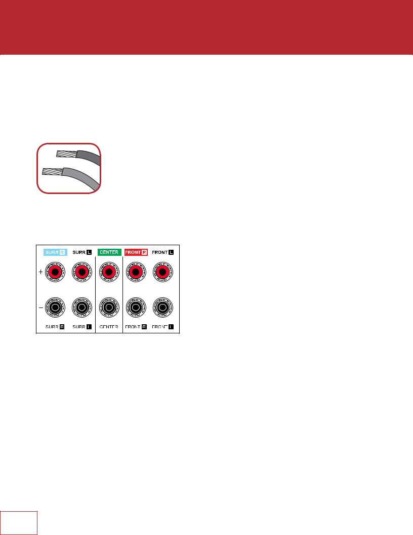
SPEAKER CONNECTIONS
Using speaker wire, connect the positive (+) connection on the speaker to the positive
(+) binding post on the appropriate amplifier output, and the negative (–) connection on the speaker to the negative (–) binding post on the same amplifier channel using cable that is insulated to handle the maximum output of the amplifier. Carefully remove insulation using a wire stripper.
Do not connect more than one speaker to each amplifier output. Be sure that power is turned off when connecting or disconnecting anything, and that the speakers are rated for use with this receiver.
US models allow banana connectors. If using them, first turn the binding post until it is closed to allow the plug to be fully inserted.
If using speaker cables with banana connectors, first turn the binding post until it is closed. This way, the plug can be fully inserted.
9
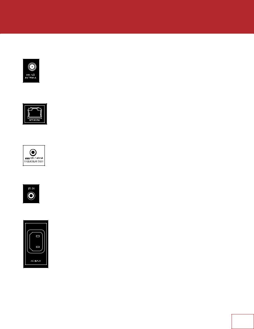
2.3 ANTENNA
Connect the FM antenna to the FM ANTENNA connector.
Later, when unit is operating move the antenna to find best reception.
2.4LOCAL AREA NETWORK
A network connection is required for configuring Anthem Room Correction, using the Play-Fi App, or using IP control. To use a wired connection, simply connect your router using CAT5 cable.
2.512 VOLT TRIGGER
If another system component has a trigger input it can be activated by the receiver. Connect the receiver’s trigger output using a cable with 3.5mm mini plugs. The receiver provides flexible trigger options. Through the setup menu, you can specify the conditions for enabling triggers.
2.6INFRA RED
An external IR receiver allows the remote control to be used from another location in your home – connect the receiver from an external IR hub to the IR IN jack. Most standard IR repeater kits can be used but to avoid problems test compatibility before installing permanently.
2.7 |
POWER |
Connect the power cord to the receiver and the power source.
10
 Loading...