


AVM 50v
Table of contents
 Loading...
AVM 50v
OPERATING MANUAL
UPDATES: www.anthemAV.com
S O F T W A R E V E R S I O N 3 . 0 x
™
SAFETY PRECAUTIONS
READ THIS SECTION CAREFULLY BEFORE PROCEEDING!
The lightning flash with arrowpoint within an equilateral triangle
warns of the presence of uninsulated “dangerous voltage”
within the product’s enclosure that may be of sufficient
magnitude to constitute a risk of electric shock to persons.
The exclamation point within an equilateral triangle warns users
of the presence of important operating and maintenance
(servicing) instructions in theliterature accompanyingthe appliance.
WARNING: TO REDUCE THE RISK OF FIRE OR ELECTRIC SHOCK, DO NOT EXPOSE THIS PRODUCT TO RAIN OR MOISTURE
AND OBJECTS FILLED WITH LIQUIDS, SUCH AS VASES, SHOULD NOT BE PLACED ON THIS PRODUCT.
CAUTION: TO PREVENT ELECTRIC SHOCK, MATCH WIDE BLADE OF PLUG TO WIDE SLOT, FULLY INSERT.
CAUTION: FOR CONTINUED PROTECTION AGAINST RISK OF FIRE, REPLACE THE FUSE ONLY WITH THE SAME AMPERAGE
AND VOLTAGE TYPE. REFER REPLACEMENT TO QUALIFIED SERVICE PERSONNEL.
WARNING: UNIT MAY BECOME HOT. ALWAYS PROVIDE ADEQUATE VENTILATION TO ALLOW FOR COOLING. DO NOT
PLACE NEAR A HEAT SOURCE, OR IN SPACES THAT CAN RESTRICT VENTILATION.
IMPORTANT SAFETY INSTRUCTIONS
WARNING: TO REDUCE THE RISK OF ELECTRIC
SHOCK, DO NOT REMOVE COVER (OR BACK).
NO USER-SERVICEABLE PARTS INSIDE. REFER
SERVICING TO QUALIFIED SERVICE PERSONNEL.
RISK OF ELECTRIC SHOCK
DO NOT OPEN
WARNING
1. Read Instructions – All the safety and operating instructions should be read before the product is operated.
2. Retain Instructions – The safety and operating instructions should be retained for future reference.
3. Heed Warnings – All warnings on the product and in the operating instructions should be adhered to.
4. Follow Instructions – All operating and use instructions should be followed.
5. Cleaning – Unplug this product from the wall outlet before cleaning. Do not use liquid cleaners or aerosol cleaners. Use
a damp, soft cloth for cleaning.
6. Water and Moisture – Do not use this product near water – for example, near a bath tub, wash bowl, kitchen sink, or
laundry tub; in a wet basement; or near a swimming pool; and the like.
7. Accessories – Do not place this product on an unstable cart, stand, tripod, bracket, or table. The product may fall,
causing serious injury to a child or adult, and serious damage to the product. Use only with a cart, stand, tripod, bracket,
or table recommended by the manufacturer, or sold with the product. Any mounting of the product should follow
manufacturer’s instructions, and should use a mounting accessory recommended by the manufacturer.
8. Ventilation – Slots and openings in the cabinet are provided for ventilation and to ensure reliable operation of the
product and to protect it from overheating, and these openings must not be blocked or covered. The openings should
never be blocked by placing the product on a bed, sofa, rug, or other similar surface. This product should not be placed
in a built-in installation such as a bookcase or rack unless proper ventilation is provided or the manufacturer’s
instructions have been adhered to.
9. Power Sources – This product should be operated only from the type of power source indicated on the marking label.
If you are not sure of the type of power supply to your home, consult your product dealer or local power company. For
products intended to operate from battery power, or other sources, refer to the operating instructions.
10. Grounding and Polarization – This product may be equipped with a polarized alternating-current line plug (a plug having
one blade wider than the other). This plug will fit into the power outlet only one way. This is a safety feature. If you are
unable to insert the plug fully into the outlet, try reversing the plug. If the plug should still fail to fit, contact your
electrician to replace your obsolete outlet. Do not defeat the safety purpose of the polarized plug.
11. Power-cord Protection – Power-supply cords should be routed so that they are not likely to be walked on or pinched
by items placed upon or against them, paying particular attention to cords at plugs, convenience receptacles, and the
point where they exit from the product.
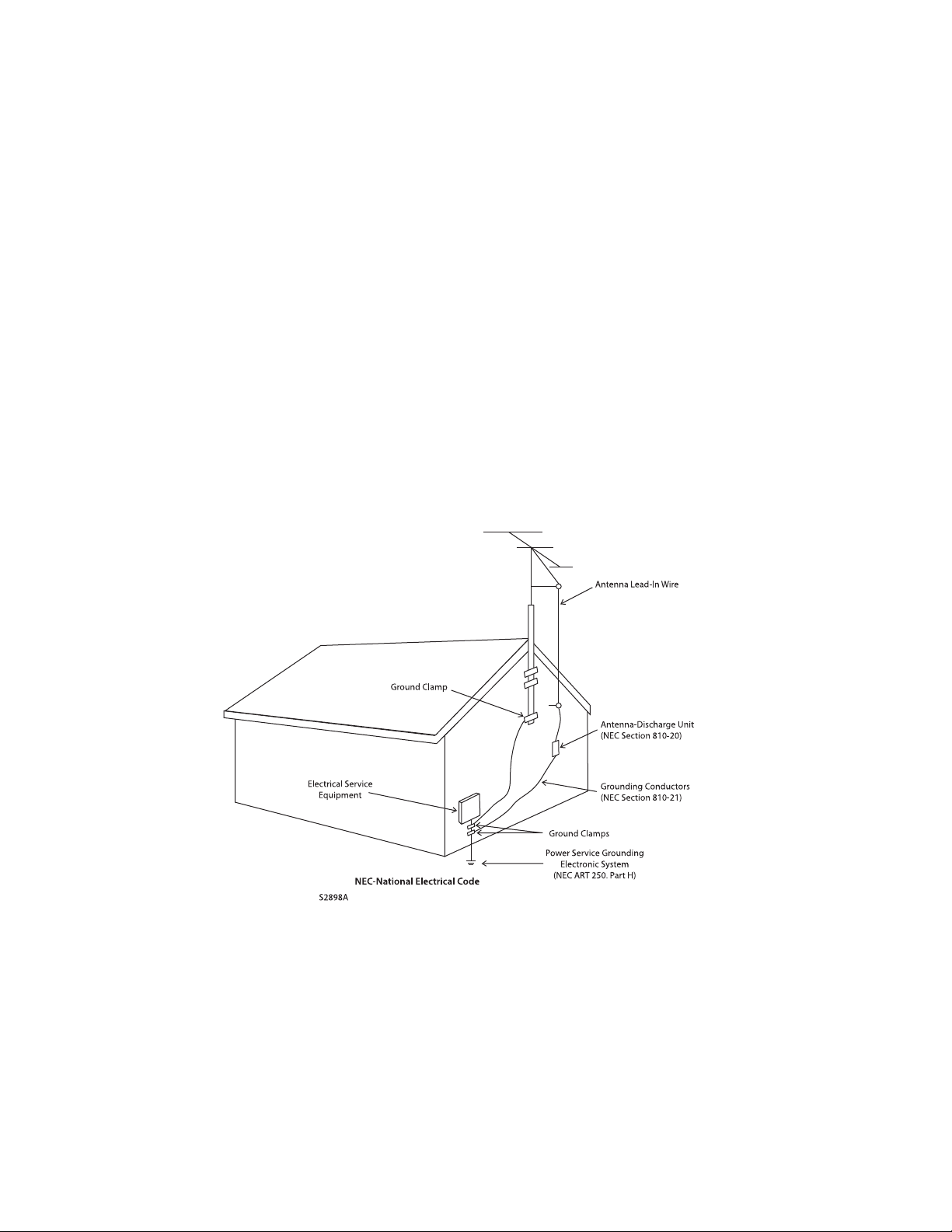
12. Outdoor Antenna Grounding – If an outside antenna or cable system is connected to the product, be sure the antenna
or cable system is grounded so as to provide some protection against voltage surges and built-up static charges. Article
810 of the National Electrical Code, ANSI/NFPA 70, provides information with regard to the proper grounding of the mast
and supporting structure, grounding of the lead-in wire to an antenna-discharge unit, size of grounding conductors,
location of antenna-discharge unit, connection to grounding electrodes, and requirements for the grounding electrode.
13. Lightning – For added protection for this product during a lightning storm, or when it is left unattended and unused for
long periods of time, unplug it from the wall outlet and disconnect the antenna or cable systems. This will prevent
damage to the product due to lightning and power-line surges.
14. Power Lines – An outside antenna system should not be located in the vicinity of overhead power lines or other electric
light or power circuits, or where it can fall into such power lines or circuits. When installing an outside antenna system,
extreme care should be taken to keep from touching such power lines or circuits as contact with them might be fatal.
15. Overloading – Do not overload wall outlets, extension cords, or integral convenience receptacles as this can result in
a risk of fire or electric shock.

Anthem, AnthemLogic, ARC, Sonic Frontiers, and Paradigm are trademarks or registered trademarks of Paradigm Electronics Inc.
Copyright Paradigm Electronics Inc. All rights reserved. The information contained herein may not be reproduced
in whole or in part without our express written permission. We reserve the right to change specifications and/or features
without notice as design improvements are incorporated.
Manufactured under license from Dolby Laboratories. Dolby, Pro Logic, and
the double-D symbol are trademarks of Dolby Laboratories.
Manufactured under license under U.S. Patent #’s: 5,451,942; 5,956,674; 5,974,380; 5,978,762; 6,226,616; 6,487,535; 7,212,872;
7,333,929; 7,392,195; 7,272,567 & other U.S. and worldwide patents issued & pending. DTS is a registered trademark and the DTS
logos, Symbol, DTS-HD and DTS-HD Master Audio are trademarks of DTS, Inc. © 1996-2008 DTS, Inc. All Rights Reserved.
Manufactured under license from THX Ltd. U.S. patent numbers 5,043,970; 5,189,703; and/or 5,222,059. European patent number
0323830. Other U.S. and foreign patents pending. Ultra2 and THX are trademarks or registered trademarks of THX Ltd. Lucasfilm is
a trademark of Lucasfilm Ltd. Surround EX is a trademark of Dolby Laboratories. Used under authorization.
This product incorporates copyright protection technology that is protected by U.S. patents and other intellectual property rights.
Use of this copyright protection technology must be authorized by Macrovision, and is intended for home and other limited
viewing uses only unless otherwise authorized by Macrovision. Reverse engineering or disassembly is prohibited.
HDMI, the HDMI logo and High-Definition Multimedia Interface are trademarks or registered trademarks of HDMI Licensing LLC.
VXP, Visual Excellence Processing and the VXP logo are trademarks or registered trademarks of Sigma Designs, Inc.
All other trademarks are the property of their respective owners.
RECYCLING AND REUSE GUIDELINES (Europe)
In accordance with the European Union WEEE (Waste Electrical and Electronic Equipment) directive effective
August 13, 2005, we would like to notify you that this product may contain regulated materials which, upon disposal,
require special reuse and recycling processing. For this reason Paradigm Electronics Inc. (the manufacturer of
Paradigm speakers and Anthem electronic products) has arranged with its distributors in European Union member
nations to collect and recycle this product at no cost to you. To find your local distributor please contact the dealer
from whom you purchased this product or go to our website at www.paradigm.com.
Please note that only the product falls under the WEEE directive. When disposing of packaging and other shipping
material we encourage you to recycle through the normal channels.
16. Object and Liquid Entry – Never push objects of any kind through openings as they may touch dangerous voltage points
or short-out parts that could result in a fire or electric shock. Do not expose this product to dripping or splashing and
ensure that no objects filled with liquids, such as vases, are placed on the product.
17. Servicing – Do not attempt to service this product yourself, as opening or removing covers may expose you to
dangerous voltage or other hazards. Refer all servicing to qualified service personnel.
18. Damage Requiring Service – Unplug this product from the wall outlet and refer servicing to qualified personnel under
the following conditions:
• When power-supply cord or plug is damaged.
• If liquid has been spilled, or objects have fallen into the product.
• If the product has been exposed to rain or water.
• If the product does not operate normally by following the operating instructions. Adjust only those controls that are
covered by the operating instructions as an improper adjustment of other controls may result in damage and will require
extensive work by a qualified technician to restore the product to its normal operation.
• If the product has been dropped or damaged in any way.
• If the product exhibits a distinct change in performance – this indicates a need for service.
19. Replacement Parts – When replacement parts are required, be sure the technician has used replacement parts
specified by the manufacturer or have the same characteristics as the original part. Unauthorized substitutions may
result in fire, electric shock, or other hazards.
20. Safety Check – Upon completion of any service or repairs to this product, ask the service technician to perform safety
checks to determine that the product is in proper operating condition.
21. Heat – The product should be situated away from heat sources such as radiators, heat registers, stoves, or other
products (including amplifiers) that produce heat.

SECTION PAGE
1. INTRODUCTION
1.1 Before Making Connections. . . . . . . . . . . . . . . . . . . . . . . . . . . . . . . . . . . . . . . . . . . . . . . . . . . . . . . . . . . . . 1
1.2 In-Use Notices . . . . . . . . . . . . . . . . . . . . . . . . . . . . . . . . . . . . . . . . . . . . . . . . . . . . . . . . . . . . . . . . . . . . . . . . 1
1.3 Front Panel . . . . . . . . . . . . . . . . . . . . . . . . . . . . . . . . . . . . . . . . . . . . . . . . . . . . . . . . . . . . . . . . . . . . . . . . . . . . 2
1.4 Front Panel Display . . . . . . . . . . . . . . . . . . . . . . . . . . . . . . . . . . . . . . . . . . . . . . . . . . . . . . . . . . . . . . . . . . . . . 3
1.5 Rear Panel . . . . . . . . . . . . . . . . . . . . . . . . . . . . . . . . . . . . . . . . . . . . . . . . . . . . . . . . . . . . . . . . . . . . . . . . . . . . 4
1.6 Remote Control . . . . . . . . . . . . . . . . . . . . . . . . . . . . . . . . . . . . . . . . . . . . . . . . . . . . . . . . . . . . . . . . . . . . . . . . 5
1.7 Speaker Placement . . . . . . . . . . . . . . . . . . . . . . . . . . . . . . . . . . . . . . . . . . . . . . . . . . . . . . . . . . . . . . . . . . . . . 6
1.8 Interconnects . . . . . . . . . . . . . . . . . . . . . . . . . . . . . . . . . . . . . . . . . . . . . . . . . . . . . . . . . . . . . . . . . . . . . . . . . 7
2. CONNECTIONS
2.1 Video . . . . . . . . . . . . . . . . . . . . . . . . . . . . . . . . . . . . . . . . . . . . . . . . . . . . . . . . . . . . . . . . . . . . . . . . . . . . . . . . . 8
2.2 Audio . . . . . . . . . . . . . . . . . . . . . . . . . . . . . . . . . . . . . . . . . . . . . . . . . . . . . . . . . . . . . . . . . . . . . . . . . . . . . . . . . 9
2.3 FM•AM Antennas . . . . . . . . . . . . . . . . . . . . . . . . . . . . . . . . . . . . . . . . . . . . . . . . . . . . . . . . . . . . . . . . . . . . . 11
2.4 12 Volt Triggers . . . . . . . . . . . . . . . . . . . . . . . . . . . . . . . . . . . . . . . . . . . . . . . . . . . . . . . . . . . . . . . . . . . . . . . 11
2.5 Powered IR (Infra Red) Receivers . . . . . . . . . . . . . . . . . . . . . . . . . . . . . . . . . . . . . . . . . . . . . . . . . . . . . . . 11
2.6 IR (Infra Red) Emitters . . . . . . . . . . . . . . . . . . . . . . . . . . . . . . . . . . . . . . . . . . . . . . . . . . . . . . . . . . . . . . . . . . 11
2.7 Power. . . . . . . . . . . . . . . . . . . . . . . . . . . . . . . . . . . . . . . . . . . . . . . . . . . . . . . . . . . . . . . . . . . . . . . . . . . . . . . . 11
3. SETUP
Entering / Navigating / Exiting the Setup Menu . . . . . . . . . . . . . . . . . . . . . . . . . . . . . . . . . . . . . . . . . . . . . . . 15
3.1 Video Output . . . . . . . . . . . . . . . . . . . . . . . . . . . . . . . . . . . . . . . . . . . . . . . . . . . . . . . . . . . . . . . . . . . . . . . . . 16
3.2 Set Time and Timers. . . . . . . . . . . . . . . . . . . . . . . . . . . . . . . . . . . . . . . . . . . . . . . . . . . . . . . . . . . . . . . . . . . 21
3.3 Speaker Configuration. . . . . . . . . . . . . . . . . . . . . . . . . . . . . . . . . . . . . . . . . . . . . . . . . . . . . . . . . . . . . . . . . 24
3.4 Listener Position . . . . . . . . . . . . . . . . . . . . . . . . . . . . . . . . . . . . . . . . . . . . . . . . . . . . . . . . . . . . . . . . . . . . . . 29
3.5 Level Calibration . . . . . . . . . . . . . . . . . . . . . . . . . . . . . . . . . . . . . . . . . . . . . . . . . . . . . . . . . . . . . . . . . . . . . 30
3.6 Source Setup . . . . . . . . . . . . . . . . . . . . . . . . . . . . . . . . . . . . . . . . . . . . . . . . . . . . . . . . . . . . . . . . . . . . . . . . . 32
3.7 Mode Presets. . . . . . . . . . . . . . . . . . . . . . . . . . . . . . . . . . . . . . . . . . . . . . . . . . . . . . . . . . . . . . . . . . . . . . . . . 36
3.8 Analog Input Levels. . . . . . . . . . . . . . . . . . . . . . . . . . . . . . . . . . . . . . . . . . . . . . . . . . . . . . . . . . . . . . . . . . . . 37
3.9 ADC and Audio Output . . . . . . . . . . . . . . . . . . . . . . . . . . . . . . . . . . . . . . . . . . . . . . . . . . . . . . . . . . . . . . . . 38
3.10 Volumes and Path Names . . . . . . . . . . . . . . . . . . . . . . . . . . . . . . . . . . . . . . . . . . . . . . . . . . . . . . . . . . . . . . 39
3.11 Triggers, IR, and RS-232 . . . . . . . . . . . . . . . . . . . . . . . . . . . . . . . . . . . . . . . . . . . . . . . . . . . . . . . . . . . . . . . 40
3.12 Displays and Timeout. . . . . . . . . . . . . . . . . . . . . . . . . . . . . . . . . . . . . . . . . . . . . . . . . . . . . . . . . . . . . . . . . . 42
3.13 Save and Load Settings . . . . . . . . . . . . . . . . . . . . . . . . . . . . . . . . . . . . . . . . . . . . . . . . . . . . . . . . . . . . . . . . 44
3.14 Lockout and Passwords . . . . . . . . . . . . . . . . . . . . . . . . . . . . . . . . . . . . . . . . . . . . . . . . . . . . . . . . . . . . . . . 45
3.15 ARC-1 Anthem Room Correction . . . . . . . . . . . . . . . . . . . . . . . . . . . . . . . . . . . . . . . . . . . . . . . . . . . . . . . . 46
TABLE of CONTENTS

4. OPERATION
4.1 Power On and Off . . . . . . . . . . . . . . . . . . . . . . . . . . . . . . . . . . . . . . . . . . . . . . . . . . . . . . . . . . . . . . . . . . . . . 50
4.2 Path Selection . . . . . . . . . . . . . . . . . . . . . . . . . . . . . . . . . . . . . . . . . . . . . . . . . . . . . . . . . . . . . . . . . . . . . . . . 50
4.3 Manually Copying the Main Path to Zone2/3 and Record . . . . . . . . . . . . . . . . . . . . . . . . . . . . . . . . . . . 51
4.4 Source Selection . . . . . . . . . . . . . . . . . . . . . . . . . . . . . . . . . . . . . . . . . . . . . . . . . . . . . . . . . . . . . . . . . . . . . 51
4.4.1 FM• AM Tuner 52
4.4.2 Simulcast 52
4.5 Volume Control . . . . . . . . . . . . . . . . . . . . . . . . . . . . . . . . . . . . . . . . . . . . . . . . . . . . . . . . . . . . . . . . . . . . . . . 53
4.6 Level Trim . . . . . . . . . . . . . . . . . . . . . . . . . . . . . . . . . . . . . . . . . . . . . . . . . . . . . . . . . . . . . . . . . . . . . . . . . . . 53
4.7 Bass, Treble, and Balance . . . . . . . . . . . . . . . . . . . . . . . . . . . . . . . . . . . . . . . . . . . . . . . . . . . . . . . . . . . . . 54
4.8 Surround Modes . . . . . . . . . . . . . . . . . . . . . . . . . . . . . . . . . . . . . . . . . . . . . . . . . . . . . . . . . . . . . . . . . . . . . . 54
4.8.1 AnthemLogic 55
4.8.2 Dolby Digital 2.0 55
4.8.3 Surround Modes for 2.0-Channel Sources 56
4.8.4 Dolby Digital 57
4.8.5 DTS 57
4.8.6 THX 58
4.8.7 Mode and THX options for 2.0-channel sources 60
4.8.8 Mode and THX options for 5.1-channel Dolby sources and 6-Ch S/E 61
4.8.9 Mode and THX options for 5.1-channel DTS sources 62
4.8.10 Dynamics 63
4.9 Lip-Sync Delay . . . . . . . . . . . . . . . . . . . . . . . . . . . . . . . . . . . . . . . . . . . . . . . . . . . . . . . . . . . . . . . . . . . . . . . . 63
4.10 Display Brightness . . . . . . . . . . . . . . . . . . . . . . . . . . . . . . . . . . . . . . . . . . . . . . . . . . . . . . . . . . . . . . . . . . . 63
4.11 Video Source Adjustment . . . . . . . . . . . . . . . . . . . . . . . . . . . . . . . . . . . . . . . . . . . . . . . . . . . . . . . . . . . . . . 64
Picture 65
Crop Input 67
Scale Output 68
Aspect Ratio Control Examples 69
Output 71
Test Patterns 72
Info Panel 73
Shortcuts and emergency exits 73
4.12 Sleep Timer . . . . . . . . . . . . . . . . . . . . . . . . . . . . . . . . . . . . . . . . . . . . . . . . . . . . . . . . . . . . . . . . . . . . . . . . . . . 74
4.13 Enable and Disable Timers. . . . . . . . . . . . . . . . . . . . . . . . . . . . . . . . . . . . . . . . . . . . . . . . . . . . . . . . . . . . . 74
4.14 Status Display. . . . . . . . . . . . . . . . . . . . . . . . . . . . . . . . . . . . . . . . . . . . . . . . . . . . . . . . . . . . . . . . . . . . . . . . . 74
5. REMOTE CONTROL CUSTOMIZATION
5.1 Codes for Other Brands . . . . . . . . . . . . . . . . . . . . . . . . . . . . . . . . . . . . . . . . . . . . . . . . . . . . . . . . . . . . . . . . 75
5.2 Learning Commands. . . . . . . . . . . . . . . . . . . . . . . . . . . . . . . . . . . . . . . . . . . . . . . . . . . . . . . . . . . . . . . . . . . 75
5.3 Copying Commands . . . . . . . . . . . . . . . . . . . . . . . . . . . . . . . . . . . . . . . . . . . . . . . . . . . . . . . . . . . . . . . . . . . . 76
5.4 Volume Lock . . . . . . . . . . . . . . . . . . . . . . . . . . . . . . . . . . . . . . . . . . . . . . . . . . . . . . . . . . . . . . . . . . . . . . . . . 76
5.5 Programming Macros . . . . . . . . . . . . . . . . . . . . . . . . . . . . . . . . . . . . . . . . . . . . . . . . . . . . . . . . . . . . . . . . . . 77
5.6 Resetting the Remote Control . . . . . . . . . . . . . . . . . . . . . . . . . . . . . . . . . . . . . . . . . . . . . . . . . . . . . . . . . . 77

6. SOFTWARE UPDATING
6.1 Software Version Identification . . . . . . . . . . . . . . . . . . . . . . . . . . . . . . . . . . . . . . . . . . . . . . . . . . . . . . . . 78
6.2 Software Updating Via Your Dealer . . . . . . . . . . . . . . . . . . . . . . . . . . . . . . . . . . . . . . . . . . . . . . . . . . . . . . 78
6.3 Software Updating Via Your Computer and the Internet . . . . . . . . . . . . . . . . . . . . . . . . . . . . . . . . . . . . 78
Appendix A – IR Macros for Surround Modes and FM•AM Banks 80
Appendix B – Preset Memory Codes 81
Specifications 88
Warranty 91
Big Pictures of Front and Rear Panels Inside Back Cover


1
1. INTRODUCTION
Thank you for purchasing the Anthem AVM 50v processor.
The AVM 50v is a cutting-edge home theater audio processor with HDMI switching and video upconversion,
multizone capabilities, and FM/AM tuner, along with state of the art video processing which includes
deinterlacing, scaling, aspect ratio control, and picture adjustment. Anthem products are engineered to
recreate the passion of live performance and thrill of the best movie theaters by using the highest level of
circuit design, proprietary software, superior build quality, innovative features, and intuitive ergonomics with
tremendous flexibility.
1.1 BEFORE MAKING CONNECTIONS
Check that you have received everything listed below and report discrepancies to your dealer as soon as
possible. In case they are needed one day, keep the packing materials and the invoice that you received from
your authorized Anthem dealer at time of purchase – without it, service will not be provided under warranty.
Packing List:
• AVM 50v • FM antenna • IR terminal block (on rear panel)
• Remote control • FM antenna adapter • Power cord (North America only)
• 2 AA batteries • AM loop antenna • Keyspan USB-serial adapter
Additional items with ARC-1 Anthem Room Correction:
• Software installation CD • Microphone and clip • Telescopic stand
• Serial extension cable • USB microphone cable • Base
Safety Instructions:
• Read all precautions and instructions at the beginning of this manual.
• Do not connect power if there are signs of damage to any part of the exterior.
• The front panel power buttons and the rear panel AC switch do not disconnect the product from the
AC line. Ensure that the power cord remains readily accessible at all times.
• To connect power, only use the supplied double-insulated power cord.
• Allow adequate ventilation to ensure reliable operation and to prevent overheating. The amount of
space required above the unit for radiation depends on ambient air temperature and circulation.
Installation inside an unventilated space such as a cabinet with a front that can be closed or a
closet is not recommended.
• Failing to comply with any safety instruction, precaution, or warning in this operating manual is in
violation of the intended use of the product.
• Anthem and any related party assume no liability for the user’s failure to comply with requirements.
1.2 IN-USE NOTICES
• Disconnect the power cord before connecting or disconnecting any components.
• If the processor was transported or stored in the cold, let it warm to room temperature before use.
• Do not remove the top cover.
• Do not modify the product.
• Due to continuing advances operational characteristics may change. If this manual contains
discrepancies please check www.anthemAV.com for the latest manual or software.
2
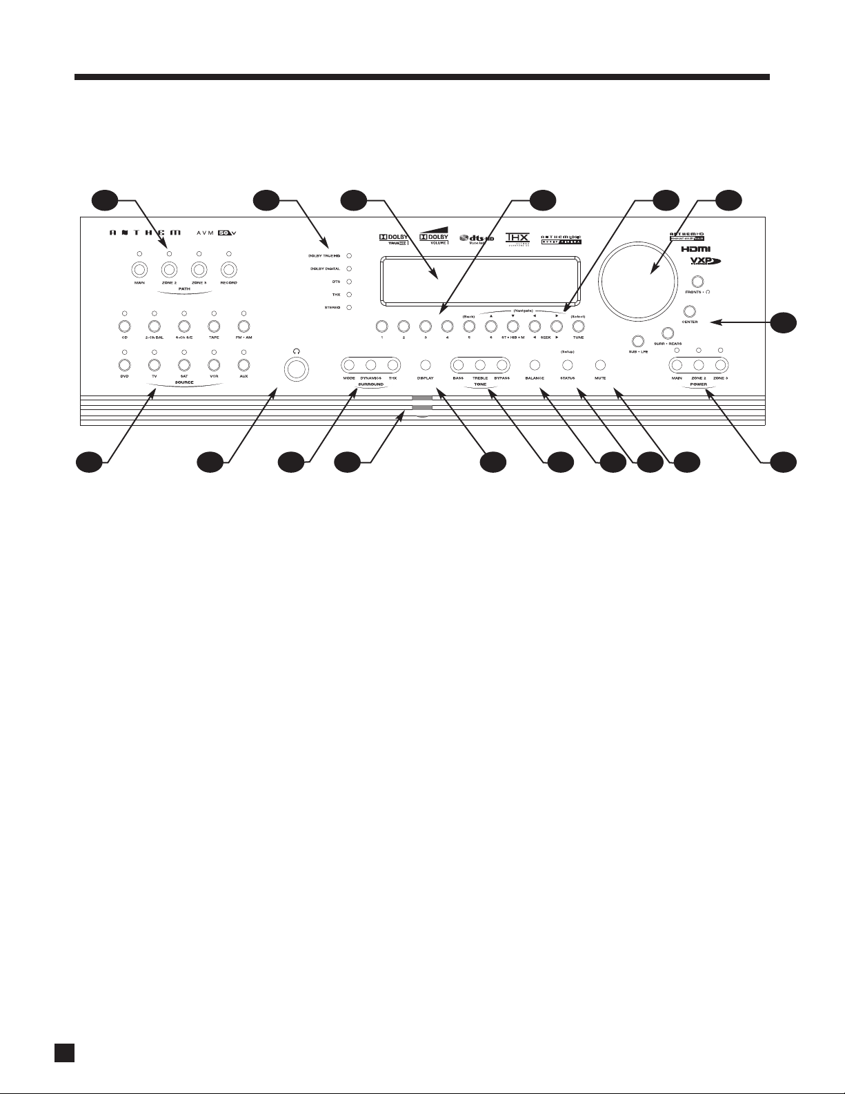
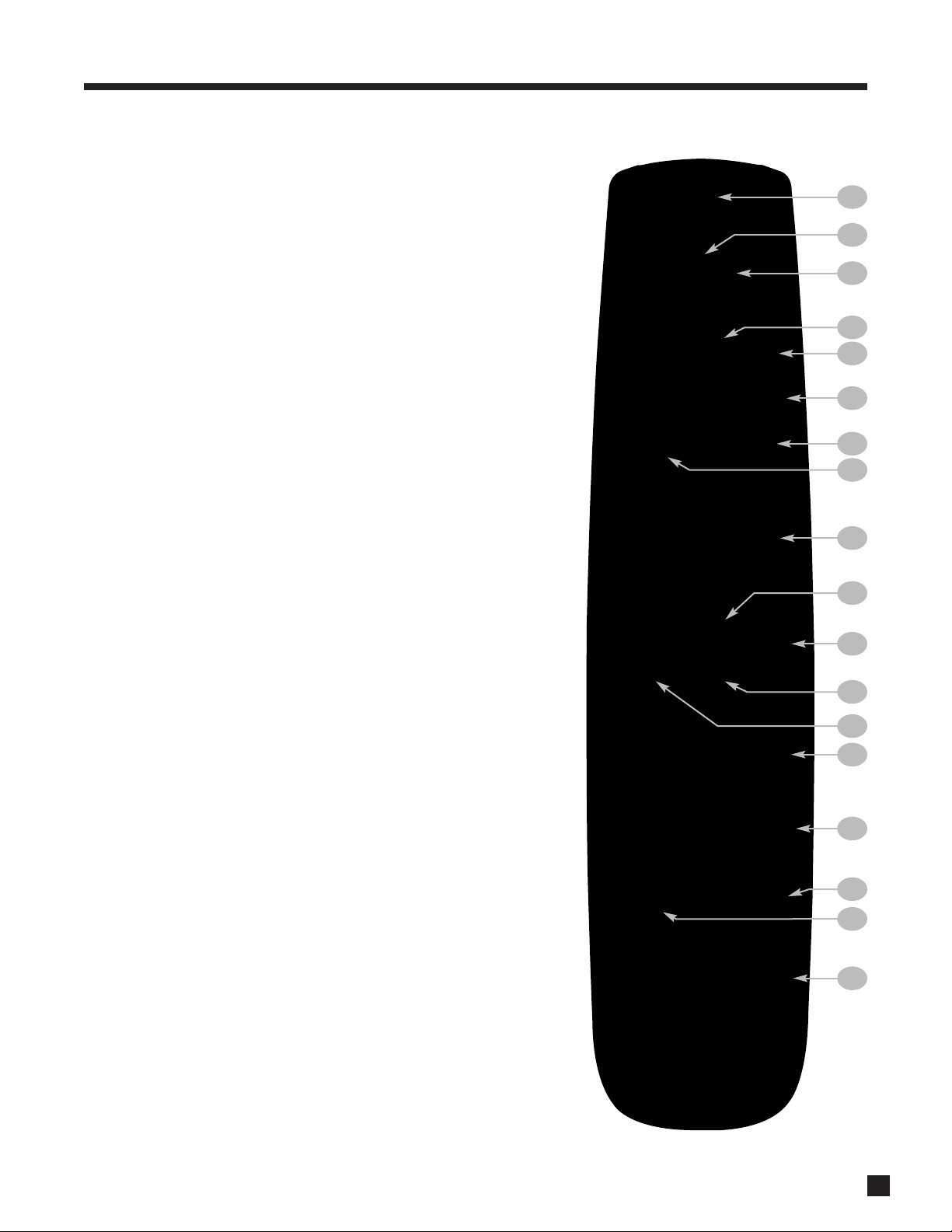
1.3 FRONT PANEL
1 – Path selection
2 – Mode and decoder indicators
3 – Display
4 –FM • AM preset selection
5 –FM • AM tuning / setup menu navigation
6 – Master Control Knob:
• Volume
• Tune for FM • AM
• Settings adjustment
• Setup for time and source naming
7 – Speaker group and headphone access
8 – Power on / standby
9 – Mute
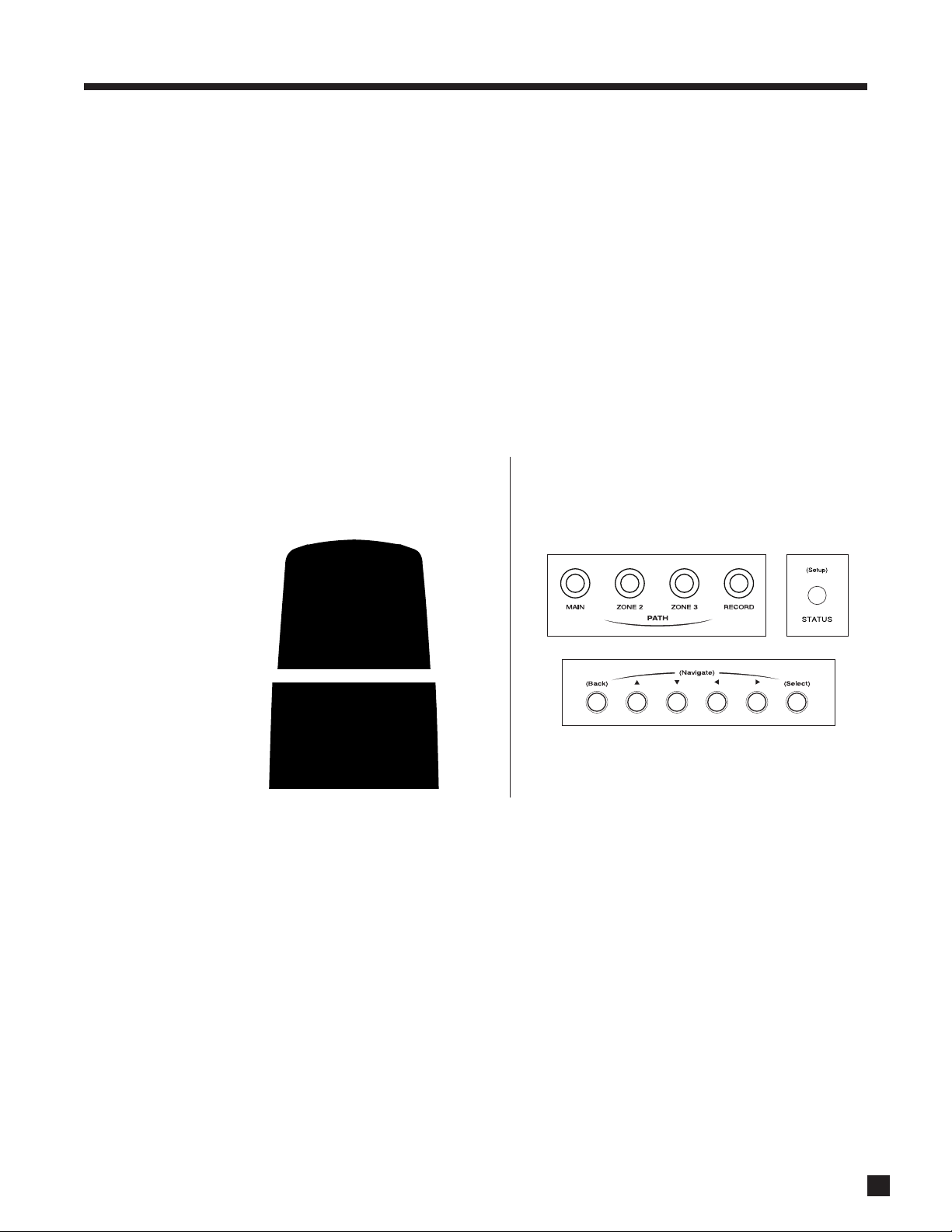
10 – Status review / setup menu access
11 – Balance setting
12 – Bass / treble settings
13 – LED and display brightness setting / video adjustment
menu access
14 – Front panel IR sensor
15 – Surround mode / Dynamics / THX options / shortcuts
to most common video adjustments
16 – Headphone jack
17 – Source selection
1. INTRODUCTION continued …
For a larger diagram see inside back cover.
1617 15 14 13 12 11 10 9 8
7
5 64321

3
1.4 FRONT PANEL DISPLAY
MAIN Display Example:
1 – Source selection.
2 – Audio input format or sleep timer if engaged.
3 – Video input
resolution.
4 – Volume.
5 – Number of input channels + surround mode.
FM • AM Display Example:
1 – Band+bank+preset. The tuner has three FM banks (FM1, FM2, and FM3) and one AM bank.
2 – FM mode. Displays “St” when in stereo, “HB” when in Hi-Blend, or “Mn” when in mono.
3 – Seek and scan indications.
4 – Frequency. FM is tuned to the nearest 0.1 MHz. AM is tuned to nearest 10 kHz (120V model) or
9 kHz (230V model).
The above information is also shown on-screen. For the video outputs that produce it, see section 3.
1. INTRODUCTION continued …
5
4
32
1
4
1
32
DVD1 DolbyHD 1080p
5. 1+PLIIx Movie -7. 5
FM2-5 St Sk > 480i
101. 3 MHz -18. 5 dB
23
24
25
22
20
19
21
141516 1317
18
8 95 6
7
10
11
2
3
1
4
12
4
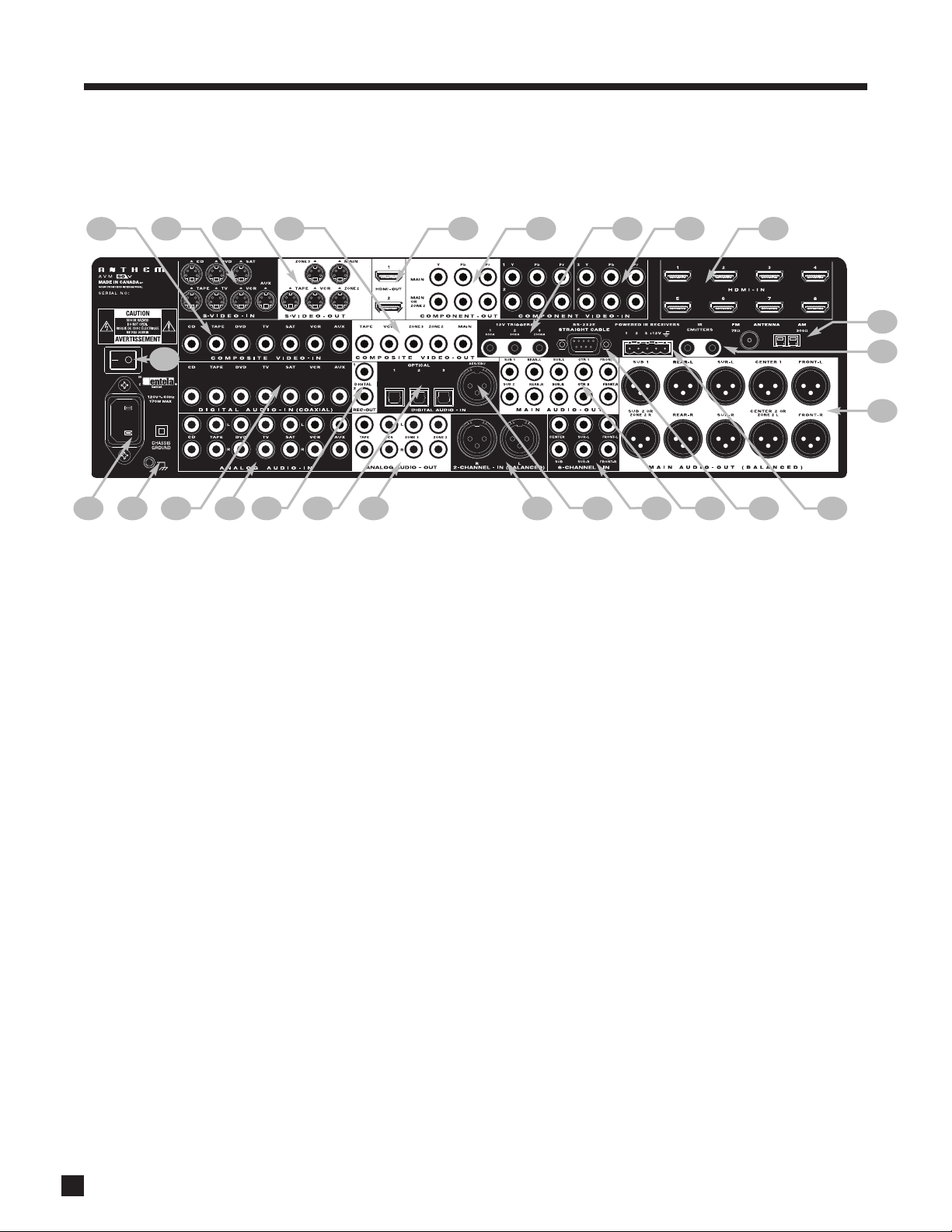
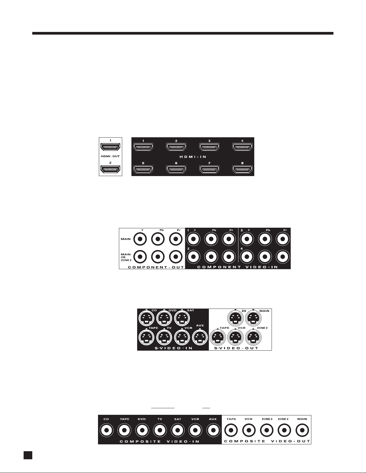
1 – 7 composite video inputs
2 – 7 S-Video inputs
3 – 5 S-Video outputs
4 – 5 composite video outputs
5 – 2 HDMI outputs (parallel)
6 – 2 component video outputs (3 jacks/ea)
7 – 3 12V trigger outputs
8 – 4 component video inputs (3 jacks/ea)
9 – 8 HDMI inputs
10 – FM and AM antenna connections
11 – 2 IR emitters
12 – Main audio output (10 balanced jacks)
13 – 3 IR extension inputs with 12V supply
14 – RS-232 interface (bidirectional)
15 – Main audio output (10 jacks)
16 – 6-channel analog audio input
17 – AES/EBU digital audio input
18 – Analog audio balanced L/R input
19 – ZONE2, ZONE3, and REC analog audio outputs
20 – 3 optical digital audio inputs
21 – 2 digital audio REC outputs
22 – 7 analog audio L/R inputs
23 – 7 digital audio coaxial inputs
24 – Ground terminal
25 – Power cord connection
26 – AC switch
1.5 REAR PANEL
For a larger diagram see inside back cover.
1. INTRODUCTION continued …
26
5
1.6 REMOTE CONTROL
1 – Learn – for customization of remote
2 – Power On and Power Off
3 – Control mode. These are not source selection keys (see #17).
4 – • Copy MAIN when ZONE2, ZONE3, or RECORD is selected.
• LIST for PVRs.
5 – Previous / next source seek
6 – Bass / treble selection for adjustment
7 – RECORD path selection (must be in MAIN control mode)
8 – Balance
9 – Navigation:
• Setup menu (press and hold Menu for 3 seconds)
• Back (for setup)
• Status (press Select)
• FM • AM direct entry (press and hold Select for 3 seconds)
• FM • AM tuning
• Adjustment for surround mode, dynamics, THX,
levels, bass, treble, timers, brightness, and lip-sync
• FM • AM seek
• Adjustment for balance and lip-sync
10 – THX selection
11 –FM • AM preset up/down
12 – Sleep timer selection / timers setting
13 – Volume up/down and mute
14 – Channel selection for level, bass, treble, and balance
15 – Numeric pad and shortcuts:
• 1-6: FM • AM preset
• 7: Video processing menu (press and hold for 3 seconds)
• 8: Front panel brightness setting
• 8: Lip-sync selection (press and hold for 3 seconds)
• 9: Tone Bypass
• 0: Dynamics selection
• 0: Video input adjustments (press and hold for 3 seconds)
16 – • Surround mode selection
• Video selections (press and hold for 3 seconds)
17 – Next source
18 – Source selection
Front:
Infrared transmitter and receiver.
Bottom:
Battery cover. When battery voltage is low the control mode key will blink
5 times after a key is pressed.
1. INTRODUCTION continued …
34
34
4
2
8
10
12
16
17
13
9
5
6
7
1
3
11
18
15
14
6
LAST
SLEEP
INPUT
FRT
CTR
T
H
X
T
I
M
E
R
S
S
T
A
T
U
S
PIPSWAP
MOVE
AVM SOURCE
COPY
AUX
TAPE
DVD
TV
SAT
VCR
CD
DVD
TV
SAT
VCR
B
A
S
S
T
R
E
B
L
E
B
A
L
A
N
C
E
2-Ch
CD
REC
MAIN
Z2
Z3
AVM PATH
D
Y
N
A
M
I
C
S
VOLUME CH PRE-SET
FM/AM PRE-SETS
SEEK
TUNE
SOURCE SEEK
L
E
A
R
N
ENTER
MUTE
7
8
0
9
SELECT
SUB
LFE
FM
AM
SUR
RR
A
V
M
O
F
F
D
I
S
P
L
A
Y
T
O
N
E
B
Y
P
A
S
S
M
O
D
E
O
N
S
C
R
E
E
N
O
F
N
I
E
D
I
U
G
B
A
C
K
S
E
T
U
P
1
2
3
4
5
6
P
O
W
E
R
6-Ch
A
V
M
P
A
T
H
110˚ from center
LAST
SLEEP
INPUT
FRT
CTR
T
H
X
T
I
M
E
R
S
S
T
A
T
U
S
PIPSWAP
MOVE
AVM SOURCE
COPY
AUX
TAPE
DVD
TVSAT
VCR
CD
DVD
TV
SAT
VCR
B
A
S
S
T
R
E
B
L
E
B
A
L
A
N
C
E
2-Ch
CD
REC
MAIN
Z2
Z3
AVM PATH
D
Y
N
A
M
I
C
S
VOLUME
CH PRE-SET
FM/AM PRE-SETS
SEEK
TUNE
SOURCE SEEK
L
E
A
R
N
ENTER
MUTE
SELECT
SUB
LFE
FM
AM
SUR
RR
A
V
M
O
F
F
D
I
S
P
L
A
Y
T
O
N
E
B
Y
P
A
S
S
M
O
D
E
O
N
S
C
R
E
E
N
O
F
N
I
E
D
I
U
G
B
A
C
K
S
E
T
U
P
P
O
W
E
R
6-Ch
A
V
M
P
A
T
H
LAST
SLEEP
INPUT
FRT
CTR
T
H
X
T
I
M
E
R
S
S
T
A
T
U
S
PIP
SWAP
MOVE
AVM SOURCE
COPY
AUX
TAPE
DVD
TV
SAT
VCR
CD
DVD
TV
SAT
VCR
B
A
S
S
T
R
E
B
L
E
B
A
L
A
N
C
E
2-Ch
CD
REC
MAIN
Z2
Z3
AVM PATH
D
Y
N
A
M
I
C
S
VOLUME CH PRE-SET
FM/AM PRE-SETS
SEEK
TUNE
SOURCE SEEK
L
E
A
R
N
ENTER
MUTE
7
8
0
9
SELECT
SUB
LFE
FM
AM
SUR
RR
A
V
M
O
F
F
D
I
S
P
L
A
Y
T
O
N
E
B
Y
P
A
S
S
M
O
D
E
O
N
S
C
R
E
E
N
O
F
N
I
E
D
I
U
G
B
A
C
K
S
E
T
U
P
1
2
3
4
5
6
P
O
W
E
R
6-Ch
A
V
M
P
A
T
H
1. INTRODUCTION continued …
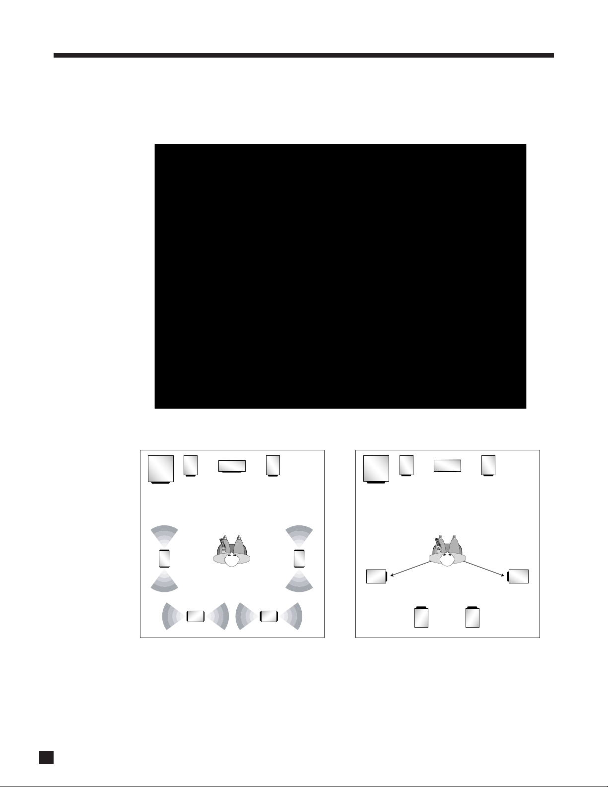
Dipole surrounds
Direct radiating surrounds
slightly behind listening position
1.7 SPEAKER PLACEMENT
The illustration below shows typical 7.1-channel speaker placement. The subwoofer can be placed in any
location where severe resonances are prevented – see section 3.3.
rear speakers are not
used in a 5.1 system

7
1.8 INTERCONNECTS
These illustrations show audio, video, IR, and trigger connectors used between source components, the
processor, displays, and power amplifiers. RCA coaxial cables with 75-ohm impedance are equally suitable
for analog video and digital audio.
Before calling for technical support due to bad, intermittent, or no picture via HDMI:
1080p uses twice the bandwidth that 720p and 1080i do – make sure that the cable is suitable for the
application otherwise the picture may contain pixel dropouts or not play at all.
Use HDMI Category 2 cables, also known as “v1.3 certified”. This is a requirement for all connecting devices
including extenders when connecting a display that supports Deep Color (10- or 12-bit). Connecting devices
that worked in an older setup may not work with Deep Color. If the source allows Deep Color to be turned
off, start troubleshooting by turning it off.
12-bit Deep Color that works at 1080p24 may not work at 1080p50 or 1080p60.
Be careful when connecting HDMI cables. The connector should easily slide in the jack – do not insert it on
an angle and do not force it. Each connector contains 19 delicate pins and damaged pins can damage jacks.
Such damaged jacks are not covered by warranty. If your HDMI cables have been connected enough times
that they are about to wear out, we recommend that you replace them.
If using DVI connection note that cables with DVI connection on one end and HDMI connection on the other
are more reliable than DVI-HDMI adapters. If you are having a connection problem and an adapter is in use,
start troubleshooting by eliminating the adapter.
Cable and satellite receivers: Some disable their component video output once HDMI is connected. To use
the cable/satellite box in a secondary zone that uses component video, connect the box to the processor via
component, not HDMI.
Older cable and satellite receivers: HDMI connection may be problematic especially when output resolution
changes between SD, 720p, and 1080i according to the channel. In such a case use component video
connection instead, with coaxial or optical connection for audio.
Analog Left
Channel
RCA Black or
White
RCA Red
RCA Yellow
Analog Right
Channel
Digital Audio or
Composite Video
RCA Green:
Component Y
RCA Blue:
Component Pb
RCA Red:
Component Pr
Mini DIN
HDMI
S-Video
Digital Video
and Audio
1. INTRODUCTION continued …
Optical
XLR Female
(connects to output)
XLR Male
(connects to input)
Digital Audio
Analog Balanced or AES/EBU
1/4” Stereo
Headphone
3.5mm
Mini (Mono)
12V Trigger
IR Emitter
8
2.1 VIDEO CONNECTIONS
To configure inputs see section 3.6 and to configure video outputs see section 3.1.
HDMI:
Video is sent with audio from source components to the processor. Maximum video resolution is 1080p60.
Connect MAIN HDMI output to a display with HDMI or DVI input – one with High-bandwidth Digital Content
Protection (HDCP) is required to display copy-protected material. DVD players usually enable HDCP even on
home movies. If the source is protected, only HDMI video output is active (see section 4.14).
3D sources must be connected to HDMI-IN 1-4 and the 3D display to HDMI-OUT 1. As well, the video output
must be set to Through – more info on this setting is in section 3.6.
Component Video:
Component video uses three coaxial cables and has a maximum resolution of 1080p when unprocessed or
480p when the source is copy-protected with Macrovision. Maximum input resolution is 1080i60 if the input
is processed or converted to HDMI. The second Component output can be used in MAIN, processed or
unprocessed, or in ZONE2.
S-Video:
Maximum resolution is 480i (NTSC) / 576i (PAL). This connection keeps brightness and color separate for a
better picture than Composite. S-Video input can be converted to Component and HDMI output (MAIN only).
Composite Video:
Maximum resolution is 480i (NTSC) / 576i (PAL). This traditional format combines the black/white and color
information for transmission on a single coaxial cable. To be displayed, the information has to be separated,
a process that degrades video quality. Composite inputs can not be converted or processed. If you use a
VCR, one with S-Video output is recommended. If a composite video source is black and white, it can be
plugged into a Component video’s Y input. If there is no choice but to convert a color source’s composite
output, a composite to S-Video converter
is needed (not an adapter turned backwards).
2. CONNECTIONS
HDMI switching requires
at least two seconds per
stage, i.e. at least four
seconds from source to
processor to display.
9
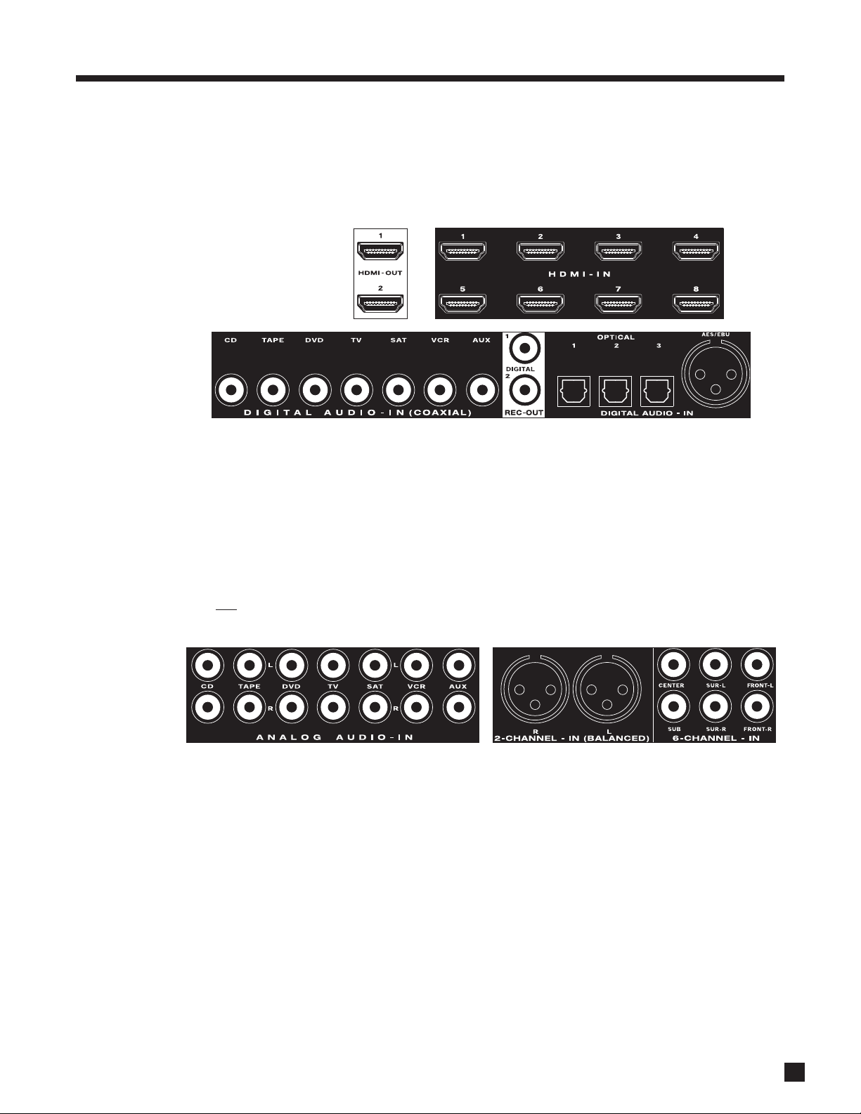
2.2 AUDIO CONNECTIONS
Digital Audio Inputs and Outputs:
Digital audio source components can be connected with a coaxial, optical, balanced, or HDMI cable. These
carry 2-channel PCM, Dolby Digital, and DTS. The HDMI inputs also accept up to eight channels of PCM.
Use the HDMI inputs if your display has HDCP-compliant HDMI or DVI input, otherwise use the coaxial or
optical inputs. The processor also provides one balanced AES/EBU connection, which is used on
professional equipment. Any digital input can be assigned to any number of sources that are set to digital.
To change digital audio connection from factory default, see section 3.6.
Digital Rec-Out can provide a signal to the digital audio input of a Mini Disc recorder, CD recorder etc. from
any source set to Digital (except HDMI) or Anlg-DSP – see sections 3.6 to 3.9.
Analog Audio Inputs:
Analog audio connections are made with RCA or XLR cables. To use ZONE2, ZONE3, or RECORD, connect
digital and
analog audio and video* from the source. ZONE2, ZONE3, and RECORD require analog connection
unless set to copy MAIN (explained in sections 3.6 and 4.3).
6-Ch Analog Input:
The 6-Ch input is for connecting DVD-Audio and multichannel SACD players that do not have HDMI output.
When 6-Ch is selected, the video signal from DVD input is routed to the video outputs by factory default – to
change this, see section 3.6.
2. CONNECTIONS continued …
Should you need
audio from the
HDMI output to
your display, it’s
2-channel PCM.
10
2. CONNECTIONS continued …
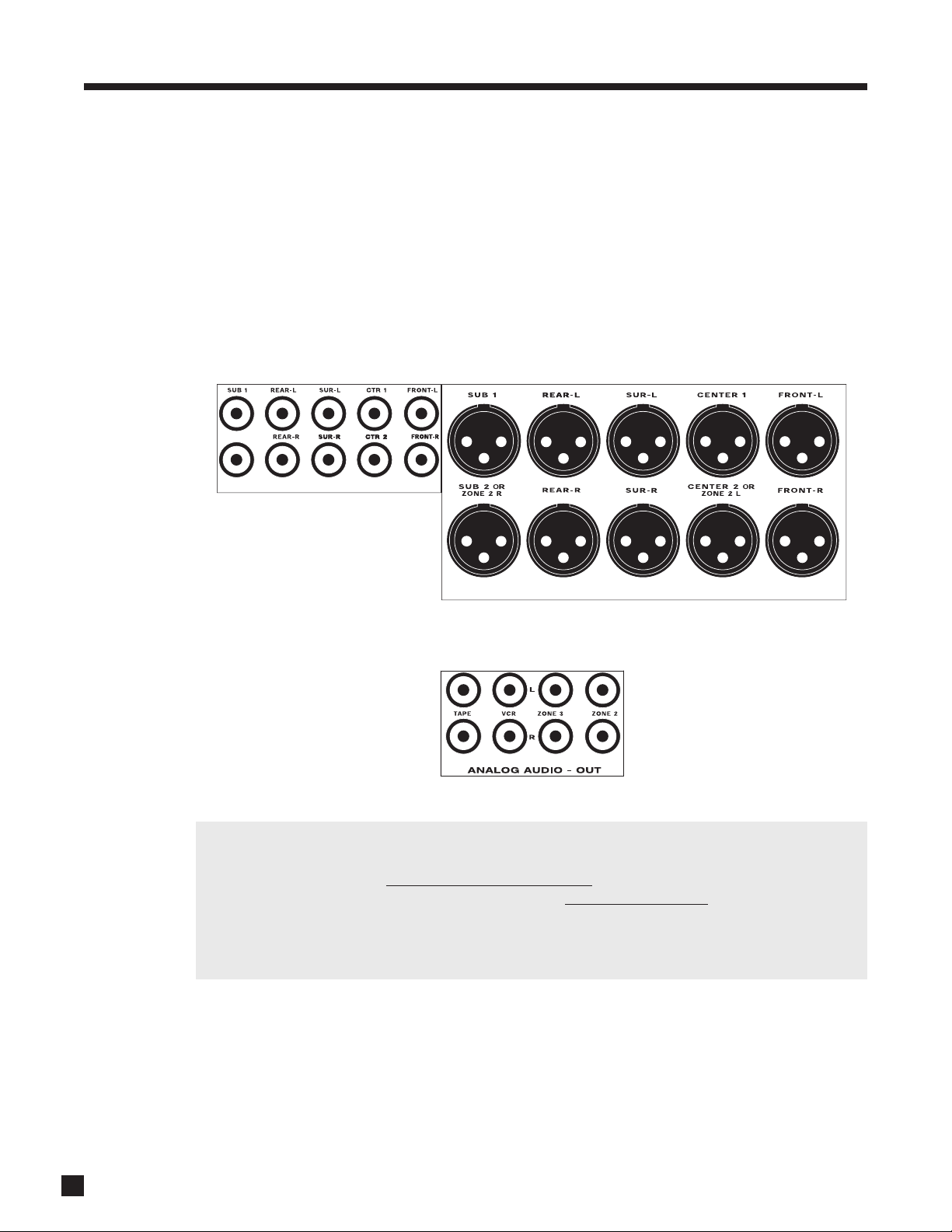
Analog Audio Outputs:
Balanced connection offers the highest transmission quality over long cable lengths, because it rejects
noise pickup. In the processor, XLR output voltage is twice that of RCA (6 dB higher). The RCA outputs and
the XLR outputs are always active – both can be used at the same time if the system requires it.
Parallel outputs are provided for a second center channel speaker and/or subwoofer. If your screen is large,
you might want to use one center channel speaker above it and another one below it. One way to tame room
resonances is by using multiple subwoofers playing the same signal from different locations in the room.
If you are not using the second set of balanced SUB2 and CENTER2 outputs, they can be reassigned as
ZONE2 L/R outputs to ensure noise rejection if the ZONE2 amplifier has balanced input and it’s at a distance
from the processor (see section 3.9).
If you’re using one rear channel, use the Rear-L output to connect it (see section 3.3).
Shown below are the analog audio RECORD outputs which connect to the audio inputs of recording devices,
together with the outputs that connect to amplifiers for ZONE2 and ZONE3:
Why am I not getting sound in ZONE2, ZONE3, or RECORD?
For ZONE2, ZONE3, and RECORD to have any output, the source components being used there must be
connected to the processor with the same type of connection
. For example, if a source is connected via
HDMI, there won’t be output in ZONE2 unless you make additional connections from the source to the
processor – analog L/R for audio, and Component, S-Video, or Composite video – whichever type the
display in ZONE2 uses.
The exception is when using Copy mode for audio – see section 4.3.
MAIN AUDIO-OUT (BALANCED)
SUB 2
MAIN AUDIO-OUT
11
2. CONNECTIONS continued …
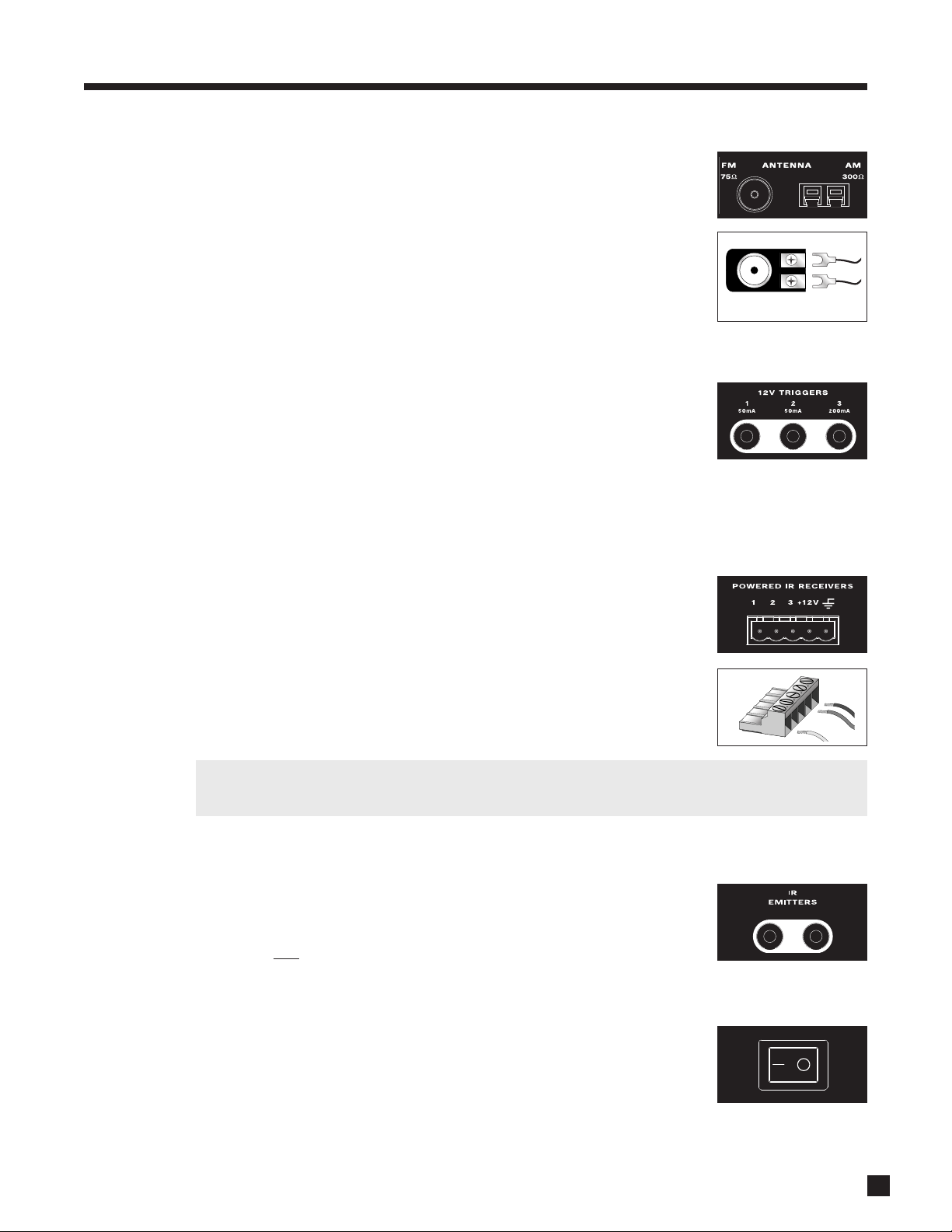
2.3 FM • AM ANTENNAS
To connect the AM loop antenna, press the spring-loaded tabs of the AM
ANTENNA connector and insert the bare ends of the two wires. Move the
antenna until best reception is found.
To connect the FM antenna, connect the two wires to the screw terminals of the
75-ohm to 300-ohm adapter, then connect the adapter to the FM ANTENNA
connector. Move the antenna until best reception is found – this is usually a “T”
formation. If your cable company provides FM service, you can connect the cable
to the processor.
2.4 12 VOLT TRIGGERS
If your other components have provisions for a trigger, you can have them turn on
and off together with the processor, or when a specified source is selected.
Connect a trigger output from the processor to the trigger input of your power
amplifier, display, etc., using a cable with 3.5mm mono mini plugs.
The processor provides flexible trigger options. From the factory, all the triggers are disabled. Through the
setup menu, you can specify the conditions for enabling triggers (see section 3.11).
2.5 POWERED IR (INFRA RED) RECEIVERS
External IR receivers allow the remote control to be used from other locations in
your home. Once an IR receiver is wired to another room, connect it to one of the
three IR RECEIVER inputs through the removable terminal block. To use the
terminal block, remove it from the processor, loosen the proper screw, insert the
wire in the slot, tighten the screw onto the wire, and insert the terminal block into
the processor. See section 3.11 for Setup information.
In addition, there is no need for an external 12V supply to power the receivers –
use the processor’s built-in supply instead for up to three IR receivers and
connect according to the IR receiver manufacturer’s instructions.
Custom Installers: The processor’s IR inputs sense modulated 38 kHz carrier, not demodulated data.
With some control systems, an emitter face-to-face with an IR receiver may be needed.
2.6 IR (INFRA RED) EMITTERS
IR emitters allow control of your source components from any location in your
home that has an IR receiver connected to the processor. After positioning the IR
emitter according to its instructions, connect it to IR EMITTER output. Commands
through the rear
IR RECEIVER are re-transmitted through the IR emitters.
2.7 POWER
Connect the power cord to the processor and the power source then turn on the
rear panel AC switch.
75-ohm to 300-ohm adapter
12
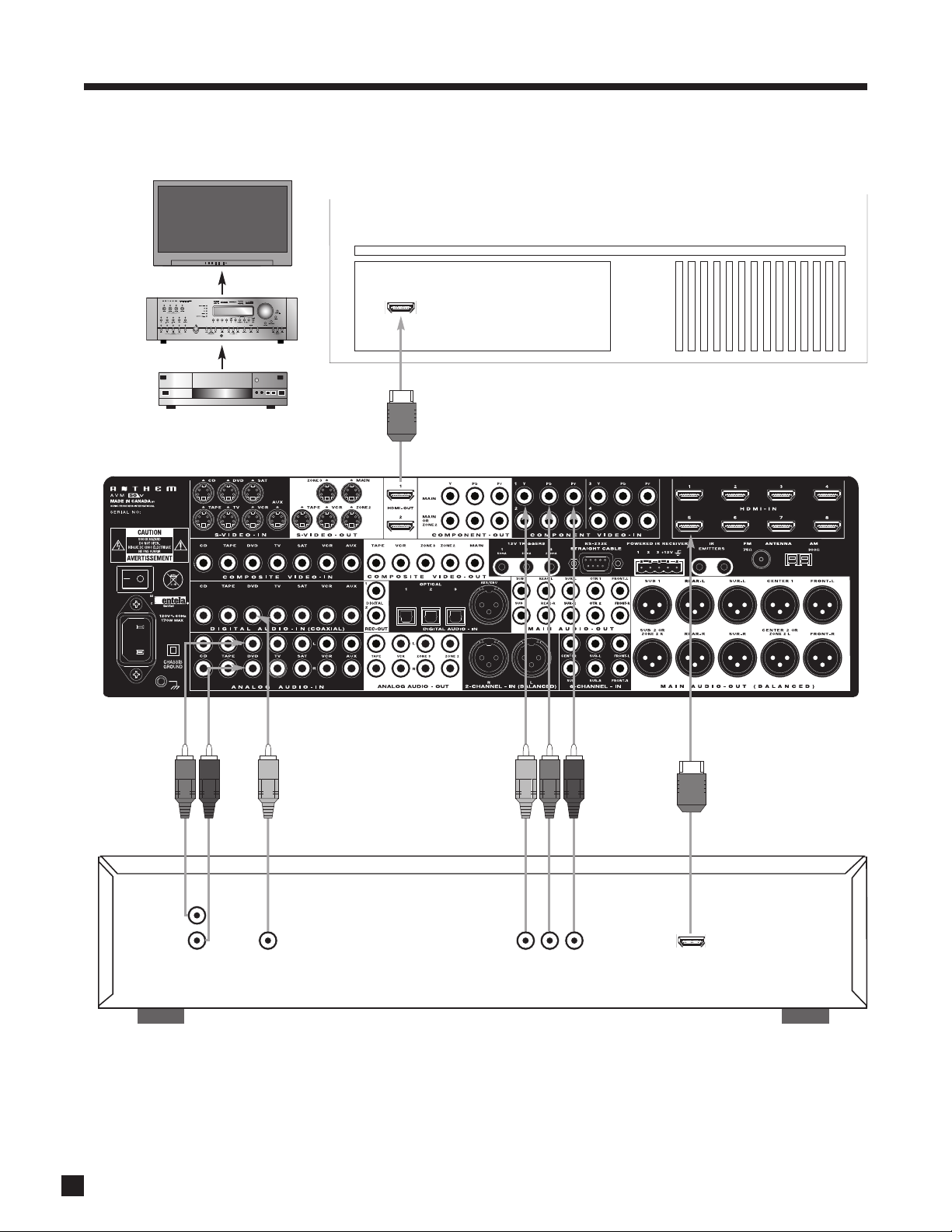
Example 1: Disc Player to processor to main display
2. CONNECTIONS continued …
DVD
Connect if using
digital REC-OUT or
if source’s video
output is DVI
HDMI IN
COAX
OUT
AUDIO
OUT
L
R
HDMI
OUT
YPbPr OUT
Connect for
MAIN
Connect if
using
ZONE2/3 or
REC
Connect if
using ZONE2
Cable and satellite receivers: HDTV receivers can be connected as above although if HDMI is problematic use component
video connection instead, with coaxial or optical connection for audio.

13
2. CONNECTIONS continued …
Example 2: A/V Recorder to processor
VCR
EJECT
AUDIO
OUT
L
R
AUDIO
IN
For ZONE2, ZONE3, and
REC, in most cases you
must use the same input
type as the output type.
If MAIN uses a different
input connection, all you
need to do is add these
connections for ZONE2,
ZONE3, and REC.
VIDEO
OUT
VIDEO
IN
L
R
14
2. CONNECTIONS continued …
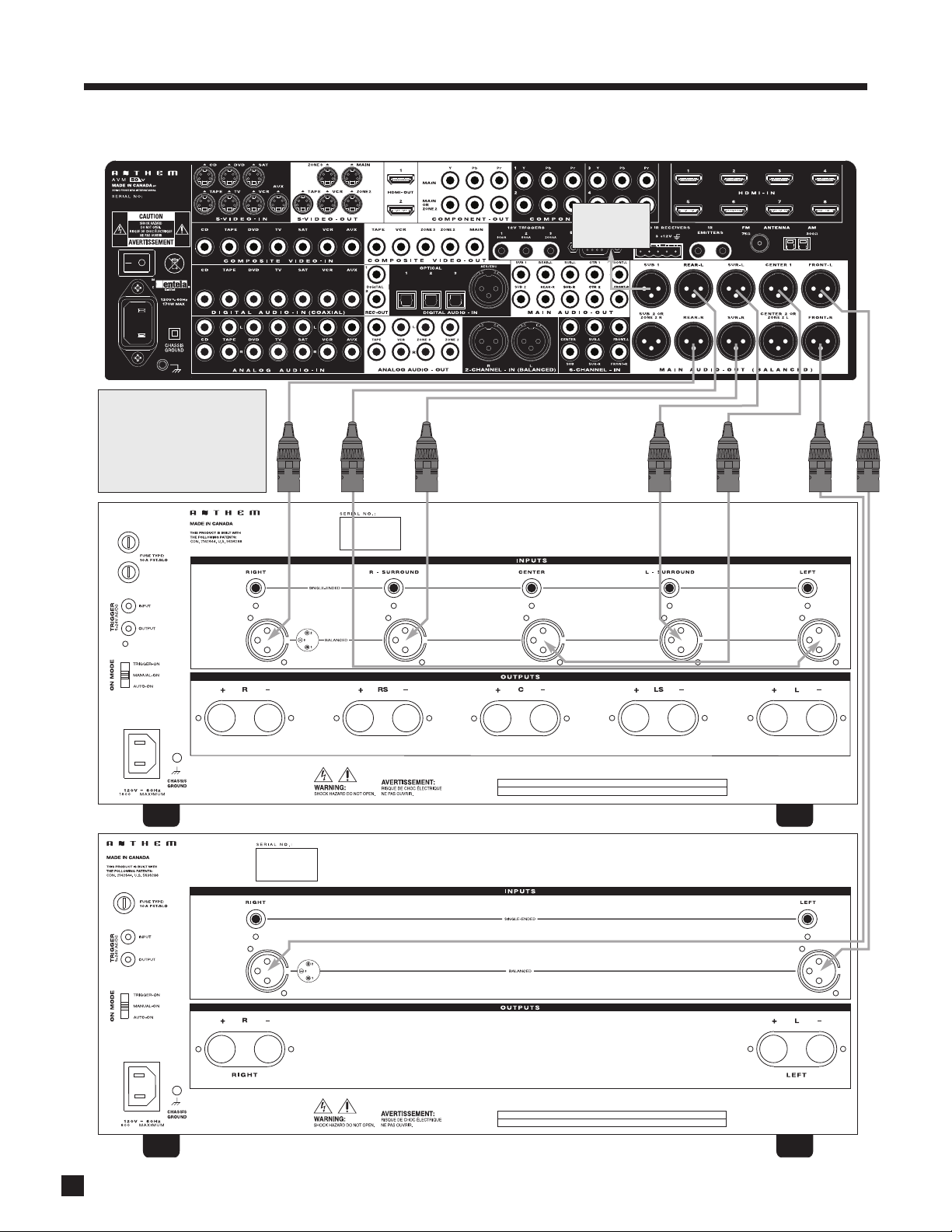
Example 3: Processor to amplifiers and subwoofer (Balanced connection shown, single-ended is similar)
To powered
subwoofer
Trigger Setup Suggestion:
If it is not necessary to have both
amplifiers turned on when stereo
sources are playing, set triggers
to turn on only the 2-channel
amplifier when a stereo source is
selected (see section 3.11).
VA
M C A 5 0
WARNING
RISK OF HAZARDOUS ENERGY! MAKE PROPER SPEAKER CONNECTIONS. SEE OPERATING MANUAL BEFORE USING.
WARNING
RISK OF HAZARDOUS ENERGY! MAKE PROPER SPEAKER CONNECTIONS. SEE OPERATING MANUAL BEFORE USING.
VA
M C A 2 0
15
3. SETUP
For optimum performance and enjoyment, your processor should be properly set up. This may appear like a
lot of work but keep in mind that most settings do not need to be changed from the factory ones.
The most important things are entering information about your display and speakers if the defaults do not
apply, the distance from each speaker to the listening area, balancing output levels to one another, and input
connections. The rest is preference – the surround mode presets, for example, should be set up after you
have played various sources and have decided which surround modes you like best.
For proper audio balance, menus involving test noises must be set up in the order that they appear.
Alternatively, most of the setup can be done on your personal computer through RS-232 connection and a
program from our web site, called Setup Editor. This can also save your configuration as a backup file. Setup
Editor cannot play test signals – calibration still has to be done through the setup menu.
HOW TO ENTER THE SETUP MENU
The setup menu can be accessed from MAIN and ZONE2. The on-screen display shows only in that path.
Test noises play only from MAIN.
Remote Control Front Panel
Make sure the appropriate control mode is set Make sure the appropriate path is selected then press
then press MENU or SUB/LFE for 3 seconds. and hold STATUS (Setup) for 3 seconds.
HOW TO NAVIGATE IN THE SETUP MENU
• Use the 56 buttons to scroll through menus.
• Press SELECT to choose a menu item.
• Use the 56 and 34 buttons to change settings.
• Press BACK to return to previous item or menu.
HOW TO EXIT FROM THE SETUP MENU
Press BACK as many times as necessary. Each time BACK is pressed the previous item or menu returns. The
menu will exit if not used for 5 minutes to prevent a burned-in on-screen image.

16
3. SETUP continued …
SETTING UP THE PROCESSOR
Upon entering the setup menu your display will show the menu below. Only 8 menu items can be displayed
at once – for clarity this manual shows each menu with all its items. On-screen display is recommended
although the front panel shows similar information, one item at a time. If the default video output settings do
not work with your display, use the front panel display to set video output. Setup menus are displayed
through MAIN HDMI and Component (processed) outputs, and MAIN and ZONE2 S-Video outputs, whereas
the 2-line status display and the video processing menu are displayed as follows:
MAIN on-screen display is available via HDMI1 output by default. On-screen display comes from HDMI2 and
Component (processed) if “Preferred” is changed to “Component” in menu 1 submenus. S-Video on-screen
display is available in both cases.
ZONE2 on-screen display is available via S-Video output.
To go to a submenu, highlight a menu item and press SELECT. Each on-screen menu also has a scrolling help
line at the bottom as shown above.
3.1 VIDEO OUTPUT
Highlighting VIDEO OUTPUT then pressing SELECT displays this menu:
ANTHEM AVM 50v SETUP
1. VIDEO OUTPUT
2. SET TIME / TIMERS
3. SPEAKER CONFIG
4. LISTENER POSITION
5. LEVEL CALIBRATION
6. SOURCE SETUP
7. MODE PRESETS
8. ANALOG INPUT LEVELS
9. ADC / AUDIO OUTPUT
10. VOLUMES / PATH NAMES
11. TRIGGER / IR / RS232
12. DISPLAYS / TIMEOUT
13. SAVE / LOAD SETTINGS
14. LOCKOUT / PASSWORDS
SELECT Enters Submenu
1. VIDEO OUTPUT
a. VIDEO OUT CONFIG 1
b. VIDEO OUT CONFIG 2
c. VIDEO OUT CONFIG 3
d. VIDEO OUT CONFIG 4

17
Video Output Configurations:
The AVM 50v allows four processed video output configurations, or Through (section 3.6). In most cases, only
one configuration is needed. The rest can be used to match the output refresh rate to source refresh rates,
i.e. 1080p24, 1080p50, and 1080p60 if
your display accepts these rates, or with a secondary display that needs
different settings – only one display can be used at a time in this case. Output assignment by source is
explained in section 3.6, and on-the-fly selection is explained at the end of section 4.11.
Once entering Configurations 2 through 4, the menu asks whether or not you want to use the same settings
as Configuration 1 – the factory default is Yes. If different settings are used, the output changes according
to the line that’s highlighted in the VIDEO OUTPUT menu. Highlighting VIDEO OUT CONFIG 1 in the VIDEO
OUTPUT menu then pressing SELECT displays this menu:
Items a. through g. pertain to MAIN output only.
Changes in this menu do not take place immediately to prevent loss of video output as you scroll through
settings. Once you leave this menu, it asks for confirmation – use the 34 buttons to change to Yes, then
press SELECT. To put a change into effect before leaving the menu, press SELECT then confirm.
If using both HDMI outputs and a conflict results when attempting to use two displays at the same time,
ensure that “automation” features that displays sometimes use to determine which of their HDMI inputs
have a signal are disabled. The input selection must remain on the one connected to the processor.
When two displays are connected and powered on, the EDID (handshake info) from the one connected
to HDMI1 is used in regard to Auto selections in the menu above, even if it results in output that the
display connected to HDMI2 does not support.
3. SETUP continued …
1a. VIDEO OUT CONFIG 1
a. S-VIDEO OSD: NTSC
b. PREFERRED: HDMI
c. RESL'N: 1280x720p60
d. COLOR SPACE: Auto
e. DATA: Auto
f. OUTPUT: Auto
g.LETTERBOX: Black
h. SYNC: Normal
i.COMPNT2 OUT: Passthru

18
3. SETUP continued …
How should I set my video sources to get the most out of video processing?
Where possible disable video processing in your sources so the AVM 50v’s advanced processing can
be used to its potential.
For standard DVD, set the player’s output to 480i/576i because if output is progressive you will be looking
at the player’s deinterlacing, not the AVM 50v’s. If the player does not allow 480i/576i HDMI output, using
480i/576i component
video output may be best. If the player can be set to put out both 480i (NTSC) and
576i (PAL) according to source, you can use that setting – the AVM 50v accepts both formats.
If your HD cable/satellite receiver has passthrough mode where output resolution follows each station’s
resolution, use it. If not, set the receiver’s output according to the HD channels that you watch most.
HD material on disc is natively 1080p24 or 1080i60 – if your player has a passthrough mode where output
resolution and refresh rate follow that of the source, you can use it with Configuration 1 resolution set
to, for example, 1920x1080p60 and Configuration 2 set to 1920x1080p24.
If your sources do not allow native (passthrough) video output, consider purchasing ones that do.
How should I set my display to get the most out of video processing?
If your display allows, set it to 1:1 pixel or dot-for-dot mode. The display’s stretch modes, including edge
cropping or overscan, should not be used if avoidable since they rescale the image unnecessarily.
S-Video On-Screen Display Format:
If using S-Video output use the 34 buttons to select NTSC or PAL, whichever matches your display. If your
display supports both formats, try NTSC first.
Preferred Video Output:
Use the 34 buttons to select Component or HDMI – the video will be optimized for that type. The other
output is disabled except to show menus. When Component is selected HDMI-only selections are not shown
.

19
3. SETUP continued …
Output Resolution:
Input from S-Video, Component, and HDMI is scaled to this resolution for Component and HDMI output. If
interlaced to progressive scan conversion is in effect, it is uncompromisingly pixel-adaptive even with 1080i,
and the same robust film mode detection applies as with standard-definition interlaced input.
Resolution is expressed as follows:
From the list below, use the setting that gives the best picture on your display. Other resolutions and refresh
rates are available through Live Video Settings Editor including computer monitor and custom resolutions.
• 720 x 480i or 480p at 60 Hz (480i is not applicable to DVI input on display)
• 720 x 576i or 576p at 50 Hz (576i is not applicable to DVI input on display)
• 1280 x 720p at 50 Hz or 60 Hz
• 1024 or 1280 or 1360 or 1366 x 768p at 60 Hz (DVI input on display is required)
• 1920 x 1080i at 50 or 60 Hz
• 1920 x 1080p at 24 Hz or 50 Hz* or 60 Hz*
• Custom (values must be entered through Custom Resolution Manager, a program on the ARC CD)
• Auto
§
*high-bandwidth cable is required
Color Space:
Set this to match your display type: HDTV (high definition TV), SDTV (standard definition), or Auto
§
.
Data Format:
Select YCbCr 4:2:2, YCbCr 4:4:4, Studio RGB, Extended RGB, or Auto
§
– whichever looks best. When YCbCr is
selected, the HDMI output uses YCbCr format and Component output uses YPbPr.
To determine whether Studio vs Extended RGB is the correct setting, compare shadow detail in dark scenes
or play the color bar test pattern in section 4.11 and look at the stripes in the lower right. If using YCbCr
output, compare detail around edges in colorful scenes to determine whether 4:2:2 vs 4:4:4 is best.
If colors look totally wrong with all sources, try all settings before contacting tech support
. If colors look
wrong only when certain sources are selected, see section 4.11.
§ Auto setting: Works with most displays but you may get a better result with manual selection.
Output:
Select Auto, 12-bit, 10-bit, or 8-bit. 12- and 10- bit formats are known as Deep Color. If your display supports
them but there is no picture due to insufficient bandwidth in the HDMI connection between processor and
display, and replacing it is not practical, try 8-bit or 10-bit setting (both are dithered to avoid or reduce
“banding” artifacts in the picture).
1920x1080p60
number of pixels across the screen
number of pixels or lines from top to bottom
scan type: p=progressive, i=interlaced
frames per second (Hz)

20
Letterbox:
When the source’s aspect ratio (the proportion of image width to height) does not match the display’s aspect
ratio and you want to preserve the original image’s proportions, the unused areas of the screen will be blank.
You can select the shade of these areas from ten levels between light gray and black. If you do not want
letterbox (bars on top/bottom) or pillarbox (sidebars) on your screen, see section 4.11.
Synchronization:
Try Inverted setting if the image via HDMI is not centered or does not show – typically needed only with some
older displays.
Component 2 Out:
The second Component video output can be configured in one of the following three ways or turned Off:
• MAIN output, processed (same signal as Component 1).
• MAIN output, passthrough – this bypasses the video processing and on-screen display is not
available. If a secondary display in the main room does not accept the format being fed to the main
display, use this setting.
• ZONE2 output – bypasses video processing and on-screen display not available.
3. SETUP continued …

21
3.2 SET TIME / TIMERS
The time and day, plus 6 different timers are set in this menu. The timers in the processor are like an alarm
clock, but allow two different timer settings for each of MAIN, ZONE2, and ZONE3.
To set Time and Day:
• Enter the setup menu. Go to SET TIME / TIMERS and press SELECT.
• Press the 6 button until you reach FORMAT.
• Use the 34 buttons and choose 12 Hr or 24 Hr.
• Press the 6 button to go to TIME.
• Press SELECT. “12” or the current hour will be highlighted in red.
• Use the Master Control Knob or the 56 buttons to set the current hour.
• Press the4 button. “00” or the current minutes will be highlighted.
• Use the Master Control Knob or the 56 buttons to set current minutes.
• Press BACK to return to the menu line.
• Press the 6 button to go to DAY then use the 34 buttons to set the current day.
All Timers:
This allows you to simultaneously “Enable” or “Disable” all Timers for MAIN, ZONE2, and ZONE3.
Highlighting SET MAIN TIMERS then pressing SELECT displays this menu:
2. SET TIME / TIMERS
a. FORMAT: 12 Hr
b. TIME: 12:00 AM
c. DAY: Sunday
d. ALL TIMERS: Disabled
e. SET MAIN TIMERS
f. SET ZONE2 TIMERS
g. SET ZONE3 TIMERS
2e. SET MAIN TIMERS
a. --- TIMER 1: Off ---
b. WEEKDAY ON: 8:00 AM
c. WEEKDAY OFF: 11:00 PM
d. WEEKEND ON: 10:00 AM
e. WEEKEND OFF: 11:00 PM
f. SOURCE: Last Stn
g. ON-VOLUME: -35.0 dB
h. --- TIMER 2: Off ---
i. WEEKDAY ON: 8:00 AM
j. WEEKDAY OFF: 11:00 PM
k. WEEKEND ON: 10:00 AM
l. WEEKEND OFF: 11:00 PM
m. SOURCE: Last Stn
n. ON-VOLUME: -35.0 dB
3. SETUP continued …

22
3. SETUP continued …
Timer Options:
There are two Timers for Main and each Zone to allow greater flexibility. You can set week and weekend
on/off times twice – once for the morning and again for the evening, for example.
Using the 34 buttons, TIMER 1 and TIMER 2 choices are:
• Off – Timer is disabled.
• Week – Timer operates from Monday to Friday.
• Wkend – Timer operates on Saturday and Sunday.
• Wk+Wkend – Timer operates every day.
On and Off Times:
Auto-on/off times are entered for:
T1 or T2 WEEKDAY ON: Sets the Monday to Friday turn-on time.
T1 or T2 WEEKDAY OFF: Sets the Monday to Friday turn-off time.
T1 or T2 WEEKEND ON: Sets the Saturday and Sunday turn-on time.
T1 or T2 WEEKEND OFF: Sets the Saturday and Sunday turn-off time.
Timers may also be set to only turn on or only turn off (see Example 2) – this way, the processor can be set
to turn on automatically, and it won’t turn off until you turn it off manually.
If the processor is already on, Timer On settings are ignored to ensure that source and volume are not
changed while in use.
Source:
Select what you want to be playing when a Timer turns the power on – any source, any preset FM • AM
station, or Last Stn (the tuner setting when processor was turned off). Be sure that the source and the power
amplifier are turned on or will be on at the Timer turn-on time. If your components have trigger inputs, you
can set a processor trigger to turn them on (see section 3.11).
On-Volume:
Sets the volume that will play when a Timer turns the power on. The volume increases slowly when a Timer
turns the power on.
Loading...