


 Loading...
AVM 20
OPERATING MANUAL
UPDATES: www.anthemAV.com
S O F T W A R E V E R S I O N 2 . 1 x


 ™
™

SAFETY PRECAUTIONS
READ THIS SECTION CAREFULLY BEFORE PROCEEDING!
WARNING
RISK OF ELECTRIC SHOCK
DO NOT OPEN
WARNING: TO REDUCE THE RISK OF ELECTRIC SHOCK,
DO NOT REMOVE COVER (OR BACK). NO USER-
SERVICEABLE PARTS INSIDE. REFER SERVICING TO
QUALIFIED SERVICE PERSONNEL.
The lightning flash with arrowpoint within an equilateral triangle warns of the presence of uninsulated “dangerous voltage” within the product’s enclosure that may be of sufficient magnitude to constitute a risk of electric shock to persons.
The exclamation point within an equilateral triangle warns users of the presence of important operating and maintenance (servicing) instructions in the literature accompanying the appliance.
WARNING: TO REDUCE THE RISK OF FIRE OR ELECTRIC SHOCK, DO NOT EXPOSE THIS PRODUCT TO RAIN OR MOISTURE.
CAUTION: TO PREVENT ELECTRIC SHOCK, MATCH WIDE BLADE OF PLUG TO WIDE SLOT, FULLY INSERT.
CAUTION: FOR CONTINUED PROTECTION AGAINST RISK OF FIRE, REPLACE THE FUSE ONLY WITH THE SAME AMPERAGE AND VOLTAGE TYPE. REFER REPLACEMENT TO QUALIFIED SERVICE PERSONNEL.
WARNING: UNIT MAY BECOME HOT. ALWAYS PROVIDE ADEQUATE VENTILATION TO ALLOW FOR COOLING. DO NOT PLACE NEAR A HEAT SOURCE, OR IN SPACES THAT CAN RESTRICT VENTILATION.
IMPORTANT SAFETY INSTRUCTIONS
1.Read Instructions – All the safety and operating instructions should be read before the product is operated.
2.Retain Instructions – The safety and operating instructions should be retained for future reference.
3.Heed Warnings – All warnings on the product and in the operating instructions should be adhered to.
4.Follow Instructions – All operating and use instructions should be followed.
5.Cleaning – Unplug this product from the wall outlet before cleaning. Do not use liquid cleaners or aerosol cleaners. Use a damp, soft cloth for cleaning.
6.Water and Moisture – Do not use this product near water – for example, near a bath tub, wash bowl, kitchen sink, or laundry tub; in a wet basement; or near a swimming pool; and the like.
7.Accessories – Do not place this product on an unstable cart, stand, tripod, bracket, or table. The product may fall, causing serious injury to a child or adult, and serious damage to the product. Use only with a cart, stand, tripod, bracket, or table recommended by the manufacturer, or sold with the product. Any mounting of the product should follow manufacturer’s instructions, and should use a mounting accessory recommended by the manufacturer.

8.Ventilation – Slots and openings in the cabinet are provided for ventilation and to ensure reliable operation of the product and to protect it from overheating, and these openings must not be blocked or covered. The openings should never be blocked by placing the product on a bed, sofa, rug, or other similar surface. This product should not be placed in a built-in installation such as a bookcase or rack unless proper ventilation is provided or the manufacturer’s instructions have been adhered to.
9.Power Sources – This product should be operated only from the type of power source indicated on the marking label. If you are not sure of the type of power supply to your home, consult your product dealer or local power company. For products intended to operate from battery power, or other sources, refer to the operating instructions.
10.Grounding and Polarization – This product may be equipped with a polarized alternating-current line plug (a plug having one blade wider than the other). This plug will fit into the power outlet only one way. This is a safety feature. If you are unable to insert the plug fully into the outlet, try reversing the plug. If the plug should still fail to fit, contact your electrician to replace your obsolete outlet. Do not defeat the safety purpose of the polarized plug.
11.Power-cord Protection – Power-supply cords should be routed so that they are not likely to be walked on or pinched by items placed upon or against them, paying particular attention to cords at plugs, convenience receptacles, and the point where they exit from the product.
12.Outdoor Antenna Grounding – If an outside antenna or cable system is connected to the product, be sure the antenna or cable system is grounded so as to provide some protection against voltage surges and built-up static charges. Article 810 of the National Electrical Code, ANSI/NFPA 70, provides information with regard to the proper grounding of the mast and supporting structure, grounding of the lead-in wire to an antenna– discharge unit, size of grounding conductors, location of antenna-discharge unit, connection to grounding electrodes, and requirements for the grounding electrode.
Antenna Lead-In Wire
Ground Clamp |
|
|
Antenna-Discharge Unit |
|
(NEC Section 810-20) |
Electrical Service |
Grounding Conductors |
Equiptment |
(NEC Section 810-21) |
|
Ground Clamps |
|
Power Service Grounding |
|
Electronic System |
NEC-National Electrical Code |
(NEC ART 250. Part H) |
|
|
S2898A |
|
13.Lightning – For added protection for this product during a lightning storm, or when it is left unattended and unused for long periods of time, unplug it from the wall outlet and disconnect the antenna or cable systems. This will prevent damage to the product due to lightning and power-line surges.
14.Power Lines – An outside antenna system should not be located in the vicinity of overhead power lines or other electric light or power circuits, or where it can fall into such power lines or circuits. When installing an outside antenna system, extreme care should be taken to keep from touching such power lines or circuits as contact with them might be fatal.
15.Overloading – Do not overload wall outlets, extension cords, or integral convenience receptacles as this can result in a risk of fire or electric shock.
16.Object and Liquid Entry – Never push objects of any kind through openings as they may touch dangerous voltage points or short-out parts that could result in a fire or electric shock. Never spill liquid of any kind on this product.
17.Servicing – Do not attempt to service this product yourself, as opening or removing covers may expose you to dangerous voltage or other hazards. Refer all servicing to qualified service personnel.
18.Damage Requiring Service – Unplug this product from the wall outlet and refer servicing to qualified personnel under the following conditions:
•When power-supply cord or plug is damaged.
•If liquid has been spilled, or objects have fallen into the product.
•If the product has been exposed to rain or water.
•If the product does not operate normally by following the operating instructions. Adjust only those controls that are covered by the operating instructions as an improper adjustment of other controls may result in damage and will require extensive work by a qualified technician to restore the product to its normal operation.
•If the product has been dropped or damaged in any way.
•If the product exhibits a distinct change in performance – this indicates a need for service.
19.Replacement Parts – When replacement parts are required, be sure the technician has used replacement parts specified by the manufacturer or have the same characteristics as the original part. Unauthorized substitutions may result in fire, electric shock, or other hazards.
20.Safety Check – Upon completion of any service or repairs to this product, ask the service technician to perform safety checks to determine that the product is in proper operating condition.
21.Heat – The product should be situated away from heat sources such as radiators, heat registers, stoves, or other products (including amplifiers) that produce heat.
Copyright© Anthem™/Sonic Frontiers International. All rights reserved. The information contained herein may not be reproduced in whole or in part without our express written permission.
ANTHEM™ is a trademark of Sonic Frontiers International. All other trademarks are the property of their respective owners.
Anthem™/Sonic Frontiers International reserves the right to change specifications and/or features without notice as design improvements are incorporated.
Motorola name and logo are registered trademarks of Motorola, Inc.
PHASTLINK™ is a trade mark of PHAST Corporation.
Manufactured under license from Dolby Laboratories. “Dolby”, “Pro Logic”, “AC-3”, “Surround EX”, and the double-D symbol are trademarks of Dolby Laboratories.
“DTS”, “DTS-ES Extended Surround”, “DTS 96/24”, and “Neo:6” are trademarks of Digital Theater Systems, Inc.
Manufactured under license from THX Ltd. U.S. patent numbers 5,043,970; 5,189,703; and/or 5,222,059. European patent number 0323830. Other U.S. and foreign patents pending. Ultra2 and THX are trademarks or registered trademarks of THX Ltd. Lucasfilm is a trademark of Lucasfilm Ltd. Surround EX is a trademark of Dolby Laboratories. Used under authorization.

TABLE of CONTENTS
|
|
SECTION |
|
|
PAGE |
|
|
1. INTRODUCTION |
|
1 |
|
|
|
|
|||
1 |
Receiving and Unpacking the AVM 20 . . . . . . . . . . . . . . . . . . . . . . . . . . . . . . . . . . . . . . . . . . . . . |
. . . . 1 |
|||
1.1 |
Packing List . . . . . . . . . . . . . . . . . . . . . . . . . . . . . . . . . . . . . . . . . . . . . . . . . . . . . . . . . . . . . . . . . . . . |
. . . . 1 |
|||
1.2 |
Important Safety Instructions . . . . . . . . . . . . . . . . . . . . . . . . . . . . . . . . . . . . . . . . . . . . . . . . . . . . . . |
. . . 1 |
|||
|
|
|
1.2.1 Before Operating Your AVM 20 |
1 |
|
|
|
|
1.2.2 |
Supply Power Requirements |
2 |
|
|
|
1.2.3 |
In-Use Notices |
2 |
1.3 |
Packing Materials . . . . . . . . . . . . . . . . . . . . . . . . . . . . . . . . . . . . . . . . . . . . . . . . . . . . . . . . . . . . . . . |
. . . 2 |
|||
|
|
2. QUICK START |
|
|
3 |
|
|
|
|
||
|
2.1 |
Quick Start Guide . . . . . . . . . . . . . . . . . . . . . . . . . . . . . . . . . . . . . . . . . . . . . . . . . . . . . . . . . . . . . . . . |
. . . 3 |
||
2.2 |
Connector Diagrams and Descriptions . . . . . . . . . . . . . . . . . . . . . . . . . . . . . . . . . . . . . . . . . . . . . |
. . . 4 |
|||
|
|
|
2.2.1 CD Player to AVM 20 |
5 |
|
|
|
|
2.2.2 DVD Player and TV to AVM 20 |
6 |
|
|
|
|
2.2.3 VCR and TV to AVM 20 |
7 |
|
|
|
|
2.2.4 AVM 20 to Amplifier and Powered Subwoofer (RCA) |
8 |
|
|
|
|
2.2.5 AVM 20 to Amplifiers and Powered Subwoofer (XLR) |
9 |
|
2.3 |
Speaker Placement . . . . . . . . . . . . . . . . . . . . . . . . . . . . . . . . . . . . . . . . . . . . . . . . . . . . . . . . . . . . . |
. . 10 |
|||
|
|
3. PANELS / DISPLAYS / REMOTE LAYOUT |
11 |
||
|
|
||||
3.1 |
Front Panel Layout . . . . . . . . . . . . . . . . . . . . . . . . . . . . . . . . . . . . . . . . . . . . . . . . . . . . . . . . . . . . . . . |
. . 11 |
|||
3.2 |
Front Panel Display . . . . . . . . . . . . . . . . . . . . . . . . . . . . . . . . . . . . . . . . . . . . . . . . . . . . . . . . . . . . . . |
. . 12 |
|||
3.3 |
Rear Panel Layout . . . . . . . . . . . . . . . . . . . . . . . . . . . . . . . . . . . . . . . . . . . . . . . . . . . . . . . . . . . . . . . . |
. . 13 |
|||
3.4 |
Remote Control Layout . . . . . . . . . . . . . . . . . . . . . . . . . . . . . . . . . . . . . . . . . . . . . . . . . . . . . . . . . . . |
. . 14 |
|||
|
|
4. CONNECTIONS |
|
|
15 |
|
|
|
|
||
4.1 |
Connecting Power To The AVM 20 . . . . . . . . . . . . . . . . . . . . . . . . . . . . . . . . . . . . . . . . . . . . . . . . . |
. . 15 |
|||
4.2 |
Audio Connections . . . . . . . . . . . . . . . . . . . . . . . . . . . . . . . . . . . . . . . . . . . . . . . . . . . . . . . . . . . . . . |
. . 15 |
|||
|
|
|
4.2.1 Digital Audio Inputs and Outputs . . . . . . . . . . . . . . . . . . . . . . . . . . . . . . . . . . . . . . . . . |
. . 15 |
|
|
|
|
4.2.2 |
Analog Audio Inputs |
15 |
|
|
|
4.2.3 Left / Right Analog Audio Inputs |
16 |
|
|
|
|
4.2.4 2-Ch Balanced and 6-Ch Single-Ended Audio Inputs |
16 |
|
|
|
|
4.2.5 |
Analog Audio Outputs |
16 |
4.3 |
Video Connections . . . . . . . . . . . . . . . . . . . . . . . . . . . . . . . . . . . . . . . . . . . . . . . . . . . . . . . . . . . . . . . |
. . 17 |
|||
|
|
|
|
Composite Video |
17 |
|
|
|
|
S-Video |
17 |
|
|
|
|
Component Video |
17 |
4.4 |
Powered I.R. (Infra Red) Receivers. . . . . . . . . . . . . . . . . . . . . . . . . . . . . . . . . . . . . . . . . . . . . . . . . . |
. . 19 |
|||
4.5 |
I.R. (Infra Red) Emitters. . . . . . . . . . . . . . . . . . . . . . . . . . . . . . . . . . . . . . . . . . . . . . . . . . . . . . . . . . . . |
. . 19 |
|||
4.6 |
Relay Triggers . . . . . . . . . . . . . . . . . . . . . . . . . . . . . . . . . . . . . . . . . . . . . . . . . . . . . . . . . . . . . . . . . . . |
. . 19 |
|||
4.7 |
FM•AM Antennas . . . . . . . . . . . . . . . . . . . . . . . . . . . . . . . . . . . . . . . . . . . . . . . . . . . . . . . . . . . . . . . . |
. . 19 |
|||
|
5. FRONT PANEL OPERATION |
|
20 |
|
|
5.1 |
. . . . . . . . . . . . . . . . . . . . . . . . . . . . . . . . . . . . . . . . . . . . . . . . . . . . . . . . . . . . . . . . . . . .Power On / Off |
20 |
|
|
5.2 |
Path Selection . . . . . . . . . . . . . . . . . . . . . . . . . . . . . . . . . . . . . . . . . . . . . . . . . . . . . . . . . . . . . . . . . . . . . |
20 |
|
|
|
5.2.1 |
Copying the MAIN Path to ZONE2, ZONE3, or RECORD |
21 |
|
|
|
Down-Mixing to 2-Channel Stereo |
21 |
|
5.3 |
Master Control Knob. . . . . . . . . . . . . . . . . . . . . . . . . . . . . . . . . . . . . . . . . . . . . . . . . . . . . . . . . . . . . . . . |
21 |
|
|
5.4 |
Source Selection. . . . . . . . . . . . . . . . . . . . . . . . . . . . . . . . . . . . . . . . . . . . . . . . . . . . . . . . . . . . . . . . . . . |
21 |
|
|
|
5.4.1 |
6-Channel S/E Input |
21 |
|
|
5.4.2 |
FM•AM Tuner |
22 |
|
|
|
Manual Tuning |
22 |
|
|
|
Automatic Tuning |
22 |
|
|
|
Presets |
22 |
|
|
|
ST / HiB / M |
22 |
|
|
5.4.3 |
Simulcast |
22 |
|
5.5 |
Volume Control . . . . . . . . . . . . . . . . . . . . . . . . . . . . . . . . . . . . . . . . . . . . . . . . . . . . . . . . . . . . . . . . . . . . |
23 |
|
|
|
|
Dialog Normalization |
23 |
|
|
|
Mute |
23 |
|
5.6 |
Surround Mode Level . . . . . . . . . . . . . . . . . . . . . . . . . . . . . . . . . . . . . . . . . . . . . . . . . . . . . . . . . . . . . . . |
23 |
|
|
5.7 |
Bass / Treble / Balance . . . . . . . . . . . . . . . . . . . . . . . . . . . . . . . . . . . . . . . . . . . . . . . . . . . . . . . . . . . . . |
24 |
|
|
|
|
Tone Bypass |
24 |
|
5.8 |
Surround Modes . . . . . . . . . . . . . . . . . . . . . . . . . . . . . . . . . . . . . . . . . . . . . . . . . . . . . . . . . . . . . . . . . . . |
24 |
|
|
|
5.8.1 |
AnthemLogic™ |
25 |
|
|
5.8.2 |
Dolby Digital-2.0 |
25 |
|
|
5.8.3 |
Surround Modes for Stereo Source Material |
26 |
|
|
5.8.4 |
Dolby Digital EX |
27 |
|
|
5.8.5 |
DTS-ES |
27 |
|
|
5.8.6 |
THX Ultra2 / THX Surround EX |
27 |
|
|
5.8.7 |
Modes and THX Operation for Stereo Program Material |
31 |
|
|
5.8.8 |
Modes and THX Operation for Dolby Digital 5.1 Program Material |
32 |
|
|
5.8.9 |
Modes and THX Operation for DTS program Material |
33 |
|
|
5.8.10 |
Dynamics |
34 |
|
5.9 |
Front Panel Display. . . . . . . . . . . . . . . . . . . . . . . . . . . . . . . . . . . . . . . . . . . . . . . . . . . . . . . . . . . . . . . . . |
34 |
|
|
5.10 |
Status / Setup. . . . . . . . . . . . . . . . . . . . . . . . . . . . . . . . . . . . . . . . . . . . . . . . . . . . . . . . . . . . . . . . . . . . . . |
34 |
|
|
6. REMOTE CONTROL OPERATION |
35 |
||
|
||||
|
6.1 |
Powering the AVM 20 ON and OFF . . . . . . . . . . . . . . . . . . . . . . . . . . . . . . . . . . . . . . . . . . . . . . . . . . . . |
35 |
|
|
6.2 |
Path Selection . . . . . . . . . . . . . . . . . . . . . . . . . . . . . . . . . . . . . . . . . . . . . . . . . . . . . . . . . . . . . . . . . . . . . |
36 |
|
|
|
6.2.1 |
Copying the MAIN Path to ZONE2, ZONE3, or RECORD |
36 |
|
6.3 |
Source Selection. . . . . . . . . . . . . . . . . . . . . . . . . . . . . . . . . . . . . . . . . . . . . . . . . . . . . . . . . . . . . . . . . . . |
36 |
|
|
|
6.3.1 |
Source Seek |
36 |
|
6.4 |
Direct FM•AM Station Entry . . . . . . . . . . . . . . . . . . . . . . . . . . . . . . . . . . . . . . . . . . . . . . . . . . . . . . . . . |
36 |
|
|
6.5 |
Sleep Timer . . . . . . . . . . . . . . . . . . . . . . . . . . . . . . . . . . . . . . . . . . . . . . . . . . . . . . . . . . . . . . . . . . . . . . . |
36 |
|
|
6.6 |
Enable / Disable Auto-On Timers . . . . . . . . . . . . . . . . . . . . . . . . . . . . . . . . . . . . . . . . . . . . . . . . . . . . . |
36 |
|
|
6.7 |
Audio Group Delay . . . . . . . . . . . . . . . . . . . . . . . . . . . . . . . . . . . . . . . . . . . . . . . . . . . . . . . . . . . . . . . . . |
37 |
|
|
6.8 |
Controlling Other Components . . . . . . . . . . . . . . . . . . . . . . . . . . . . . . . . . . . . . . . . . |
. . . . . . . . . . . . . . 37 |
||
|
|
|
6.8.1 |
Entering Manufacturer’s Codes |
37 |
|
|
|
6.8.2 |
Searching For a Code |
37 |
|
|
|
6.8.3 |
Volume Lock |
37 |
|
|
|
6.8.4 |
Learning Function |
38 |
|
|
|
|
Limitations on Learning |
38 |
|
|
|
|
Teaching a Key |
39 |
|
|
|
|
Deleting a Learned Command from a Key |
39 |
|
6.9 |
Controlling the AVM 20 with Aftermarket Remotes . . . . . . . . . . . . . . . . . . . . . . . . . |
. . . . . . . . . . . . . 39 |
||
|
|
7. SETUP MENU |
|
|
40 |
|
|
|
|
||
|
7.1 |
How to Enter the Setup Menu . . . . . . . . . . . . . . . . . . . . . . . . . . . . . . . . . . . . . . . . . . . |
. . . . . . . . . . . . . 40 |
||
|
7.2 |
How to Navigate in the Setup Menu . . . . . . . . . . . . . . . . . . . . . . . . . . . . . . . . . . . . . |
. . . . . . . . . . . . . 40 |
||
|
7.3 |
How to Exit the Setup Menu . . . . . . . . . . . . . . . . . . . . . . . . . . . . . . . . . . . . . . . . . . . . |
. . . . . . . . . . . . . 40 |
||
|
7.4 |
Setting Up the AVM 20 . . . . . . . . . . . . . . . . . . . . . . . . . . . . . . . . . . . . . . . . . . . . . . |
. . . . . . . . . . . . . 41 |
||
|
|
|
7.4.1 |
Set Time / Timers |
41 |
|
|
|
7.4.2 |
Speaker Configuration |
42 |
|
|
|
7.4.3 |
Listener Position |
49 |
|
|
|
7.4.4 |
Speaker Level Calibration |
50 |
|
|
|
7.4.5 |
Source Setup / Presets |
52 |
|
|
|
7.4.6 |
Adjust Input Levels |
56 |
|
|
|
7.4.7 |
A-D / Audio-Out Format |
57 |
|
|
|
7.4.8 |
Volumes / Rename Paths |
58 |
|
|
|
7.4.9 |
Triggers / IR / RS-232 |
59 |
|
|
|
7.4.10 |
Displays / Timeout |
61 |
|
|
|
7.4.11 |
Save / Restore Settings |
63 |
|
|
|
7.4.12 |
Lockout / Passwords |
65 |
|
|
8. SOFTWARE UPDATING |
|
66 |
|
|
|
|
|||
|
8.1 |
Software Version Identification . . . . . . . . . . . . . . . . . . . . . . . . . . . . . . . . . . . . . . . . |
. . . . . . . . . . . . . 66 |
||
|
8.2 |
Software Updating Via Your Dealer . . . . . . . . . . . . . . . . . . . . . . . . . . . . . . . . . . . . . . |
. . . . . . . . . . . . . 66 |
||
|
8.3 |
Software Updating Via Your Computer and the Internet . . . . . . . . . . . . . . . . . . . . . |
. . . . . . . . . . . . . 66 |
||
|
Appendix A – Remote Control Codes |
68 |
|||
|
Specifications |
|
|
71 |
|
|
Warranty |
|
|
74 |
|
|
Big Pictures of Front and Rear Panels |
Inside Back Cover |
|||

1. INTRODUCTION
Thank you for purchasing the Anthem AVM 20 Preamplifier • Processor • Tuner.
Anthem Electronics has been manufacturing high-quality, high-end audio equipment for over a decade. In that time, Anthem has built an enviable reputation for products that can recreate the passion a music lover experiences when attending a live musical performance, or the thrilling sound a movie buff experiences in the very best movie theaters. Anthem equipment allows audiophiles to almost “be there” each and every time they sit and enjoy music or home theater in the comfort of their home. Anthem provides all this with the highest level of craftsmanship, sophisticated circuit designs, superior quality parts and materials, modern intuitive ergonomics, and stylish industrial design.
Although Anthem products sound great “right out of the carton”, they will sound even better after they are thermally stabilized. We therefore recommend that you operate this product for a period of time before doing any critical listening.
The AVM 20 is a state-of-the-art four path A/V Preamplifier / Surround Sound Processor, with built-in FM • AM Tuner. It is designed to provide high-end sound and video for both music, home theater, and multi-room applications.
1 RECEIVING AND UNPACKING THE AVM 20
The AVM 20 is shipped in a reinforced shipping box. Please keep this box for any future shipment. Check that you have received everything in the Packing List below and report any discrepancies to your dealer as soon as possible. Keep the invoice that you received from your authorized Anthem dealer at time of purchase – without it, service cannot be given under warranty.
1.1PACKING LIST
•AVM 20
•Powered IR Terminal Block (on rear panel)
•Remote Control
•2 ‘AA’ Batteries
•Power Cord
•FM Antenna
•75-ohm to 300-ohm FM Antenna Adapter
•AM Loop Antenna
•Operating Manual
1.2IMPORTANT SAFETY INSTRUCTIONS
•The Front Panel power switches are secondary only; they do not disconnect the AVM 20 from the AC power line. Line voltage is switched off through the rear panel power switch.
•Failing to comply with any safety instruction, precaution, or warning in this Operating Manual is in direct violation of the standards of design, manufacture, and intended use of the product.
•Anthem, Sonic Frontiers International, our agents, and any related party assume no liability whatsoever for the user’s failure to comply with any or all of these requirements.
1.2.1BEFORE OPERATING YOUR AVM 20
•Do not connect power to the AVM 20 if there are signs of damage to any part of its exterior.
•Install the AVM 20 in a stable location. Do not mount to a wall or from a ceiling.
•Allow six or more inches of unobstructed air space above the ventilation slots in the top cover of the AVM 20. Do not block any ventilation openings. Do not obstruct bottom vents by removing the rubber feet or operating the AVM 20 directly on a carpet, sofa, or similar surface.
1

1. INTRODUCTION continued …
1.2.2 SUPPLY POWER REQUIREMENTS
The AVM 20 operates from a single phase AC power source that supplies between 105V and 130V at a frequency of 60 Hz. It cannot be changed from 120V to 240V operation.
DO NOT USE A POWER LINE CONDITIONER:
•Some Power Line Conditioners are incompatible with the AVM 20 and may cause the AVM 20’s AC line fuses to blow.
•One is not required because the AVM 20’s power supply has power line filtering and voltage regulation built in.
1.2.3IN-USE NOTICES
•Use only the power supply cord with double insulation as supplied.
•Disconnect the AVM 20’s power cord before connecting or disconnecting any components.
•Fuses are not a user serviceable item (see specification section).
•Do not remove the top cover.
•Do not alter or modify the AVM 20 in any way.
1.3PACKING MATERIALS
Retain the shipping box and all packing material. They are custom designed to prevent shipping damage. Do not ship or transport the AVM 20 in anything other than the original box and packing material.
2

2. QUICK START
The AVM 20 is a very sophisticated component, providing a multitude of features and connection options, while providing easy intuitive setup and operation. With your AVM 20 in front of you, browse through the illustrations in this section to see several quick system hookup options. It’s as simple as following the lines in the connection diagrams to and from each component.
All of these quick system hookup examples work with the Factory Default settings; none require the Setup Menu. Just ‘plug & play’! However, references to the Setup Menu section are included to make you aware of the tremendous versatility of the AVM 20.
For the best sound possible you will still have to calibrate your system in the Setup as outlined in section 7. Please do not overlook this important system calibration procedure.
2.1QUICK START GUIDE – Before you start, make sure all components are unplugged.
To connect a CD player, DVD player, TV, VCR, amplifier(s), and powered subwoofer to the AVM 20:
Note: For this Quick start setup section, you will only need to connect either the Composite or S-Video connections referred to in the following diagrams. Use the S-Video connections wherever possible for the better video quality.
• CD Player to AVM 20 – see diagram in section 2.2.1
Connect the L/R audio output of the CD player to Analog Audio-In/CD on the AVM 20.
•DVD Player to AVM 20 – see diagram in section 2.2.2
Video: Connect the player’s composite video out to Composite Video-In/DVD on the AVM 20. Audio: Connect the player’s digital audio output to Digital Audio-In/DVD on the AVM 20.
•AVM 20 to TV – see diagrams in sections 2.2.2 and 2.2.3
Video: Connect Composite Video-Out/MAIN on the AVM 20 to the TV’s composite video input. Audio: Connect the L/R audio output of the TV to Analog Audio-In/TV on the AVM 20.
•VCR to AVM 20 – see diagram in section 2.2.3
Video: Connect the VCR’s composite video output to Composite Video-In/VCR on the AVM 20. To Record: Connect Composite Video-Out/VCR to the VCR’s composite video input.
Audio: Connect the L/R audio output of the VCR to Analog Audio-In/VCR on the AVM 20. To Record: Connect Analog Audio-Out/VCR to the L/R audio input of the VCR.
•AVM 20 to Amplifier(s) – see diagrams in sections 2.2.4 and 2.2.5
From the AVM 20, connect Front-L, Front-R, Ctr1, Sur-L, Sur-R, Rear-L, and Rear-R Analog Audio-Out to the Front-L, Front-R, Center, Sur-L, Sur-R, Rear-L, and Rear-R inputs of the power amplifier(s). Follow the amplifier’s operating manual for connecting the speakers.
• AVM 20 to Powered Subwoofer – see diagrams in sections 2.2.4 and 2.2.5 Connect Analog Audio-Out/Sub1 to the subwoofer’s line/low level input.
Reconnect the power to all components and turn them on. To turn on the AVM 20, move the switch on the rear panel to the ‘on’ position and then press the POWER – MAIN button on the front panel.
3
2. QUICK START continued …
To Watch a DVD:
•Press DVD Source on the front panel of the AVM 20.
•Select the TV input that corresponds to the one that the AVM 20’s Composite Video-Out/MAIN is plugged into.
•Place a DVD into the DVD player and press play. You should see the picture on your TV and hear sound from your speakers. Adjust volume using the Master Control Knob on the AVM 20.
To Watch a Video Tape:
•Press VCR Source on the front panel of the AVM 20.
•With your TV’s remote control, select the input that the AVM 20’s Composite Video-Out/MAIN is plugged into.
•Insert a tape into the VCR and press play. You should see the picture on your TV and hear sound from your speakers. Use the AVM 20 Master Control Knob on the front panel to adjust volume.
To Listen to a CD:
•Press CD Source on the front panel of the AVM 20.
•Place a CD into the CD player and press play. You should hear music coming from your speakers. Use the AVM 20 Master Control Knob on the front panel to adjust volume.
Note about Digital and Analog Inputs:
•You can change any input to Digital or Analog. Digital inputs use the AVM 20’s high-end digital to analog converters and can be changed from RCA to Toslink or XLR connection. Analog inputs can be set to Digital Signal Processing for bass management, bass/treble control, time alignment, and surround modes, or Direct to bypass all digital stages. Auto-Dig uses the digital connection if a digital signal is sensed, and automatically switches to analog connection if there is no digital signal. For more information see sections 4.2.1 and 7.4.5.
Note about Your Speakers:
•The AVM 20 allows you to enter information about how many speakers you have in your system, as well as their relative size, type, and distance from your listening position. This speaker setup information is important in directing audio signals optimally, ensuring you get the best quality sound from your system – see sections 7.4.2, 7.4.3, and 7.4.4.
2.2CONNECTOR DIAGRAMS AND DESCRIPTIONS
The following pages of illustrations contain a variety of standard cable/connectors that are used to connect components to your AVM 20. The various types, and what they are used for, are shown here:
RCA Black or |
RCA Red |
RCA Yellow |
1/4” Stereo |
3.5mm |
|
5-Pin |
Toslink |
XLR Female |
XLR Male |
||||||||||||||||||||||||||
|
White |
Mini (Mono) |
Mini DIN |
(connects to output) |
(connects to input) |
||||||||||||||||||||||||||||||
|
|
|
|
|
|
|
|
|
|
|
|
|
|
|
|
||||||||||||||||||||
|
|
|
|
|
|
|
|
|
|
|
|
|
|
|
|
|
|
|
|
|
|
|
|
|
|
|
|
|
|
|
|
|
|
|
|
|
|
|
|
|
|
|
|
|
|
|
|
|
|
|
|
|
|
|
|
|
|
|
|
|
|
|
|
|
|
|
|
|
|
|
|
|
|
|
|
|
|
|
|
|
|
|
|
|
|
|
|
|
|
|
|
|
|
|
|
|
|
|
|
|
|
|
|
|
|
|
|
|
|
|
|
|
|
|
|
|
|
|
|
|
|
|
|
|
|
|
|
|
|
|
|
|
|
|
|
|
|
|
|
|
|
|
|
|
|
|
|
|
|
|
|
|
|
|
|
|
|
|
|
|
|
|
|
|
|
|
|
|
|
|
|
|
|
|
|
|
|
|
|
|
|
|
|
|
|
|
|
|
|
|
|
|
|
|
|
|
|
|
|
|
|
|
|
|
|
|
|
|
|
|
|
|
|
|
|
|
|
|
|
|
|
|
|
|
|
|
|
|
|
|
|
|
|
|
|
|
|
|
|
|
|
|
|
|
|
|
|
|
|
|
|
|
|
|
|
|
|
|
|
|
|
|
|
|
|
|
|
|
|
|
|
|
|
|
|
|
|
|
|
|
|
|
|
|
|
|
|
|
|
|
|
|
|
|
|
|
|
|
|
|
|
|
|
|
|
|
|
|
|
|
|
|
|
|
|
|
|
|
|
|
|
|
|
|
|
|
|
|
|
|
|
|
|
|
|
|
|
|
|
|
|
|
|
|
|
|
|
|
|
|
|
|
|
|
|
|
|
|
|
|
|
|
|
|
|
|
|
|
|
|
|
|
|
|
|
|
|
|
|
|
|
|
|
|
|
|
|
|
|
|
|
|
|
|
|
|
|
|
|
|
|
|
|
|
|
|
|
|
|
|
|
|
|
|
|
|
|
|
|
|
|
|
|
|
|
|
|
|
|
|
|
|
|
|
|
|
|
|
|
|
|
|
|
|
|
|
|
|
|
|
|
|
|
|
|
|
|
|
|
|
|
|
|
|
|
|
|
|
|
|
|
|
|
|
|
|
|
|
|
|
|
|
|
|
|
|
|
|
|
|
|
|
|
|
|
|
|
|
|
|
|
|
|
Analog Left |
Analog Right |
Digital S/PDIF or |
|
|
|
|
|
|
|
Channel |
Channel |
Composite Video |
|
|
|
|
|
|
|
RCA Green: |
RCA Blue: |
RCA Red: |
Headphone |
Relay Trigger |
S-Video |
Digital Audio |
Analog Balanced |
Analog Balanced or |
|
Component Y |
Component Pb/Cb |
Component Pr/Cr |
IR Emitter |
S/PDIF |
or Digital AES/EBU |
Digital AES/EBU |
|||
|
|
4

2. QUICK START continued …
2.2.1CD Player to AVM 20
CD Player |
Track 1 |
|
EJECT |
CD Player
Audio Out
R L
5

2. QUICK START continued …
2.2.2DVD Player and TV to AVM 20
Rear Panel of TV
Audio
Out
L |
Composite |
|
Video In |
||
|
||
Vari |
Fixed |
|
R |
S-Video In |
DVD
Y
|
CATV |
|
|
In |
|
Pb |
Component |
|
Video In |
||
|
||
Pr |
|
Note:
For info on Component Video use, see sections 4.3, 7.4.5, and 7.4.10
DVD Player
|
|
|
|
|
|
Component |
|
|
|
|
|
|
Video Out |
|
|
|
|
|
|
Y |
|
Audio Out |
|
Digital Out |
Composite |
S-Video Out |
Pb |
R |
L |
RCA |
Toslink |
Video Out |
|
|
|
|
|
||||
|
|
|
|
|
|
Pr |
6

2. QUICK START continued …
2.2.3VCR and TV to AVM 20
Rear Panel of TV
Audio |
|
|
|
Out |
|
Y |
CATV |
|
Composite |
|
|
L |
|
In |
|
Video In |
|
Component |
|
|
Pb |
||
|
|
Video In |
|
|
|
|
|
Vari |
Fixed |
|
|
R |
S-Video In |
Pr |
|
|
|
|
VCR
EJECT |
VCR
Video
Composite
S-Video
|
|
|
|
OUT |
IN |
||
Audio
L
R
OUT IN
7

2. QUICK START continued …
2.2.4AVM 20 to Amplifier and Powered Subwoofer (RCA)
Powered Subwoofer
|
Input |
Level |
|
RCA |
XLR |
||
|
|
|
|
|
P V A |
7 |
|
|
|
|
|
|
|
|
|
|
|
T R I G G E R S |
REAR |
MADE IN CANADA |
|
|
|
|
|
|
|
|
|
|
|
REAR |
||
INPUT |
|
|
THIS PRODUCT IS BUILT WITH |
|
|
|
|
|
|
|
|
|
|
|
|
|
|
|
|
THE FOLLOWING PATENTS: |
|
|
|
|
|
|
|
|
|
|
|
|
|
5-24V AC/DC |
|
|
CDN. 2142644, U.S. 5636288 |
|
|
|
|
|
|
|
|
|
|
|
|
|
|
|
|
|
|
|
|
|
|
|
LEFT |
|
|
|
|
|
|
|
|
|
|
|
|
|
|
|
|
|
|
|
|
|
|
|
OUTPUT |
|
RIGHT |
RIGHT REAR |
|
|
LEFT SURROUND |
|
SURROUND |
LEFT REAR |
|
LEFT |
|||||
|
|
INPUTS |
CENTER |
|
|
INPUTS |
||||||||||
|
|
|
+ OUTPUT |
- |
+ |
OUTPUT |
- |
|
INPUTS |
|
+ OUTPUT |
- |
|
|
||
|
|
|
|
INPUT |
|
|
|
|
||||||||
O N M O D E S |
|
|
|
|
|
|
|
|
|
RIGHT |
|
|
|
|
|
|
|
|
|
|
|
|
|
|
|
|
|
|
|
|
|
||
TRIGGER |
|
|
|
|
|
|
|
|
|
|
|
|
|
|
|
|
|
|
FRONT |
|
|
|
|
|
|
|
|
|
|
|
|
FRONT |
|
MANUAL |
|
|
|
|
|
|
|
|
|
|
|
|
|
|
|
|
AUTO |
|
|
|
|
|
|
|
|
|
|
|
|
|
|
|
|
NRTL/C |
|
|
|
|
|
|
|
|
|
|
|
|
|
|
|
|
LR 103255 |
|
|
|
|
|
|
|
|
|
|
|
|
|
|
|
|
This product has been |
|
|
|
|
|
|
|
|
|
|
|
|
|
|
|
|
certified by CSA. |
RIGHT FRONT |
|
|
CENTER |
|
|
|
RIGHT SURROUND |
|
LEFT FRONT |
||||||
|
|
|
+ |
- |
|
|
|
|||||||||
|
|
+ OUTPUT |
- |
|
OUTPUT |
|
|
+ |
OUTPUT |
- |
|
+ |
OUTPUT |
- |
||
|
|
|
|
|
|
|
|
|
|
|
|
|
WARNING: |
|
|
|
|
|
|
|
|
|
|
|
|
|
|
|
|
SHOCK HAZARD DO NOT OPEN. |
|
|
|
|
|
|
|
|
|
|
|
|
|
|
|
|
AVERTISSEMENT: |
|
|
|
~ |
CHASSIS |
|
|
|
|
|
|
|
|
|
|
|
RISQUE DE CHOC LECTRIQUE |
|
|
|
|
|
|
|
|
|
|
|
|
|
|
NE PAS OUVRIR. |
|
|
|
||
GROUND |
|
|
|
|
|
|
|
|
|
|
|
|
|
|
||
|
|
|
|
|
|
|
|
|
|
|
|
|
|
|
|
|
8

2. QUICK START continued …
2.2.5AVM 20 to Amplifiers and Powered Subwoofer (XLR)
To powered |
subwoofer |
Trigger Setup Suggestion:
If it is not necessary to have both amplifiers turned on when stereo sources are playing, set triggers to turn on only the 2-channel amplifier when a stereo source is selected (see section 7.4.9).
9

2. QUICK START continued …
2.3SPEAKER PLACEMENT
These illustrations show the typical speaker placement for a 7.1-channel surround system, the ‘.1’ channel being the LFE (Low Frequency Effect). The Front and Center speakers are directed towards the listener from the front, while the Surround speakers are positioned to the sides, and the Rear speakers are positioned behind the listener. Ideally, the Surround and Rear speakers should be positioned 2-3 feet above ear level.
|
2 |
1 |
3 |
8 |
|
7 |
4 |
6 |
5 |
|
|
|
|
|
|
|
|
|
|
|
|
|
|
|
|
|
|
|
|
|
|
|
|
|
|
|
|
|
|
|
|
|
|
|
|
|
|
|
|
|
|
|
|
|
|
|
|
|
|
|
|
|
|
|
|
|
|
|
|
|
|
|
|
|
|
|
|
|
|
|
|
|
|
|
|
|
|
|
|
|
|
|
|
|
|
|
|
|
|
|
|
|
|
|
|
1. |
Front-Left |
3. |
Front-Right |
5. |
Rear-Right* |
7. |
Surround-Left* |
||||||||
2. |
Center |
4. |
Surround-Right* |
6. |
Rear-Left* |
8. |
Subwoofer |
||||||||
*Dipole shown with ‘null’ facing listening area. Direct radiating – see diagram below.
For accurate soundstage reproduction, speaker size and distance to the listener should be entered in the Setup Menu (see sections 7.4.2, 7.4.3, and 7.4.4).
slightly behind listening position |
110˚ from center |
Surround Speaker Placement – Dipole |
Surround Speaker Placement – Direct Radiating |
10

3.PANELS / DISPLAY/ REMOTE LAYOUT
3.1FRONT PANEL LAYOUT
The front panel of the |
20 has the Master Control Knob, selection/navigation buttons, a display, status indicator LEDs, and |
the Headphone jack . |
|
1
LOGIC |
7 |
18 |
16 |
15 |
14 |
13 |
12 |
11 |
10 |
1– Path selection
2– Mode / Surround Decoder indicators
3– Display
4– FM•AM Preset selection
5– FM•AM Tuning / Setup Navigation
6– Master Control Knob
•Volume
•Tune for FM•AM
•Setting Adjustment for Mode; DD Dynamics; THX Options; Surround Mode Level / Bass / Treble / Balance; Path Bass / Treble / Balance; Display Brightness
•Setup Adjustment for Letters, Numbers, and Times
7– Surround Mode / Headphone settings for Level / Bass / Treble / Balance
8– Subwoofer / LFE Level settings
9– Power On / Stand-By (MAIN / ZONE2 / ZONE3)
10– Mute
11– Status review / Setup (press and hold for 3 seconds)
12– Balance setting
13– Bass / Treble settings
14– LED / Display Brightness setting (see section 7.4.10)
15– Front Panel Remote Control IR Sensor
16– Surround Mode / Dynamics / THX Options settings
17– Headphone Jack
18– Source selection
See section 5 for complete information on Front Panel operation.
11

3. PANELS / DISPLAY/ REMOTE LAYOUT continued …
3.2 FRONT |
DISPLAY |
MAIN Display Example:
1
1– Source selection (see section 5.4).
2– Audio Input Format (see section 7.4.5) or Sleep Indicator if engaged (see section 6.5).
3 |
– |
Path that |
information on the display refers to (see section 5.2). |
4 |
– |
Volume setting. When MAIN, ZONE2, or ZONE3 are muted, “Muted” flashes instead of the current |
|
|
|
volume |
(see section 5.5). |
5 |
– |
Surround |
(if the Source is FM•AM, then the tuned station appears). |
FM•AM Display
2
1– Source+Band. The tuner has three FM bands (FM1, FM2, and FM3) and one AM band. The number after the selected band is the preset station (see section 5.4.2).
2– FM mode. Displays “St” when in stereo, “HB” when Hi-Blend is selected, or “Mn” when in mono or mono is selected (see section 5.4.2).
3– Seek when tuning FM•AM stations (see section 5.4.2).
4– Path (see section 5.2).
5– Volume setting. When MAIN, ZONE2, or ZONE3 are muted, “Muted” flashes instead of the current volume setting (see section 5.5).
6 – Currently tuned FM • AM frequency to the nearest 0.1 MHz for FM and to nearest 10 kHz for AM (see section 5.4.2).
If changes take place simultaneously in different Paths, the hierarchy of the display info is:
1) Volume changes, 2) Front Panel activity, 3) MAIN, 4) ZONE2, 5) ZONE3, 6) RECORD, 7) HEADPHONE.
12

3.PANELS / DISPLAY/ REMOTE LAYOUT continued …
3.3REAR PANEL LAYOUT
The rear |
of the AVM 20 contains all connections, such as power connection, audio and video inputs and outputs, antenna |
connections, |
the RS-232 port which allows software upgrades and external control of the AVM 20. |
|
|
3 |
|
|
|
|
11 |
24 |
21 |
20 |
17 |
1 |
– 7 Composite Video RCA Inputs |
13 |
– |
RS-232 Interface Port (Bi-Directional) |
|
2 |
– 7 S-Video Inputs |
14 |
– |
MAIN Analog Audio RCA Output (10 Jacks) |
|
3 |
– 5 Composite Video RCA Outputs |
15 |
– |
Analog Audio 6-Channel RCA Input (6 Jacks) |
|
4 |
– 5 S-Video Outputs |
16 |
– |
Digital Audio AES / EBU Input (Assignable) |
|
5 |
– Component Video Outputs (3 Jacks/ea) |
17 |
– |
Analog Audio 2-Channel XLR Input (2 Jacks) |
|
6 |
– 3 Relay Trigger 3.5mm Outputs (Assignable) |
18 |
– |
ZONE2, ZONE3, and REC Analog Audio RCA Outputs |
|
7 |
– 2 Assignable Component Video Inputs (3 Jacks/ea) |
19 |
– |
3 |
Digital Audio Toslink Inputs (Assignable) |
8 |
– FM and AM Antenna Inputs |
20 |
– |
2 |
Digital Audio RCA REC Outputs |
9 |
– IEEE 1394/PHAST Interface provision* |
21 |
– |
7 |
Analog Audio RCA Inputs (L/R Jacks) |
10 |
– 2 I.R. Emitters |
22 |
– |
7 |
Digital Audio RCA Inputs |
11 |
– MAIN Analog Audio Balanced XLR Output (10 Jacks) |
23 |
– |
Ground Terminal |
|
12 |
– 3 12V powered Infra Red (IR) 3.5mm Inputs |
24 |
– |
Power Cord Connection |
|
* Interface card requires installation by a qualified dealer.
See section 4 for complete information on Rear Panel connections.
13
3. PANELS / DISPLAY/ REMOTE LAYOUT continued …
3.4REMOTE CONTROL LAYOUT
1 – IR Transmitter (front face) |
35 |
|
2– Transmission Indicator LED (red)
3– Power ON when in MAIN, ZONE2, or ZONE3 personality Power ON/OFF for other components (see #4)
Note: This does not turn the AVM 20 off (see #31)
4– Path / Component ‘Personality’ selection
5– FM•AM Preset selection (6)
6– Selects Tone Bypass
7– Mode setting
8– Dynamics setting
9 |
– |
FM•AM Preset Station Up |
34 |
|
|
10 |
– |
FM•AM Preset Station Down |
|
|
|
11 |
– |
THX Options settings |
33 |
||
12 |
– |
Center Channel setting for Level / Bass / Treble |
32 |
|
|
|
|||||
|
|
|
|||
13 |
– |
Back (for Setup) |
|
|
|
14 |
– |
Subwoofer / LFE Level settings |
30 |
|
|
|
|
||||
15– Setup (Press & Hold for 3 seconds)
16– Source Seek
17– Balance setting
18 – RECORD Path selection (Must be in MAIN – see #4) 19 – Source selection (10 inputs)
20 – Copy MAIN when ZONE2, ZONE3, or RECORD is selected 21 – Bass setting
22 – Treble setting
23– Surrounds / Rears setting for Level / Bass / Treble / Balance
24– • Tune for FM•AM
• Setting Adjustment for Mode; DD Dynamics; THX
Options; Surround Mode Level / Bass / Treble; Path 22
Bass / Treble; Timers; Display Brightness
• Navigation for Setup
25– • Seek for FM•AM
•Setting Adjustment for Surround Mode Balance; Path Balance
•Navigation for Setup (North / South / East / West)
26– Status / FM•AM Direct Entry / Setup selection
27– Fronts / Headphones setting for Level / Bass / Treble / Balance
28– Volume Down
29– Sleep Timer selection / Timers setting
30– Volume Up
31– Power OFF when in MAIN, ZONE2, or ZONE3 personality
32– Mute
33– Front Panel LED / Display Brightness setting / Audio Group Delay
34– On-Screen Display
35– Learn (for customization of remote)
See section 6 for complete information on operation of the Remote Control.
|
|
|
|
|
|
|
|
|
|
|
|
|
|
1 |
|
|
|
|
|
|
|
|
|
|
|
|
|
|
|
|
2 |
EAR |
|
|
|
|
|
|
|
|
OWE |
3 |
|||||
|
|
|
|
|
|
|
P |
|
|
R |
|
||||
L |
N |
|
|
|
|
|
|
|
|
|
|
|
|
|
|
|
|
SSP PATH |
|
|
|
|
|
|
|
|
|
|
4 |
||
MAIN |
|
Z2 |
|
|
|
Z3 |
|
|
|
|
|
|
CD |
||
DVD |
|
TV |
|
|
|
SAT |
|
|
|
|
|
VCR |
|
||
|
1 |
|
|
2 |
|
|
|
|
|
3 |
|
5 |
|||
|
4 |
|
FM/AM PRE-SETS |
|
|
|
6 |
|
|
||||||
|
|
|
5 |
|
|
|
|
|
|
|
|||||
|
C |
|
|
|
P |
|
|
|
|
E |
B |
|
|
||
N |
S RE |
|
IS LA |
|
|
|
|
YP |
|
||||||
|
EN |
D |
|
Y |
|
N |
|
|
|
AS |
|
||||
O |
|
|
|
|
|
|
|
O |
|
|
|
|
S |
|
|
|
7 |
|
|
8 |
|
|
T |
|
|
9 |
|
|
|||
|
|
|
|
|
|
|
|
|
|
||||||
|
|
|
|
AM |
|
|
|
|
|
|
OD |
|
|
||
|
|
|
YN |
IC |
|
|
M |
E |
|
||||||
|
|
|
D |
0 |
|
S |
|
|
|
|
|
|
|
|
|
|
MUTE |
|
|
|
|
|
|
ENTER |
|
||||||
|
|
|
|
P O |
|
|
|
|
|
|
|
|
|
|
|
|
|
|
SS |
FF |
|
|
|
|
|
|
|
|
|||
|
|
|
|
LAST |
|
|
|
|
|
|
|
|
|
||
|
|
|
|
ME |
|
|
|
|
|
|
|
|
|
|
|
|
|
|
TI |
RS |
|
|
|
|
|
|
|
|
|||
VOLUME |
|
SLEEP |
|
CH PRE-SET |
|
||||||||||
|
|
|
|
THX |
|
|
|
|
|
|
|
|
|
10 |
|
|
|
|
|
INPUT |
|
|
|
|
|
|
|
|
|||
|
|
|
|
|
|
|
|
|
|
|
|
|
|||
UID |
|
|
TUNE |
|
|
|
|
|
|
|
AC |
|
|||
G |
E |
|
|
|
|
|
|
|
|
B |
K |
|
|||
FRT |
|
|
SEEK |
|
|
|
|
|
|
|
CTR |
|
|||
|
|
|
ST |
AT |
|
|
|
|
|
|
|
|
|
|
|
|
|
|
US |
|
|
|
|
|
|
|
|
||||
NF |
|
|
|
|
|
|
|
|
|
|
ETU |
|
|||
I |
O |
|
|
|
|
|
|
|
|
|
S |
|
P |
|
|
SUR |
|
|
|
|
|
|
|
|
|
|
|
SUB |
|
||
RR |
|
|
|
|
|
|
|
|
|
|
|
LFE |
|
||
|
|
|
SOURCE SEEK |
|
|
|
|
|
|
|
|
||||
BASS |
|
|
REBL |
E |
|
B |
|
A |
E |
16 |
|||||
|
|
|
|
|
|
AL |
NC |
|
|||||||
|
PIP |
|
SWAP |
|
|
|
MOVE |
|
|
S |
P |
H |
17 |
||
|
|
|
|
|
|
|
|
|
|
S |
P |
AT |
|
||
COPY |
2-Ch |
6-Ch |
REC |
AM
SSP SOURCE
DVD |
TV |
SAT |
VCR |
14

4. CONNECTIONS
4.1CONNECTING POWER TO THE AVM 20
Connect the power cord to the back of the AVM 20 and then to a 105 to 130 Volt, 60 Hz AC outlet.
4.2AUDIO CONNECTIONS
There are two methods of transmitting audio signals: Analog and Digital. Analog is an electrical waveform representation of sound and requires one cable for each channel. Digital represents sound using a sequence of numbers and requires only one cable for all channels.
Every audio input in the AVM 20 can be changed from the factory setting to either Digital or Analog, except 2-Ch BAL and 6-Ch S/E, which accept analog signals only (see section 7.4.5).
4.2.1 DIGITAL AUDIO INPUTS AND OUTPUTS
Digital Audio-In connections are made through a coaxial (RCA), optical (TOS), or balanced (XLR) cable. From the factory, DVD and SAT are set to Digital-RCA, whereas CD, TAPE, TV, VCR, and AUX are set to Analog-DSP.
The highest transmission quality is achieved with the AES/EBU-XLR connection. The AVM 20 provides one such connection which may be assigned to any Source, except 2-Ch BAL and 6-Ch S/E. The S/PDIF-RCA connection offers the next best digital transmission – use for source components with digital RCA outputs. For source components with Toslink outputs only, use S/PDIF-TOS connections. These may also be assigned to any Source, except 2-Ch BAL and 6-Ch S/E (see section 7.4.5).
Note: An external RF demodulator is required if using a Laser Disc player with Dolby Digital/AC-3.
Digital Rec-Out can provide a signal to the digital audio input of a Mini Disc recorder, CD-R, etc., from any Source set to ‘Digital’ or ‘Anlg-DSP’ (see sections 7.4.5 and 7.4.7).
4.2.2 ANALOG AUDIO INPUTS
Left/Right Analog audio connections are made through a pair of interconnect cables – typically white or black for the Left channel and red for the Right channel. The audio output connectors on tape recorders, VCRs, and CD players are normally color coded in this same manner.
Note: Connect both the digital and analog outputs from source components that have both types of connection (e.g. DVD player) – ZONE2, ZONE3, and RECORD require analog audio connection unless set to ‘copy’ MAIN (see section 5.2.1).
15
4. CONNECTIONS continued …
Caution for DTS: With DTS-CDs or DTS Laser Discs, do not use analog connection if your player does not have the DTS logo on its faceplate, otherwise a loud noise will be produced at the analog outputs of the player. Players that have the DTS logo can pass a DTS-encoded signal through their digital outputs, but may still require a setup change to enable it (see player’s operating manual).
4.2.3 2-Ch BALANCED AND 6-Ch SINGLE-ENDED (S/E) ANALOG AUDIO INPUTS
The 6-Ch S/E input is intended primarily for DVD-Audio and multichannel SACD players. If unused for this purpose, the Front-Left and Front-Right connections can be used as a 2-channel input.
Note: When 6-Ch S/E is selected as the Source, the video signal from the DVD input will be routed to the video outputs – connect your player’s video output to the DVD input (sections 4.3 and 7.4.5).
The 2-Ch BAL and 6-Ch S/E inputs can be set to either bypass all digital stages in the AVM 20 or to include digital stages, so that bass management, time alignment, surround modes, bass/treble control, audio group delay, and THX post-processing can be enabled (see sections 5.7, 5.8, 7.4.2, and 7.4.5).
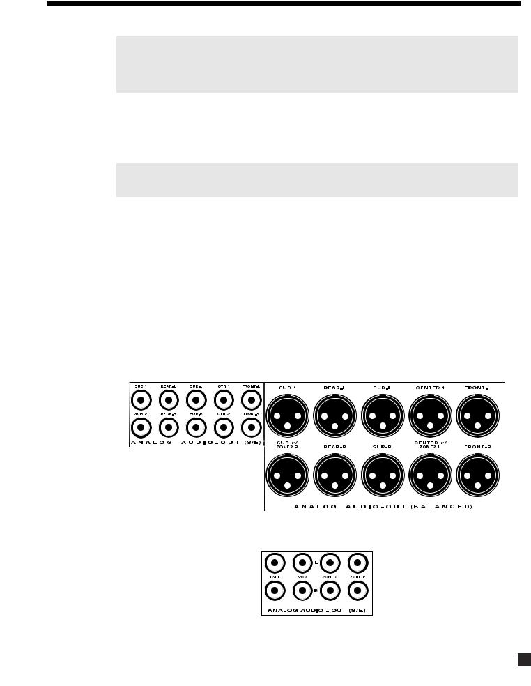
4.2.4 ANALOG AUDIO OUTPUTS
Balanced XLR connection offers the highest transmission quality, particularly over long cable lengths, because it rejects noise and hum pickup. On the AVM 20, XLR output voltage is twice that of RCA output voltage (or 6 dB higher). If your amplifier does not have balanced inputs, use Single-Ended RCA connection.
The AVM 20 also provides parallel outputs for a second Center channel and/or Subwoofer. If the Balanced SUB2 and CENTER2 outputs are not being used for this purpose, they can be re-configured to act as Balanced outputs for ZONE2 to ensure lower noise with longer cable runs (see sections 5.2 and 7.4.7).
If you’re using a 6.1-channel speaker system, with one Rear speaker, Rear-L or Rear-R can be used as the output connection (see section 7.4.2).
The Analog Audio RECORD outputs for your tape recorder and VCR are shown below, together with the outputs for ZONE2 and ZONE3 amplifiers:
16

4. CONNECTIONS continued …
4.3VIDEO CONNECTIONS
The AVM 20 provides video switching for three formats: Composite video, S-Video, and Component video. Format translation is not performed – if only S-Video is used from your VCR, only the S-Video output of the AVM 20 will have a signal to send to your TV monitor whenever the VCR Source is selected. Always remember to select the matching video input on your TV monitor/projector.
The choice of video format depends on the type that is available on your TV monitor/projector. If it only accepts Composite video, then there is no advantage in connecting S-Video or Component video outputs from your DVD player, VCR, or satellite receiver to the AVM 20, and Composite video connection must be used throughout the system (the same applies if you use S-Video or Component video).
The On-Screen Display is available in MAIN and ZONE2 when Composite or S-Video connections are used.
Composite Video:
This is the oldest video format. It combines the black/white and color information for transmission on a single coaxial cable with RCA connectors. These signals must then be separated again within the TV monitor by a comb filter, resulting in some degradation of video quality.
S-Video:
S-Video gives better video quality by transmitting color and brightness separately, using a multi-conductor cable with S-Video connectors (5-pin Mini DIN).
Component Video:
Component video is transmitted over three coaxial cables, is capable of progressive scan mode, and produces the highest video quality. The AVM 20 has four assignable Component video inputs. Note that all 3-wire connections must be made (Y, PR/Cr, PB/Cb). Component-In and Component-Out are compatible with HDTV (up to 1080p) and all other 3-wire component video formats.
Note: Factory default settings are DVD for Component1 and SAT for Component2 (see section 7.4.5).
The AVM 20 does not provide On-Screen Display for the Component video output. If you use Component video, make sure either Composite or S-Video output is also connected from the AVM 20 to your TV. You can then change to that TV input to view the Setup Menu and make changes more conveniently (see section 7).
17

4. CONNECTIONS continued …
DVD Player, Satellite Receiver, and TV Connections with AVM 20 as Video Input Selector
Rear Panel of TV
Audio
Out
L |
Composite |
|
Video In |
||
|
||
Vari |
Fixed |
|
R |
S-Video In |
SATELLITE
Y
|
CATV |
|
|
In |
|
Pb |
Component |
|
Video In |
||
|
||
Pr |
|
Note:
For info on Component Video use, see sections 4.3, 7.4.5, and 7.4.10
DVD |
|
|
|
|
|
|
Component |
Satellite Receiver |
|
|
|
|
|
Video Out |
|
|
|
|
|
Y |
|
|
|
|
|
|
|
|
|
Audio Out |
|
Digital Out |
Composite |
S-Video Out |
Pb |
R |
L |
RCA |
Toslink |
Video Out |
|
|
|
|
|
||||
|
|
|
|
|
|
Pr |
Component
Video Out
DVD Player
|
|
|
|
|
|
|
|
Y |
|
|
|
|
|
|
|
|
|
|
|
|
|
|
|
|
|
|
|
Audio Out |
|
|
Digital Out |
|
Composite |
S-Video Out |
|
|
|
|
RCA |
Toslink |
Video Out |
|
Pb |
|
R |
L |
|
|
|||||
|
|
|
|
|||||
Pr
18

4. CONNECTIONS continued …
4.4POWERED I.R. (INFRA RED) RECEIVERS
External IR repeaters allow the Remote Control to be used from other locations in your home. Once a repeater is wired to a selected room, connect it to one of the three I.R. RECEIVER inputs through the removable terminal block. To use the terminal block, remove it from the AVM 20, loosen the proper screw, insert the wire in the slot, tighten the screw onto the wire, and insert the terminal block into the AVM 20. See section 7.4.9 for Setup information.
In addition, there is no need for an external 12V supply to power the repeaters – use the AVM 20’s built-in supply instead for up to three repeaters, and connect according to the repeater manufacturer’s instructions.
Note: For installers – The AVM 20’s IR inputs sense modulated 38 kHz carrier, not demodulated data. With some control systems, an emitter face-to-face with an IR repeater may be needed.
4.5I.R. (INFRA RED) EMITTERS
External IR emitters, also known as flashers, allow control of your source components from any location in your home that has an IR repeater wired to the back of the AVM 20. Position a flasher in front of the source components and connect to one of the two I.R. EMITTER outputs – IR commands coming in through the rear I.R. RECEIVER inputs are re-transmitted through the flashers.
4.6RELAY TRIGGERS
If your other components have provisions for a trigger, you can automatically turn them on and off together with the AVM 20, or when a specified Source is selected. Connect a trigger output from the AVM 20 to the trigger input of your power amplifier, TV monitor, etc., using a cable with 3.5mm mono mini plugs.
Trigger3 is designed to provide the extra current (up to 200 mA) required by relays in larger projectors and motorized screens. Depending on the equipment, a thicker wire gauge may be required (consult your dealer).
The AVM 20 provides flexible trigger options. From the factory, all the triggers are disabled. Through the Setup Menu, the conditions for enabling triggers can be specified (see section 7.4.9).
4.7FM•AM ANTENNAS
To connect the FM antenna, first connect the two antenna wires to the screw terminals of the 75-ohm to 300-ohm adapter. Then connect the adapter to the FM ANTENNA connector on the AVM 20. If your local cable company provides FM service, connect the cable directly to the AVM 20 instead of using the adapter.
To connect the AM loop antenna, press the spring-loaded tabs of the AM ANTENNA connector, insert the bare ends of the wire from the loop antenna and release the tabs.
Once both antennas are connected, move each of them around until best reception is found. For the FM antenna, this will usually be in a “T” formation.
75-ohm to 300-ohm adapter
19
Loading...