

Page 1

Series
MS278XB
High Performance Signal Analyzer
Operation Manual
Software Version 4.xx
Anritsu Company
490 Jarvis Drive
Morgan Hill, CA 95037-2809
USA
P/N: 10410-00273
Revision: D
Copyright 2007 Anritsu Company
Printed: July 2007
Page 2

Page 3

WARRANTY
The Anritsu product(s) listed on the title page is (are) warranted against defects in materials and workmanship for
three years from the date of shipment.
Anritsu’s obligation covers repairing or replacing products which prove to be defective during the warranty period.
Buyers shall prepay transportation charges for equipment returned to Anritsu for warranty repairs. Obligation is
limited to the original purchaser. Anritsu is not liable for consequential damages.
LIMITATION OF WARRANTY
The foregoing warranty does not apply to Anritsu connectors that have failed due to normal wear. Also, the warranty
does not apply to defects resulting from improper or inadequate maintenance by the Buyer, unauthorized
modification or misuse, or operation outside of the environmental specifications of the product. No other warranty is
expressed or implied, and the remedies provided herein are the Buyer’s sole and exclusive remedies.
DISCLAIMER OF WARRANTY
DISCLAIMER OF WARRANTIES. TO THE MAXIMUM EXTENT PERMITTED BY APPLICABLE LAW, ANRITSU
COMPANY AND ITS SUPPLIERS DISCLAIM ALL WARRANTIES, EITHER EXPRESS OR IMPLIED,
INCLUDING, BUT NOT LIMITED TO, IMPLIED WARRANTIES OF MERCHANTABILITY AND FITNESS FOR A
PARTICULAR PURPOSE, WITH REGARD TO THE SOFTWARE PRODUCT. THE USER ASSUMES THE ENTIRE
RISK OF USING THE PROGRAM. ANY LIABILITY OF PROVIDER OR MANUFACTURER WILL BE LIMITED
EXCLUSIVELY TO PRODUCT REPLACEMENT.
NO LIABILITY FOR CONSEQUENTIAL DAMAGES. TO THE MAXIMUM EXTENT PERMITTED BY
APPLICABLE LAW, IN NO EVENT SHALL ANRITSU COMPANY OR ITS SUPPLIERS BE LIABLE FOR ANY
SPECIAL, INCIDENTAL, INDIRECT, OR CONSEQUENTIAL DAMAGES WHATSOEVER (INCLUDING,
WITHOUT LIMITATION, DAMAGES FOR LOSS OF BUSINESS PROFITS, BUSINESS INTERRUPTION, LOSS
OF BUSINESS INFORMATION, OR ANY OTHER PECUNIARY LOSS) ARISING OUT OF THE USE OF OR
INABILITY TO USE THE SOFTWARE PRODUCTS, EVEN IF ANRITSU COMPANY HAS BEEN ADVISED OF
THE POSSIBILITY OF SUCH DAMAGES. BECAUSE SOME STATES AND JURISDICTIONS DO NOT ALLOW
THE EXCLUSION OR LIMITATION OF LIABILITY FOR CONSEQUENTIAL OR INCIDENTAL DAMAGES, THE
ABOVE LIMITATION MAY NOT APPLY TO YOU.
TRADEMARK ACKNOWLEDGMENTS
Windows, Windows XP, Microsoft Paint, Microsoft Word, Microsoft Access, Microsoft Excel, Microsoft PowerPoint,
and Visual Studio are all registered trademarks of Microsoft Corporation.
Acrobat Reader is a registered trademark of Adobe Corporation.
MATLAB is a registered trademark of The MathWorks Corporation.
NI is a trademark of the National Instruments Corporation.
Signature is a trademark of Anritsu Company.
NOTICE
Anritsu Company has prepared this manual for use by Anritsu Company personnel and customers as a guide for the
proper installation, operation and maintenance of Anritsu Company equipment and computer programs. The
drawings, specifications, and information contained herein are the property of Anritsu Company, and any
unauthorized use or disclosure of these drawings, specifications, and information is prohibited; they shall not be
reproduced, copied, or used in whole or in part as the basis for manufacture or sale of the equipment or software
programs without the prior written consent of Anritsu Company.
UPDATES
Updates, if any, can be downloaded from the Documents area of the Anritsu web site at:
http://www.us.anritsu.com
Page 4

END-USER LICENSE AGREEMENT FOR ANRITSU SOFTWARE
IMPORTANT-READ CAREFULLY: This End-User License Agreement (EULA) is a legal agreement between you
(either an individual or a single entity) and Anritsu for the Signature software product identified above, which
includes computer software and associated media and printed materials, and may include “online” or electronic
documentation (“SOFTWARE PRODUCT” or “SOFTWARE”). By receiving or otherwise using the SOFTWARE
PRODUCT, you agree to be bound by the terms of this EULA.
SOFTWARE PRODUCT LICENSE
The SOFTWARE PRODUCT is protected by copyright laws and international copyright treaties, as well as other
intellectual property laws and treaties. The SOFTWARE PRODUCT is licensed, not sold.
1. GRANT OF LICENSE. This EULA grants you the following rights:
a. You may use ONE copy of the Software Product identified above only on the hardware product (Signature Signal
Analyzer and its internal computer) which it was originally installed. The SOFTWARE is in “use” on a computer
when it is loaded into temporary memory (for example, RAM) or installed into permanent memory (for example, hard
disk, CD-ROM, or other storage device) of that computer. However, installation on a network server for the sole
purpose of internal distribution to one or more other computer(s) shall not constitute “use.”
b. Solely with respect to electronic documents included with the SOFTWARE, you may make an unlimited number of
copies (either in hardcopy or electronic form), provided that such copies shall be used only for internal purposes and
are not republished or distributed to any third party.
2. OWNERSHIP. Except as expressly licensed to you in this Agreement, Anritsu retains all right, title, and interest in
and to the SOFTWARE PRODUCT; provided, however, that, subject to the license grant in Section 1.a and Anritsu's
ownership of the underlying SOFTWARE PRODUCT, you shall own all right, title and interest in and to any
Derivative Technology of the Product created by or for you.
3. COPYRIGHT. All title and copyrights in and to the SOFTWARE PRODUCT (including but not limited to any
images, photographs, animations, video, audio, music, text, and “applets” incorporated into the SOFTWARE
PRODUCT), the accompanying printed materials, and any copies of the SOFTWARE PRODUCT are owned by
Anritsu or its suppliers. The SOFTWARE PRODUCT is protected by copyright laws and international treaty
provisions. Therefore, you must treat the SOFTWARE PRODUCT like any other copyrighted material except that you
may make one copy of the SOFTWARE PRODUCT solely for backup or archival purposes. You may not copy any
printed materials accompanying the SOFTWARE PRODUCT.
4. DESCRIPTION OF OTHER RIGHTS AND LIMITATIONS.
a. Limitations on Reverse Engineering, Decompilation, and Disassembly. You may not reverse engineer, decompile, or
disassemble the SOFTWARE, except and only to the extent that such activity is expressly permitted by applicable law
notwithstanding this limitation.
b. Rental. You may not rent or lease the SOFTWARE PRODUCT.
c. Software Transfer. You may permanently transfer all of your rights under this EULA, provided that you retain no
copies, you transfer all of the SOFTWARE PRODUCT (including the Signature Signal Analyzer, all component parts,
the media and printed materials, any upgrades, this EULA, and, if applicable, the Certificate of Authenticity), and the
recipient agrees to the terms of this EULA.
d. Termination. Without prejudice to any other rights, Anritsu may terminate this EULA if you fail to comply with the
terms and conditions of this EULA. In such event, you must destroy all copies of the SOFTWARE PRODUCT.
5. U.S. GOVERNMENT RESTRICTED RIGHTS. THE SOFTWARE PRODUCT AND DOCUMENTATION ARE
PROVIDED WITH RESTRICTED RIGHTS. USE, DUPLICATION, OR DISCLOSURE BY THE GOVERNMENT IS
SUBJECT TO RESTRICTIONS AS SET FORTH IN SUBPARAGRAPH (C)(1)(II) OF THE RIGHTS IN TECHNICAL
DATA AND COMPUTER SOFTWARE CLAUSE AT DFARS 252.227-7013 OR SUBPARAGRAPHS (C)(1) AND (2) OF
THE COMMERCIAL COMPUTER SOFTWARE-RESTRICTED RIGHTS AT 48 CFR 52.227-19, AS APPLICABLE.
MANUFACTURER IS ANRITSU COMPANY, 490 JARVIS DRIVE, MORGAN HILL, CALIFORNIA 95037-2809.
The Signature software is copyright © 2007, Anritsu Company. All rights are reserved by all parties.
Page 5

Page 6

Page 7

Safety Symbols
To prevent the risk of personal injury or loss related to equipment malfunction, Anritsu Company uses the
following symbols to indicate safety-related information. For your own safety, please read the information
carefully before operating the equipment.
Symbols Used in Manuals
Danger: This indicates a very dangerous procedure that could result in
serious injury or death, or loss related to equipment
malfunction, if not performed properly.
Warning: This indicates a hazardous procedure that could result in
light-to-severe injury or loss related to equipment
malfunction, if proper precautions are not taken.
Caution: This indicates a hazardous procedure th at could re sult in loss
related to equipment malfunction if proper precautions are
not taken.
Safety Symbols Used on Equipment and in Manuals
The following safety symbols are used inside or on the equipment near operation locations to provide
information about safety items and operation precautions. Ensure that you clearly understand the meanings of
the symbols and take the necessary precautions before operating the equipment. Some or all of the following
five symbols may or may not be used on all Anritsu equipment. In addition, there may be other labels attached
to products that are not shown in the diagrams in this manual.
This indicates a prohibited operation. The prohibited operation is indicated symbolically in or near
the barred circle.
This indicates a compulsory safety precaution. The required operation is indicated symbolically in or
near the circle.
This indicates a warning or caution. The contents are indicated symbolically in or near the triangle.
This indicates a note. The contents are described in the box.
These indicate that the marked part should be recycled.
MS278XB OM Safety-1
Page 8

For Safety
Warning: Always refer to the operation manual when working near
locations at which the alert mark, shown on the left, is
attached. If the operation, etc., is performed without heeding
the advice in the operation manual, there is a risk of
personal injury. In addition, the equipment performance may
be reduced.
Moreover, this alert mark is sometimes used with other
marks and descriptions indicating other dangers.
Warning: When supplying power to this equipment, connect the
accessory 3-pin power cord to a 3-pin grounded power
outlet. If a grounded 3-pin outlet is not available, use a
conversion adapter and ground the green wire, or connect
the frame ground on the rear panel of the equipment to
ground. If power is supplied without grounding the
equipment, there is a risk of receiving a severe or fatal
electric shock.
Warning: This equipment can not be repaired by the operator. D
attempt to remove the equipment covers or to disassemble
internal components. Only qualified service technicians with
a knowledge of electrical fire and shock hazards should
service this equipment. There are high-voltage parts in this
equipment presenting a risk of sev ere injury or fatal electric
shock to untrained personnel. In addition, there is a risk of
damage to precision components.
Warning: Use two or more people to lift and move this equipment, or
use an equipment cart. There is a risk of back injury if this
equipment is lifted by one person.
Caution: Electrostatic Discharge (ESD) can damage the highly
sensitive circuits in the instrument. ESD is most likely to
occur as test devices are being connected to, or
disconnected from, the instrument’s front and rear panel
ports and connectors. You can protect the instrument and
test devices by wearing a static-discharge wristband.
Alternatively, you can ground yourself to discharge any static
charge by touching the outer chassis of the grounded
instrument before touching the instrument’s front and rear
panel ports and connectors. Avoid touching the test port
center conductors unless you are properly grounded and
have eliminated the possibility of static discharge.
o not
Repair of damage that is found to be caused by electrostatic
discharge is not covered under warranty.
Safety-2 MS278XB OM
Page 9

Table of Contents
Chapter 1—General Information
1-1 About this Manual. . . . . . . . . . . . . . . . . . . . . . . . . . . . . . . . . . . . . . . . . . . . . . . . . . . . . . . . . . . 1-1
Introduction . . . . . . . . . . . . . . . . . . . . . . . . . . . . . . . . . . . . . . . . . . . . . . . . . . . . . . . . . . . . . 1-1
Associated Documentation . . . . . . . . . . . . . . . . . . . . . . . . . . . . . . . . . . . . . . . . . . . . . . . . . 1-1
Conventions. . . . . . . . . . . . . . . . . . . . . . . . . . . . . . . . . . . . . . . . . . . . . . . . . . . . . . . . . . . . . 1-1
1-2 Product Description . . . . . . . . . . . . . . . . . . . . . . . . . . . . . . . . . . . . . . . . . . . . . . . . . . . . . . . . . 1-2
RF/Analog Architecture . . . . . . . . . . . . . . . . . . . . . . . . . . . . . . . . . . . . . . . . . . . . . . . . . . . . 1-3
Digital Architecture . . . . . . . . . . . . . . . . . . . . . . . . . . . . . . . . . . . . . . . . . . . . . . . . . . . . . . . 1-3
Software Architecture . . . . . . . . . . . . . . . . . . . . . . . . . . . . . . . . . . . . . . . . . . . . . . . . . . . . . 1-4
External Interfaces. . . . . . . . . . . . . . . . . . . . . . . . . . . . . . . . . . . . . . . . . . . . . . . . . . . . . . . . 1-5
Identification Number. . . . . . . . . . . . . . . . . . . . . . . . . . . . . . . . . . . . . . . . . . . . . . . . . . . . . . 1-5
Options and Accessories. . . . . . . . . . . . . . . . . . . . . . . . . . . . . . . . . . . . . . . . . . . . . . . . . . . 1-5
1-3 Preventive Maintenance. . . . . . . . . . . . . . . . . . . . . . . . . . . . . . . . . . . . . . . . . . . . . . . . . . . . . . 1-6
Cleaning the Touch Screen. . . . . . . . . . . . . . . . . . . . . . . . . . . . . . . . . . . . . . . . . . . . . . . . . 1-6
Operating System Integrity . . . . . . . . . . . . . . . . . . . . . . . . . . . . . . . . . . . . . . . . . . . . . . . . . 1-6
Antivirus Protection. . . . . . . . . . . . . . . . . . . . . . . . . . . . . . . . . . . . . . . . . . . . . . . . . . . . . 1-6
Windows Updates. . . . . . . . . . . . . . . . . . . . . . . . . . . . . . . . . . . . . . . . . . . . . . . . . . . . . . 1-6
Operating System Backup and Recovery . . . . . . . . . . . . . . . . . . . . . . . . . . . . . . . . . . . . . . 1-7
Replacing the Line Fuses . . . . . . . . . . . . . . . . . . . . . . . . . . . . . . . . . . . . . . . . . . . . . . . . . . 1-8
Internal Battery . . . . . . . . . . . . . . . . . . . . . . . . . . . . . . . . . . . . . . . . . . . . . . . . . . . . . . . . . . 1-8
Chapter 2—Preparation for Use
2-1 Introduction. . . . . . . . . . . . . . . . . . . . . . . . . . . . . . . . . . . . . . . . . . . . . . . . . . . . . . . . . . . . . . . . 2-1
2-2 Operating Environment. . . . . . . . . . . . . . . . . . . . . . . . . . . . . . . . . . . . . . . . . . . . . . . . . . . . . . . 2-1
2-3 Power Requirements . . . . . . . . . . . . . . . . . . . . . . . . . . . . . . . . . . . . . . . . . . . . . . . . . . . . . . . . 2-1
2-4 Unpacking the Product . . . . . . . . . . . . . . . . . . . . . . . . . . . . . . . . . . . . . . . . . . . . . . . . . . . . . . . 2-2
Initial Inspection. . . . . . . . . . . . . . . . . . . . . . . . . . . . . . . . . . . . . . . . . . . . . . . . . . . . . . . . . . 2-2
Package Contents. . . . . . . . . . . . . . . . . . . . . . . . . . . . . . . . . . . . . . . . . . . . . . . . . . . . . . . . 2-2
2-5 Assembly (optional) . . . . . . . . . . . . . . . . . . . . . . . . . . . . . . . . . . . . . . . . . . . . . . . . . . . . . . . . . 2-3
Rack Mount Installation . . . . . . . . . . . . . . . . . . . . . . . . . . . . . . . . . . . . . . . . . . . . . . . . . . . . 2-3
2-6 Power On Procedure . . . . . . . . . . . . . . . . . . . . . . . . . . . . . . . . . . . . . . . . . . . . . . . . . . . . . . . . 2-5
Instrument Startup. . . . . . . . . . . . . . . . . . . . . . . . . . . . . . . . . . . . . . . . . . . . . . . . . . . . . . . . 2-5
Warm-up Time. . . . . . . . . . . . . . . . . . . . . . . . . . . . . . . . . . . . . . . . . . . . . . . . . . . . . . . . . . . 2-5
Instrument Shutdown. . . . . . . . . . . . . . . . . . . . . . . . . . . . . . . . . . . . . . . . . . . . . . . . . . . . . . 2-6
MS278XB OM i
Page 10

Table of Contents (Continued)
2-7 Configuration. . . . . . . . . . . . . . . . . . . . . . . . . . . . . . . . . . . . . . . . . . . . . . . . . . . . . . . . . . . . . . . 2-6
BIOS Configuration . . . . . . . . . . . . . . . . . . . . . . . . . . . . . . . . . . . . . . . . . . . . . . . . . . . . . . . 2-6
Windows XP Configuration . . . . . . . . . . . . . . . . . . . . . . . . . . . . . . . . . . . . . . . . . . . . . . . . . 2-7
User Installed Applications and Data . . . . . . . . . . . . . . . . . . . . . . . . . . . . . . . . . . . . . . . 2-7
Desktop Properties. . . . . . . . . . . . . . . . . . . . . . . . . . . . . . . . . . . . . . . . . . . . . . . . . . . . . 2-7
User Accounts . . . . . . . . . . . . . . . . . . . . . . . . . . . . . . . . . . . . . . . . . . . . . . . . . . . . . . . . 2-7
Directory Structure . . . . . . . . . . . . . . . . . . . . . . . . . . . . . . . . . . . . . . . . . . . . . . . . . . . . . 2-7
Security Settings. . . . . . . . . . . . . . . . . . . . . . . . . . . . . . . . . . . . . . . . . . . . . . . . . . . . . . . 2-8
Remote Access. . . . . . . . . . . . . . . . . . . . . . . . . . . . . . . . . . . . . . . . . . . . . . . . . . . . . . . . 2-8
Computer Name . . . . . . . . . . . . . . . . . . . . . . . . . . . . . . . . . . . . . . . . . . . . . . . . . . . . . . . 2-8
Third Party Software. . . . . . . . . . . . . . . . . . . . . . . . . . . . . . . . . . . . . . . . . . . . . . . . . . . . 2-8
Hard Disk Configuration . . . . . . . . . . . . . . . . . . . . . . . . . . . . . . . . . . . . . . . . . . . . . . . . . 2-8
Analyzer Configuration . . . . . . . . . . . . . . . . . . . . . . . . . . . . . . . . . . . . . . . . . . . . . . . . . . . . 2-9
Installing Options . . . . . . . . . . . . . . . . . . . . . . . . . . . . . . . . . . . . . . . . . . . . . . . . . . . . . 2-10
Customizing the Tool Bar . . . . . . . . . . . . . . . . . . . . . . . . . . . . . . . . . . . . . . . . . . . . . . . 2-11
2-8 Remote Interface Setup . . . . . . . . . . . . . . . . . . . . . . . . . . . . . . . . . . . . . . . . . . . . . . . . . . . . . 2-12
GPIB Setup . . . . . . . . . . . . . . . . . . . . . . . . . . . . . . . . . . . . . . . . . . . . . . . . . . . . . . . . . . . . 2-12
GPIB Interface Connection. . . . . . . . . . . . . . . . . . . . . . . . . . . . . . . . . . . . . . . . . . . . . . 2-12
GPIB Configuration. . . . . . . . . . . . . . . . . . . . . . . . . . . . . . . . . . . . . . . . . . . . . . . . . . . . 2-13
LAN Setup . . . . . . . . . . . . . . . . . . . . . . . . . . . . . . . . . . . . . . . . . . . . . . . . . . . . . . . . . . . . . 2-16
Network Connections . . . . . . . . . . . . . . . . . . . . . . . . . . . . . . . . . . . . . . . . . . . . . . . . . . 2-16
Network Interface Setup. . . . . . . . . . . . . . . . . . . . . . . . . . . . . . . . . . . . . . . . . . . . . . . . 2-16
2-9 Connecting External Devices . . . . . . . . . . . . . . . . . . . . . . . . . . . . . . . . . . . . . . . . . . . . . . . . . 2-24
Connecting an External Keyboard or Mouse. . . . . . . . . . . . . . . . . . . . . . . . . . . . . . . . . . . 2-24
Connecting an External Monitor . . . . . . . . . . . . . . . . . . . . . . . . . . . . . . . . . . . . . . . . . . . . 2-24
Connecting an External Printer . . . . . . . . . . . . . . . . . . . . . . . . . . . . . . . . . . . . . . . . . . . . . 2-24
Connecting an External USB Device. . . . . . . . . . . . . . . . . . . . . . . . . . . . . . . . . . . . . . . . . 2-27
2-10 Preparation for Storage/Shipment . . . . . . . . . . . . . . . . . . . . . . . . . . . . . . . . . . . . . . . . . . . . . 2-28
Preparation for Storage . . . . . . . . . . . . . . . . . . . . . . . . . . . . . . . . . . . . . . . . . . . . . . . . . . . 2-28
Preparation for Shipment. . . . . . . . . . . . . . . . . . . . . . . . . . . . . . . . . . . . . . . . . . . . . . . . . . 2-28
Use a Suitable Container . . . . . . . . . . . . . . . . . . . . . . . . . . . . . . . . . . . . . . . . . . . . . . . 2-28
Protect the Instrument . . . . . . . . . . . . . . . . . . . . . . . . . . . . . . . . . . . . . . . . . . . . . . . . . 2-28
Cushion the Instrument. . . . . . . . . . . . . . . . . . . . . . . . . . . . . . . . . . . . . . . . . . . . . . . . . 2-28
Seal the Container . . . . . . . . . . . . . . . . . . . . . . . . . . . . . . . . . . . . . . . . . . . . . . . . . . . . 2-28
Address the Container . . . . . . . . . . . . . . . . . . . . . . . . . . . . . . . . . . . . . . . . . . . . . . . . . 2-28
Chapter 3—Instrument Overview
3-1 Introduction. . . . . . . . . . . . . . . . . . . . . . . . . . . . . . . . . . . . . . . . . . . . . . . . . . . . . . . . . . . . . . . . 3-1
3-2 Front Panel Overview . . . . . . . . . . . . . . . . . . . . . . . . . . . . . . . . . . . . . . . . . . . . . . . . . . . . . . . . 3-1
Data Display . . . . . . . . . . . . . . . . . . . . . . . . . . . . . . . . . . . . . . . . . . . . . . . . . . . . . . . . . . . . 3-6
Front Panel Keys . . . . . . . . . . . . . . . . . . . . . . . . . . . . . . . . . . . . . . . . . . . . . . . . . . . . . . . . . 3-6
Major Function Keys. . . . . . . . . . . . . . . . . . . . . . . . . . . . . . . . . . . . . . . . . . . . . . . . . . . . 3-6
Minor Function Keys. . . . . . . . . . . . . . . . . . . . . . . . . . . . . . . . . . . . . . . . . . . . . . . . . . . . 3-7
Numeric and Cursor Keys. . . . . . . . . . . . . . . . . . . . . . . . . . . . . . . . . . . . . . . . . . . . . . . . 3-8
Connectors . . . . . . . . . . . . . . . . . . . . . . . . . . . . . . . . . . . . . . . . . . . . . . . . . . . . . . . . . . . . . 3-9
DVD-ROM/CD-RW Drive. . . . . . . . . . . . . . . . . . . . . . . . . . . . . . . . . . . . . . . . . . . . . . . . . . 3-10
Manually Ejecting the DVD-ROM/CD-RW Drive Tray . . . . . . . . . . . . . . . . . . . . . . . . . 3-10
ii MS278XB OM
Page 11

Table of Contents (Continued)
3-3 Graphical User Interface Overview. . . . . . . . . . . . . . . . . . . . . . . . . . . . . . . . . . . . . . . . . . . . . 3-12
Drop-down Menu Bar . . . . . . . . . . . . . . . . . . . . . . . . . . . . . . . . . . . . . . . . . . . . . . . . . . . . 3-13
File . . . . . . . . . . . . . . . . . . . . . . . . . . . . . . . . . . . . . . . . . . . . . . . . . . . . . . . . . . . . . . . . 3-13
View . . . . . . . . . . . . . . . . . . . . . . . . . . . . . . . . . . . . . . . . . . . . . . . . . . . . . . . . . . . . . . . 3-13
Front Panel. . . . . . . . . . . . . . . . . . . . . . . . . . . . . . . . . . . . . . . . . . . . . . . . . . . . . . . . . . 3-14
Tools. . . . . . . . . . . . . . . . . . . . . . . . . . . . . . . . . . . . . . . . . . . . . . . . . . . . . . . . . . . . . . . 3-15
Help . . . . . . . . . . . . . . . . . . . . . . . . . . . . . . . . . . . . . . . . . . . . . . . . . . . . . . . . . . . . . . . 3-15
Main Menu Bar . . . . . . . . . . . . . . . . . . . . . . . . . . . . . . . . . . . . . . . . . . . . . . . . . . . . . . . . . 3-17
Sub-menu Trees . . . . . . . . . . . . . . . . . . . . . . . . . . . . . . . . . . . . . . . . . . . . . . . . . . . . . . . . 3-19
Entering Data and Fly-out Menus. . . . . . . . . . . . . . . . . . . . . . . . . . . . . . . . . . . . . . . . . 3-19
Toggle Buttons . . . . . . . . . . . . . . . . . . . . . . . . . . . . . . . . . . . . . . . . . . . . . . . . . . . . . . . 3-23
Drop-down Selection Menus . . . . . . . . . . . . . . . . . . . . . . . . . . . . . . . . . . . . . . . . . . . . 3-24
Parameter Entry and Measurement Setup Dialogs. . . . . . . . . . . . . . . . . . . . . . . . . . . . . . 3-24
Alpha-Numeric Entry . . . . . . . . . . . . . . . . . . . . . . . . . . . . . . . . . . . . . . . . . . . . . . . . . . . . . 3-25
Graticule . . . . . . . . . . . . . . . . . . . . . . . . . . . . . . . . . . . . . . . . . . . . . . . . . . . . . . . . . . . . . . 3-26
Spectral Analysis Graticule Displays . . . . . . . . . . . . . . . . . . . . . . . . . . . . . . . . . . . . . . 3-26
Data Displays . . . . . . . . . . . . . . . . . . . . . . . . . . . . . . . . . . . . . . . . . . . . . . . . . . . . . . . . 3-28
Vector Signal Analysis Graticule Displays . . . . . . . . . . . . . . . . . . . . . . . . . . . . . . . . . . 3-30
Instrument Messages and Status Bar . . . . . . . . . . . . . . . . . . . . . . . . . . . . . . . . . . . . . . . . 3-35
General Status Messages . . . . . . . . . . . . . . . . . . . . . . . . . . . . . . . . . . . . . . . . . . . . . . 3-35
Warning Messages. . . . . . . . . . . . . . . . . . . . . . . . . . . . . . . . . . . . . . . . . . . . . . . . . . . . 3-35
Calibration Messages. . . . . . . . . . . . . . . . . . . . . . . . . . . . . . . . . . . . . . . . . . . . . . . . . . 3-35
External Keyboard Hot-key Functions. . . . . . . . . . . . . . . . . . . . . . . . . . . . . . . . . . . . . . . . 3-36
3-4 Instrument Operation . . . . . . . . . . . . . . . . . . . . . . . . . . . . . . . . . . . . . . . . . . . . . . . . . . . . . . . 3-37
Changing Setups. . . . . . . . . . . . . . . . . . . . . . . . . . . . . . . . . . . . . . . . . . . . . . . . . . . . . . . . 3-37
Calibration State . . . . . . . . . . . . . . . . . . . . . . . . . . . . . . . . . . . . . . . . . . . . . . . . . . . . . . . . 3-37
Instrument Preset . . . . . . . . . . . . . . . . . . . . . . . . . . . . . . . . . . . . . . . . . . . . . . . . . . . . . . . 3-37
3-5 Rear Panel and Connector Diagrams. . . . . . . . . . . . . . . . . . . . . . . . . . . . . . . . . . . . . . . . . . . 3-38
Chapter 4—Front Panel Menus
4-1 Introduction. . . . . . . . . . . . . . . . . . . . . . . . . . . . . . . . . . . . . . . . . . . . . . . . . . . . . . . . . . . . . . . . 4-1
4-2 Quick Reference. . . . . . . . . . . . . . . . . . . . . . . . . . . . . . . . . . . . . . . . . . . . . . . . . . . . . . . . . . . . 4-1
MS278XB OM iii
Page 12

Table of Contents (Continued)
4-3 Menu Archive . . . . . . . . . . . . . . . . . . . . . . . . . . . . . . . . . . . . . . . . . . . . . . . . . . . . . . . . . . . . . . 4-4
Frequency Main Menu. . . . . . . . . . . . . . . . . . . . . . . . . . . . . . . . . . . . . . . . . . . . . . . . . . . . . 4-4
Frequencies Menu . . . . . . . . . . . . . . . . . . . . . . . . . . . . . . . . . . . . . . . . . . . . . . . . . . . . . 4-5
Step Size and Offset Menu. . . . . . . . . . . . . . . . . . . . . . . . . . . . . . . . . . . . . . . . . . . . . . . 4-6
Amplitude Main Menu . . . . . . . . . . . . . . . . . . . . . . . . . . . . . . . . . . . . . . . . . . . . . . . . . . . . . 4-7
Amplitude Menu . . . . . . . . . . . . . . . . . . . . . . . . . . . . . . . . . . . . . . . . . . . . . . . . . . . . . . . 4-8
Y-Axis Options Menu . . . . . . . . . . . . . . . . . . . . . . . . . . . . . . . . . . . . . . . . . . . . . . . . . . . 4-9
Bandwidth Main Menu. . . . . . . . . . . . . . . . . . . . . . . . . . . . . . . . . . . . . . . . . . . . . . . . . . . . 4-10
Bandwidth Menu. . . . . . . . . . . . . . . . . . . . . . . . . . . . . . . . . . . . . . . . . . . . . . . . . . . . . . 4-11
Auto Coupling Menu. . . . . . . . . . . . . . . . . . . . . . . . . . . . . . . . . . . . . . . . . . . . . . . . . . . 4-12
Marker Main Menu. . . . . . . . . . . . . . . . . . . . . . . . . . . . . . . . . . . . . . . . . . . . . . . . . . . . . . . 4-13
Marker Select Menu . . . . . . . . . . . . . . . . . . . . . . . . . . . . . . . . . . . . . . . . . . . . . . . . . . . 4-14
Marker to (–>) Menu. . . . . . . . . . . . . . . . . . . . . . . . . . . . . . . . . . . . . . . . . . . . . . . . . . . 4-17
Marker Config Menu. . . . . . . . . . . . . . . . . . . . . . . . . . . . . . . . . . . . . . . . . . . . . . . . . . . 4-18
Display Lines Menu . . . . . . . . . . . . . . . . . . . . . . . . . . . . . . . . . . . . . . . . . . . . . . . . . . . 4-18
Measurement Main Menu . . . . . . . . . . . . . . . . . . . . . . . . . . . . . . . . . . . . . . . . . . . . . . . . . 4-19
Measurement Menu . . . . . . . . . . . . . . . . . . . . . . . . . . . . . . . . . . . . . . . . . . . . . . . . . . . 4-20
Trace Main Menu. . . . . . . . . . . . . . . . . . . . . . . . . . . . . . . . . . . . . . . . . . . . . . . . . . . . . . . . 4-23
Trace Config Menu. . . . . . . . . . . . . . . . . . . . . . . . . . . . . . . . . . . . . . . . . . . . . . . . . . . . 4-24
Display Main Menu . . . . . . . . . . . . . . . . . . . . . . . . . . . . . . . . . . . . . . . . . . . . . . . . . . . . . . 4-25
Display Options Menu. . . . . . . . . . . . . . . . . . . . . . . . . . . . . . . . . . . . . . . . . . . . . . . . . . 4-26
Touch Screen Menu . . . . . . . . . . . . . . . . . . . . . . . . . . . . . . . . . . . . . . . . . . . . . . . . . . . 4-26
Sweep Main Menu. . . . . . . . . . . . . . . . . . . . . . . . . . . . . . . . . . . . . . . . . . . . . . . . . . . . . . . 4-27
Sweep Menu. . . . . . . . . . . . . . . . . . . . . . . . . . . . . . . . . . . . . . . . . . . . . . . . . . . . . . . . . 4-28
Trigger Main Menu. . . . . . . . . . . . . . . . . . . . . . . . . . . . . . . . . . . . . . . . . . . . . . . . . . . . . . . 4-29
Trigger Menu . . . . . . . . . . . . . . . . . . . . . . . . . . . . . . . . . . . . . . . . . . . . . . . . . . . . . . . . 4-30
System Main Menu . . . . . . . . . . . . . . . . . . . . . . . . . . . . . . . . . . . . . . . . . . . . . . . . . . . . . . 4-31
Rear Panel Control Menu. . . . . . . . . . . . . . . . . . . . . . . . . . . . . . . . . . . . . . . . . . . . . . . 4-32
Calibration Menu. . . . . . . . . . . . . . . . . . . . . . . . . . . . . . . . . . . . . . . . . . . . . . . . . . . . . . 4-32
System Information Menu. . . . . . . . . . . . . . . . . . . . . . . . . . . . . . . . . . . . . . . . . . . . . . . 4-32
Configuration Menu . . . . . . . . . . . . . . . . . . . . . . . . . . . . . . . . . . . . . . . . . . . . . . . . . . . 4-33
Remote Control Menu. . . . . . . . . . . . . . . . . . . . . . . . . . . . . . . . . . . . . . . . . . . . . . . . . . 4-33
Service Menu . . . . . . . . . . . . . . . . . . . . . . . . . . . . . . . . . . . . . . . . . . . . . . . . . . . . . . . . 4-34
File Main Menu . . . . . . . . . . . . . . . . . . . . . . . . . . . . . . . . . . . . . . . . . . . . . . . . . . . . . . . . . 4-35
File Menu . . . . . . . . . . . . . . . . . . . . . . . . . . . . . . . . . . . . . . . . . . . . . . . . . . . . . . . . . . . 4-35
iv MS278XB OM
Page 13

Table of Contents (Continued)
4-4 Parameter Entry and Measurement Setup Dialog Archive. . . . . . . . . . . . . . . . . . . . . . . . . . . 4-36
Occupied Bandwidth Setup Dialog . . . . . . . . . . . . . . . . . . . . . . . . . . . . . . . . . . . . . . . . . . 4-36
Channel Power Setup Dialog . . . . . . . . . . . . . . . . . . . . . . . . . . . . . . . . . . . . . . . . . . . . . . 4-37
Adjacent Channel Power (ACP) Setup Dialog. . . . . . . . . . . . . . . . . . . . . . . . . . . . . . . . . . 4-38
Multicarrier Channel Power Setup Dialog . . . . . . . . . . . . . . . . . . . . . . . . . . . . . . . . . . . . . 4-40
CCDF Setup Dialog. . . . . . . . . . . . . . . . . . . . . . . . . . . . . . . . . . . . . . . . . . . . . . . . . . . . . . 4-43
Spectrum Mask Setup Dialog . . . . . . . . . . . . . . . . . . . . . . . . . . . . . . . . . . . . . . . . . . . . . . 4-44
VSA Modulation Parameters Setup Dialog . . . . . . . . . . . . . . . . . . . . . . . . . . . . . . . . . . . . 4-46
WCDMA Graph Type Dialog . . . . . . . . . . . . . . . . . . . . . . . . . . . . . . . . . . . . . . . . . . . . . . . 4-48
WCDMA Setup Dialog. . . . . . . . . . . . . . . . . . . . . . . . . . . . . . . . . . . . . . . . . . . . . . . . . . . . 4-51
TPC Limit Edge Definition Dialog . . . . . . . . . . . . . . . . . . . . . . . . . . . . . . . . . . . . . . . . . . . 4-54
Channel Table Editor Dialog . . . . . . . . . . . . . . . . . . . . . . . . . . . . . . . . . . . . . . . . . . . . . . . 4-55
Customize Tool Bar Dialog . . . . . . . . . . . . . . . . . . . . . . . . . . . . . . . . . . . . . . . . . . . . . . . . 4-56
Options Dialog. . . . . . . . . . . . . . . . . . . . . . . . . . . . . . . . . . . . . . . . . . . . . . . . . . . . . . . . . . 4-56
MATLAB Setup Dialog. . . . . . . . . . . . . . . . . . . . . . . . . . . . . . . . . . . . . . . . . . . . . . . . . . . . 4-57
Chapter 5—Measurements
5-1 Introduction. . . . . . . . . . . . . . . . . . . . . . . . . . . . . . . . . . . . . . . . . . . . . . . . . . . . . . . . . . . . . . . . 5-1
5-2 Basic Measurement Setups . . . . . . . . . . . . . . . . . . . . . . . . . . . . . . . . . . . . . . . . . . . . . . . . . . . 5-1
Setting the Center Frequency . . . . . . . . . . . . . . . . . . . . . . . . . . . . . . . . . . . . . . . . . . . . . . . 5-2
Setting the Frequency Span . . . . . . . . . . . . . . . . . . . . . . . . . . . . . . . . . . . . . . . . . . . . . . . . 5-3
Setting the Start and Stop Frequencies. . . . . . . . . . . . . . . . . . . . . . . . . . . . . . . . . . . . . . . . 5-4
Setting the Reference Level . . . . . . . . . . . . . . . . . . . . . . . . . . . . . . . . . . . . . . . . . . . . . . . . 5-5
Setting the Input Attenuation . . . . . . . . . . . . . . . . . . . . . . . . . . . . . . . . . . . . . . . . . . . . . . . . 5-6
Setting the Scale/Div . . . . . . . . . . . . . . . . . . . . . . . . . . . . . . . . . . . . . . . . . . . . . . . . . . . . . . 5-7
Setting the Resolution Bandwidth . . . . . . . . . . . . . . . . . . . . . . . . . . . . . . . . . . . . . . . . . . . . 5-8
Setting the Video Bandwidth . . . . . . . . . . . . . . . . . . . . . . . . . . . . . . . . . . . . . . . . . . . . . . . . 5-9
Setting the Sweep Time . . . . . . . . . . . . . . . . . . . . . . . . . . . . . . . . . . . . . . . . . . . . . . . . . . 5-10
Setting the Bandwidth Coupling Modes. . . . . . . . . . . . . . . . . . . . . . . . . . . . . . . . . . . . . . . 5-11
Setting Markers . . . . . . . . . . . . . . . . . . . . . . . . . . . . . . . . . . . . . . . . . . . . . . . . . . . . . . . . . 5-12
Setting Trace Modes . . . . . . . . . . . . . . . . . . . . . . . . . . . . . . . . . . . . . . . . . . . . . . . . . . . . . 5-14
Configuring the Triggering. . . . . . . . . . . . . . . . . . . . . . . . . . . . . . . . . . . . . . . . . . . . . . . . . 5-17
5-3 Measurement Examples. . . . . . . . . . . . . . . . . . . . . . . . . . . . . . . . . . . . . . . . . . . . . . . . . . . . . 5-19
Measuring a CW Carrier . . . . . . . . . . . . . . . . . . . . . . . . . . . . . . . . . . . . . . . . . . . . . . . . . . 5-20
Measuring Harmonics . . . . . . . . . . . . . . . . . . . . . . . . . . . . . . . . . . . . . . . . . . . . . . . . . . . . 5-21
Displaying Wide Band FFT Mode . . . . . . . . . . . . . . . . . . . . . . . . . . . . . . . . . . . . . . . . . . . 5-22
Displaying Narrow Band FFT Mode . . . . . . . . . . . . . . . . . . . . . . . . . . . . . . . . . . . . . . . . . 5-23
Measuring a Pulse in the Time Domain. . . . . . . . . . . . . . . . . . . . . . . . . . . . . . . . . . . . . . . 5-24
Displaying Detectors . . . . . . . . . . . . . . . . . . . . . . . . . . . . . . . . . . . . . . . . . . . . . . . . . . . . . 5-25
Displaying Trace Modes . . . . . . . . . . . . . . . . . . . . . . . . . . . . . . . . . . . . . . . . . . . . . . . . . . 5-26
Measuring Phase Noise . . . . . . . . . . . . . . . . . . . . . . . . . . . . . . . . . . . . . . . . . . . . . . . . . . 5-27
5-4 RF Measurements . . . . . . . . . . . . . . . . . . . . . . . . . . . . . . . . . . . . . . . . . . . . . . . . . . . . . . . . . 5-28
Third Order Intercept Measurement . . . . . . . . . . . . . . . . . . . . . . . . . . . . . . . . . . . . . . . . . 5-29
Occupied Bandwidth Measurement. . . . . . . . . . . . . . . . . . . . . . . . . . . . . . . . . . . . . . . . . . 5-30
Channel Power Measurement. . . . . . . . . . . . . . . . . . . . . . . . . . . . . . . . . . . . . . . . . . . . . . 5-31
Adjacent Channel Power Measurement . . . . . . . . . . . . . . . . . . . . . . . . . . . . . . . . . . . . . . 5-33
Multicarrier Channel Power Measurement . . . . . . . . . . . . . . . . . . . . . . . . . . . . . . . . . . . . 5-34
MS278XB OM v
Page 14

Table of Contents (Continued)
5-5 Modulation Measurements . . . . . . . . . . . . . . . . . . . . . . . . . . . . . . . . . . . . . . . . . . . . . . . . . . . 5-35
QPSK Measurement . . . . . . . . . . . . . . . . . . . . . . . . . . . . . . . . . . . . . . . . . . . . . . . . . . . . . 5-36
QAM Measurement . . . . . . . . . . . . . . . . . . . . . . . . . . . . . . . . . . . . . . . . . . . . . . . . . . . . . . 5-40
WCDMA Measurements . . . . . . . . . . . . . . . . . . . . . . . . . . . . . . . . . . . . . . . . . . . . . . . . . . 5-42
Code Domain Power Measurement . . . . . . . . . . . . . . . . . . . . . . . . . . . . . . . . . . . . . . . 5-43
Code Domain Error Measurement . . . . . . . . . . . . . . . . . . . . . . . . . . . . . . . . . . . . . . . . 5-48
QPSK Measurement. . . . . . . . . . . . . . . . . . . . . . . . . . . . . . . . . . . . . . . . . . . . . . . . . . . 5-50
Composite Measurement . . . . . . . . . . . . . . . . . . . . . . . . . . . . . . . . . . . . . . . . . . . . . . . 5-54
Single Code Measurement . . . . . . . . . . . . . . . . . . . . . . . . . . . . . . . . . . . . . . . . . . . . . . 5-56
Single Code with Compressed Mode Measurement . . . . . . . . . . . . . . . . . . . . . . . . . . 5-61
WCDMA Uplink Code Domain Power. . . . . . . . . . . . . . . . . . . . . . . . . . . . . . . . . . . . . . 5-63
WCDMA Uplink Code Domain Single Channel . . . . . . . . . . . . . . . . . . . . . . . . . . . . . . 5-68
5-6 Operation Verification . . . . . . . . . . . . . . . . . . . . . . . . . . . . . . . . . . . . . . . . . . . . . . . . . . . . . . . 5-71
Required Equipment . . . . . . . . . . . . . . . . . . . . . . . . . . . . . . . . . . . . . . . . . . . . . . . . . . . . . 5-71
Reference Oscillator Aging Rate (Optional). . . . . . . . . . . . . . . . . . . . . . . . . . . . . . . . . . . . 5-73
Test Setup . . . . . . . . . . . . . . . . . . . . . . . . . . . . . . . . . . . . . . . . . . . . . . . . . . . . . . . . . . 5-73
Test Procedure. . . . . . . . . . . . . . . . . . . . . . . . . . . . . . . . . . . . . . . . . . . . . . . . . . . . . . . 5-74
Frequency Readout Accuracy . . . . . . . . . . . . . . . . . . . . . . . . . . . . . . . . . . . . . . . . . . . . . . 5-75
Test Setup . . . . . . . . . . . . . . . . . . . . . . . . . . . . . . . . . . . . . . . . . . . . . . . . . . . . . . . . . . 5-75
Test Procedure. . . . . . . . . . . . . . . . . . . . . . . . . . . . . . . . . . . . . . . . . . . . . . . . . . . . . . . 5-75
Frequency Span Accuracy. . . . . . . . . . . . . . . . . . . . . . . . . . . . . . . . . . . . . . . . . . . . . . . . . 5-77
Test Setup . . . . . . . . . . . . . . . . . . . . . . . . . . . . . . . . . . . . . . . . . . . . . . . . . . . . . . . . . . 5-77
Test Procedure. . . . . . . . . . . . . . . . . . . . . . . . . . . . . . . . . . . . . . . . . . . . . . . . . . . . . . . 5-77
Swept Resolution Bandwidth. . . . . . . . . . . . . . . . . . . . . . . . . . . . . . . . . . . . . . . . . . . . . . . 5-79
Test Setup . . . . . . . . . . . . . . . . . . . . . . . . . . . . . . . . . . . . . . . . . . . . . . . . . . . . . . . . . . 5-79
Test Procedure. . . . . . . . . . . . . . . . . . . . . . . . . . . . . . . . . . . . . . . . . . . . . . . . . . . . . . . 5-79
Single Sideband Phase Noise . . . . . . . . . . . . . . . . . . . . . . . . . . . . . . . . . . . . . . . . . . . . . . 5-81
Test Setup . . . . . . . . . . . . . . . . . . . . . . . . . . . . . . . . . . . . . . . . . . . . . . . . . . . . . . . . . . 5-81
Test Procedure. . . . . . . . . . . . . . . . . . . . . . . . . . . . . . . . . . . . . . . . . . . . . . . . . . . . . . . 5-81
Average Noise Level . . . . . . . . . . . . . . . . . . . . . . . . . . . . . . . . . . . . . . . . . . . . . . . . . . . . . 5-84
Test Setup . . . . . . . . . . . . . . . . . . . . . . . . . . . . . . . . . . . . . . . . . . . . . . . . . . . . . . . . . . 5-84
Test Procedure. . . . . . . . . . . . . . . . . . . . . . . . . . . . . . . . . . . . . . . . . . . . . . . . . . . . . . . 5-84
Frequency Response. . . . . . . . . . . . . . . . . . . . . . . . . . . . . . . . . . . . . . . . . . . . . . . . . . . . . 5-87
Test Setup . . . . . . . . . . . . . . . . . . . . . . . . . . . . . . . . . . . . . . . . . . . . . . . . . . . . . . . . . . 5-87
Test Procedure. . . . . . . . . . . . . . . . . . . . . . . . . . . . . . . . . . . . . . . . . . . . . . . . . . . . . . . 5-87
Reference Level Switching Uncertainty. . . . . . . . . . . . . . . . . . . . . . . . . . . . . . . . . . . . . . . 5-89
Test Setup . . . . . . . . . . . . . . . . . . . . . . . . . . . . . . . . . . . . . . . . . . . . . . . . . . . . . . . . . . 5-89
Test Procedure. . . . . . . . . . . . . . . . . . . . . . . . . . . . . . . . . . . . . . . . . . . . . . . . . . . . . . . 5-89
Resolution Bandwidth (RBW) Switching Uncertainty. . . . . . . . . . . . . . . . . . . . . . . . . . . . . 5-91
Test Setup . . . . . . . . . . . . . . . . . . . . . . . . . . . . . . . . . . . . . . . . . . . . . . . . . . . . . . . . . . 5-91
Test Procedure. . . . . . . . . . . . . . . . . . . . . . . . . . . . . . . . . . . . . . . . . . . . . . . . . . . . . . . 5-91
Residual Spurious Response . . . . . . . . . . . . . . . . . . . . . . . . . . . . . . . . . . . . . . . . . . . . . . 5-93
Test Setup . . . . . . . . . . . . . . . . . . . . . . . . . . . . . . . . . . . . . . . . . . . . . . . . . . . . . . . . . . 5-93
Test Procedure. . . . . . . . . . . . . . . . . . . . . . . . . . . . . . . . . . . . . . . . . . . . . . . . . . . . . . . 5-93
Input-related Spurious Response . . . . . . . . . . . . . . . . . . . . . . . . . . . . . . . . . . . . . . . . . . . 5-95
Test Setup . . . . . . . . . . . . . . . . . . . . . . . . . . . . . . . . . . . . . . . . . . . . . . . . . . . . . . . . . . 5-95
Test Procedure. . . . . . . . . . . . . . . . . . . . . . . . . . . . . . . . . . . . . . . . . . . . . . . . . . . . . . . 5-95
vi MS278XB OM
Page 15

Table of Contents (Continued)
Chapter 6—Software Peripherals
6-1 Introduction. . . . . . . . . . . . . . . . . . . . . . . . . . . . . . . . . . . . . . . . . . . . . . . . . . . . . . . . . . . . . . . . 6-1
6-2 Signature–MathWorks Connectivity (Option 40 only). . . . . . . . . . . . . . . . . . . . . . . . . . . . . . . . 6-1
Signature MathWorks Connectivity Description . . . . . . . . . . . . . . . . . . . . . . . . . . . . . . . . . 6-1
Integrated MathWorks Computational Components . . . . . . . . . . . . . . . . . . . . . . . . . . . . . . 6-1
Integrated MathWorks Computational Components–Flow of Events. . . . . . . . . . . . . . . 6-1
PreConditions. . . . . . . . . . . . . . . . . . . . . . . . . . . . . . . . . . . . . . . . . . . . . . . . . . . . . . . . . 6-2
Connecting to MATLAB. . . . . . . . . . . . . . . . . . . . . . . . . . . . . . . . . . . . . . . . . . . . . . . . . . . . 6-2
MATLAB Control . . . . . . . . . . . . . . . . . . . . . . . . . . . . . . . . . . . . . . . . . . . . . . . . . . . . . . . . . 6-4
Advanced MATLAB Functions. . . . . . . . . . . . . . . . . . . . . . . . . . . . . . . . . . . . . . . . . . . . . . . 6-5
6-3 Microsoft Applications. . . . . . . . . . . . . . . . . . . . . . . . . . . . . . . . . . . . . . . . . . . . . . . . . . . . . . . . 6-6
Copying Graphical Screen Images . . . . . . . . . . . . . . . . . . . . . . . . . . . . . . . . . . . . . . . . . . . 6-6
Copying Screen Shots to Image Editors. . . . . . . . . . . . . . . . . . . . . . . . . . . . . . . . . . . . . 6-6
Copying Screen Shots to Office Tools . . . . . . . . . . . . . . . . . . . . . . . . . . . . . . . . . . . . . . 6-6
Exporting Trace Data. . . . . . . . . . . . . . . . . . . . . . . . . . . . . . . . . . . . . . . . . . . . . . . . . . . . . . 6-7
Importing the Trace Data to Excel . . . . . . . . . . . . . . . . . . . . . . . . . . . . . . . . . . . . . . . . . 6-7
Importing the Trace Data to Access . . . . . . . . . . . . . . . . . . . . . . . . . . . . . . . . . . . . . . . . 6-8
Chapter 7—Remote Operation
7-1 Introduction. . . . . . . . . . . . . . . . . . . . . . . . . . . . . . . . . . . . . . . . . . . . . . . . . . . . . . . . . . . . . . . . 7-1
7-2 Remote Desktop. . . . . . . . . . . . . . . . . . . . . . . . . . . . . . . . . . . . . . . . . . . . . . . . . . . . . . . . . . . . 7-1
Setting Up Your Analyzer . . . . . . . . . . . . . . . . . . . . . . . . . . . . . . . . . . . . . . . . . . . . . . . . . . 7-1
Enabling the Analyzer as the Host . . . . . . . . . . . . . . . . . . . . . . . . . . . . . . . . . . . . . . . . . 7-1
Installing the Client Software . . . . . . . . . . . . . . . . . . . . . . . . . . . . . . . . . . . . . . . . . . . . . 7-2
Starting a Remote Desktop Session. . . . . . . . . . . . . . . . . . . . . . . . . . . . . . . . . . . . . . . . 7-3
Advanced Connection Options. . . . . . . . . . . . . . . . . . . . . . . . . . . . . . . . . . . . . . . . . . . . 7-4
Logging Off and Ending a Remote Desktop Session. . . . . . . . . . . . . . . . . . . . . . . . . . . 7-4
Appendix A—Specifications
Subject Index
MS278XB OM vii
Page 16

Page 17

Chapter 1 — General Information
1-1 About this Manual
This manual provides general information, installation, and operating information for the model MS278XB
High Performance Spectrum/Vector Signal Analyzer (SPA/VSA), Signature™. Manual organization is shown
in the table of contents.
Introduction
This chapter provides general information about the MS278XB. It includes a general description of the
analyzer and information on its identification number, related manuals, options, and performance
specifications. This chapter also provides preventative maintenance and customer service information.
The MS278XB manual set is installed on the analyzer’s hard drive as an Adobe Acrobat™ (*.pdf) file. The file
can be viewed on the analyzer’s front panel display using Acrobat Reader™. The file is “linked” such that you
can choose a topic to view from the displayed “bookmark” list and “jump” to the page on which the topic resides.
The text can also be word-searched.
The MS2781B is also equipped with online Help called Signature Help System. The Help system is integrated
into the product software making it context sensitive to front panel actions as well as providing full context
search, advanced navigation controls, and custom bookmarking capabilities. The Signature Help System can
also run independent of the product and is included on the Signature Manuals CD-ROM.
Performance specifications can be found in Appendix A, Specifications, located at the back of the Signature
operation manual. Updates can be downloaded from the Documents area of the Anritsu Internet site:
http://www.us.anritsu.com
Associated Documentation
This manual is one of a three part series containing the following:
• MS278XB Operation Manual, Part Number: 10410-00273
• MS278XB Programming Manual, Part Number: 10410-00274
• MS278XB Maintenance Manual, Part Number: 10410-00275
Conventions
Throughout this manual, the terms MS278XB and analyzer will be used interchangeably to refer to the
instrument. The term DUT is used in place of device under test.
Path names may be used to represent the keystrokes and button presses for a desired action or procedure. The
path name generally begins with a front panel key, keyboard key, or main menu icon selection followed by
additional sub-menu selections, each separated by a vertical line ( | ). Front panel key names and menu
selections are presented in the manual as they are on the system, that is in initial caps, all uppercase letters,
or with symbols as appropriate.
Note: In cases where a sub-menu is automatically expanded by accessing the main menu, the path still shows
that sub-menu as part of the selection.
MS278XB OM 1-1
Page 18

Product Description General Information
1-2 Product Description
The Signature Signal Analyzer is a single instrument that integrates state-of-the-art spectrum, vector signal
and digital modulation analysis into one easy to use instrument. It incorporates the following capabilities:
• Highly accurate spectrum measurements covering the range of 100 Hz to 8 GHz in a single band
• Vector measurements of modulated signals up to 30 MHz bandwidth
• Modulation and signal quality measurements of cellular and WLAN signals at the press of a button
• Multiple sweep and detector modes available in a single multi-trace setup
• Easy to use, customizable Microsoft Windows based User Interface
• Custom waveform and signal analysis using on board direct data linking to MATLAB® and Simulink®
tools
• Control of external signal sources and other instruments via SCPI, IEEE488.2, and Web Services
• Remote Control via a Local Area Network or the Internet
• Ability to run user applications and device drivers on its embedded PC
The advanced design of the Anritsu Signature Signal Analyzer features the following innovations:
• RF/analog architecture optimized for maximum dynamic range, high accuracy, and operation to 8 GHz
in a single band
• Exclusive low conversion loss mixer technology
• Exclusive 2 dB per step impedance-matched input attenuator
• Advanced design digital phase-lock loop local oscillator technology for maximum stability and sweep
speed with lowest phase noise and spurious signals
• Upgradeable open architecture for lowest total cost of ownership
• Field replaceable, pre-calibrated functional modules
• Digital FPGA technology for maximum performance and ease of upgrade
• Industry standard, obsolescence-proof Compact PCI digital modules
• Improved reliability through an advanced, low ambient noise thermal management system
1-2 MS278XB OM
Page 19

General Information Product Description
RF/Analog Architecture
The RF/analog architecture of the Signature Signal Analyzer is designed to maximize performance over a wide
frequency and dynamic range. Signature’s basic RF/analog block diagram is shown in Figure 1-1, below:
Figure 1-1. Basic Signature RF/Analog Block Diagram
The input signal, from either the internal 50 MHz calibrator or the test port input, is routed through the input
attenuator and then to the first mixer where it is converted to the first IF frequency of 9.5 GHz. This allows the
entire range of 100 Hz to 8 GHz to be covered in a single band without the need for preselecting. The signal is
then down-converted in the second mixer to 1.1 GHz. The frequencies of both the first and second local
oscillators can be adjusted to avoid any possible spurious response. In the third mixer, the signal is converted
to 75 MHz. While the system’s pass bandwidth up to this point has been maintained at greater than 100 MHz,
the signal path is now routed to either a wideband 75 MHz IF section, used exclusively for vector signal
analysis, or a lower bandwidth 10.7 MHz IF section, used for spectrum analysis and low bandwidth signal
analysis. While there are prefilters in the RF/analog section, the task of shaping the IF bandwidth is left
mainly to the digital section, where advanced DSP technology can be used.
Digital Architecture
The digital architecture of the Signature Signal Analyzer is built around an industry-standard Compact PCI
based embedded PC. The PC section handles all control, data management, display, and user interface aspects
of the instrument’s operation. In addition to the embedded PC, two specialized modules play important roles in
the instrument’s operation:
• The Digital IF Module employs a state-of-the-art FPGA (Field Programmable Gate Array) to perform IF
bandwidth filtering, detection, and data formatting, as well as providing the heartbeat for the real-time
data acquisition circuitry.
• The optional 30 MHz Wideband IF Module employs an advanced design analog-to-digital conversion
circuit working in conjunction with an LSI based digital signal processing section to capture large
contiguous samples of wideband I/Q data for analysis.
These two modules pass data to the embedded PC for further processing, display, storage or transmission to
external devices.
MS278XB OM 1-3
Page 20

Product Description General Information
Software Architecture
The operating software of the Signature Signal Analyzer is based on the Microsoft® .Net platform and takes
full advantage of the Windows® XP Professional operating system. All of the user interface constructs are
based on the Windows model so that a new user who is familiar with Windows applications can learn to
operate the instrument very quickly.
The fact that the Signature’s main software is a Windows application also means that users can write their
own programs in languages such as Visual Basic to run on the embedded PC and customize the operation of
the instrument. Commercially available software, such as Microsoft Office and MATLAB from The
MathWorks, can also interact with the instrument’s programming and measurement data.
In order to maximize the responsiveness of the system, additional control programs run on dedicated
microcomputers in most of the system’s modules. These programs receive their instructions from the embedded
PC through an internal network, but can operate autonomously to provide high speed hardware real-time
control. This approach frees the instrument from the inherent response time limitations of the Windows-based
PC while improving flexibility and measurement speed.
When used as a standalone instrument, the 8 GHz analyzer can perform the following measurements:
• All typical spectrum analysis, including channel power, carrier to noise ratio, conformance to spectral
mask, peak signal frequency, and amplitude
• All typical vector signal measurements, such as constellation and vector plots, carrier leakage, I/Q
imbalance, and quadrature error
• Smart one-button measurements such as ACPR, signal bandwidth, EVM (error vector magnitude), and
BER (bit error rate)
When configured with one external source, the 8 GHz analyzer can perform the following network
measurements:
• Frequency Response
• Return Loss
• Group Delay
• 1 dB Compression
When configured with two external sources, the 8 GHz analyzer can perform the same set of measurements, as
well as perform the following network measurements:
• Conversion Loss
• Group Delay (frequency translating devices)
• Intermodulation Distortion
nd
• 2
Order Intercept
rd
• 3
Order Intercept
1-4 MS278XB OM
Page 21

General Information Product Description
External Interfaces
In addition to the visible front panel interfaces, the MS278XB provides the following device interfaces:
• IEEE488.2 GPIB: Connects the MS278XB to an external controller for remote programming. This
interface is detailed in the MS278XB Programming Manual, Part Number: 10410-00274.
•Printer: Provides a connection for printers with Parallel (Centronics) interfaces.
• XGA Output: Provides an Extended Graphics Array connector for an external monitor.
• PS/2 Keyboard and Mouse: Provides for the use of an external PS/2 keyboard and mouse.
• Ethernet: Provides network interface and control of the MS278XB. This interface is detailed in the
MS278XB Programming Manual, Part Number: 10410-00274.
•USB: Provides Type A USB ports on the front and rear panel to connect most USB compatible devices.
Identification Number
All Anritsu instruments are assigned a unique six-digit ID number, such as “040101.” This number is affixed to
a decal on the rear panel of each unit. In any correspondence with Anritsu customer service, please use this
number.
Options and Accessories
Table 1-1 and Table 1-2 lists Signature’s options and accessories with a brief description of each.
Table 1-1. Signature’s Available Options List
Option Number Option Description
Option 1 Rack Mount Adapter
Option 1A Slide Mount Adapter
Option 3 GPIB Interface
Option 22 30 MHz IF Bandwidth (includes baseband differential I & Q inputs)
Option 30 WCDMA Modulation Analysis
Option 38 QAM/PSK modulation analysis (requires Option 22)
Option 40 MATLAB Connectivity
Option 41 WiMAX Modulation Analysis
Option 52 Phase Noise Measurements
Option 98 Z540/ISO Guide 25 Calibration
Option 99 Premium Calibration
ES50MMD Extends Warranty to 5 Years
Table 1-2. Signature’s Optio nal Accessories
Part Number Optional Accessory Description
10410-00275 Signature MS278XB Maintenance Manual (Hard Copy)
1N50B Limiter/DC Block, N(m) to N(f), 50 W, 1 MHz to 3 GHz
1N50C Limiter, N(m) to N(f), 50 W, 10 MHz to 18 GHz
42N50A-30 30 dB Attenuator, 50W N(m) to N(f)
12N50-75B 75 W Matching Pad, DC to 3 GHz, 50 W, N(m) to 75 W N(f)
11N50B Power Divider, 1 MHz to 3 GHz, 50 W, N(f) Input, N(f) Output
2100-1 GPIB Cable, 1M
2100-2 GPIB Cable, 2M
70-28 Headset
MS278XB OM 1-5
Page 22

Preventive Maintenance General Information
1-3 Preventive Maintenance
Routine maintenance that can be performed by the operator consists of cleaning the data display, protecting
the operating system, and replacing a defective line fuse.
Cleaning the Touch Screen
The touch screen is protected by a plastic display filter. To clean the display filter, dampen a soft cloth with a
mild soap and water solution, or a commercial window cleaner. Do not use abrasive cleaners, tissues, or paper
towels that can scratch the plastic surface. Gently wipe the display filter to clean.
Operating System Integrity
The Microsoft Windows XP operating system is configured for optimum signal analysis performance when it
leaves the factory. To maintain the system’s operating integrity, follow proper Windows shutdown procedures
and do NOT modify the operating system settings or registry, hard drive partitions, or Anritsu user accounts.
Antivirus Protection
Signature is compatible with McAfee® VirusScan® Enterprise version 8.0.0. Signature has also been
tested with most common antivirus software, but stability is not guaranteed with all antivirus software.
Anritsu recommends that antivirus software be installed when the instrument is connected to a
network/Internet. The user assumes the responsibility to provide antivirus software as this is not
supplied with the instrument.
Windows Updates
Anritsu tests Signature with the latest Microsoft security updates as they become available; however,
not all Microsoft updates are compatible with Signature and may affect the performance of the analyzer,
if installed. Before connecting Signature to the Internet, consult Anritsu customer service for procedures
on how to safeguard the instrument from undesired conditions that could result from Windows
vulnerabilities.
1-6 MS278XB OM
Page 23

General Information Preventive Maintenance
Operating System Backup and Recovery
Signature is configured with the Norton® Ghost® backup and recovery system. This system can be accessed
from the desktop Start menu or by double clicking the Ghost icon in the system tray.
You can configure Ghost to make system backups or recover previous backups through its backup and recovery
dialogs below:
Figure 1-2. Norton Ghost Backup and Recovery Dialog
Ghost backups are stored to a recovery partition (D:) on the Signature hard drive.
In the event that the Signature operating system becomes corrupted or inoperable, the instrument is shipped
with a System Restore DVD that allows a complete system restoration. To restore the system to the original
factory configuration, you will need to boot the instrument from the Norton Ghost CD and have the Signature
System Restore DVD.
Caution: Restoring the system software will remove all user data and programs from the instrument hard drive.
The instrument will be configured exactly as it was when it was shipped from the factory, including the
original option configuration. Before starting the system recovery procedure, back up all user data and
ensure that installation files for any additional software or instrument options is available for
reinstallation.
The Norton Ghost CD will load a menu and prompt you with installation instructions. Follow the on-screen
instructions to reinstall the Signature operating system.
Note: The recovery DVD is printed with the serial number of the instrument and the date when it was made.
Ensure that the proper recovery DVD is used when restoring the Signature system.
For more information about using Norton Ghost, refer to its online Help, which is accessed from the upper
right corner of the dialogs, or to the Norton Ghost user guide, which is found on the Norton Ghost CD shipped
with the instrument.
MS278XB OM 1-7
Page 24

Preventive Maintenance General Information
Replacing the Line Fuses
The line fuses used in the MS278XB are 6.3A, type T fuses. The line fuse values are printed on the rear panel
next to the power connector. Always use a new fuse of the type and rating specified by the fuse markings on the
rear panel of the instrument. To replace the line fuses, follow the procedure below.
Danger: Before changi ng the fuse, always remove the power cord from the power outlet. Th ere is the risk of
receiving a fatal electric shock if the fuse is replaced with the power cord connected.
Refer to Figure 1-3, below, during the following steps:
1. Set the MS278XB to standby mode using the power button and disconnect the power cord from the rear
panel power receptacle.
2. Using a small flat-blade screwdriver, carefully pry under the tab next to the rear panel power receptacle
to open the fuse block cover and gain access to the fuse holder.
3. Slide out the fuse holder.
4. Replace the fuse in the fuse holder.
5. Install the fuse holder back into the rear panel fuse block.
6. Close the cover to secure the fuse holder in place. The cover will close with an audible snap.
Figure 1-3. Replacing the Rear Panel Fuse
7. Reconnect the analyzer to the power source and set the MS278XB to Operate using the front panel power
button.
Internal Battery
The MS278XB has a Lithium battery installed on the CPU assembly. Battery replacement should be referred
to an authorized Anritsu service center.
1-8 MS278XB OM
Page 25

Chapter 2 — Preparation for Use
2-1 Introduction
This chapter provides information for the initial inspection, preparation for use, and installation instructions
for the MS278XB signal analyzer. Information is also included for interfacing the MS278XB through:
• IEEE-488.2 General Purpose Interface Bus
• Ethernet Port
• External Devices
Detailed programming information can be found in the MS278XB programming manual (part number: 10410-
00274) that came with the analyzer on CD or in the online Help system.
2-2 Operating Environment
The MS278XB operational environmental specifications are listed below:
Table 2-1. MS278XB Operational Environmental Specifications
Operating Temperature Range: 0 to +50 degrees Celsius (per MIL-PRF-28800F)
Relative Humidity: 5% to 95% (per MIL-PRF-28800F)
Altitude: 4,600 meters, 43.9 cm Hg
Vibration: Sinusoidal 5 Hz to 55 Hz on 3 axes
2-3 Power Requirements
The MS278XB is equipped with automatic line-power sensing and will operate with any of the following line
voltages: 100V, 120V, 220V, 240V (+5%, –10%), 48–63 Hz, 350 VA. The MS278XB is intended for Installation
Category (Over Voltage Category) II.
Warning: When supplying power to this equipment, connect the accessory 3-
pin power cord to a 3-pin grounded power outlet. If a grounded 3-pin
outlet is not available, use a conversion adapter and ground the
green wire, or connect the frame ground on the rear panel of the
equipment to ground. If power is supplied without grounding the
equipment, there is a risk of receiving a severe or fatal electric shock.
MS278XB OM 2-1
Page 26

Unpacking the Product Preparation for Use
2-4 Unpacking the Product
Initial Inspection
Inspect the shipping container for damage. If the container or cushioning material is damaged, retain until the
contents of the shipment have been checked against the packing list and the instrument has been checked for
mechanical and electrical operation.
If the MS278XB is damaged mechanically, notify your local sales representative or Anritsu Customer Service.
If either the shipping container is damaged or the cushioning material shows signs of stress, notify the carrier
as well as Anritsu. Keep the shipping materials for the carrier’s inspection.
Warning: Use two or more people to lift and move this equipment, or use an
equipment cart. There is a risk of back injury if this equipment is lifted
by one person.
After removing the instrument from the shipping container, inspect the contents against the list found in the
following section.
Package Contents
Signature comes with a standard set of accessories. In addition to the basic instrument, Table 2-1 lists the
standard set of items that are commonly shipped with the base model.
Table 2-2. Standard Shipment Contents
Part Number Description
MS278XB High Performance Signature SPA/VSA
800-XXX Power Cord
60004 Restore Software DVD-ROM
2000-1389 USB Optical Mouse
970-635 Blank CD R/W Disk
631-73 Spare Fuse
Standard Document Set (on CD-ROM and installed in the instrument)
10920-00048 Manuals CD-ROM
10410-00273 MS278XB Operation Manual
10410-00274 MS278XB Programming Manual
10450-00002 Signature Online Help System
2-2 MS278XB OM
Page 27

Preparation for Use Assembly (optional)
2-5 Assembly (optional)
Rack Mount Installation
Instruments that are ordered from the factory with Option 1, Rack Mount, should have the rack mount preinstalled. Option 1 may be ordered at a later time. To install the Option 1 rack mount kit, refer to the
procedure below:
1. Disconnect the line cord and any other attachments from the instrument.
2. Carefully place the instrument on a secure and stable work surface.
3. Using a Phillips screwdriver, remove the two front panel handles and the four feet at the rear (see
Figure 2-1). Save the screws for later use.
Note: The green-headed screws have a metric thread and must be reused in the same locations from which they
were removed. Replacing these screws with different thread, such as SAE threaded screws, will damage
the instrument chassis.
Figure 2-1. Instrument Handles and Feet Removal Diagram
MS278XB OM 2-3
Page 28

Assembly (optional) Preparation for Use
4. Install the rack mount slides over the threaded studs on the rack mount bracket and handle fixtures as
shown in Figure 2-2, below, and secure them in place with the two fastening nuts.
(Push the button at 1 to release and extend the slide.)
Figure 2-2. Rack Mount Slide Assembly Diagram
5. Install the two rack mount bracket and slide assemblies onto the instrument sides using the greenheaded screws removed earlier (Figure 2-3).
Figure 2-3. Rack Mount Assembly Installation Diagram
This completes the installation of the slide assembly.
2-4 MS278XB OM
Page 29

Preparation for Use Power On Procedure
2-6 Power On Procedure
No initial setup is required. After unpacking, the MS278XB is ready for use; however, it is strongly
recommended that you connect an external keyboard and mouse to facilitate ease of use of the Windows
operating system, particularly when installing third-party software (refer to Section 2-4).
The MS278XB is equipped with automatic line-power sensing and will operate with any of the following line
voltages: 100V, 120V, 220V, 240V (+5%, –10%), 48–63 Hz, 350 VA. The MS278XB is intended for Installation
Category (Over Voltage Category) II.
Warning: When supplying power to this equipment, connect the accessory 3-
pin power cord to a 3-pin grounded power outlet. If a grounded 3-pin
outlet is not available, use a conversion adapter and ground the
green wire, or connect the frame ground on the rear panel of the
equipment to ground. If power is supplied without grounding the
equipment, there is a risk of receiving a severe or fatal electric shock.
After the above warning has been addressed, plug the instrument into an adequate mains supply and set the
instrument to Operate by pressing the Standby/Operate front panel key.
Instrument Startup
Signature requires at least two minutes to initially power up, load the system software, and perform a series of
internal calibrations. During this time, informational screens will be displayed.
After the instrument has completed its startup, the Signature application will be running. To access the PC
functions and minimize the Signature application, access the View drop-down menu and select Desktop.
During power-up, the system goes into a “startup” state in which a self-test checks all of the sub-systems for
proper operation; the firmware is also downloaded into the various peripheral devices. During this time, an
informational splash screen is shown as illustrated below:
Figure 2-4. Signature Startup Splash Screen
Warm-up Time
Signature requires 30 minutes warm-up time to meet operating specifications.
MS278XB OM 2-5
Page 30

Configuration Preparation for Use
Instrument Shutdown
To shut down the instrument press and hold the front panel Standby/Operate key for longer than one second.
Windows will begin the shutdown process and automatically close open applications. It is not advised to turn
the power off at the rear panel or pull the power cord until Windows has been properly shut down.
Note: After turning off the instrument, you must wait at least 10 to 15 seconds before turning the instrument back
on again. This delay is required to allow the internal power supplies to discharge and to assure a reliable
cold start.
2-7 Configuration
This section describes the various aspects of the instrument configurations both inside and outside of the main
instrument software. The following system configurations are described below:
• BIOS Configuration
• Windows XP Configuration
• Analyzer Configuration
• Main Menu Tool Bar Configuration
BIOS Configuration
This section describes a few requirements of the BIOS setup.
Caution: It is strongly recommended that you do not enter or change the BIOS settings. The BIOS is configured
at the factory for optimum system performance. Incorrect BIOS settings can render the system
unusable.
Before entering the BIOS, you mu st install a PS2 keyboard. USB de vices are not sup ported outside of
the Windows operating environment.
The BIOS setup utility can be accessed by pressing F2 during the initial power up state when the Anritsu blue
screen appears. If the system proceeds to the Windows XP startup screen, the BIOS will not be entered and the
system will require a restart before BIOS entry can be attempted.
Note: After turning off the instrument, you must wait at least 10 to 15 seconds before turning the instrument back
on again. This delay is required to allow the internal power supplies to discharge and to assure a reliable
cold start.
Once the BIOS setup utility is entered, changes can be made in the usual manner. USB BIOS Legacy
Support must remain disabled and the USB Host Controller must remain enabled. Failure to preserve
these setting may result in display malfunction.
Pressing F3 will load the BIOS Setup Defaults. Pressing F4 will save the current settings (including any
changes that were made) to BIOS and exit the BIOS setup utility.
2-6 MS278XB OM
Page 31

Preparation for Use Configuration
Windows XP Configuration
This section describes the various aspects of the instrument outside of the main instrument software
(Signature application). It specifically addresses the various configurations and properties of the “open”
Windows XP environment that are set at the Factory.
Caution: Changing some of the default Windows XP settings may cause a loss of instr ument control or undesired
instrument behavior. Changing the Windows Regional and Language Options settings may cause
unstable front panel operation. These setting s must be maintained as English (United States) as is set
at the factory by default.
Several of the Windows XP settings (primarily Desktop settings, Folder options, and Task Bar settings) can be
saved and recalled using the File and Settings Transfer Wizard in Windows XP (“migwiz.exe” accessed from
the command line).
Note: The Quick Launch properties and Power Savings settings do not get saved using the “migwiz.exe” tool.
User Installed Applications and Data
If Signature requires service or calibration, the system may be returned to factory specifications and
reimaged with a standard software configuration. User installed applications and data may be lost and
unable to be retrieved. It is advised that user data be backed up or copied and retained by the user.
Applications will need to be reinstalled from their original installation disks. A complete system restore
from a previous user backup is not advised after service or calibration as this will result in the new
calibrations being overwritten, thus voiding the calibration accuracy.
Desktop Properties
Background—Wallpaper set to None.
Screen Saver—Set to None.
Fonts—Size set to Large Fonts and the font properties for the Menu category set to Tahoma 14
with a size of 30.
Power Savings—In the “Home/Office Desk Power Scheme” group, the “Turn Off monitor” setting
should be set to “Never.”
User Accounts
There is one User Account set up by default:
SignatureUser—This account is password protected (the password is “2780”). A password is necessary
for the Remote Desktop feature to work. This account is the default account and is set to Auto Logon.
Directory Structure
The following Directory Structure is used for installation of Signature related programs, files, etc.:
• C:\Signature: Root Directory
• C:\Signature\SignatureHelpSystem: Contains Help Files, Application Notes, Manuals,
Examples, Data Sheets, etc.
• C:\Signature\Bin: Contains Instrument Binary Files
• C:\Signature\Dependencies: Contains Calibration Data, Initialization Files, etc.
• C:\Signature\Setup: Contains Instrument Setup Files
• C:\Signature\External Applications: Contains Executable Files for
Option 41 (WiMAX Modulation Analysis) and Option 52 (Phase Noise Measurements)
MS278XB OM 2-7
Page 32

Configuration Preparation for Use
Security Settings
The following security related settings are configured in the instrument:
• Internet Explorer Security Settings set to High
• Firewall set to On
• Encryption on File System set to Off
• Passwords are Enabled on all User Accounts
Remote Access
GPIB
The default GPIB properties that are set in the factory are:
• GPIB Address 1
• Mode Talker/Listener
Note: You can access the National Instruments GPIB Configuration dialog box directly from the System Menu in
the instrument software for any changes to the GPIB settings. See “GPIB Setup” on page 2-13.
TCP/IP
All default TCP/IP settings are used.
Note: You can access the Windows XP TCP/IP dialog box directly from the System menu in the instrument
software for any changes to the TCP/IP settings. See “LAN Setup” on page 2-18.
Remote Desktop
Refer to the Remote Desktop section in Chapter 7.
Computer Name
The computer name is set to SNXXXXXX (where XXXXXX is the Anritsu serial number for the
instrument).
Third Party Software
The following third party software is loaded onto the instrument’s hard drive:
• Adobe Acrobat Reader
• MATLAB (A special demo version is copied onto the hard disk and requires installation.)
Hard Disk Configuration
One Primary Partition—This is the default booting partition.
One Recovery Partition—This contains a backup of the main partition that can be used to restore the
main partition if the main partition becomes corrupted. This is set up to be as small as possible (about
5% extra space is allocated in addition to the space consumed by the Recovery utility).
2-8 MS278XB OM
Page 33

Preparation for Use Configuration
Analyzer Configuration
This section describes how to determine which instrument options are installed or are available for
installation. Start by selecting Options from the Tools drop-down menu shown below:
Figure 2-5. Tools Drop-down Menu
This displays the Options dialog box (below), which lists the installed options and their availability.
Figure 2-6. Options Dialog
If an option is installed, it will be listed as Installed. If the option is not installed, it will be listed as Install
Now. If the option is not available or requires additional support, such as hardware, it will be indicated as
such.
MS278XB OM 2-9
Page 34

Configuration Preparation for Use
Installing Options
To install an Option, you will need to contact Anritsu customer service to obtain an installation key.
Once the key has been obtained, you can install an option by pressing the Install Now button on the
Options menu. Pressing the Install Now button will open the OptionsWiz dialog below:
Figure 2-7. OptionsWiz Dialog
Enter your key in the Options Code parameter field and press Next. If the key you entered is validated,
you will be informed of a successful installation in the dialog below:
Figure 2-8. OptionsWiz Dialog
2-10 MS278XB OM
Page 35

Preparation for Use Configuration
If the key is not validated, or there are additional requirements to install the option, you will be notified
with a description of the additional requirements in a dialog similar to that shown below:
Figure 2-9. OptionsWiz Dialog
For further assistance with installing options, contact your nearest Anritsu customer service center
found in Table 1-4.
Customizing the Tool Bar
Signature’s tool bar can be customized by adding commonly used icons and eliminating those that are
seldom used. To customize the tool bar, select Tools | Add/Remove Tool Bar Items | Customize... from
the drop down menu bar. The Customize Toolbar dialog is displayed in Figure 2-33, below:
Figure 2-10. Customize Toolbar Dialog
To add icons to the tool bar, select an icon from the available tool bar buttons and press Add –>. To
remove icons from the tool bar, select an icon from the current tool bar buttons and press <– Remove.
Additional tool bar configurations include rearranging the icons and resetting the tool bar icon set to
default.
MS278XB OM 2-11
Page 36
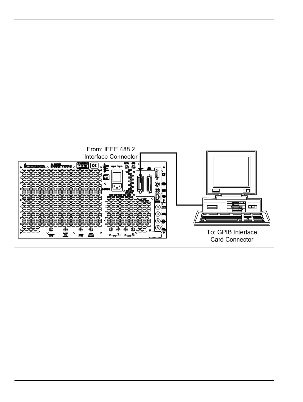
Remote Interface Setup Preparation for Use
2-8 Remote Interface Setup
Most of the MS278XB functions (except power on/off and initialization of the hard disk) can be controlled
remotely by an external computer/controller via the IEEE-488.2 GPIB or a Local Area Network (LAN). The
information in this section pertains to the interface connections and cable requirements for the GPIB Setup
and LAN Setup. Refer to the Model MS278XB Programming Manual, Anritsu Part Number: 10410-00274, for
detailed information about remote programming of the MS278XB using these remote interface options; refer to
Chapter 8, Remote Operation for detailed information on operating the instrument remotely using Windows
Remote Desktop or third party applications, such as WebEX or PCAnywhere™.
GPIB Setup
The MS278XB GPIB operates with any IBM® PC compatible computer/controller equipped with a National
Instruments® GPIB-PCI I/IIA interface card and supporting software.
GPIB Interface Connection
Connect your external controller to the IEEE 488.2 GPIB interface connector on the rear panel as shown
in Figure 2-11.
Figure 2-11. GPIB Interface Connection
The GPIB system can accommodate up to 15 devices at any one time. To achieve maximum performance
on the bus, proper timing and voltage level relationships must be maintained. If either the cable length
between separate instruments or the accumulated cable length between all instruments is too long, the
data and control lines cannot be driven properly and the system may fail to perform. The following
guidelines should be observed:
• No more than 15 instruments may be installed on the bus (including the controller).
• Total accumulative cable length (in meters) may not exceed two times the number of bus
instruments or 20 meters—whichever is less.
• Individual cable length should not exceed 4 meters.
• 2/3 of the devices must be powered on.
• Devices should not be powered on while the bus is in operation (that is; actively sending or
receiving messages, data, etc.).
• Minimize cable lengths to achieve maximum data transfer rates.
2-12 MS278XB OM
Page 37
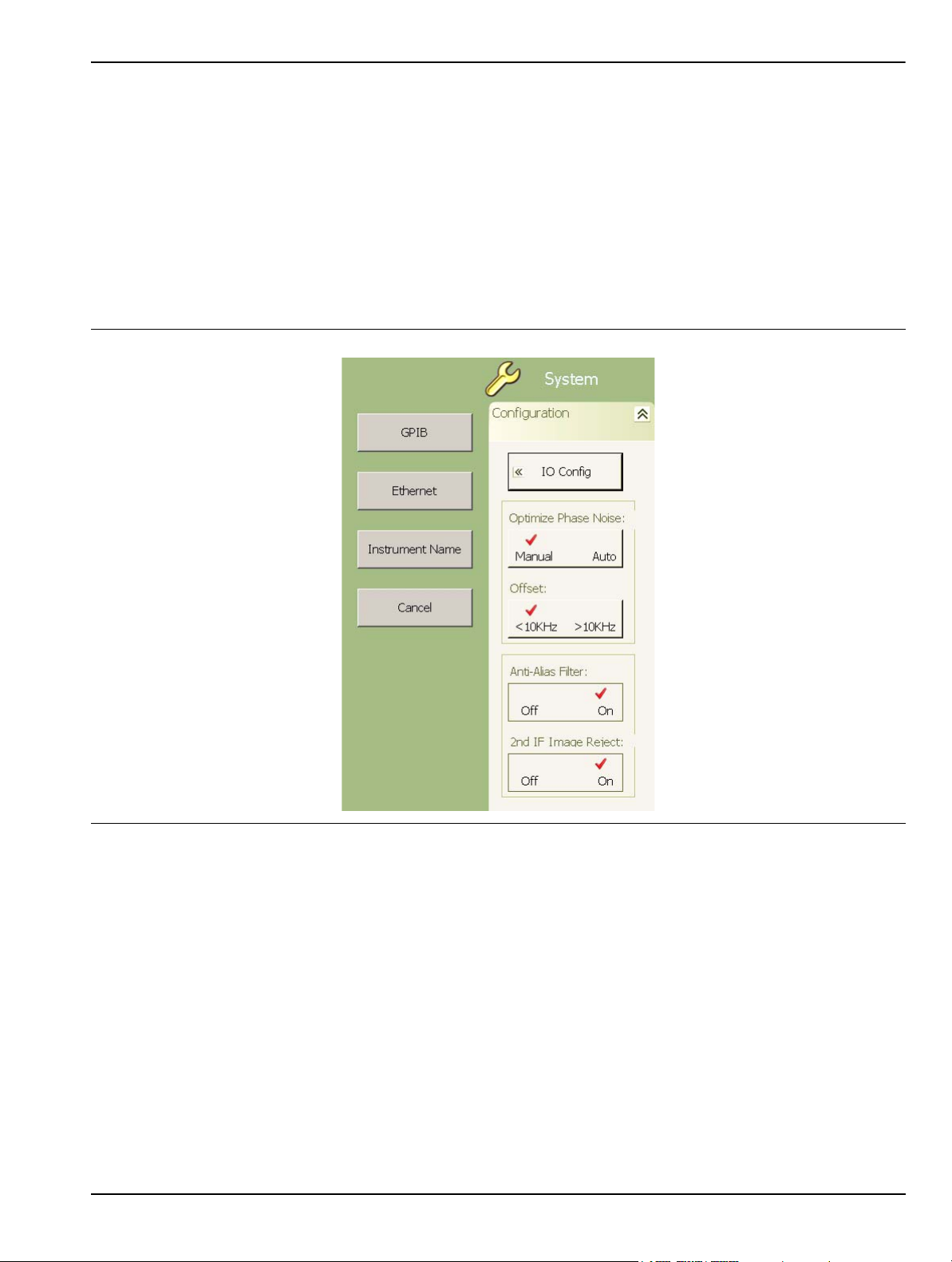
Preparation for Use Remote Interface Setup
GPIB Configuration
Apply power to the MS278XB and allow the system to power up. Once the software has finished loading
and start-up testing is complete, the MS278XB is ready to be remotely controlled via the GPIB. It is
important to note that the MS278XB will not respond to GPIB commands until the system’s software has
been loaded.
The default GPIB address for the MS278XB is one (1). To change the default GPIB address, do the
following on the MS2781B:
1. Access the System main menu by pressing the front panel System button, and then expand the
Configuration sub-menu.
2. Press the IO Config button, and then select GPIB.
Figure 2-12. MS278XB Configuration Sub-menu
MS278XB OM 2-13
Page 38
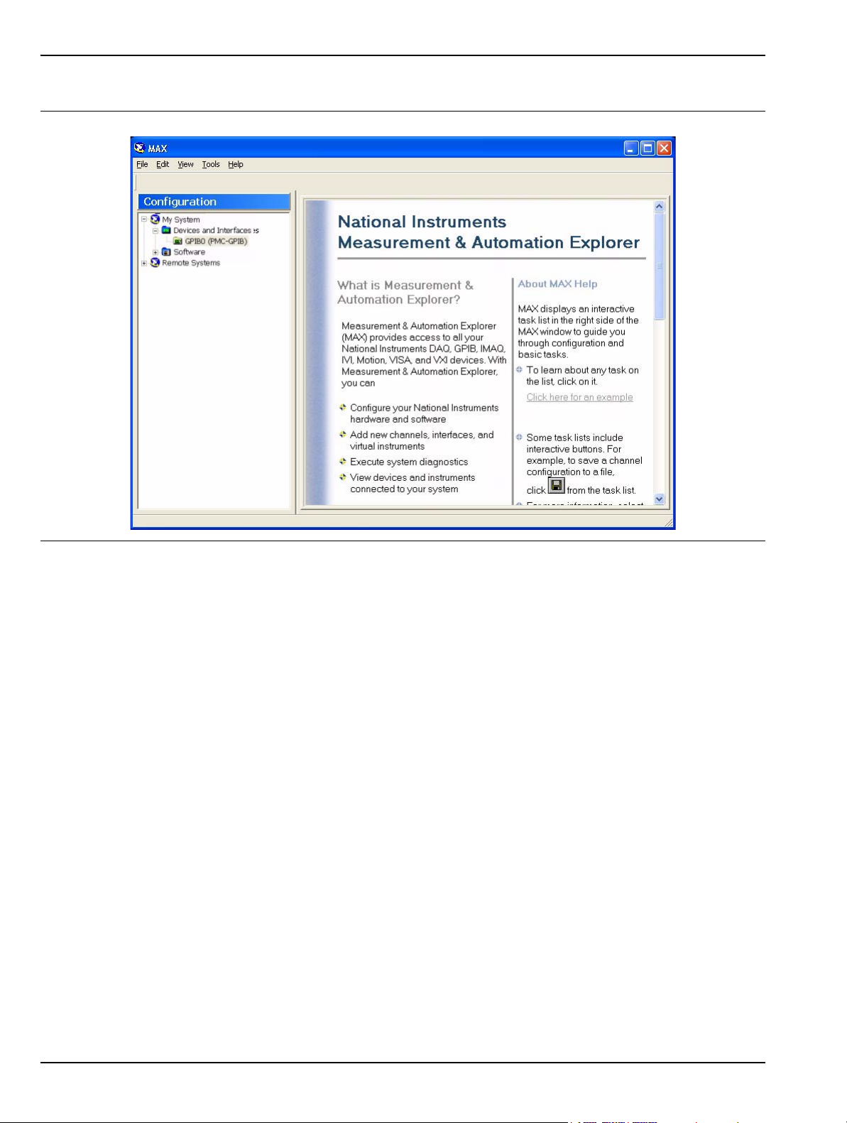
Remote Interface Setup Preparation for Use
This brings up the Measurement and Automation Explorer window, below:
Figure 2-13. National Instruments Measurement and Automation Explorer
3. On the left hand panel, go to My System | Devices and Interfaces | GPIB0 (PMC-GPIB), right click
on GPIB0, and then select properties from the pop-up menu.
2-14 MS278XB OM
Page 39
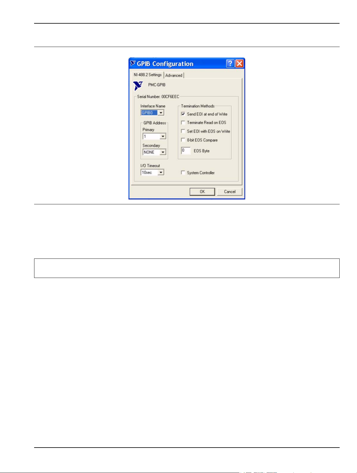
Preparation for Use Remote Interface Setup
4. In the GPIB Configuration dialog, change the Primary GPIB Address to the desired value.
Figure 2-14. National Instruments GPIB Configuration Dialog
Make similar changes on the Remote PC side by selecting the System Controller choice and changing the GPIB
address as required.
When Signature is selected as the system controller, the message “System Controller” is displayed in
Signature’s status bar.
Note: Signature cannot be remotely controlled through GPIB by another remote PC when it is selected as the
system controller.
MS278XB OM 2-15
Page 40
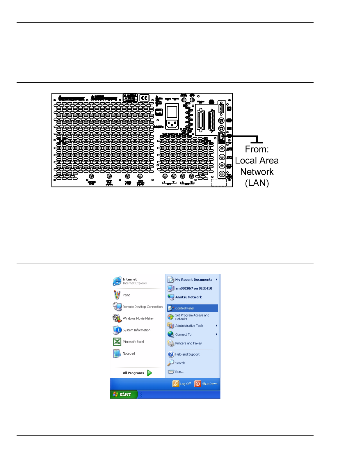
Remote Interface Setup Preparation for Use
LAN Setup
The LAN can be set up via the RJ45 Ethernet port.
Network Connections
The MS278XB supports 10/100 BASE-T. You can connect the analyzer directly to your LAN via the RJ45
connector on the rear panel. Refer to Figure 2-14, below, for an illustration.
Figure 2-15. Ethernet Connection
Network Interface Setup
TCP/IP connectivity requires setting up the parameters described at the beginning of this section. You
may need to contact your network administrator or refer to your network documentation for further
assistance. The following procedure is a general overview of how to set up a general LAN connection on
both the MS278XB and the remote machine. The actual menus and sequence may vary.
1. From the Start menu, select Control Panel.
Figure 2-16. Start Menu
2-16 MS278XB OM
Page 41
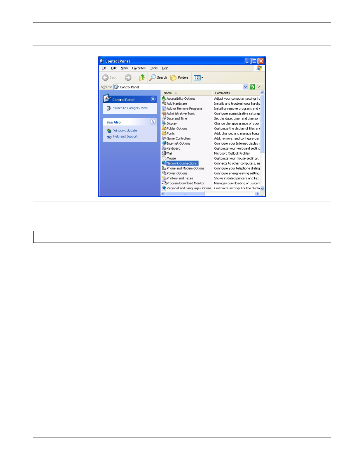
Preparation for Use Remote Interface Setup
2. From the Control Panel, select Network Connections.
Figure 2-17. Control Panel
Note: If your connection already exists and just needs to be modified, skip the next steps a nd proceed to Step 11.
MS278XB OM 2-17
Page 42
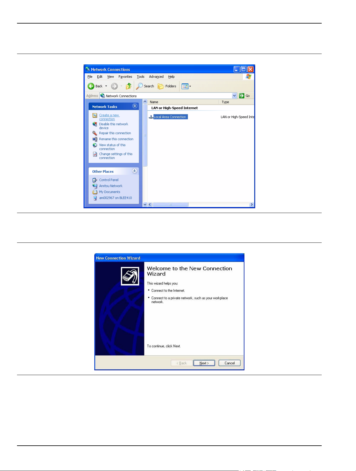
Remote Interface Setup Preparation for Use
3. In the Network Connections window, under Network Tasks on the left pane, select Create a new
connection.
Figure 2-18. Network Connections
4. The New Connection Wizard guides you through the new connection setup. Press Next to continue.
Figure 2-19. New Connection Wizard
2-18 MS278XB OM
Page 43
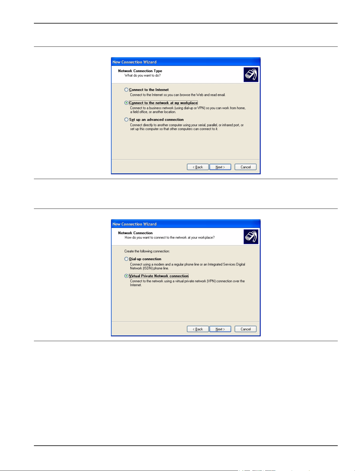
Preparation for Use Remote Interface Setup
5. Select Connect to the network at my workplace and press Next.
Figure 2-20. New Connection Wizard
6. Select Virtual Private Network connection and press Next.
Figure 2-21. New Connection Wizard
MS278XB OM 2-19
Page 44
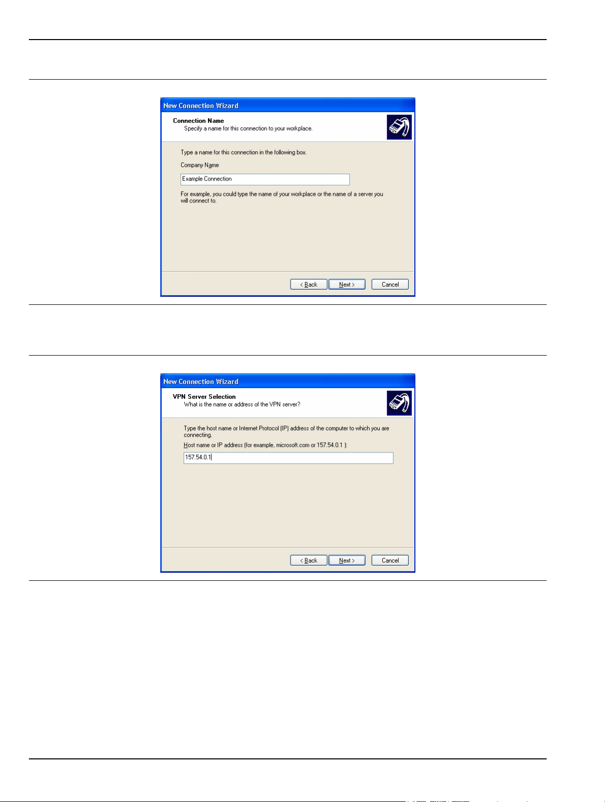
Remote Interface Setup Preparation for Use
7. Enter the name of your new connection and press Next.
Figure 2-22. New Connection Wizard
8. Enter the Host name or IP address for your network.
Figure 2-23. New Connection Wizard
2-20 MS278XB OM
Page 45
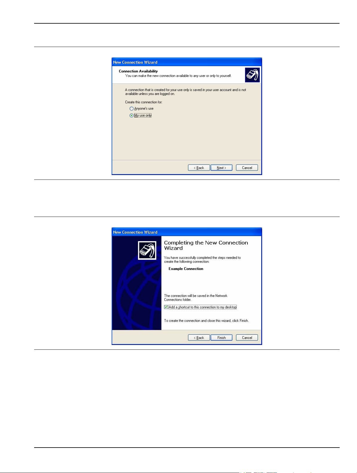
Preparation for Use Remote Interface Setup
9. Select the connection availability of your choice and press Next.
Figure 2-24. New Connection Wizard
10. If you desire to have an Icon placed on the desktop, check the box and press Finish to create your
new connection.
Figure 2-25. New Connection Wizard
MS278XB OM 2-21
Page 46
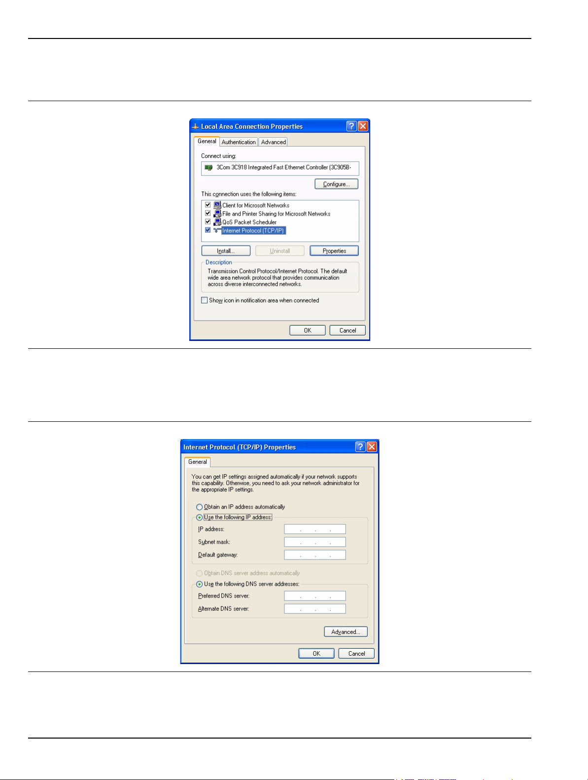
Remote Interface Setup Preparation for Use
11. If a connection needs to be manually set up or modified, you can right click on the connection name
in the Network Connections window (Figure 2-17) and select Properties from the pop-up dialog
box.
Figure 2-26. Local Area Connection Properties
12. From the properties dialog above, select Internet Protocol (TCP/IP) and click on the Properties
button. From here, you can select to dynamically obtain an IP address automatically, or manually
configure your network connection.
Figure 2-27. General Inte rnet Protocol (TCP/IP) Properties
2-22 MS278XB OM
Page 47
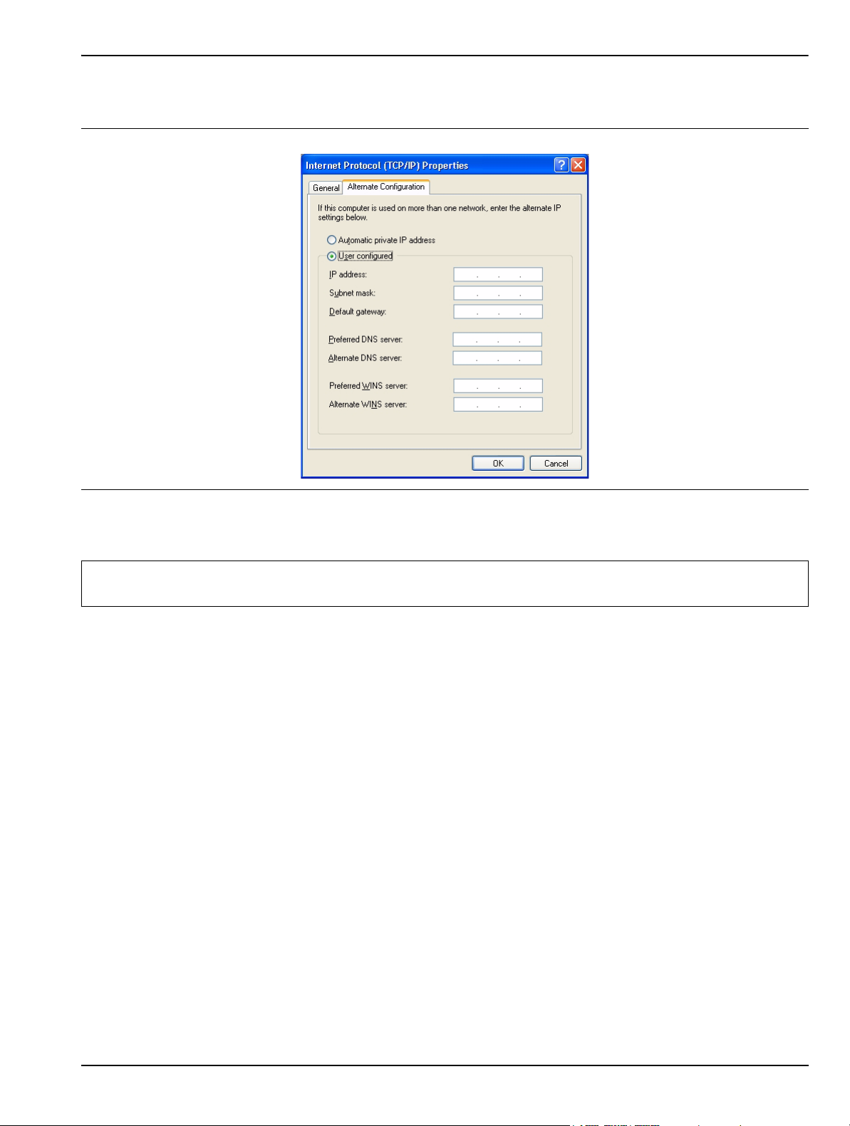
Preparation for Use Remote Interface Setup
13. For additional setup configurations, select Obtain an IP address automatically, then select the
Alternate Configuration tab.
Figure 2-28. Alternate Internet Protocol (TCP/IP) Properties
Note: You may need to consult your network documentation or network administrator for assistance in manually
configuring your network setup.
MS278XB OM 2-23
Page 48
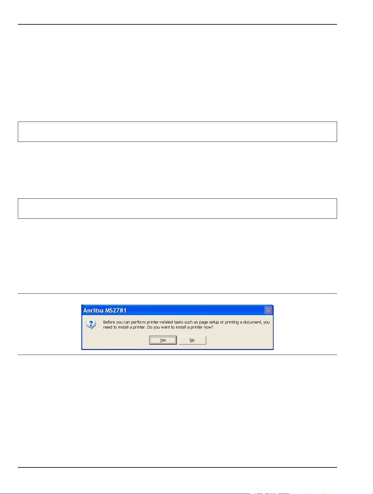
Connecting External Devices Preparation for Use
2-9 Connecting External Devices
Signature offers a variety of external device interfaces that facilitate ease of operation and enhance the
usability of the instrument.
Connecting an External Keyboard or Mouse
The external keyboard and mouse interfaces use standard PS/2 type connectors. When connecting either a PS/
2 keyboard or mouse, ensure that the instrument is set to standby mode before connecting them to the rear
panel. When the MS278XB is set to Operate, the keyboard and mouse should be automatically detected by the
operating system and be ready for use. To use any advanced features of your external keyboard and mouse,
follow the manufacturers installation instructions.
Note: Advanced keyboard and mouse features may not be supported in the analyzer application, but should
function as expected in the Windows environment.
Connecting an External Monitor
The external monitor interface is a standard 15-pin, D-type connector. When connecting an external monitor,
ensure that the instrument is in standby mode and that the monitor is disconnected from its power source.
When the MS278XB is set to Operate, the monitor should be automatically detected by the operating system
and be ready for use.
Note: You may wish to install the monitor’s hardware driver that was provided by the manufacturer to enhance
performance; however, this is not typically necessary.
Connecting an External Printer
The external printer interface is a standard parallel connector. Install your printer driver according to the
manufacturer’s directions. Typically, the hardware connection will need to be made with the analyzer in the
standby, or off, mode to allow for proper initialization of the hardware during boot-up of the operating system.
If you attempt to print while in the Signature application before a printer is installed, you will be prompted to
install a printer. The following procedure is a general overview of how to add a printer. The actual menus and
sequence may vary.
Figure 2-29. Anritsu MS2781 Add Printer Dialog
2-24 MS278XB OM
Page 49
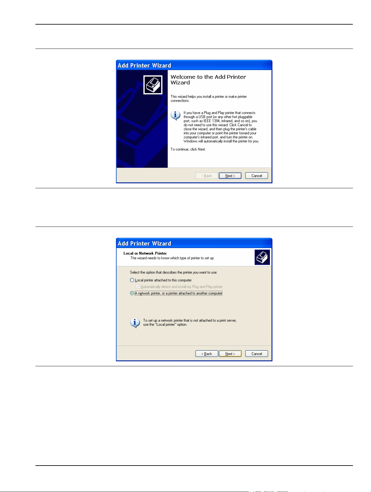
Preparation for Use Connecting External Devices
Pressing Yes will initiate the Windows Add Printer Wizard shown below.
Figure 2-30. Add Printer Wizard
If you are installing a network printer, continue with the Wizard as described below. Otherwise, it is
recommended that you follow the manufacturer’s installation instructions for your printer.
Figure 2-31. Add Printer Wizard
MS278XB OM 2-25
Page 50
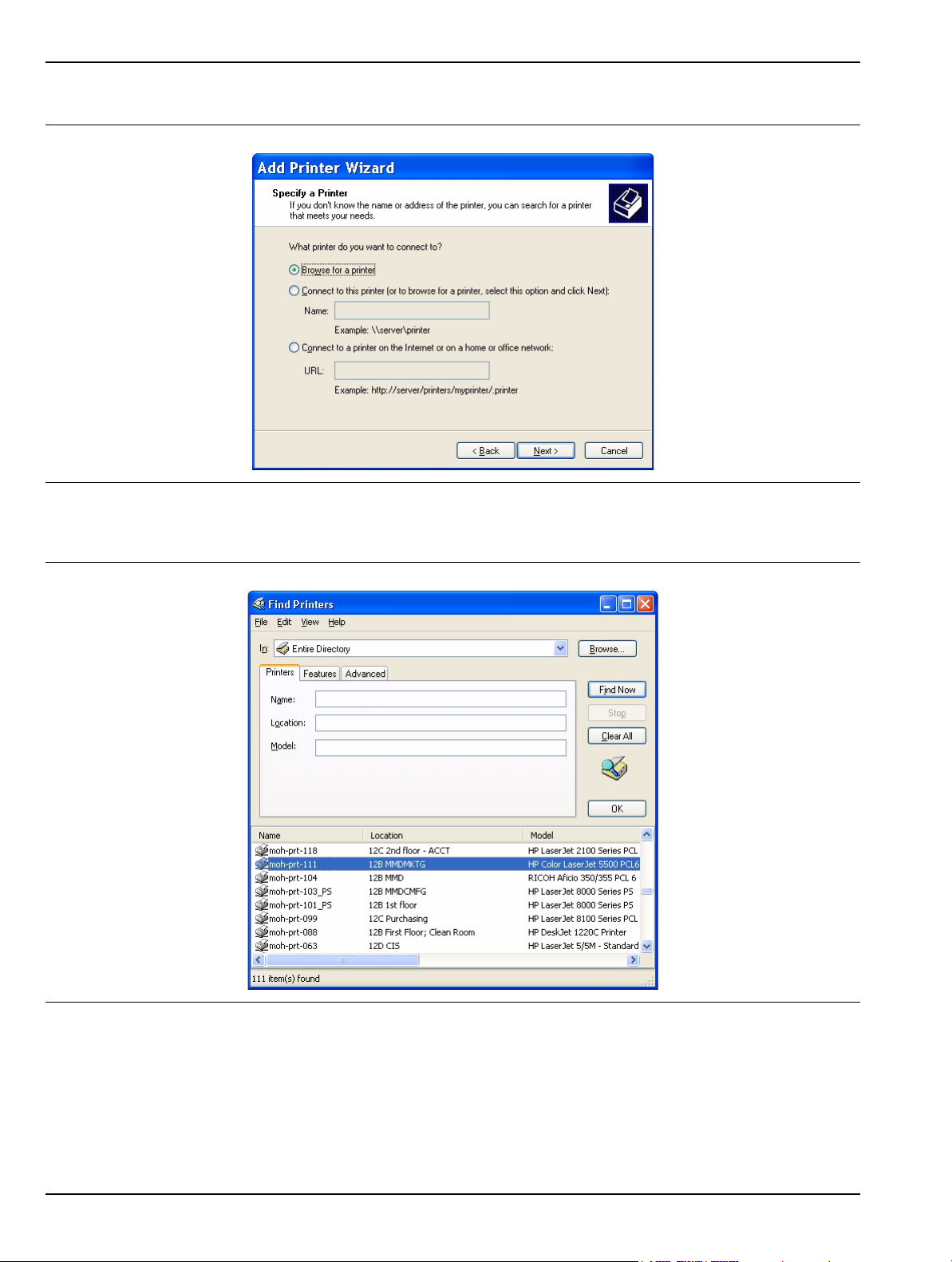
Connecting External Devices Preparation for Use
1. Select the network radio button and press Next.
Figure 2-32. Add Printer Wizard
2. Enter the name and location of your network printer, or select Browse for a printer, then press Next.
Figure 2-33. Find Printers Dialog
2-26 MS278XB OM
Page 51
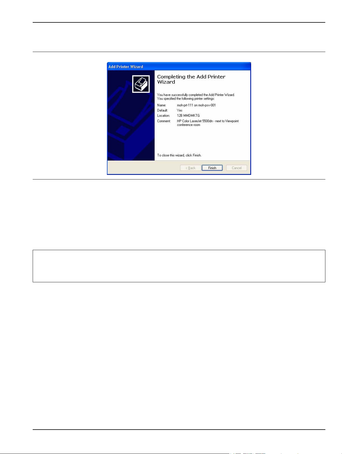
Preparation for Use Connecting External Devices
3. Select the location of your network printer and press Find Now, then select your printer from the list and
press OK.
Figure 2-34. Add Printer Wizard
4. Press Finish to complete the Add Printer Wizard.
Connecting an External USB Device
The external USB interface is a standard Type A, USB connector that supports the USB 2.0 standard.
Signature can interface with a variety of external USB devices, such as a keyboard, mouse, printer, scanner,
drive, or camera. The USB interface offers the same behavior that is typically experienced in the Windows
environment. You may connect your USB devices as directed by the manufacturer’s instructions.
Note: A USB mouse may require a hot connection while the instrument is in the Ope rate mo de with the Signatur e
software running. If a USB mouse fails to operate when the instrument is started with the mouse plugged
into the USB port, reboot the instrument with the mouse disc onnected and make th e hot connection after
the Signature software is running.
MS278XB OM 2-27
Page 52

Preparation for Storage/Shipment Preparation for Use
2-10 Preparation for Storage/Shipment
Preparation for Storage and Shipment
The following paragraphs give instructions for preparing the MS278XB for storage or shipment.
Preparation for Storage
Preparing the analyzer for storage consists of cleaning the unit, packing the inside of the storage container
with moisture-absorbing desiccant crystals, and storing the unit in a temperature controlled environment that
is maintained between –40°C and +75°C.
Preparation for Shipment
To provide maximum protection against damage in transit, the analyzer should be repackaged in the original
shipping container. If this container is no longer available and the unit is being returned to Anritsu for repair,
advise Anritsu Customer Service; they will send a new shipping container free of charge. In the event neither
of these two options is possible, instructions for packaging and shipment are given below.
Use a Suitable Container
Obtain a corrugated cardboard carton with a 125 kg test strength. This carton should have inside
dimensions of no less than 15 cm larger than the unit dimensions to allow for cushioning.
Protect the Instrument
Surround the unit with polyethylene sheeting to protect the finish.
Cushion the Instrument
Cushion the instrument on all sides by tightly packing dunnage or urethane foam between the carton
and the unit. Provide at least three inches of dunnage on all sides.
Seal the Container
Seal the carton by using either shipping tape or an industrial stapler.
Address the Container
If the instrument is being returned to Anritsu for service, mark the address of the appropriate Anritsu
service center and your return address on the carton in one or more prominent locations.
2-28 MS278XB OM
Page 53

Chapter 3 — Instrument Overview
3-1 Introduction
This chapter provides information and instructions on operating the MS2781B signal analyzer using the front
panel controls. It contains the following:
• Illustrations and diagrams of the front panel, data display area, and data entry area that identify and
describe all front panel controls and interfaces.
• An annotated diagram of the menu display showing where the current setup information is located.
• Descriptions of measurement setups through the use of menus, property sheets, and wizards.
• An annotated diagram of the data displays showing where the current setup information and
measurement data is displayed.
• Descriptions of instrument error messages and status indicators.
This chapter also provides detailed information about all of the MS2781B rear panel interfaces and connectors.
3-2 Front Panel Overview
The MS2781B front panel is divided into two main areas—the Graphical User Interface (GUI) and the key pad
data entry area. The following paragraphs provide a brief description of the front panel controls, data display,
and data entry areas shown in Figure 3-1 on the following page. Detailed descriptions of the data display and
data entry areas are contained in Section 3-3.
MS278XB OM 3-1
Page 54
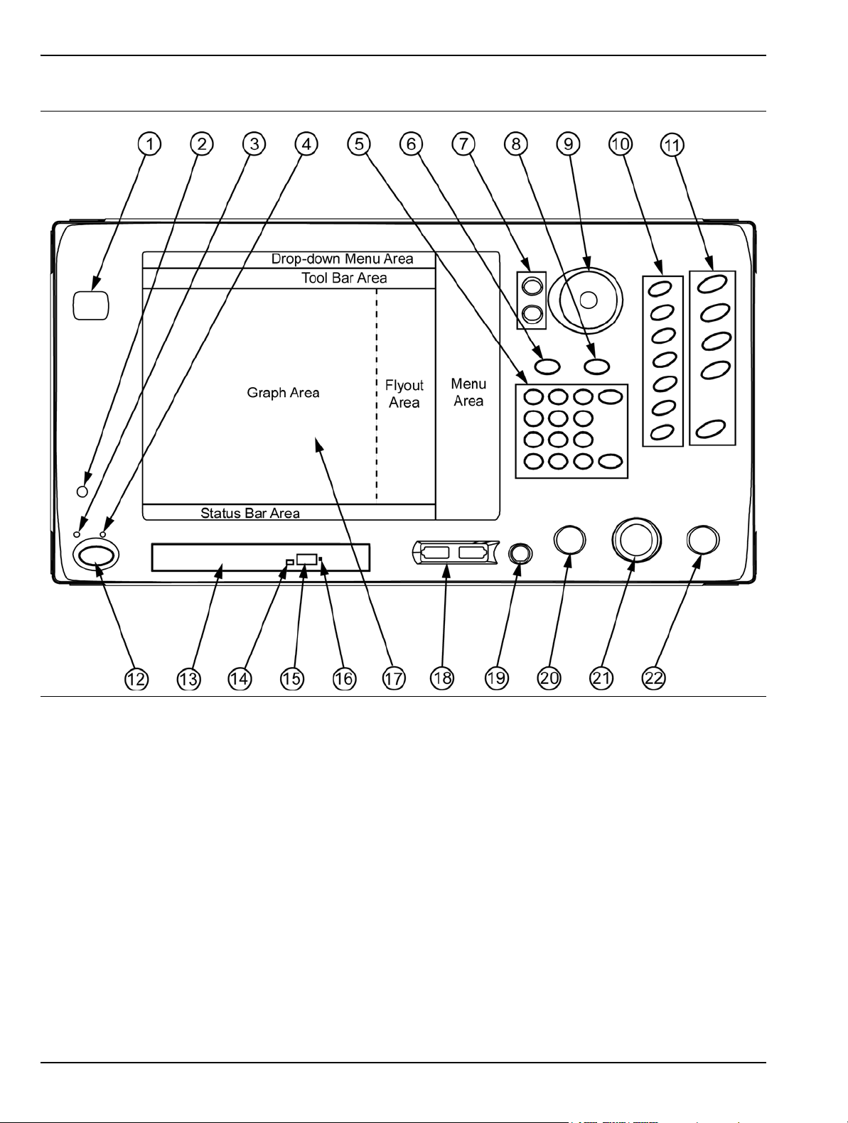
Front Panel Overview Instrument Overview
Figure 3-1. MS278XB Front Panel Drawing
3-2 MS278XB OM
Page 55
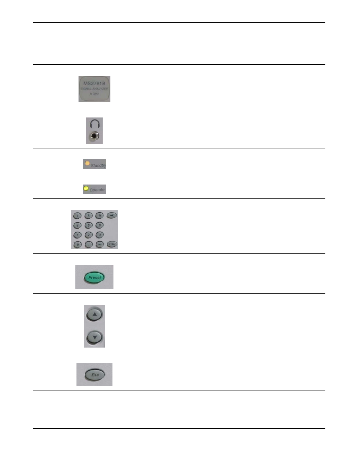
Instrument Overview Front Panel Overview
Table 3-1. MS278XB Front Panel Legend
Index Image Description
1 Instrument Name Tag: The instrument name plate indicates the model
number and upper frequency of the instrument.
2 1/8 Inch Headphone Jack: The h eadphon e jack is used to ou tput audio and
can be used with a standard headphone speaker with a 1/8 inch type mono
or stereo plug.
3 Standby LED: This LED illuminates orange when power is applied and the
instrument is placed in standby mode.
4 Operate LED: This LED illuminates green when power is applied and the
instrument is placed in operate mode.
5 Numeric Keypad: These keys are used for numerical entr y and are listed as
follows: 0,1,2,3,4,5,6,7,8,9, ., +/–, Enter, and Backspace.
6 Preset Function Key: This key sets all of the user settable parameters to
their factory default values.
7 Increment Keys: The increment keys are used to increment a selected
value up or down.
8 Esc Key: The Esc key is used to cancel an initiated function.
MS278XB OM 3-3
Page 56
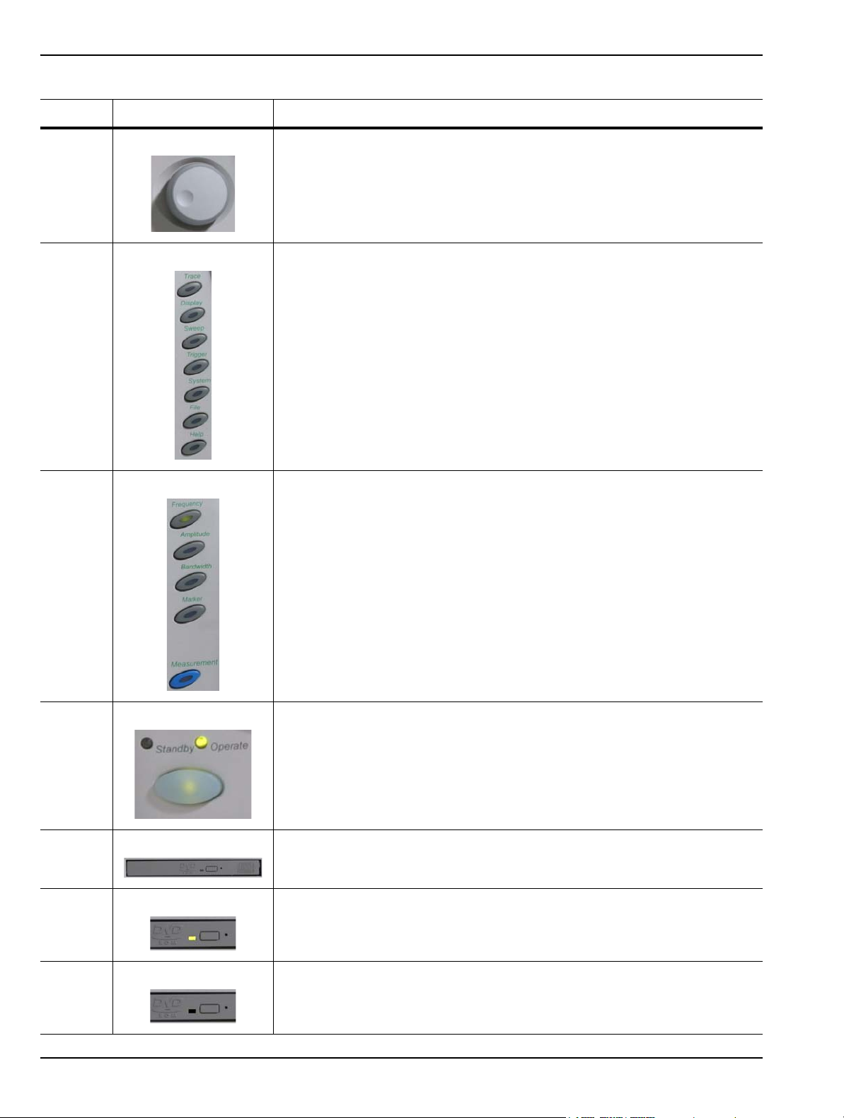
Front Panel Overview Instrument Overview
Table 3-1. MS278XB Front Panel Legend
Index Image Description
9 Rotary Knob: The rotar y knob is used to increment a selected value up or
down.
10 Minor Function Keys: The minor function keys are used to activa te second -
level menus.
11 Major Function Keys: The major function keys are used to activate basic
functional parameter setups and second-level menus found on the GUI.
12 Standby/Operate Key: This key toggles the instrument between standby
and operate mode.
13 DVD-ROM/CD-RW Drive Tray: This tray slid es open and holds your CD
media.
14 DVD-ROM/CD-RW Drive Status LED: This LED illuminates green when
data is being read from the CD media and illuminates yellow when data is
being written to the CD media.
15 DVD-ROM/CD-RW Drive Tray Eject Button: This button is pressed to open
the CD media drive tray.
3-4 MS278XB OM
Page 57
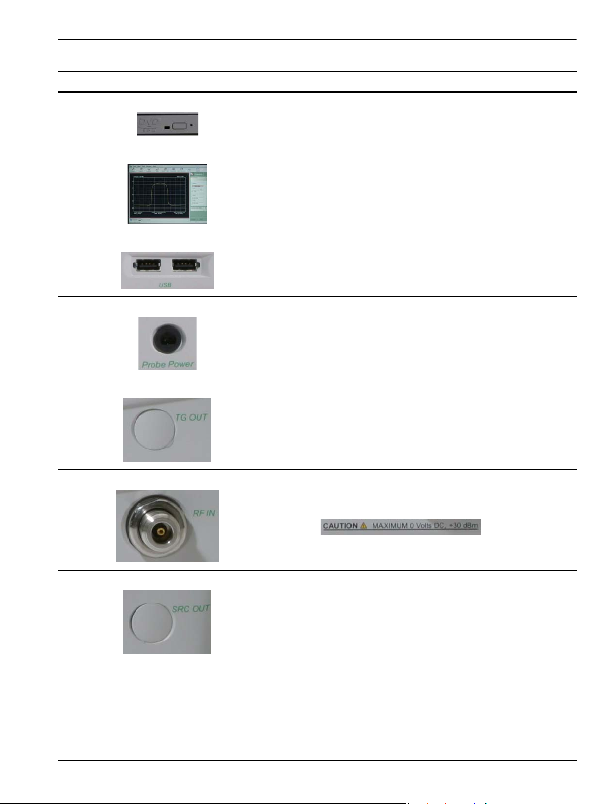
Instrument Overview Front Panel Overview
Table 3-1. MS278XB Front Panel Legend
Index Image Description
16 DVD-ROM/CD-RW Drive Tray Manual Release: The manual release is
used when the drive tray fails to open and needs to be operated manually.
17 Data Display and Touch Panel GUI: The graphical user interface is used to
display measurement data and interactive finger-touch menus.
18 Front Panel USB Ports: The two front panel USB ports offer a convenient
interface access for USB compatible devices.
19 Probe Power Port: This port supplies power to your power probe.
20 Tracking Generator Output Port: This port provides for a Tracking
Generator option. This is a future option and is not used at this time.
21 RF Input Port: The RF Input Port provides the connection to the Device
Under Test. Input specification:
+30 dBm @ 50Ω, MAXIMUM ZERO (0) Volts DC, 100 Hz to 8 GHz
22 Source Output Port: This port provides for an Internal Modulated Source
option. This is a future option and is not used at this time.
MS278XB OM 3-5
Page 58
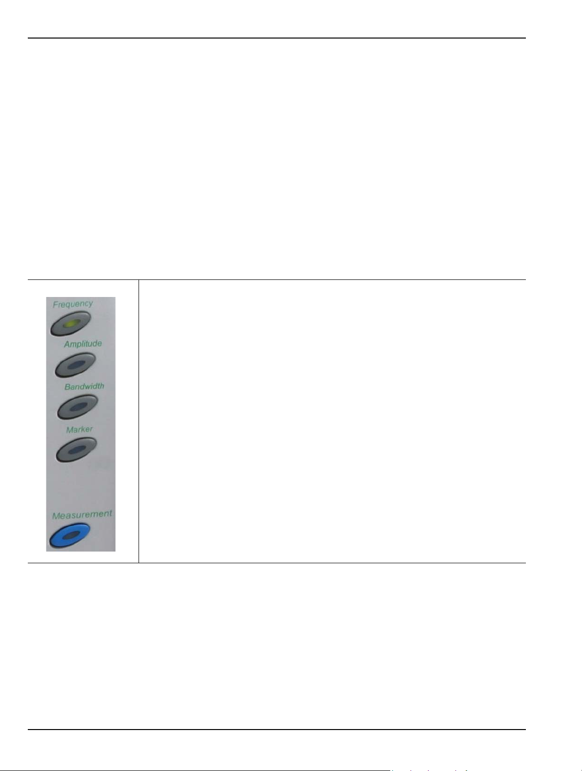
Front Panel Overview Instrument Overview
Data Display
The data display area is the large LCD touch screen. The touch screen is used to display measurements and
function menus. The touch screen has the ability to receive input from the active soft-keys with a simple press
of a finger. The majority of your interface with the analyzer is through the touch screen. Refer to Section 3-3 for
more information about interfacing with the LCD touch screen.
Front Panel Keys
The front panel keypad is used to set the analyzer in and out of standby operation, enter numerical data,
activate functions, and access menus on the GUI. The keypad is divided into groups consisting of the Major
Function Keys, Minor Function Keys, and Numeric Keys.
Major Function Keys
The major function keys are located along the right edge of the front panel and are mapped to key
functions of the instrument that are used most often. These keys activate basic functional parameter
setups and second-level menus found on the GUI. Each of the major function keys have default
parameters associated with them. The default parameter is available for adjustment via the increment
keys or rotary knob after the function is activated. The key becomes illuminated when it’s function is
active. The following list describes each of the key’s functionality:
Frequency: Use this key for accessing the frequency menus. The frequency menus
allow you to set the center, start, and stop frequencies, frequency span, frequency step
size, and frequency offset. The default parameter is the center frequency.
Amplitude: Use this key for accessing the amplitude menus. The am plitude menus allo w
you to set the reference level, attenuation parameters, graticule scaling and units
parameters, and the level offset. The default parameter is the reference level.
Bandwidth: Use this key for accessing the bandwidth menus. The bandwidth menus
allow you to set the resolution and video bandwidths, sweep time, and bandwidth
coupling factors. The default parameter is the resolution bandwidth.
Marker: Use this key for accessing the marker menus. The marker menus allow you to
select the active marker along with the marker mode and access the marker search
functions. The default parameter is the active marker selection.
Measurement: Use this key for accessing the advanced measurement menus. The
advanced measure menus allow you to access the advanced measurement mode s of the
spectrum analyzer, such as RF and Modulation measurements.
Figure 3-2. Major Function Keys
3-6 MS278XB OM
Page 59

Instrument Overview Front Panel Overview
Minor Function Keys
The minor function keys are located just left of the major function keys and activate second-level menu
trees on the GUI. Each of the minor function keys have default parameters associated with them. The
default parameter is available for adjustment via the increment keys or rotary knob after the function is
activated. The key becomes illuminated when it’s function is active. The following list describes each of
the key’s functionality:
Trace: Use this key for accessing the trace menus. The trace menus are used to set the
active trace, select the trace state, set the number of averages for the trace display, and
to select the detector type. The default parameter is the active trace selection.
Display: Use this key for accessing the display menus. The display menus are used to
activate and set display lines. The default parameter is the display line level par ameter.
Sweep: Use this key for accessing the sweep menus. The sweep menus are used to
select between continuous and single sweep, trigger a new sweep, and to select the
sweep mode. The default parameter is the continuous/single sweep selection.
Trigger: Use this key for accessing the trigger menus. The trigger menus are used to
select the trigger source, set the trigger level, select the trigger slope, and to set the
trigger delay. The default parameter is the trigger source selection.
System: Use this key for accessing the system menus. The system menus are used to
access calibration and alignment modes, set up external reference sources, configure
phase noise performance, and to select the remote operating mode. The default
parameter is the calibrator selection mode.
File: Use this key for accessing the file menus. The file menus are used to save and
recall instrument setups and to export trace and measurement data to a file. The default
parameter is the Save selection.
Help: Use this key for accessing the Signature Help system. When this key is pressed,
context sensitive help is enabled and the topics ar e dis pla ye d in th e gr aph ar ea . Pre ss
the key again to toggle the display back to the measurement data.
Figure 3-3. Minor Function Keys
MS278XB OM 3-7
Page 60
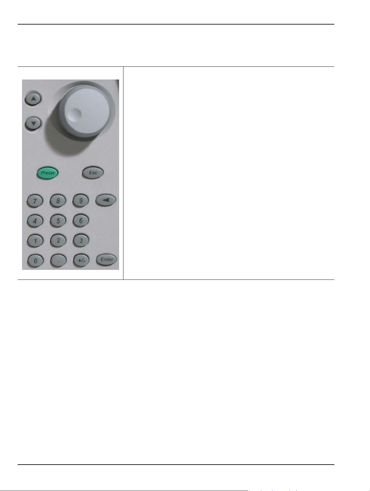
Front Panel Overview Instrument Overview
Numeric and Cursor Keys
The numeric keys are located in a block next to the LCD display. These keys are used for entering and
manipulating data while in a parameter setup function:
Increment Up/Down: Use the increment up/down keys to increment an
active parameter (up or down) and to move an active marker to the next
step. The increment up/down keys allow you to increment or decrement the
active parameter in coarse/discrete steps. These steps usually follow the 1,
2, 3, 5 convention. These keys are mapped to the Page Up/ Page Down
keys on a standard keyboard.
Rotary Knob: The rotary knob functions much like the increment keys and
can be used to adjust active parameters and move active markers. The
rotary knob allows you to increment or decrement the active parameters with
a fine resolution. The rotary knob is m apped to the up/down ar row keys on a
standard keyboard.
Preset: Use this key to access the preset menu. The preset menu allows
you to preset all of the instrument parameters to factory defaults.
Esc: Use this key to escape a function setup or parameter entry that has
been initiated, but is not desired.
Figure 3-4. Numeric Keys
0,1,2...9: Use these keys for entering numerical values.
+/-: Use this key for changing a value’s numerical sign.
.: Use this key for entering a decimal point.
Back Space: Use this key for clearing an active entry.
Enter: Use this key for entering the data or executing a function .
3-8 MS278XB OM
Page 61
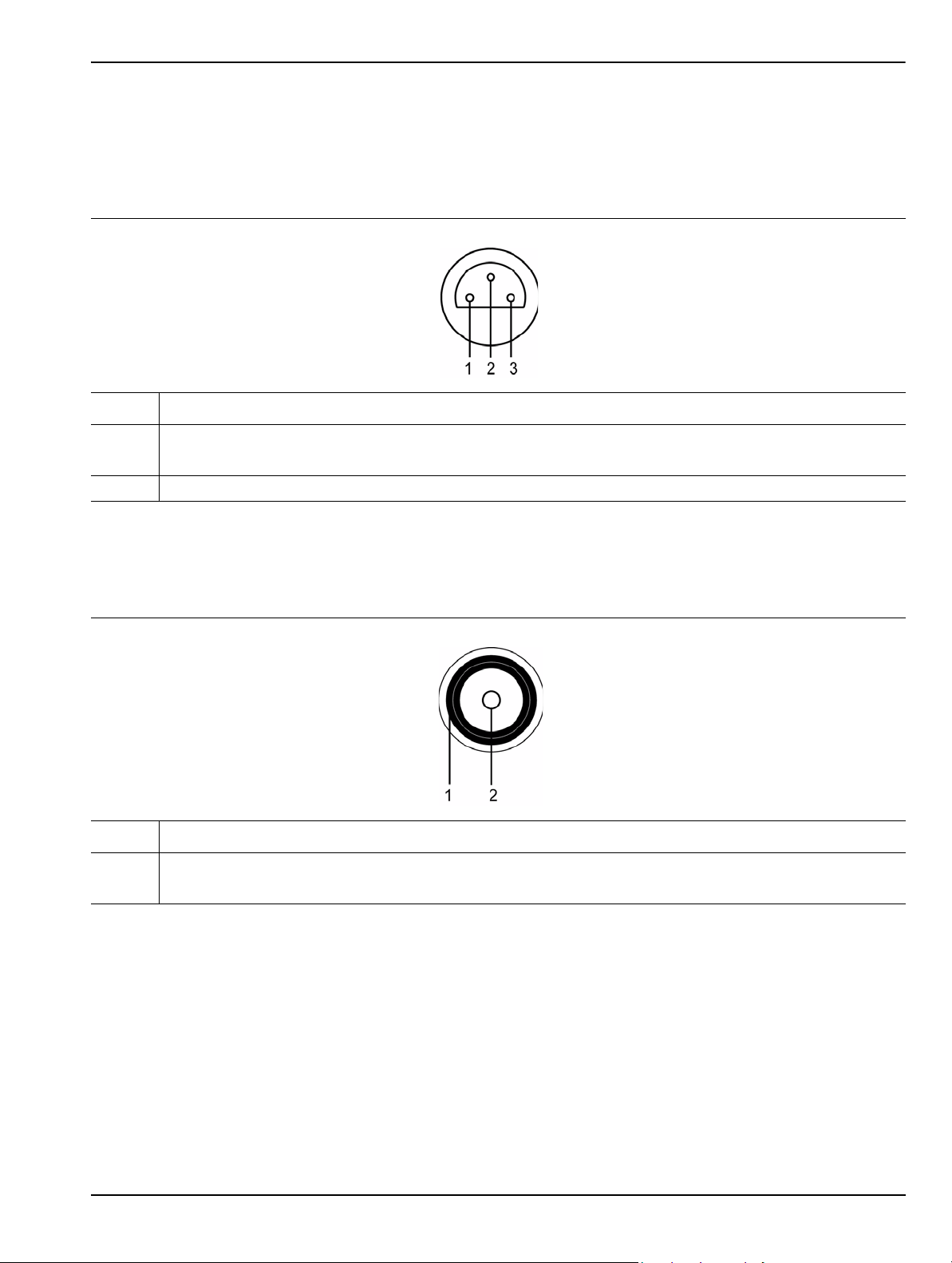
Instrument Overview Front Panel Overview
Connectors
The front panel connectors consist of the following:
• Probe Power Port: This port supplies power to your power probe. Table 3-2 shows the probe power port
pinout.
Table 3-2. Probe Power Port Pinout
Pin Description
1 +15 Vdc at 130 mA
2Ground
3 -12.6 Vdc at 45 mA
• Tracking Generator Output Port: Not used at this time.
• RF Input Port: Ruggedized N-style connector, +30 dBm @ 50Ω, MAXIMUM ZERO (0) Volts DC from
100Hz to 8GHz input.
Table 3-3. RF Input Port
Pin Description
1 Outer Shield and Screw Fastener
2 Center Pin
•Source Output Port: Not used at this time.
MS278XB OM 3-9
Page 62

Front Panel Overview Instrument Overview
DVD-ROM/CD-RW Drive
The DVD-ROM/CD-RW drive is capable of reading digitally stored data on a variety of CD media. The drive is
also capable of writing digital data to CD-R and CD-RW media. You can use either 12 cm or 8 cm diameter
media. The DVD-ROM/CD-RW drive supports ATA Packet Interface (ATAPI), revision 2.6. Performance
specifications for the drive are listed in Table 3-4.
Table 3-4. DVD-ROM/CD-RW Performance Specifications
Function Specification
Compatible Read Disk Types CD-DA, CD+(E)G, CD-MIDI, CD-TEXT, CD-ROM, CD-ROM XA, MIXED MODE,
CD-I, CD-I BRIDGE (PHOTO-CD, VIDEO-CD), CD-R, CD-RW, and
MULTISESSION (PHOTO-CD, CD EXTRA, PORTFOLIO), DVD-ROM (DVD-5,
DVD-9, DVD-10, DVD-18), DVD-R (VER 1.0 and 2.0), DVD-RW (VER 1.1),
DVD-RAM (VER 2.1)
Compatible Write Disk Types CD-R and CD-RW of types listed above
Compatible Write Format Disk at Once
Track at Once
Session at Once
Packet Write
Data Capacity (write) Mode 1: 2048 Bytes/Block
656.5 Megabytes/Disk
Mode 2: 2336 Bytes/Block
748.8 Megabytes/Disk
Access Time DVD-ROM: 100 ms
DVD-RAM: 170 ms
CD-ROM: 90 ms
Maximum Read Speed CD-ROM: 24 Times
DVD-ROM: 8 Times
Maximum Sustained Data
Transfer Rate (read)
Maximum Write Speed CD-R: 24 Times
Maximum Rotational Speed 5100 RPM (CD-ROM, CD-R)
Data Buffer Capacity 2 Megabytes
CD-ROM Mode 1: 3600 Kilobytes/sec.
CD-ROM Mode 2: 4104 Kilobytes/sec.
DVD-ROM Single: 10,820 Kilobytes/sec.
CD-RW: 4 Times
(10 times for high speed CD-RW media)
Caution: Do not use storage media that is of the incorrect type, such as improperly formatted CDs.
Do not insert more than one disk at a time into the drive tray.
Do not use excessive force when loading or ejecting disks.
Failure to follow these cautions could result in loss of data or damage to the equipment.
Manually Ejecting the DVD-ROM/CD-RW Drive Tray
If the CD-RW drive tray fails to eject, a paper clip can be used to release the tray for manual ejection.
Warning: Before proceeding, power down the instrument and remove the power cord from the rear panel power
receptacle.
3-10 MS278XB OM
Page 63

Instrument Overview Front Panel Overview
15 mm
1.0 mm Diameter
1. To release the drive tray, insert a 1.0 mm diameter paper clip into the manual release hole as
shown in Figure 3-5.
Figure 3-5. Manually Ejecting the CD-RW Drive Tray
2. Gently slide the tray open and remove your disk from the drive tray.
3. Remove the paper clip and carefully slide the drive tray completely closed.
If the drive tray does not slide smoothly, or there is excessive resistance, the mechanism may be
damaged and in need of service from an authorized Anritsu service center.
MS278XB OM 3-11
Page 64
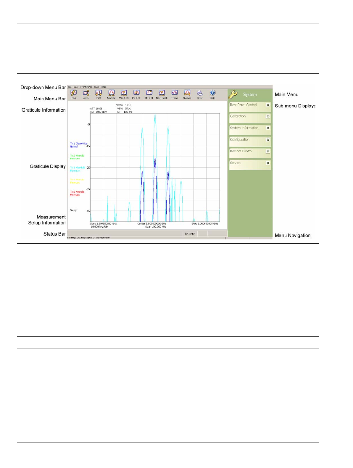
Graphical User Interface Overview Instrument Overview
3-3 Graphical User Interface Overview
This section provides descriptions of the front panel graphical user interface, here forth referred to as the GUI.
The GUI is the LCD touch screen that can be accessed through direct touch or with a pointing device such as a
mouse. Figure 3-6 shows an annotated GUI.
Figure 3-6. MS278XB Graphical User Interface
The major elements displayed on the LCD screen are the:
• MS-Windows style Drop-down Menu Bar
• Main Menu Bar
• Graticule and Measurement Setup Information
• Graticule and Data Display
• Main Menu Bar with Sub-menu Trees
• Instrument Messages and Status Bar
Warning: Do not use sharp objects, such as a pen or pencil, to touch the screen as damage may result.
3-12 MS278XB OM
Page 65
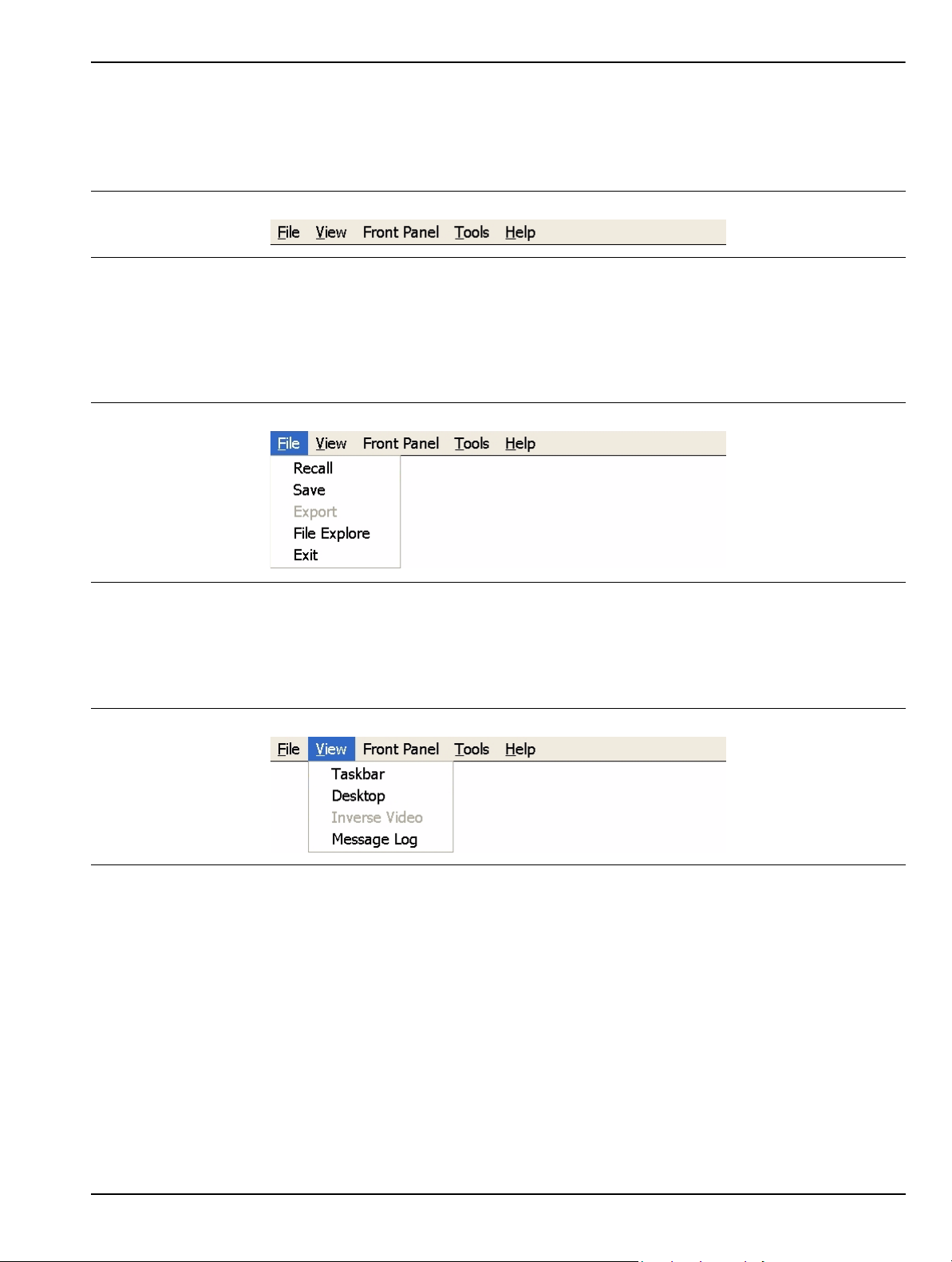
Instrument Overview Graphical User Interface Overview
Drop-down Menu Bar
The drop-down menus along the top of the screen conform to MS-Windows standards. They provide consistent
application interfacing as that found in standard MS-Windows applications. In addition, there are menu
selections that allow you to activate the major/minor functions found on the front panel assembly.
Figure 3-7. Drop-down Menu Bar
File
The File drop-down menu provides access to saving and recalling instrument setups, exporting trace
data, opening Windows File Explorer, or exiting the instrument application. The File drop-down menu
can be quickly accessed using the Alt-F keyboard combination.
Figure 3-8. File Drop-down Menus
View
The View drop-down menu provides access to display control and facilitates access to the Windows
Taskbar. The View drop-down menu can be quickly accessed using the Alt-V keyboard combination.
Figure 3-9. View Drop-down Menus
Taskbar
When you select Taskbar, the Windows Taskbar will be displayed allowing you to access the Windows
operating system and other third party software applications.
Desktop
This menu selection minimizes all open windows and shows the desktop.
Inverse Video
The Inverse Video selection inverts the video colors of the graph area. This is useful to enhance the
contrast between certain colors and for extracting graphical data to display in print format.
Message Log
Selecting Message Log opens the instrument message log on page 3-35.
MS278XB OM 3-13
Page 66
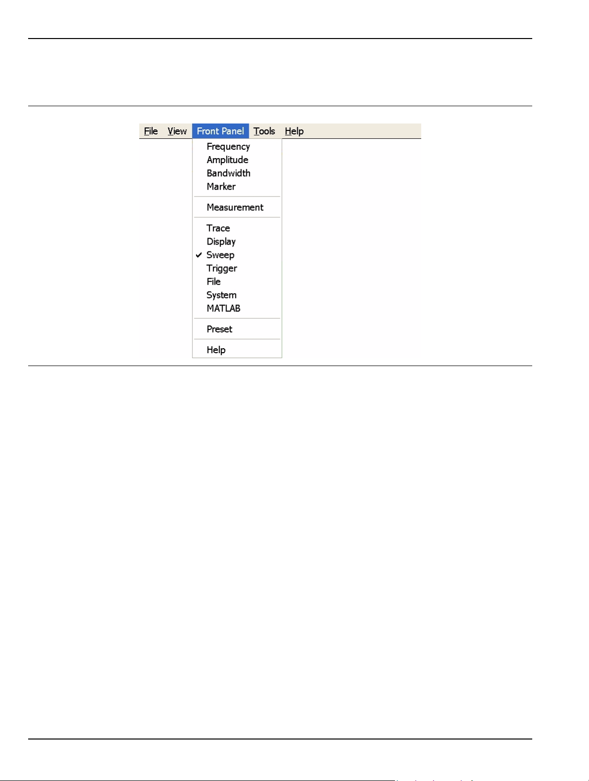
Graphical User Interface Overview Instrument Overview
Front Panel
The Front Panel drop-down menu provides access to all of the instrument’s main menus and sub-menus.
This is useful when the instrument is being accessed via the remote desktop feature.
Figure 3-10. Front Panel Drop-down Me nus
Refer to the following for more information:
• Frequency Main Menu on page 4-4
• Amplitude Main Menu on page 4-7
• Bandwidth Main Menu on page 4-10
• Marker Main Menu on page 4-13
• Measurement Main Menu on page 4-19
• Trace Main Menu on page 4-23
• Display Main Menu on page 4-25
• Sweep Main Menu on page 4-27
• Trigger Main Menu on page 4-29
• File Main Menu on page 4-35
• System Main Menu on page 4-31
• MATLAB Setup Dialog on page 4-57
3-14 MS278XB OM
Page 67
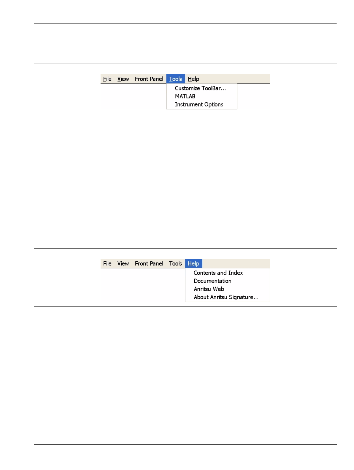
Instrument Overview Graphical User Interface Overview
Tools
The Tools drop-down menu provides access to the Customize Tool Bar dialog and MATLAB. The Tools
drop-down menu can be quickly accessed using the Alt-T keyboard combination.
Figure 3-11. Tools Drop-down Menus
Customize ToolBar...
This menu selection opens the Configure Toolbar dialog. Refer to “Customize Tool Bar Dialog” on page 456 for information about configuring the tool bar.
MATLAB
This menu selection opens the MATLAB dialog. Refer to Signature MathWorks Connectivity Description
on page 6-1 for information about using MATLAB.
Instrument Options
This menu selection opens the Options dialog, which displays the options list and indicates which
options are installed. Refer to Analyzer Configuration on page 2-9 for information about installing new
options.
Help
The Help drop-down menu provides access to the Signature Help System, system updates, technical
support, and the “About Anritsu Signature...” dialog. The Help drop-down menu can be quickly accessed
using the Alt-H keyboard combination.
Figure 3-12. Help Drop-down Menus
Contents and Index
This menu selection provides quick access to the navigation pane of the Signature Help System. This
navigation pane also provides a text based search feature to help you find information within the Help
system.
Documentation
This menu selection opens Windows Explorer to the directory where product support documentation can
be found.
Anritsu Web
This menu selection opens Internet Explorer to the Anritsu Web site, if an internet connection is
available.
MS278XB OM 3-15
Page 68
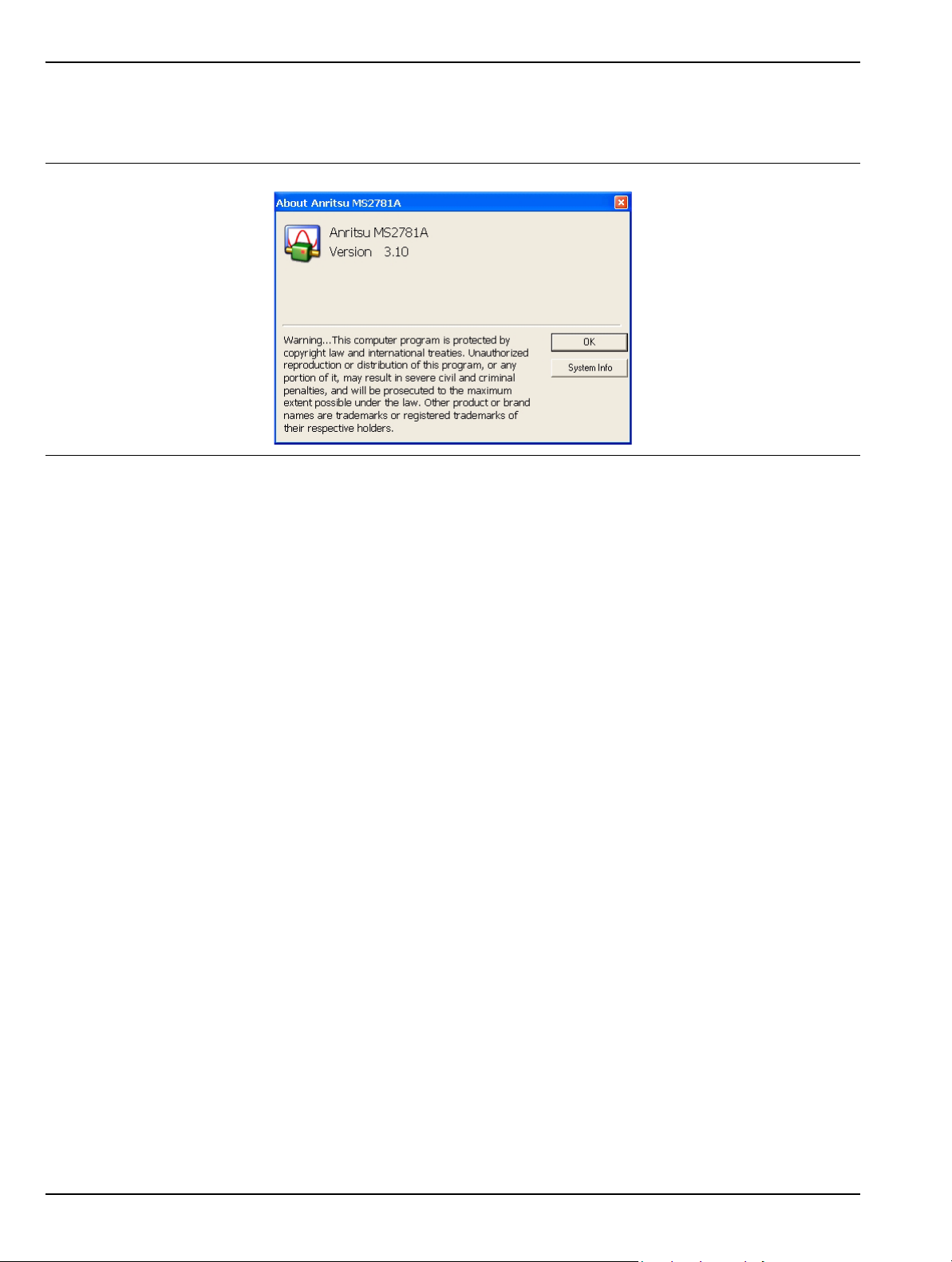
Graphical User Interface Overview Instrument Overview
About Anritsu Signature
The About Anritsu Signature dialog contains information about the analyzer’s software, provides a legal
disclaimer, and offers a link to the Window’s system information file.
Figure 3-13. Help | About Dialog
3-16 MS278XB OM
Page 69
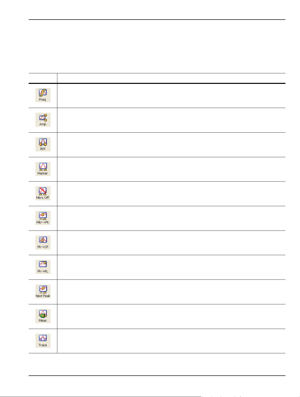
Instrument Overview Graphical User Interface Overview
Main Menu Bar
The Main Menu bar contains a set of icons that access the analyzer’s measurement and setup configuration
sub-menus. Pressing an icon will refresh the sub-menu tree with the related set of sub-menus. The Main Menu
bar can also be customized to display the icons you use most often. Each available icon is detailed in Table 3-5,
below:
Table 3-5. Main Menu Bar Icon List
Icon Description
The Frequency icon opens the “Frequency Main Menu” on page 4-4.
The Amplitude icon opens the “Amplitude Main Menu” on page 4-7.
The Bandwidth icon opens the “Bandwidth Main Menu” on page 4-10.
The Marker icon opens the “Marker Main Menu” on page 4-13.
The Mkrs Off icon turns off all of the markers.
The Mkr->Pk icon turns on the active marker (if no active markers are on) and sends the current
active marker to the trace peak.
The Pk->CF icon turns on the active marker (if no active markers are on), sends the current active
marker to the trace peak, and changes the center frequency of the sweep to the trace peak frequency
value.
The Pk->RL icon turns on the active marker (if no active markers are on), sends the current active
marker to the trace peak, and changes the reference level of the graticule to the trace’s peak
amplitude value.
The Next Peak icon turns on the active marker (if no active markers are on) and sends the current
active marker to the trace peak (or to the next trace peak if the active marker is already on).
The Measurement icon opens the “Measurement Main Menu” on page 4-19.
The Trace icon opens the “Trace Main Menu” on page 4-23.
MS278XB OM 3-17
Page 70

Graphical User Interface Overview Instrument Overview
Table 3-5. Main Menu Bar Icon List
Icon Description
The Sweep icon opens the “Sweep Main Menu” on page 4-27.
The Zero Span icon sets the span to zero span.
The Last Span icon recalls the previous span setting.
The Trigger icon opens the “Trigger Main Menu” on page 4-29.
Use the File icon to open and save instrument setups and configurations. See “File Main Menu” on
page 4-35
Use the Print icon to send the graticule display, setup and co nfiguration files, or mea surement data to
the printer.
The Preset icon presets the instrument.
The System icon opens the “System Main Menu” on page 4-31.
The Help icon accesses the Signature Help system. Press this icon to enable context sensitive help
and to display help topics in the graph area. Press the Help icon again to toggle the display back to
the measurement data.
The MATLAB icon accesses the “MATLAB Setup Dialog” on page 4-57.
3-18 MS278XB OM
Page 71
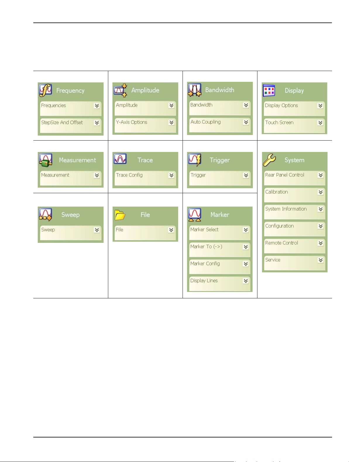
Instrument Overview Graphical User Interface Overview
Sub-menu Trees
After pressing one of the Main Menu icons, the main menu tree is updated with the related sub-menus. Each
sub-menu and its related functions are documented in Chapter 4. A comprehensive list of menus is shown in
Figure 3-14, below:
Frequency Menu Amplitude Menu Bandwidth Menu Display Menu
Measure Menu Trac e Menu Trigger Menu System Menu
Sweep Menu File Menu Marker Menu
Figure 3-14. Graphical List of Menus
Only one sub-menu can be expanded as needed by pressing the sub-menu header. When a new sub-menu is
expanded, the previous sub-menu automatically collapses. The sub-menus have a generalized behavior that is
common throughout the system. This behavior is described in the following paragraphs for each type of menu
control.
Entering Data and Fly-out Menus
Data parameter entry fields, such as center frequency or reference level, are accessed by pressing in the
parameter field. Pressing in a parameter field makes it active and is indicated by a shaded background
with a blinking cursor. When new menus are accessed, the default parameter field is automatically made
active. The active parameter field’s value can be incremented by using the rotary knob for fine steps or
the increment keys for coarse steps that follow the 1, 2, 3, 5 convention. Numerical data can also be
entered directly by using the keypad once the parameter field is made active.
When data is entered, a Fly-out menu flies out offering a variety of appropriate units, selections, or a
terminator operation, such as Enter or Cancel. Fly-out menus work in conjunction with the main menu
area and in some dialog boxes.
MS278XB OM 3-19
Page 72

Graphical User Interface Overview Instrument Overview
Figure 3-15 below illustrates the terminator fly-out menus that you may encounter when entering data:
Power Terminator Frequency Terminator Time Te rminator Enter Terminator
Figure 3-15. Terminator Fly-out Menus
Figure 3-16, below, illustrates most of the selection fly-out menus that you may encounter when entering
data:
RF Measurements Measurements Active Traces Active Markers Sweep Modes
Figure 3-16. Selection Fly-out Menus
3-20 MS278XB OM
Page 73
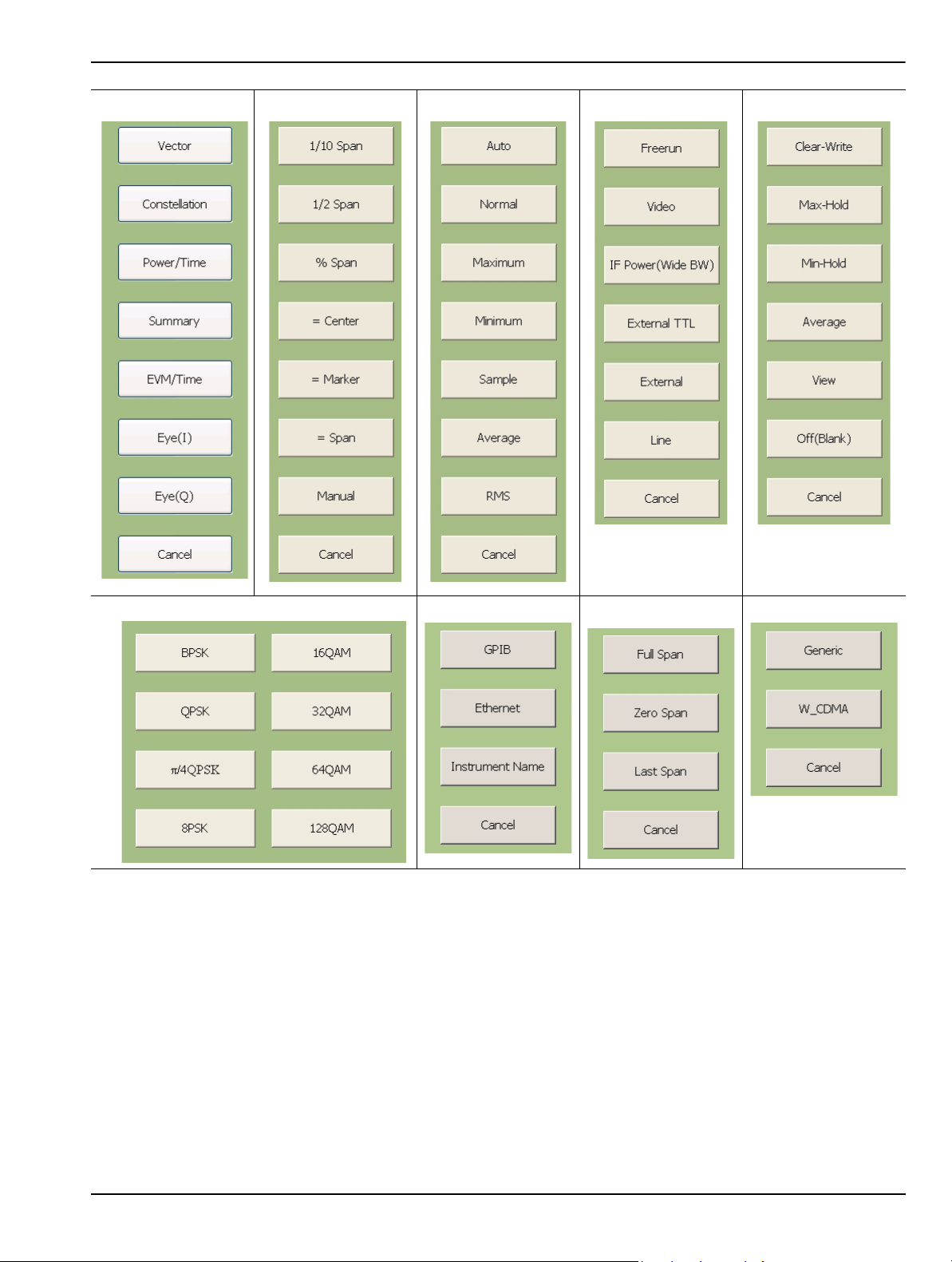
Instrument Overview Graphical User Interface Overview
Modulation Graphs CF Step Sizes Detector Types Trigger Sources Trace States
Modulation Types
Figure 3-16. Selection Fly-out Menus
I/O Configuration Span Presets Standards
MS278XB OM 3-21
Page 74
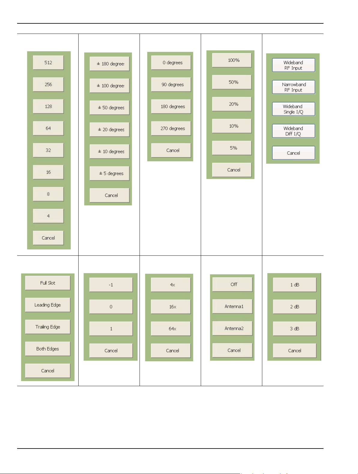
Graphical User Interface Overview Instrument Overview
Constellation
Spreading Factor Phase Error
Rotation Magnitude Scale Input
RACH/TCP Command Pattern CDP Zoom Factor Transmit Diversity
Figure 3-16. Selection Fly-out Menus
Transmit Power
Step Size
3-22 MS278XB OM
Page 75
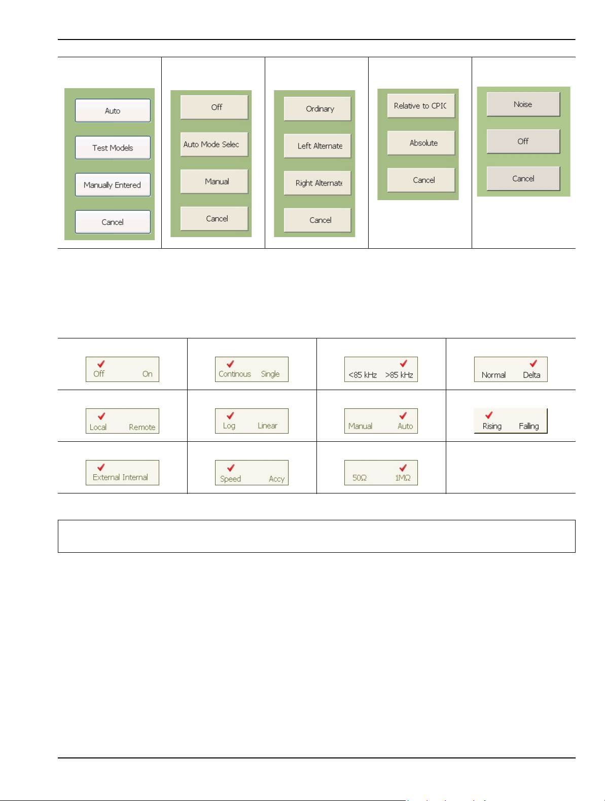
Instrument Overview Graphical User Interface Overview
Active Code
Channels Compressed Mode Scramble Code Code Domain Power Marker Functions
Figure 3-16. Selection Fly-out Menus
Toggle Buttons
Several menus offer a simple on/off type of mode selection. When these controls are present, there is a
check mark indicating the current selection. To toggle the selection to the other mode, press on the
control button. Figure 3-17 below illustrates the toggle buttons that you may encounter in menus:
Figure 3-17. Toggle Buttons
Note: Control buttons that appear greyed out do not have functionality. This occurs when the function is not
appropriate for the particular instrument setup or mode of operation.
MS278XB OM 3-23
Page 76
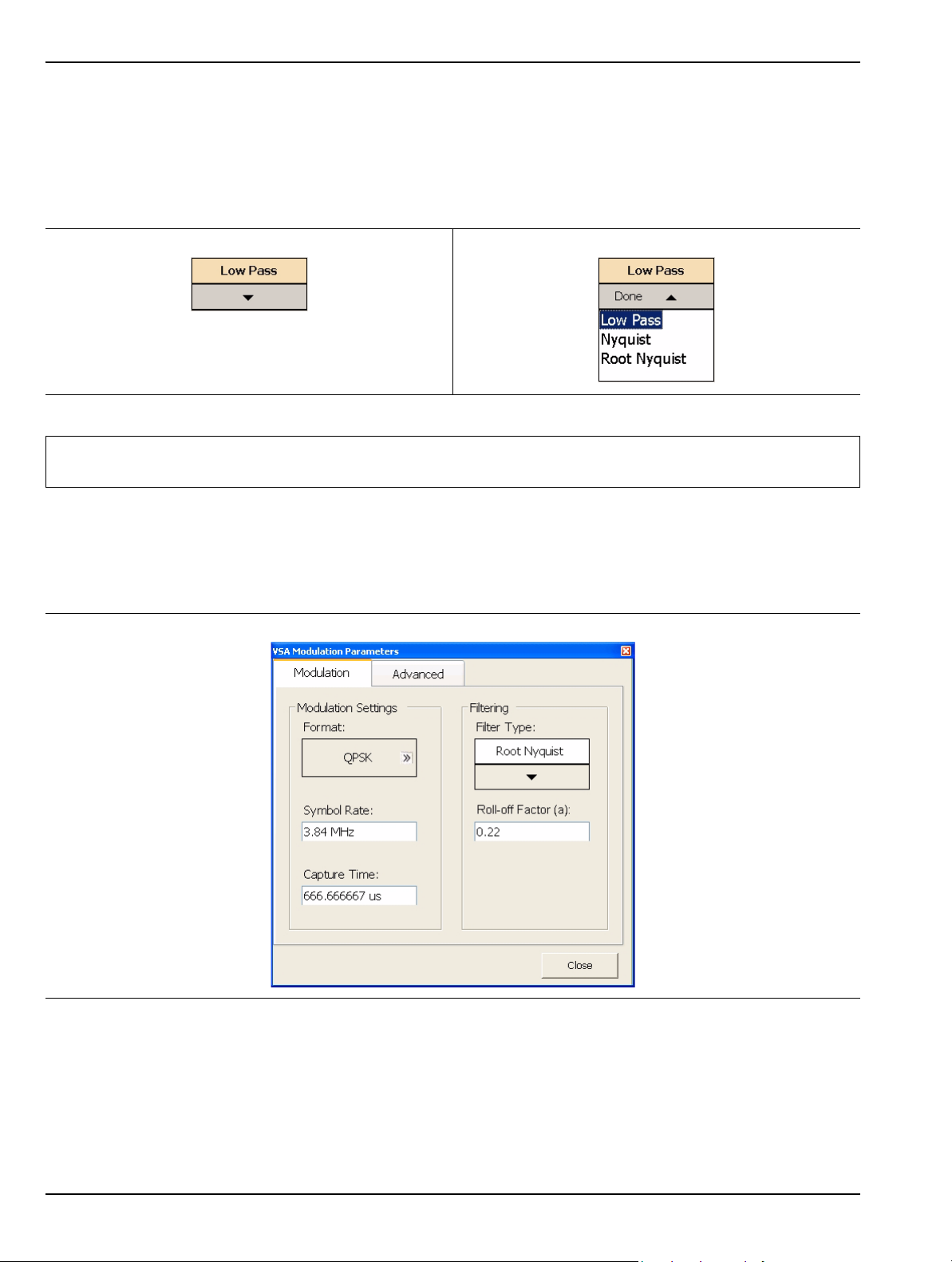
Graphical User Interface Overview Instrument Overview
Drop-down Selection Menus
Many menus offer drop-down selections that contain a variety of choices. To access a drop-down selection
menu, press on the down arrow for the parameter you would like to change and the drop-down selections
will expand. To make a selection, press on one of the choices, then press Done. The current selection is
highlighted at the top of the drop-down selection menu. Figure 3-18 below illustrates a drop-down
selection menu:
Figure 3-18. Drop-down Selection Menu
Note: A selection may also be entered with a rapid double press of the selection or by highlighting the selection,
then pressing the Enter key on the front panel or keyboard.
Parameter Entry and Measurement Setup Dialogs
Parameter entry and measurement setup dialogs are used throughout the system to provide direct access to
related parameters for a given context. These dialogs will generally look like the one shown in Figure 3-19,
below.
Figure 3-19. Parameter Entry and Measurement Setup Dialog
Not all parameters are set by using dialogs. Only those functions that have a complex set of parameters to set
use dialogs. Most SPA functions use parameter entry fields and buttons in the sub-menu display to set their
measurement parameters. Many VSA functions use dialogs to set their measurement parameters. Refer to
“Parameter Entry and Measurement Setup Dialog Archive” on page 4-36 for more information.
3-24 MS278XB OM
Page 77

Instrument Overview Graphical User Interface Overview
Alpha-Numeric Entry
Alphanumeric entry can be accomplished through an external physical keyboard or through the on-screen
software keyboard. Figure 3-20 shows the on-screen keyboard interface.
Figure 3-20. MS278XB On-Screen Keyboard
The on-screen keyboard functions the same as most common keyboards. You simply press the key that you
want to enter. Additional settings are available through the drop-down menus on the keyboard interface
window. The on-screen keyboard is accessed through the Windows Taskbar (View | Taskbar) by pressing:
Start | Programs | Accessories | Accessibility | On-Screen Keyboard
MS278XB OM 3-25
Page 78

Graphical User Interface Overview Instrument Overview
Graticule
The Graph area is the main container for all of the measurement displays. The primary element in this area is
the trace data on a graticule display. Annotations provide feedback on the instrument’s hardware setup for the
measurement as well as measurement related warnings and status messages outside of the graticule area.
Spectral Analysis Graticule Displays
Figure 3-21 shows a typical display while in the spectral analysis mode. Most of the informational
annotations are indicated. Table 3-6 provides a detailed description of each of the display elements.
Figure 3-21. Spectral Analysis Graticule
3-26 MS278XB OM
Page 79

Instrument Overview Graphical User Interface Overview
Table 3-6. Spectral Analysis Graticule Legend
Index Description
Status Indicator: This indicator (asterisk) is displayed when the current instrument setup does not
correspond to the one which was applied when a trace is displayed. This happens when:
1
2 Y-axis Scale: The Y-axis scale is labeled every other major grid line.
3 Sweep Status: Displays the sweep status of Triggered and Single sweep modes.
4 to 8
9
10 Start Frequency: Indicates the start frequency of the sweep.
11 Frequency/Division: This field indicates the horizontal scaling per division.
12
13 Span Frequency: Indicates the total span of the frequency sweep.
14 Stop Freq ue n cy : Indic at es th e sto p freque n cy of the swe ep .
15
16 Marker Display: Markers are annotated with the absolute power level next to the marker location.
17 Marker Display: Markers are annotated with the absolute power level next to the marker location.
18 Display Line: A display line may be displayed at any desired level.
19
20
21
22
The instrument setup is modified when the Sweep mode is set to Single and a n ew sweep has not
yet been triggered.
The instrument setup is modified in the middle of a measurement. The measurement is re -started
with the new setup and this indicator is shown until the entire trace is re-written.
Trace Information: Trace information is displayed in the following format (the current active trace has
the text underlined):
Trc<n> <Trace Mode>
<Detector Mode>
<Trace Math>
Where:
n: Trace Number (1 to 5)
Trace Mode: Trace Mode (Clear Write, Max Hold, Min Hold, Average, View, or Off)
Detector: Detector Type (Auto, Normal, Maximum, Minimum, Sample, Average, or RMS)
Trace Math: Trace Math indicator (available when Trace Mode: Average is selected)
Sweep Mode: This field is used to display the sweep modes of Swept, FFT ( Fast Fourier Transform), or
FFT-WB (Wideband).
Center Frequency: Indicates the center frequency of the sweep. If a freq uency offset is set, OFFSET is
also displayed.
Trace Display: Up to five traces can be displayed using the following colors: Trace 1--Yellow, Trace 2-Green, Trace 3--Cyan, Trace 4--Magenta, Trace 5--Red
Active Marker Field: The active marker number, frequency, and amplitude values are displayed in this
field. The trace that has received the marker is indicated in brackets. If the Marker is a Delta Marker , th e
delta symbol (
marker.
Reference Marker Field: The reference marker number, frequency, and amplitude values are displayed
in this field. The displayed values are absolute in magnitude.
Bandwidth Setup: The bandwidth setup field displays the current Resolution Bandwidth, Video
Bandwidth, and Sweep Time settings. If the settings are manually entered, an asterisk is displayed.
Amplitude Setup: The amplitude setup field displays the current attenuation level, reference level, and
reference level offset. If the attenuation is set manually, an asterisk is displayed.
D) precedes the Mkr number and the values displayed are relative to the reference
MS278XB OM 3-27
Page 80
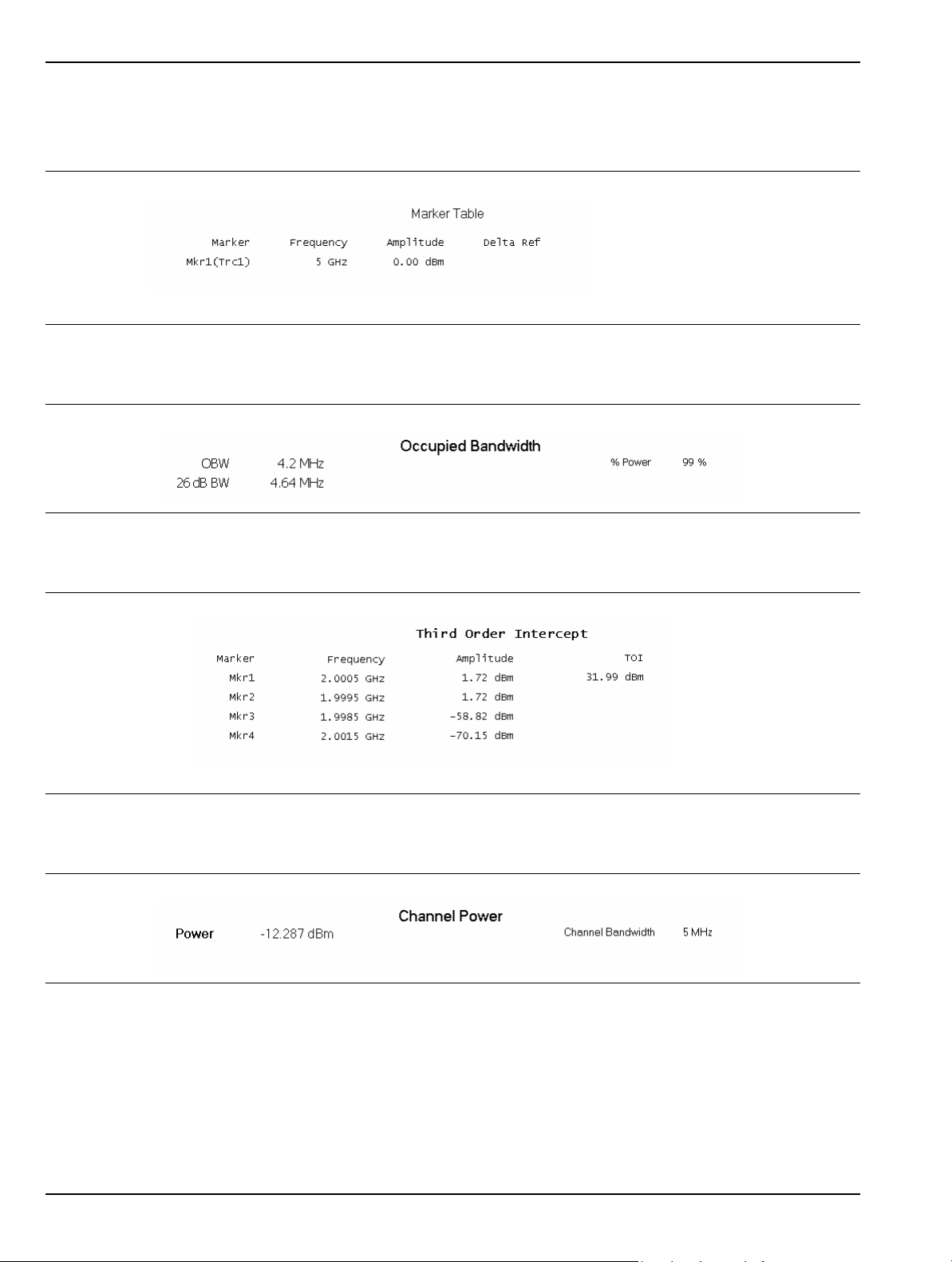
Graphical User Interface Overview Instrument Overview
Data Displays
The following figures (Figure 3-22 to Figure 3-27) show the measurement tables that are displayed for
the one-button RF measurements.
Figure 3-22. Marker Table with Delta and Noise Marker
Figure 3-23. Occupied Bandwidth Measurement Table
Figure 3-24. Third Order Intercept Measurement Table
Figure 3-25. Channel Power Measurement Table
3-28 MS278XB OM
Page 81
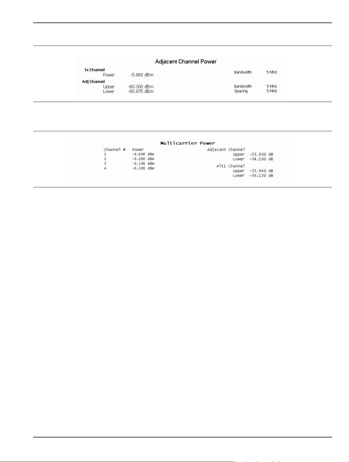
Instrument Overview Graphical User Interface Overview
Figure 3-26. Adjacent Channel Power Measurement Table
Figure 3-27. Multi-Carrier Power Table
MS278XB OM 3-29
Page 82

Graphical User Interface Overview Instrument Overview
Vector Signal Analysis Graticule Displays
Figure 3-28 shows trace data while using the various modulation graph types indicated below:
• Vector Graph Type
• EVM/Time Graph Type
• Constellation Graph Type
• Power/Time Graph Type
• Eye(I) Graph Type
• Eye(Q) Graph Type
Figure 3-28. Vector Signal Analysis Graticule
3-30 MS278XB OM
Page 83
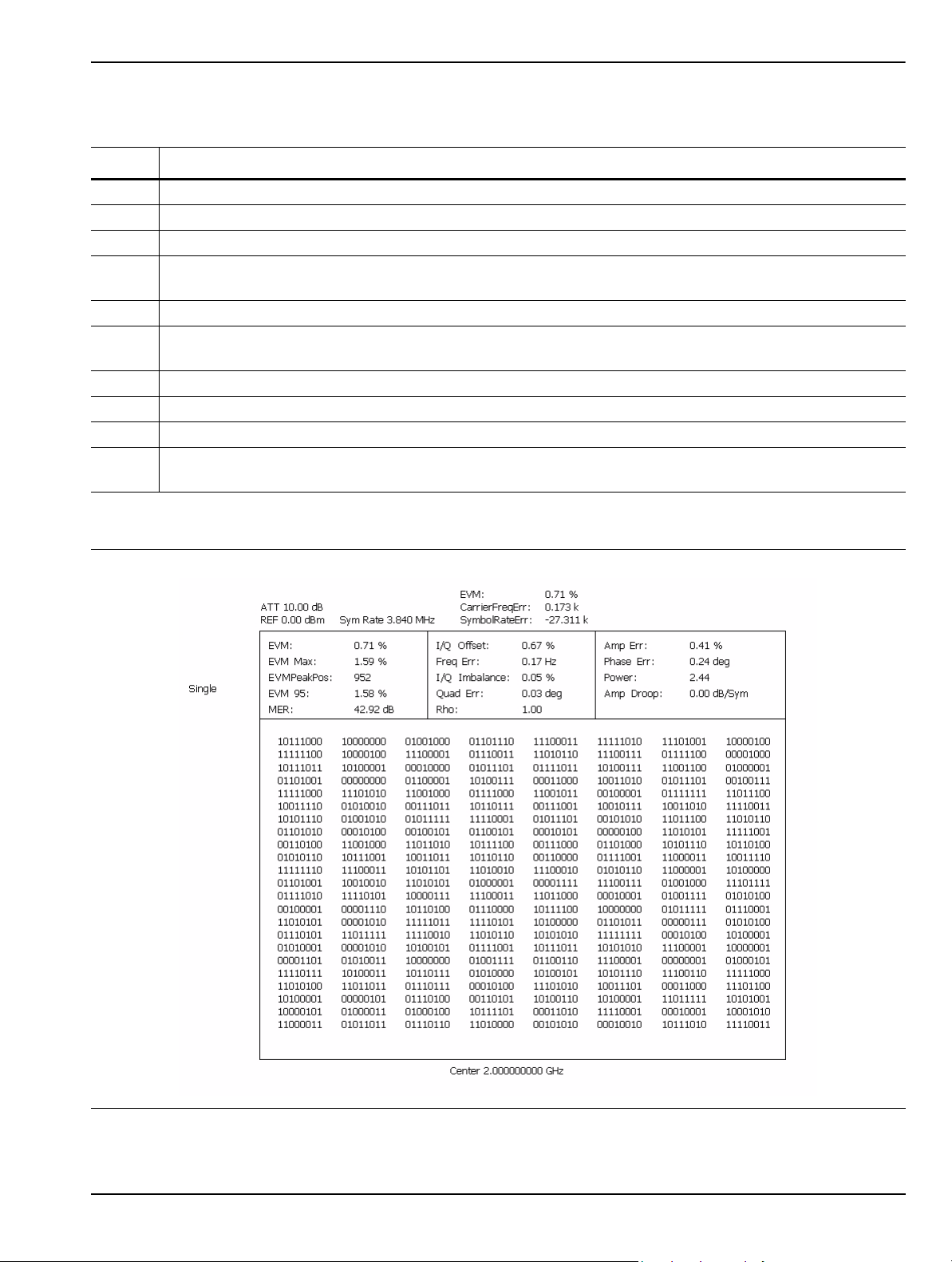
Instrument Overview Graphical User Interface Overview
Table 3-7. Vector Signal Analysis Graticule Legend
Index Description
1 Input Status: Indicates ADC overload and L.O. unlock.
2 Sweep Status: Displays the sweep status of Triggered and Single sweep modes.
3 Trace Display: Vector trace data is displayed in Yellow.
Y-axis Scale: This scale shows the normalized I and Q range when in the Vector, Constellation, Power
4
vs. Time, and Eye graph types; it shows percentage error (%) when in the EVM graph type.
5 X-axis Scale: This field shows the Symbols or Time.
Center Frequency: Indicates the center frequency of the sweep. If a freq uency offset is set, OFFSET is
6
also displayed.
7 Marker Information: Displays the Symbol and I and Q magnitude.
8 Error Data: Displays the error vector magnitude, carrier frequency error, and symbol rate error.
9 Symbol Rate: Displays the current symbol rate
10
Amplitude Setup: The amplitude setup field displays the current attenuation level and reference level. If
the attenuation is set manually, an asterisk is displayed.
The Summary graph type displays the position and value (bits) of the demodulated signal.
Figure 3-29. QPSK Summary Display
MS278XB OM 3-31
Page 84
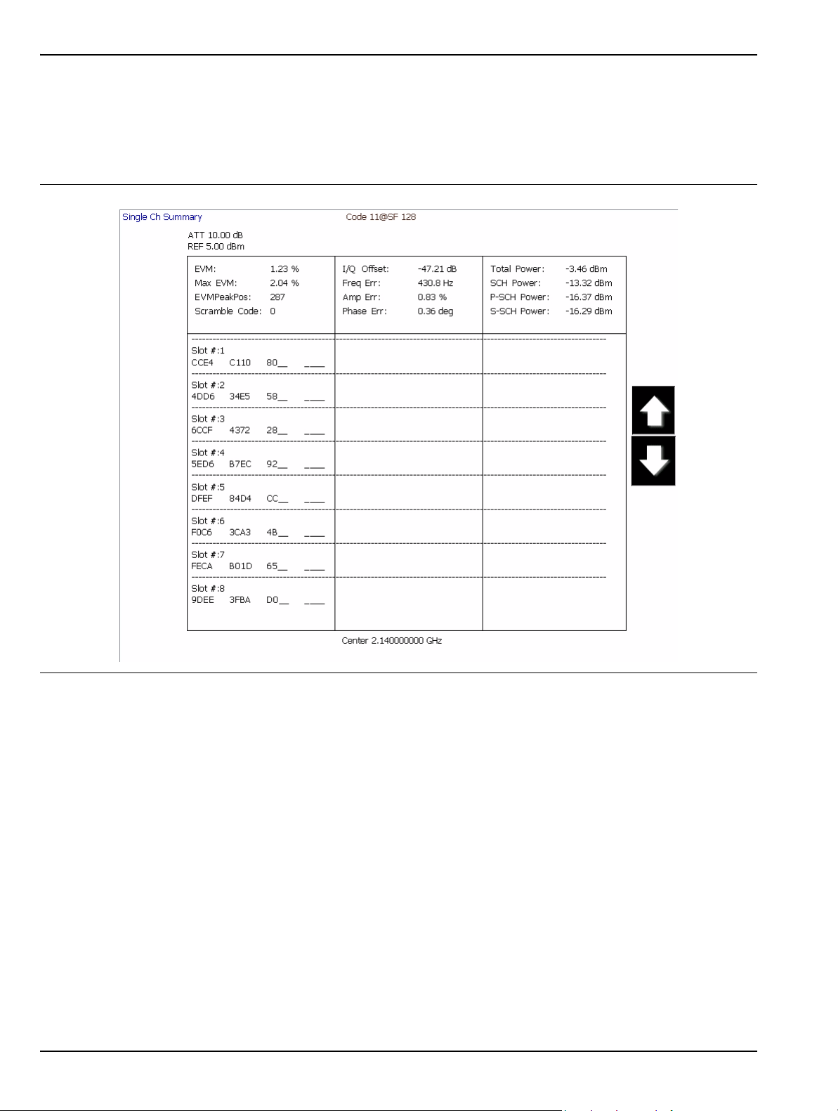
Graphical User Interface Overview Instrument Overview
Figure 3-30 is a summary table showing the key modulation quality measurements and the bit stream for one
of the codes.
Note that the bit stream can be very long in some cases. If you have captured the full 8 slots and have a HighSpeed (HSDPA) signal, there can be many pages of the bit stream. The scroll buttons at the right facilitate
viewing all of this information.
Figure 3-30. Single Code Summary Table
3-32 MS278XB OM
Page 85
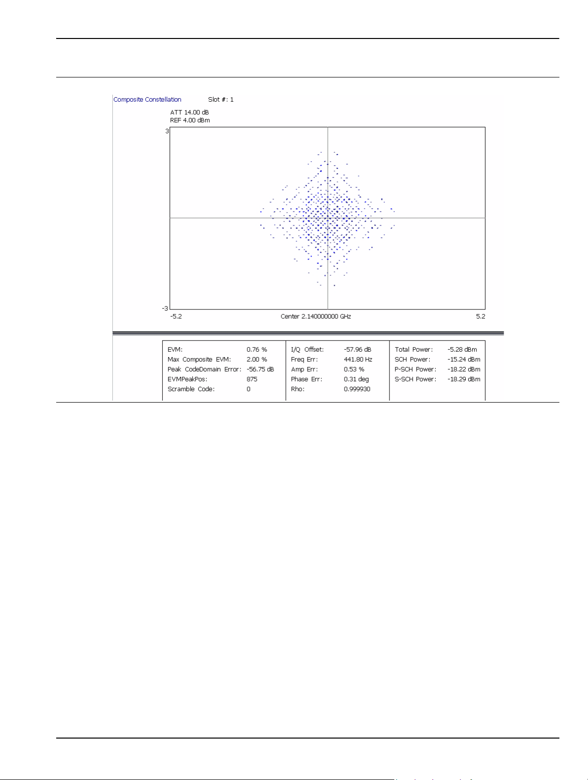
Instrument Overview Graphical User Interface Overview
Signature can also display a variety of data combinations as shown in the following figures.
Figure 3-31. Composite Constellation with Summary Table of Test Model 2
MS278XB OM 3-33
Page 86

Graphical User Interface Overview Instrument Overview
Figure 3-32. Code Domain Power for Test Model 1 with Zoom and Summary Table
For more detail about making modulation measurements and setting up the displays, refer to the appropriate
sections in Chapter 5.
3-34 MS278XB OM
Page 87

Instrument Overview Graphical User Interface Overview
Instrument Messages and Status Bar
The Status Bar Area is used for instrument wide messages to show Status, Warnings, Errors, etc. Typically,
any warning messages displayed in this area will be shown until you perform some action on the interface.
Error indicators are persistent until you have viewed (and cleared) the error log.
Figure 3-33. Instrument Status Bar
General Status Messages
The status bar indicates the status of items, such as calibration in progress, FFT is in acquisition or
computation, startup, self test, etc. General status messages are displayed in the left field of the status
bar, for example, EXT REF.
Warning Messages
Warning messages are displayed in the center field of the status bar. These messages indicate that there
is an internal error, such as, ERR!
Calibration Messages
If the instrument detects that a calibration needs to be performed, an UNCAL indicator appears in the
status bar. If you click on the message, you are given the option to perform the calibration now or to defer
the action until a later time. If the calibration is performed, the message is cleared.
Note: UNCAL messages may be automatically cleared if the software determines that the instrument becomes
within tolerance.
MS278XB OM 3-35
Page 88

Graphical User Interface Overview Instrument Overview
External Keyboard Hot-key Functions
When the MS278XB is equipped with an external keyboard, additional input is available through various
keyboard combinations (hot keys). Table 3-8 lists the hot keys and their function.
Table 3-8. Keyboard Hot-key Reference
Key
Reference Signature Usage AT-101 Usage
1 Frequency Main Menu Ctrl-Shift-Q
2 Amplitude Main Menu Ctrl-Shift-W
3 Bandwidth Main Menu Ctrl-Shift-E
4 Marker Main Menu Ctrl-Shift-R
5 Measure Main Menu Ctrl-Shift-T
6 Trace Main Menu Ctrl-Shift-A
7 Display Main Menu Ctrl-Shift-S
8 Sweep Main Menu Ctrl-Shift-D
9 Trigger Main Menu Ctrl- Shift-F
10 System Main Menu Ctrl-Shift-G
11 File Main Menu Ctrl-Shift-H
12 Preset Main Menu Ctrl-Shift-P
13 Signature Help System View Toggle Ctrl-Shift-J
14 File Drop Down Menu Alt-F
15 View Drop Down Menu Alt-V
16 Front Panel Drop Down Menu Alt-P
17 Tools Drop Down Menu Alt-T
18 Help Drop Down Menu Alt-H
19 Increment Parameter Up (Coarse) Page Up
20 Increment Parameter Down (Coarse) Page Down
21 Increment Parameter Up (Fine) Up Arrow
22 Increment Parameter Down (Fine) Down Arrow
23 Numeric Keys Numeric Keys
24 Backspace Backspace
25 Escape Esc
26 Enter Enter
3-36 MS278XB OM
Page 89

Instrument Overview Instrument Operation
3-4 Instrument Operation
Changing Setups
When a parameter is changed via the front panel, or a message is received containing new setup information,
the system validates the requested change, and then goes into the “setup” state while the new setup
information is assimilated. When the new setup information is processed, the system returns to the measure
state. You may observe a momentary delay during this process, which is normal.
Calibration State
The system enters a calibration state when you request it or when the system determines that calibration is
necessary. In this calibration state, the analog receiver and LO hardware is calibrated and the results saved
for use in measurement corrections. Upon completion, the system returns to the measure state.
Instrument Preset
The instrument can be set to a known state by pressing the Preset key, or the Preset menu item on the Front
Panel drop-down menu, or by a command via the remote programming interface (GPIB or LAN). When
initiating a preset, the instrument goes through a sequence similar to startup by loading the default
measurement parameters to the hardware.
MS278XB OM 3-37
Page 90
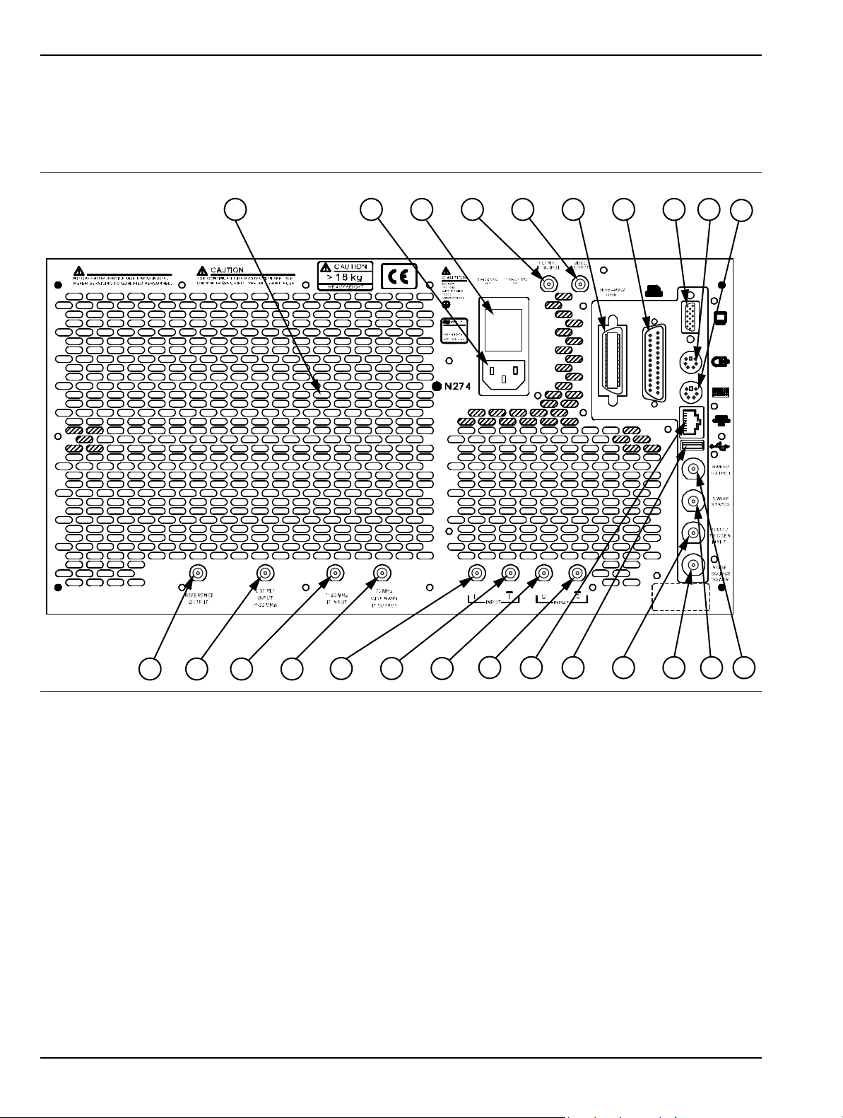
Rear Panel and Connector Diagrams Instrument Overview
1 2 3 4 5 6
7
8
9
10
13 14
19
20 21
22
23
1211
24
15
16 17
18
3-5 Rear Panel and Connector Diagrams
Figure 3-34, below, illustrates the MS278XB’s rear panel features and connectors. Table 3-9, on the following
pages, describes the indices shown, lists Input/Output specifications for each connector, and lists the connector
type. The connector pinout diagrams are illustrated in Table 3-10 through Table 3-16.
Figure 3-34. MS278XB Rear Panel Overlay Drawing
3-38 MS278XB OM
Page 91
Instrument Overview Rear Panel and Connector Diagrams
Table 3-9. MS278XB Rear Panel Index Legend
Index Name/Image Description Connector
Air Exhaust Grill
1
AC Power Input
2
Fuse Block
3
BNC Output
4
The rear panel exhaust grill provides for cooling of the
instruments internal components. Ensure that the exhaust grill is
not blocked.
The ac power input accepts an ac power supply in the range of
85 to 264 V ac, 47 to 63 Hz, a nd 400 VA. The receptacle accepts a
3-pronged power cord, which must be properly gr ounded to a void
the risk of an electric shock.
The MS278XB has two, SLOW BLO fuses with a rating of:
250 V, 6.3 A.
Output is currently not used. BNC
N/A
N/A
N/A
Female
Log Video Out
5
MS278XB OM 3-39
Outputs “Y” data value
2.5V nominal output into 50Ω with full scale signal level displayed
BNC
Female
Page 92
Rear Panel and Connector Diagrams Instrument Overview
Table 3-9. MS278XB Rear Panel Index Legend
Index Name/Image Description Connector
GPIB Interface
6
Parallel Interface
7
IEEE 488 standard 24-pin connector that provides for remotely
controlling the MS278XB from an external computer/controller via
the IEEE-488 bus (GPIB). Table 3-10 describes the signal lines
and shows the connector pinout.
25-pin connector that provides a parallel interface to an external
printer. Table 3-11 describes the signal lines and shows the
connector pinout.
Interface is currently not available.
IEEE 488.2
25-pin
D-Sub
Monitor Interface
8
PS/2 Mouse
Interface
9
3-40 MS278XB OM
15-pin XGA connector allows the MS278XB to send the front
panel touch screen display to an external VGA/XGA monitor.
Table 3-13 describes the signal lines and shows the connector
pinout.
Provides connection to an external PS/2 mouse. 6-pin
15-pin
D-Sub
DIN
Page 93
Instrument Overview Rear Panel and Connector Diagrams
Table 3-9. MS278XB Rear Panel Index Legend
Index Name/Image Description Connector
10
11
12
13
PS/2 Keyboard
Interface
Reference Output
Reference Input
External IF Input
Provides connection to an external PS/2 keyboard. 6-pin
DIN
Provides a reference frequency output
Using the internal 10 MHz reference:
Level: 8 dBm ± 3 dB
Frequency: 10 MHz
Using an external frequency reference:
Level: –19 dBm to –14 dBm
Frequency: Same as external frequency
Provides a reference frequency input
Level: –6 dBm < input signal < +10 dBm
Frequency: Any frequency from 1 to 25 MHz with
1 MHz resolution and 1.544 or 2.048 MHz
1128.65 MHz input for VSA, mixer, etc. SMA
BNC
Female
BNC
Female
Female
14
15
16
17
IF Output
I Input
I
Input
Q Input
Outputs 75 MHz IF
Level: –5 dBm ± 5 dB
BW: > 40 MHz (>120 MHz without image rejection filter)
Differential input for baseband I/Q
50Ω or 1MΩ
Switchable unbalanced or differential
1 Volt max
differential input for baseband I/Q
VSA I
50Ω or 1 MΩ
Switchable unbalanced or differential
1 Volt max
VSA Q differential input for baseband I/Q
50Ω or 1 MΩ
Switchable unbalanced or differential
1 Volt max
BNC
Female
BNC
Female
BNC
Female
BNC
Female
MS278XB OM 3-41
Page 94
Rear Panel and Connector Diagrams Instrument Overview
Table 3-9. MS278XB Rear Panel Index Legend
Index Name/Image Description Connector
18
19
20
21
22
Input
Q
Ethernet
USB
Trig/Gate Input
Noise Source Power
VSA Q
50Ω or 1 MΩ
Switchable unbalanced or differential
1 Volt max
10BASE-T, 100BASE-TX with LED indicators
Depending on network connection and activity:
Amber LED indicates power
Green LED indicates communication
USB serial bus interface
Version 2.0
Logic input for sweep control
+10V to –10V
10 kΩ
Provides power for an external noise source
+28V ±2V
100 mA
Software enabled
differential input for baseband I/Q
BNC
Female
8-pin
RJ45
USB 4-pin
Type A
BNC
Female
BNC
Female
23
24
Sweep Status
Sweep Output
Logic output for sweep control
TTL active LOW when sweeping
Output is currently not used BNC
BNC
Female
Female
3-42 MS278XB OM
Page 95
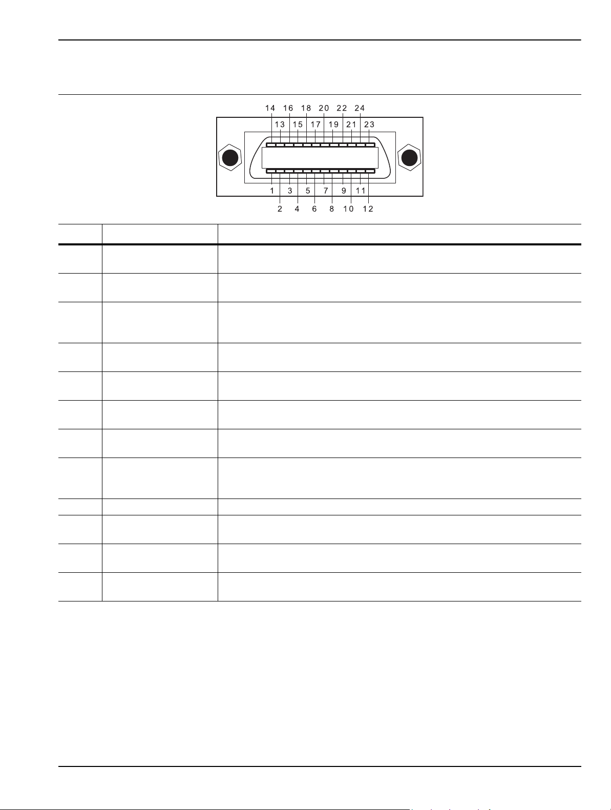
Instrument Overview Rear Panel and Connector Diagrams
Table 3-10. Index 6: IEEE 488.2 GPIB Connector Pinout Diagram
Pin Name Description
1-4 DIO 1 through DIO 4
5EOI
6DAV
7NRFD
8NDAC
9IFC
10 SRQ
11 ATN
12 Shield Ground Point.
13-16 DIO 5 through DIO 8
17 REN
18 to
24
GND
Data Input/Output. Bits are HIGH when the data is logical 0 and LOW when the
data is logical 1.
End or Identify. A low-true state indicates that the last byte of a multi byte
message has been placed on the line.
Data Valid. A low-true state indicates th at the talker has (1) sensed that NRFD
is LOW, (2) placed a byte of data on the bus, and (3) waited an appropriate
length of time for the data to settle.
Not Ready For Data. A high-true state indicates that valid data has not yet
been accepted by a listener.
Not Data Accepted. A low-true state indicates that the current data byte has
been accepted for internal processing by a listener.
Interface Clear. A low-true state places all bus instruments in a known state—
such as, unaddressed to talk, unaddressed to listen, and service request idle.
Service Request. A low-true state indicates that a bus instrument needs
service from the controller.
Attention. A low-true state enables the controller to respond to both its own
listen/talk address and to appropriate interface messages—such as, device
clear and serial poll.
Data Input/Output. Bits are high with the data is logical 0 and LOW when the
data is logical 1.
Remote Enable. A low-true state enables bus instruments to be operated
remotely, when addressed.
Logic ground.
MS278XB OM 3-43
Page 96
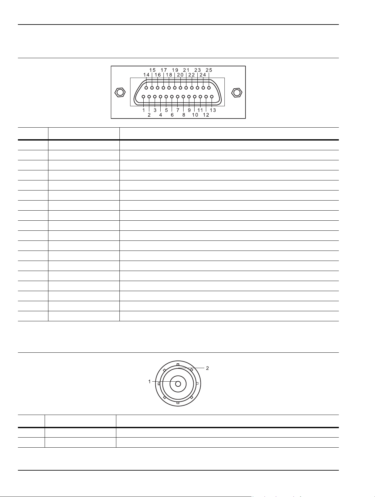
Rear Panel and Connector Diagrams Instrument Overview
Table 3-11. Index 7: 25-pin Parallel Printer Connector Pinout Diagram
Pin Name Description
1 Strobe Strobe signal drops TTL low when data is being sent to printer
2 Data0 Data signal to printer
3 Data1 Data signal to printer
4 Data2 Data signal to printer
5 Data3 Data signal to printer
6 Data4 Data signal to printer
7 Data5 Data signal to printer
8 Data6 Data signal to printer
9 Data7 Data signal to printer
10 Acknowledge Acknowledge signal drops TTL low when data is received by printer
11 Busy TTL high when printer is busy
12 Paper End TTL high when printer is out of paper
13 Select TTL high signals that the printer is online
14 Auto Feed TTL high signals an auto feed
15 Error TTL low signals a printer error
16 Init TTL low initializes the printer
17 Select In TTL high sets printer offline
18 to 25 Ground Electrical reference ground
Table 3-12. Indexes 4,5, 11 to 18, and 21 to 24: BNC Connector Pinout Diagram
Pin Name Description
1 Center Pin Carries data or signal
2 Shield Ground return or shield
3-44 MS278XB OM
Page 97
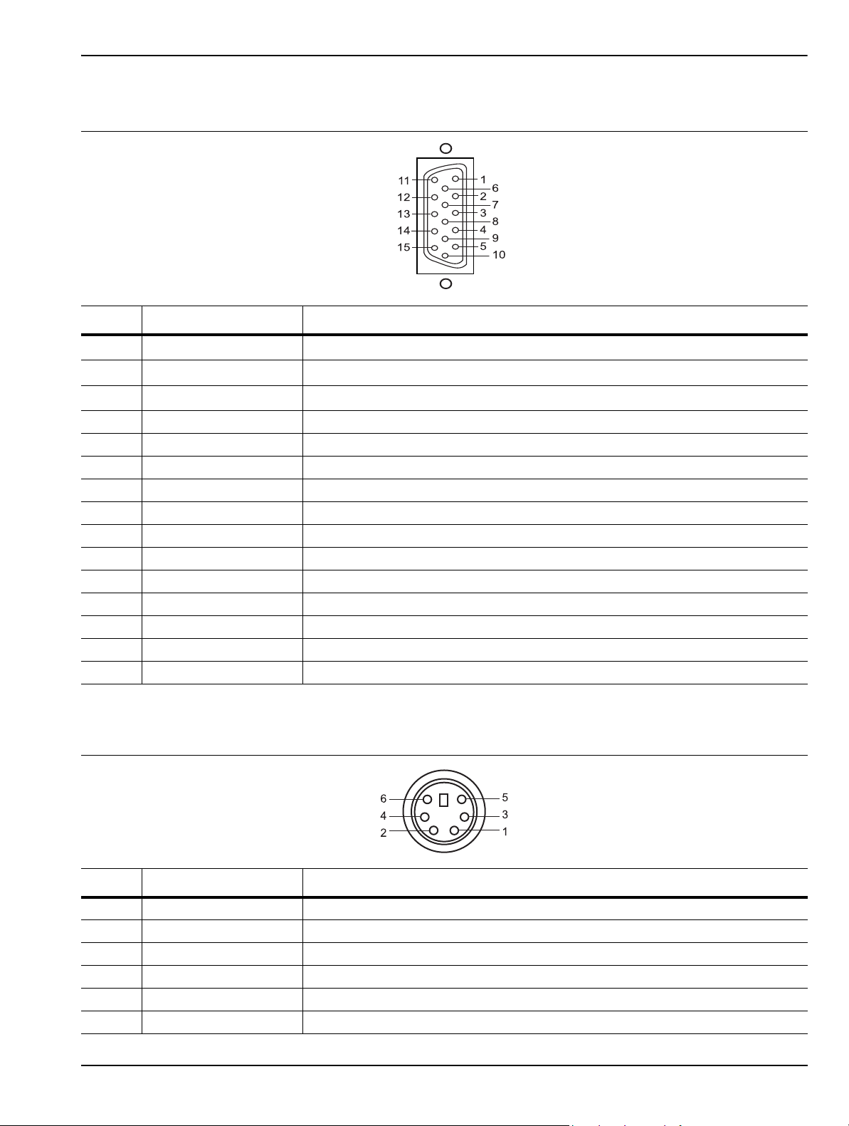
Instrument Overview Rear Panel and Connector Diagrams
Table 3-13. Index 8: 15-pin XGA Connector Pinout Diagram
Pin Name Description
1Red
2Green
3Blue
Red Video (75 Ω, 0.7 V
Green Video (75 Ω, 0.7 V
Blue Video (75 Ω, 0.7 V
p-p
p-p
)
p-p
)
)
4 ID2 Monitor ID Bit 2
5 GND Ground
6 RGND Red Ground
7 GGND Green Ground
8 BGND Blue Ground
9 Key Connector Orientation Key
10 SGND Sync Ground
11 ID0 Monitor ID Bit 0
12 ID1 Monitor ID Bit 1
13 Hsync Horizontal Sync
14 Vsync Vertical Sync
15 ID3 Monitor ID Bit 3
Table 3-14. Index 9 and 10: 6-pin PS2 Mouse and Keyboard Connector Pinout Diagram
Pin Name Description
1 Data Data signals from mouse or keyboard
2 – Not used
3 GND Ground
4 VCC +5 volts, 500 mA
5 Clock Sent data clock
6 – Not used
MS278XB OM 3-45
Page 98
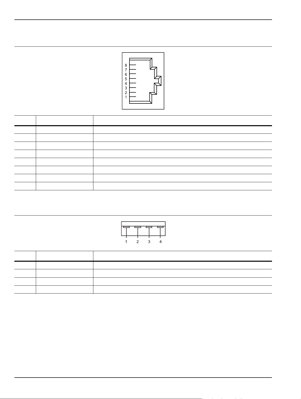
Rear Panel and Connector Diagrams Instrument Overview
Table 3-15. Index 19: 8-pin Ethernet RJ45 Connector Pinout Diagram
Pin Name Description
1 TX+ Transmit data (> +3 volts)
2 TX– Transmit data (< –3 volts)
3 RX+ Receive data (< –3 volts)
4 – Not used (common mode termination)
5 – Not used (common mode termination)
6 RX– Receive data (< –3 volts)
7 – Not used (common mode termination)
8 – Not used (common mode termination)
Table 3-16. Index 20: 4-pin USB Type A Connector Pinout Diagram
PIN Name Description
1 VCC +5 volts, 500 mA
2 –Data Data input
3 +Data Data output
4 GND Ground
3-46 MS278XB OM
Page 99

Chapter 4 — Front Panel Menus
4-1 Introduction
This chapter provides a comprehensive collection of annotated front panel menus and displays. Each
illustration is accompanied with a description that includes information on how to use the functions available
in that particular display. Additional navigation options and techniques may also be provided; however, this
chapter does not provide measurement concepts. For details on making measurements, refer to Chapter 5.
4-2 Quick Reference
This section contains a comprehensive list of menus with references to the page where a full description can be
found. Table 4-1 contains a list of main menus and submenus; Table 4-2 contains a list of property sheets and
dialog menus.
Table 4-1. List of Menus
Main Menu Submenu Page
Frequency Main Menu
Amplitude Main Menu
Bandwidth Main Menu
Marker Main Menu
Measurement Main Menu Measurement Menu 4-20
Trace Main Menu Trace Config Menu 4-24
Display Main Menu
Sweep Main Menu Sweep Menu 4-28
Trigger Main Menu Trigger Menu 4-30
System Main Menu
File Main Menu File Menu 4-35
Frequencies Menu 4-5
Step Size and Offset Menu 4-6
Amplitude Menu 4-8
Y-Axis Options Menu 4-9
Bandwidth Menu 4-11
Auto Coupling Menu 4-12
Marker Select Menu 4-14
Marker to (–>) Menu 4-17
Marker Config Menu 4-18
Display Lines Menu 4-18
Display Options Menu 4-26
Touch Screen Menu 4-26
Rear Panel Control Menu 4-32
Calibration Menu 4-32
System Information Menu 4-32
Configuration Menu 4-33
Remote Control Menu 4-33
Service Menu 4-34
MS278XB OM 4-1
Page 100
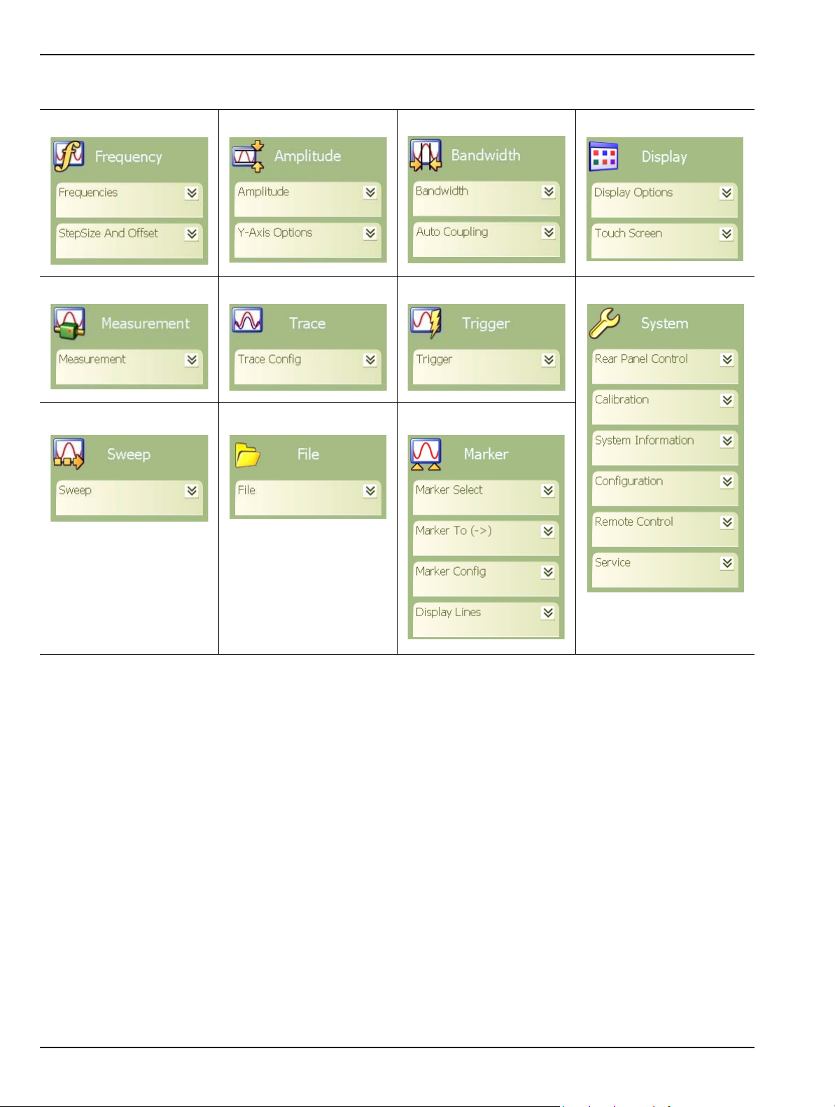
Quick Reference Front Panel Menus
Frequency Menu Amplitude Menu Bandwidth Menu Display Menu
Measure Menu Trace Menu Trigger Menu System Menu
Sweep Menu File Menu Marker Menu
Figure 4-1. Graphical List of Menus
4-2 MS278XB OM
 Loading...