

Page 1

Maintenance Manual
Site Master Spectrum Analyzer
MS2711B
Handheld Spectrum Analyzer for Measuring, Monitoring, and
Analyzing Signal Environments
Anritsu Company
490 Jarvis Drive
Morgan Hill, CA 95037-2809
USA
P/N: 10580-00072
Revision: C
Copyright 2009 Anritsu Company
Printed: June 2009
Page 2

WARRANTY
The Anritsu product(s) listed on the title page is (are) warranted against defects in materials and workmanship for
three years from the date of shipment.
Anritsu’s obligation covers repairing or replacing products which prove to be defective during the warranty period.
Buyers shall prepay transportation charges for equipment returned to Anritsu for warranty repairs. Obligation is
limited to the original purchaser. Anritsu is not liable for consequential damages.
LIMITATION OF WARRANTY
The foregoing warranty does not apply to Anritsu connectors that have failed due to normal wear. Also, the warranty
does not apply to defects resulting from improper or inadequate maintenance by the Buyer, unauthorized
modification or misuse, or operation outside of the environmental specifications of the product. No other warranty is
expressed or implied, and the remedies provided herein are the Buyer’s sole and exclusive remedies.
DISCLAIMER OF WARRANTY
DISCLAIMER OF WARRANTIES. TO THE MAXIMUM EXTENT PERMITTED BY APPLICABLE LAW, ANRITSU
COMPANY AND ITS SUPPLIERS DISCLAIM ALL WARRANTIES, EITHER EXPRESS OR IMPLIED,
INCLUDING, BUT NOT LIMITED TO, IMPLIED WARRANTIES OF MERCHANTABILITY AND FITNESS FOR A
PARTICULAR PURPOSE, WITH REGARD TO THE SOFTWARE PRODUCT. THE USER ASSUMES THE ENTIRE
RISK OF USING THE PROGRAM. ANY LIABILITY OF PROVIDER OR MANUFACTURER WILL BE LIMITED
EXCLUSIVELY TO PRODUCT REPLACEMENT.
NO LIABILITY FOR CONSEQUENTIAL DAMAGES. TO THE MAXIMUM EXTENT PERMITTED BY
APPLICABLE LAW, IN NO EVENT SHALL ANRITSU COMPANY OR ITS SUPPLIERS BE LIABLE FOR ANY
SPECIAL, INCIDENTAL, INDIRECT, OR CONSEQUENTIAL DAMAGES WHATSOEVER (INCLUDING,
WITHOUT LIMITATION, DAMAGES FOR LOSS OF BUSINESS PROFITS, BUSINESS INTERRUPTION, LOSS
OF BUSINESS INFORMATION, OR ANY OTHER PECUNIARY LOSS) ARISING OUT OF THE USE OF OR
INABILITY TO USE THE SOFTWARE PRODUCTS, EVEN IF ANRITSU COMPANY HAS BEEN ADVISED OF
THE POSSIBILITY OF SUCH DAMAGES. BECAUSE SOME STATES AND JURISDICTIONS DO NOT ALLOW
THE EXCLUSION OR LIMITATION OF LIABILITY FOR CONSEQUENTIAL OR INCIDENTAL DAMAGES, THE
ABOVE LIMITATION MAY NOT APPLY TO YOU.
TRADEMARK ACKNOWLEDGMENTS
Windows, Windows XP, Microsoft Paint, Microsoft Word, Microsoft Access, Microsoft Excel, Microsoft PowerPoint,
and Visual Studio are all registered trademarks of Microsoft Corporation.
Acrobat Reader is a registered trademark of Adobe Corporation.
MATLAB is a a registered trademark of The MathWorks Corporation.
NI is a trademark of the National Instruments Corporation.
Signature is a trademark of Anritsu Company.
NOTICE
Anritsu Company has prepared this manual for use by Anritsu Company personnel and customers as a guide for the
proper installation, operation and maintenance of Anritsu Company equipment and computer programs. The
drawings, specifications, and information contained herein are the property of Anritsu Company, and any
unauthorized use or disclosure of these drawings, specifications, and information is prohibited; they shall not be
reproduced, copied, or used in whole or in part as the basis for manufacture or sale of the equipment or software
programs without the prior written consent of Anritsu Company.
UPDATES
Updates, if any, can be downloaded from the Documents area of the Anritsu web site at:
http://www.us.anritsu.com
Page 3

Page 4

CE Conformity Marking
Anritsu affixes the CE Conformity marking onto its conforming products in accordance with Council Directives
of The Council Of The European Communities in order to indicate that these products conform to the EMC and
LVD directive of the European Union (EU).
C-tick Conformity Marking
Anritsu affixes the C-tick marking onto its conforming products in accordance with the electromagnetic
compliance regulations of Australia and New Zealand in order to indicate that these products conform to the
EMC regulations of Australia and New Zealand.
Notes On Export Management
This product and its manuals may require an Export License or approval by the government of the product
country of origin for re-export from your country.
Before you export this product or any of its manuals, please contact Anritsu Company to confirm whether or
not these items are export-controlled.
When disposing of export-controlled items, the products and manuals need to be broken or shredded to such a
degree that they cannot be unlawfully used for military purposes.
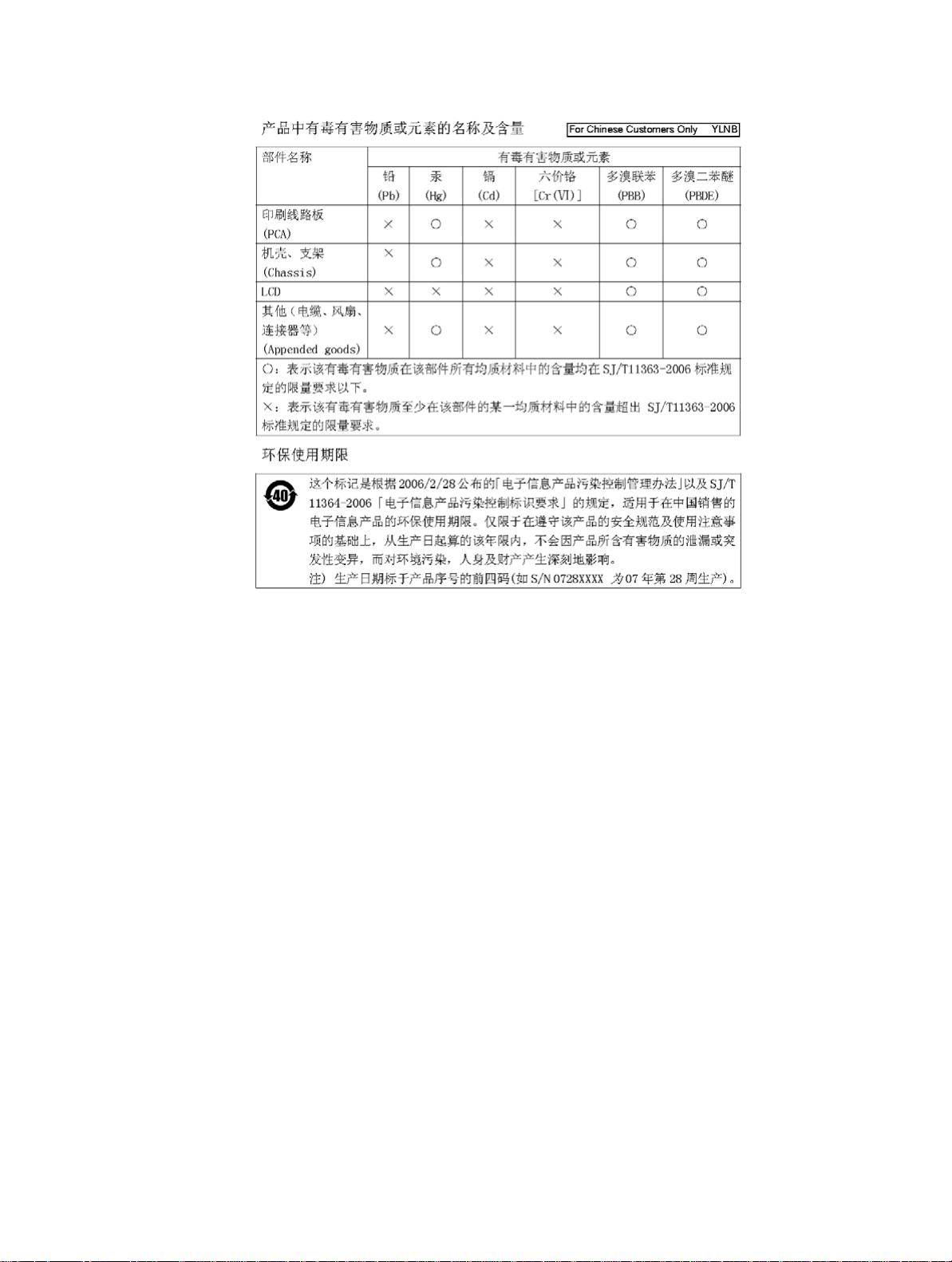
Mercury Notification
This product uses an LCD backlight lamp that contains mercury. Disposal may be regulated due to
environmental considerations. Please contact your local authorities or, within the United States, the
Electronics Industries Alliance (www.eiae.org) for disposal or recycling information.
Page 5
Page 6

Page 7
Safety Symbols
To prevent the risk of personal injury or loss related to equipment malfunction, Anritsu Company uses the
following symbols to indicate safety-related information. For your own safety, please read the information
carefully before operating the equipment.
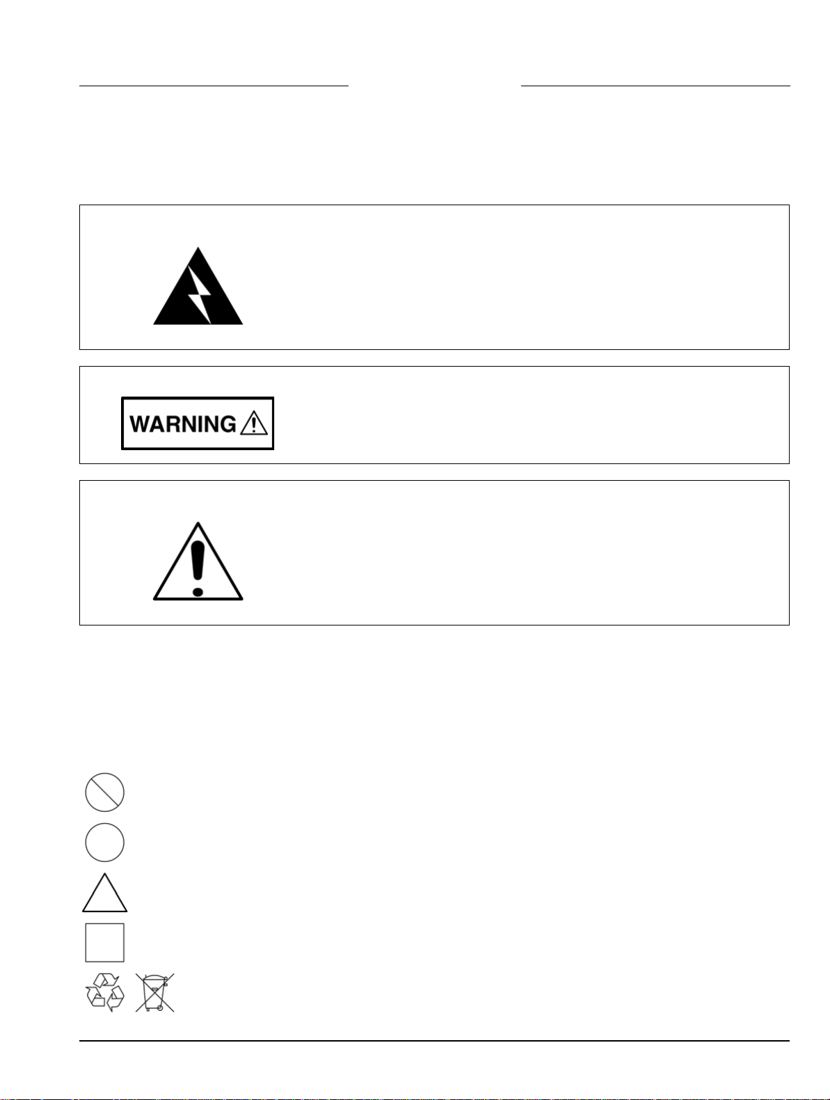
Symbols Used in Manuals
Danger
This indicates a very dangerous procedure that could result in serious
injury or death, and possible loss related to equipment malfunction, if not
performed properly.
Warning
This indicates a hazardous procedure that could result in light-to-severe
injury or loss related to equipment malfunction, if proper precautions are
not taken.
Caution
This indicates a hazardous procedure that could result in loss related to
equipment malfunction if proper precautions are not taken.
Safety Symbols Used on Equipment and in Manuals
The following safety symbols are used inside or on the equipment near operation locations to provide
information about safety items and operation precautions. Ensure that you clearly understand the meanings of
the symbols and take the necessary precautions before operating the equipment. Some or all of the following
five symbols may or may not be used on all Anritsu equipment. In addition, there may be other labels attached
to products that are not shown in the diagrams in this manual.
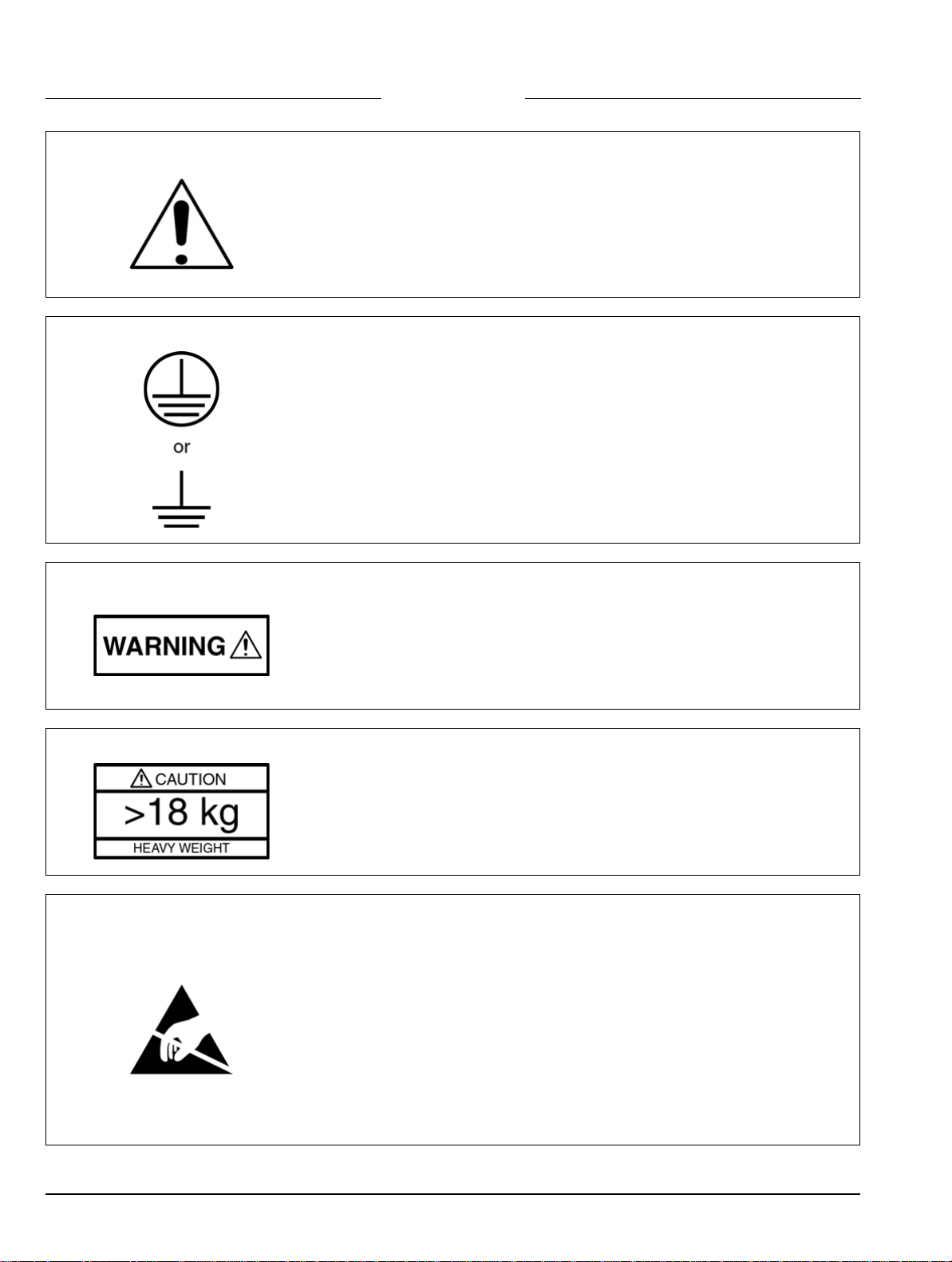
This indicates a prohibited operation. The prohibited operation is indicated symbolically in or near
the barred circle.
This indicates a compulsory safety precaution. The required operation is indicated symbolically in or
near the circle.
This indicates a warning or caution. The contents are indicated symbolically in or near the triangle.
This indicates a note. The contents are described in the box.
These indicate that the marked part should be recycled.
MS2711B Maintenance 10580-00072 C Safety-1
Page 8
For Safety
Warning
Warning
Warning
Always refer to the operation manual when working near locations at which
the alert mark, shown on the left, is attached. If the operation, etc., is
performed without heeding the advice in the operation manual, there is a
risk of personal injury. In addition, the equipment performance may be
reduced.
Moreover, this alert mark is sometimes used with other marks and
descriptions indicating other dangers.
When supplying power to this equipment, connect the accessory 3-pin
power cord to a 3-pin grounded power outlet. If a grounded 3-pin outlet is
not available, use a conversion adapter and ground the green wire, or
connect the frame ground on the rear panel of the equipment to ground. If
power is supplied without grounding the equipment, there is a risk of
receiving a severe or fatal electric shock.
This equipment can not be repaired by the operator. Do not attempt to
remove the equipment covers or to disassemble internal components.
Only qualified service technicians with a knowledge of electrical fire and
shock hazards should service this equipment. There are hig h-voltage p arts
in this equipment presenting a risk of severe injury or fatal electric shock to
untrained personnel. In addition, there is a risk of damage to precision
components.
Warning
Use two or more people to lift and move this equipment, or use an
equipment cart. There is a risk of back injury if this equipment is lifted by
one person.
Electrostatic Discharge (ESD) can damage the highly sensitive circuits in
the instrument. ESD is most likely to occur as test devices are being
Caution
Safety-2 10580-00072 C MS2711B Maintenance
connected to, or disconnected from, the instrument’s front and rear panel
ports and connectors. You can protect the instrument and test devices by
wearing a static-discharge wristband. Alternatively, you can ground
yourself to discharge any static charge by touching the outer chassis of the
grounded instrument before touching the instrume nt’s front and rear panel
ports and connectors. Avoid touching the test port center conductors
unless you are properly grounded and have eliminated the possibility of
static discharge.
Repair of damage that is found to be caused by electrostatic discharge is
not covered under warranty.
Page 9

Table of Contents
Chapter 1—General Information
1-1 Introduction. . . . . . . . . . . . . . . . . . . . . . . . . . . . . . . . . . . . . . . . . . . . . . . . . . . . . . . . . . . . . . . . 1-1
1-2 Identification Number . . . . . . . . . . . . . . . . . . . . . . . . . . . . . . . . . . . . . . . . . . . . . . . . . . . . . . . . 1-1
1-3 Description . . . . . . . . . . . . . . . . . . . . . . . . . . . . . . . . . . . . . . . . . . . . . . . . . . . . . . . . . . . . . . . . 1-1
1-4 Options . . . . . . . . . . . . . . . . . . . . . . . . . . . . . . . . . . . . . . . . . . . . . . . . . . . . . . . . . . . . . . . . . . . 1-1
1-5 Replaceable Parts . . . . . . . . . . . . . . . . . . . . . . . . . . . . . . . . . . . . . . . . . . . . . . . . . . . . . . . . . . 1-2
Chapter 2—Performance Verification
2-1 Performance Verification Procedures. . . . . . . . . . . . . . . . . . . . . . . . . . . . . . . . . . . . . . . . . . . . 2-1
2-2 Frequency Accuracy. . . . . . . . . . . . . . . . . . . . . . . . . . . . . . . . . . . . . . . . . . . . . . . . . . . . . . . . . 2-1
Equipment Required:. . . . . . . . . . . . . . . . . . . . . . . . . . . . . . . . . . . . . . . . . . . . . . . . . . . . . . 2-1
Procedure:. . . . . . . . . . . . . . . . . . . . . . . . . . . . . . . . . . . . . . . . . . . . . . . . . . . . . . . . . . . . . . 2-1
2-3 Phase Noise Verification. . . . . . . . . . . . . . . . . . . . . . . . . . . . . . . . . . . . . . . . . . . . . . . . . . . . . . 2-2
Equipment Required:. . . . . . . . . . . . . . . . . . . . . . . . . . . . . . . . . . . . . . . . . . . . . . . . . . . . . . 2-2
Procedure:. . . . . . . . . . . . . . . . . . . . . . . . . . . . . . . . . . . . . . . . . . . . . . . . . . . . . . . . . . . . . . 2-2
2-4 Second Harmonic Distortion Test. . . . . . . . . . . . . . . . . . . . . . . . . . . . . . . . . . . . . . . . . . . . . . . 2-4
Equipment Required:. . . . . . . . . . . . . . . . . . . . . . . . . . . . . . . . . . . . . . . . . . . . . . . . . . . . . . 2-4
Procedure:. . . . . . . . . . . . . . . . . . . . . . . . . . . . . . . . . . . . . . . . . . . . . . . . . . . . . . . . . . . . . . 2-4
2-5 Residual Spurious Response Test . . . . . . . . . . . . . . . . . . . . . . . . . . . . . . . . . . . . . . . . . . . . . . 2-6
Equipment Required:. . . . . . . . . . . . . . . . . . . . . . . . . . . . . . . . . . . . . . . . . . . . . . . . . . . . . . 2-6
Procedure:. . . . . . . . . . . . . . . . . . . . . . . . . . . . . . . . . . . . . . . . . . . . . . . . . . . . . . . . . . . . . . 2-6
2-6 Level Accuracy Test . . . . . . . . . . . . . . . . . . . . . . . . . . . . . . . . . . . . . . . . . . . . . . . . . . . . . . . . . 2-8
Equipment Required:. . . . . . . . . . . . . . . . . . . . . . . . . . . . . . . . . . . . . . . . . . . . . . . . . . . . . . 2-8
Procedure:. . . . . . . . . . . . . . . . . . . . . . . . . . . . . . . . . . . . . . . . . . . . . . . . . . . . . . . . . . . . . . 2-8
2-7 Dynamic Range Test . . . . . . . . . . . . . . . . . . . . . . . . . . . . . . . . . . . . . . . . . . . . . . . . . . . . . . . 2-10
Equipment required: . . . . . . . . . . . . . . . . . . . . . . . . . . . . . . . . . . . . . . . . . . . . . . . . . . . . . 2-10
Procedure:. . . . . . . . . . . . . . . . . . . . . . . . . . . . . . . . . . . . . . . . . . . . . . . . . . . . . . . . . . . . . 2-10
2-8 Power Monitor (Option 5) Verification. . . . . . . . . . . . . . . . . . . . . . . . . . . . . . . . . . . . . . . . . . . 2-11
Equipment Required:. . . . . . . . . . . . . . . . . . . . . . . . . . . . . . . . . . . . . . . . . . . . . . . . . . . . . 2-11
Procedure . . . . . . . . . . . . . . . . . . . . . . . . . . . . . . . . . . . . . . . . . . . . . . . . . . . . . . . . . . . . . 2-11
2-9 Preamplifier (Option 8) Verification. . . . . . . . . . . . . . . . . . . . . . . . . . . . . . . . . . . . . . . . . . . . . 2-12
Equipment Required:. . . . . . . . . . . . . . . . . . . . . . . . . . . . . . . . . . . . . . . . . . . . . . . . . . . . . 2-12
Procedure:. . . . . . . . . . . . . . . . . . . . . . . . . . . . . . . . . . . . . . . . . . . . . . . . . . . . . . . . . . . . . 2-12
2-10 Level Accuracy Test . . . . . . . . . . . . . . . . . . . . . . . . . . . . . . . . . . . . . . . . . . . . . . . . . . . . . . . . 2-14
Equipment Required:. . . . . . . . . . . . . . . . . . . . . . . . . . . . . . . . . . . . . . . . . . . . . . . . . . . . . 2-14
Procedure:. . . . . . . . . . . . . . . . . . . . . . . . . . . . . . . . . . . . . . . . . . . . . . . . . . . . . . . . . . . . . 2-14
MS2711B Maintenance 10580-00072 C Contents-1
Page 10

2-11 Tracking Generator (Option 20) Verification . . . . . . . . . . . . . . . . . . . . . . . . . . . . . . . . . . . . . . 2-17
Equipment Required:. . . . . . . . . . . . . . . . . . . . . . . . . . . . . . . . . . . . . . . . . . . . . . . . . . . . . 2-17
Procedure:. . . . . . . . . . . . . . . . . . . . . . . . . . . . . . . . . . . . . . . . . . . . . . . . . . . . . . . . . . . . . 2-17
Equipment Required:. . . . . . . . . . . . . . . . . . . . . . . . . . . . . . . . . . . . . . . . . . . . . . . . . . . . . 2-19
Procedure:. . . . . . . . . . . . . . . . . . . . . . . . . . . . . . . . . . . . . . . . . . . . . . . . . . . . . . . . . . . . . 2-19
Equipment Required:. . . . . . . . . . . . . . . . . . . . . . . . . . . . . . . . . . . . . . . . . . . . . . . . . . . . . 2-21
Procedure:. . . . . . . . . . . . . . . . . . . . . . . . . . . . . . . . . . . . . . . . . . . . . . . . . . . . . . . . . . . . . 2-21
Chapter 3—Removal and Replacement
3-1 Introduction. . . . . . . . . . . . . . . . . . . . . . . . . . . . . . . . . . . . . . . . . . . . . . . . . . . . . . . . . . . . . . . . 3-1
3-2 Static Sensitive Assembly Handling . . . . . . . . . . . . . . . . . . . . . . . . . . . . . . . . . . . . . . . . . . . . . 3-1
Additional Precautions. . . . . . . . . . . . . . . . . . . . . . . . . . . . . . . . . . . . . . . . . . . . . . . . . . . . . 3-2
3-3 Battery Pack Removal And Replacement. . . . . . . . . . . . . . . . . . . . . . . . . . . . . . . . . . . . . . . . . 3-3
Battery Testing Procedure. . . . . . . . . . . . . . . . . . . . . . . . . . . . . . . . . . . . . . . . . . . . . . . . . . 3-5
3-4 Front Panel Assembly Removal And Replacement . . . . . . . . . . . . . . . . . . . . . . . . . . . . . . . . . 3-6
3-5 LCD Assembly Replacement . . . . . . . . . . . . . . . . . . . . . . . . . . . . . . . . . . . . . . . . . . . . . . . . . . 3-8
3-6 Key Pad PCB Replacement . . . . . . . . . . . . . . . . . . . . . . . . . . . . . . . . . . . . . . . . . . . . . . . . . . . 3-9
3-7 Key Pad Membrane Replacement . . . . . . . . . . . . . . . . . . . . . . . . . . . . . . . . . . . . . . . . . . . . . 3-10
3-8 PCB Assembly Replacement . . . . . . . . . . . . . . . . . . . . . . . . . . . . . . . . . . . . . . . . . . . . . . . . . 3-11
Appendix A—Test Records
A-1 Preamplifier (Option 8) Level Accuracy Test Settings . . . . . . . . . . . . . . . . . . . . . . . . . . . . . . . A-2
A-2 Preamplifier (Option 8) Level Accuracy Test Characterization . . . . . . . . . . . . . . . . . . . . . . . . A-3
A-3 Preamplifier (Option 8) Level Accuracy Test Results . . . . . . . . . . . . . . . . . . . . . . . . . . . . . . . A-4
A-4 Tracking Generator Option Level Accuracy . . . . . . . . . . . . . . . . . . . . . . . . . . . . . . . . . . . . . . . A-5
A-5 Tracking Generator Harmonics and Spurious Test . . . . . . . . . . . . . . . . . . . . . . . . . . . . . . . . . A-5
Contents-2 10580-00072 C MS2711B Maintenance
Page 11

Chapter 1 — General Information
1-1 Introduction
This manual provides maintenance instructions for the MS2711B Spectrum Analyzer. It describes the product
and provides performance verification procedures, parts replacement procedures, and a replaceable parts list.
1-2 Identification Number
All Anritsu instruments are assigned a six-digit serial number, such as “101001”. This number appears on a
decal affixed to the back panel of the instrument. Please use this identification number during any
correspondence with Anritsu Service Centers about this instrument.
1-3 Description
The MS2711B Spectrum Analyzer is a synthesizer-based hand held spectrum analyzer that provides quick and
accurate signal results. Measurements can be easily made using the main instrument functions: frequency,
span, amplitude, and bandwidth. A simplified block diagram is provided in Figure 1-1.
Figure 1-1. MS2711B Spectrum Analyzer Block Diagram
1-4 Options
The following options are available for the MS2711B:
• Option 5: RF Wattmeter Power Monitor (RF detector not included)
• Option 8: 3/4 Built-in 20 dB Preamplifier, 1 MHz to 3 GHz
• Option 20: 3/4 Built-in Tracking Generator, 10 MHz to 3 GHz
Note
MS2711B Maintenance 10580-00072 C 1-1
Option 5 and Option 8 are mutually exclusive; that is, they cannot both be installed in the same
instrument at the same time.
Page 12

Replaceable Parts General Information
1-5 Replaceable Parts
Replaceable parts for the Model MS2711B Spectrum Analyzer are listed below.
Table 1-1. Replaceable Parts List
Part Number Description Qty
Accessories
10580-00074
10580-00071
2300-347
40-115
2000-1029
806-62
800-441
48258
510-87
551-152
15-102
633-27
ND58427
ND58428
User Guide, MS2711B Spectrum Analyzer 1
Programming Manual, MS2711B Spectrum Analyzer (available on disk only) 1
Software Tools, MS2711B Spectrum Analyzer 1
Power Supply 1
Battery Charger 1
Cable Assy, Cig Plug, Female 1
Serial Interface Cable Assy 1
Soft Carrying Case 1
Replaceable Parts
N-Connector 1
Option 05 Input Connector 1
Liquid Crystal Display Assy 1
Rechargeable Battery, NiMH 1
MS2711B PCB Assembly 1
MS2711B PCB Assembly with Option 05 1
ND58429
ND58430
ND58431
ND58432
52737-3
46649-3
ND56502
900-861
900-869
900-720
900-697
900-326
MS2711B PCB Assembly with Option 8 1
MS2711B PCB Assembly with Option 20 1
MS2711B PCB Assembly with Option 05 and Option 20 1
MS2711B PCB Assembly with Option 08 and Option 20 1
Keypad PCB Assy 1
Membrane Keypad, Main 1
Speaker and Cable Assembly 1
Hardware
Pan Head Screw, 4-20, 0.365 18
Screw, 4-40, 0.875 4
Screw, 4-40, 0.187 9
Screw, 4-40, 0.312 3
Kep Nut, 4-40, 0.187 12
1-2 10580-00072 C MS2711B Maintenance
Page 13

General Information Replaceable Parts
Table 1-1. Replaceable Parts List (Continued)
Part Number Description Qty
Hardware (Continued)
790-516
790-42
761-79
46652-4
46653-1
48231-1
790-509
790-510
790-511
46655
46662
48241
48278
46659
46661
Hole Plug, 0.6875L 1
Hole Plug, 0.625 1
Cap Vinyl, Black, round 1
Case Parts
Top Case 1
Bottom Case 1
Battery Door 1
1
Battery Door Latch (3 pieces)
Case Corner Bumpers 4
LCD Retainer Plate 1
Foam, LCD Corners 8
Foam, LCD Window 1
Foam, LCD Backing 1
Foam, Keypad Backing 1
48246
48271
720-19
790-515
55212
Foam, Battery Door 1
Foam, Battery Compartment 1
Cable Clamp 1
Spring, Battery Compartment 3
ID Label, Model MS2711B 1
MS2711B Maintenance 10580-00072 C 1-3
Page 14

Replaceable Parts General Information
1-4 10580-00072 C MS2711B Maintenance
Page 15

Chapter 2 — Performance Verification
2-1 Performance Verification Procedures
The following procedures can be used to verify the performance of the MS2711B Spectrum Analyzer having
firmware version 2.09 or later.
2-2 Frequency Accuracy
The following test can be used to verify the CW frequency accuracy of the Spectrum Analyzer.
Equipment Required:
• Anritsu MG3692A Synthesized Signal Source with Option 15A, or equivalent
• Anritsu 34RSN50 50 ohm adapter or equivalent
• Anritsu 15NNF50-1.5C RF Coaxial Cable or equivalent
• 10 MHz Reference Standard
• BNC male to BNC male coaxial cable
Procedure:
1. Connect the 10 MHz reference source to the Anritsu MG3692A Synthesized Signal Source.
2. Connect the output of the source to the MS2711B RF Input.
3. Connect the external power supply (Anritsu part number 40-115) to the MS2711B.
4. Press and hold the ESCAPE/CLEAR key, then press the ON/OFF key to turn on the Spectrum Analyzer.
(This sets the instrument to the factory preset state.)
5. Turn on the 10 MHz reference source and the Anritsu MG3692A Synthesized Signal Source.
6. Set the MG3692A output to 2000 MHz CW with an RF output level of 0 dBm.
Note Before continuing, allow a 30-minute warm up for the internal circuitry to stabilize.
7. On the MS2711B, press the AMPLITUDE key and the REF LEVEL soft key.
8. Enter 20 and press the ENTER key to set the Reference Level to 20 dBm.
9. Press the FREQ/SPAN key and the CENTER soft key.
10. Enter 2000 and press the ENTER key to set the center frequency to 2000 MHz.
11. Press the SPAN soft key and enter 50. Press the kHz soft key to set the span to 50 kHz.
12. Press the BW/SWEEP key.
13. Press the RBW soft key and then the MANUAL soft key. Use the Up/Down arrow key to select 10 kHz.
Press ENTER to set the resolution bandwidth to 10 kHz, and press BACK.
14. Press the VBW soft key and then the MANUAL soft key. Use the Up/Down arrow key to select 3 kHz.
Press ENTER to set the video bandwidth to 3 kHz.
15. Press the MARKER (8) key, then the M1 soft key.
16. Press the EDIT soft key and use the Up/Down arrow key to center the marker on the waveform. Verify
that the marker frequency is 2000 MHz ±4 kHz.
MS2711B Maintenance 10580-00072 C 2-1
Page 16

Phase Noise Verification Performance Verification
2-3 Phase Noise Ve rification
Equipment Required:
• Anritsu MG3692A Synthesized Signal Source with Option 2A, Option 4, and Option 15A, or equivalent
• Anritsu 34RSN50 50 ohm adapter or equivalent
• Anritsu 15NNF50-1.5C RF Coaxial Cable or equivalent
Procedure:
1. Connect the output of the source to the MS2711B RF Input.
2. Connect the external power supply (Anritsu part number 40-115) to the MS2711B.
3. Press and hold the ESCAPE/CLEAR key, then press the ON/OFF key to turn on the Spectrum Analyzer.
(This sets the instrument to the factory preset state.)
Note Before continuing, allow a 30-minute warm up for the internal circuitry to stabilize.
4. Set the MG3692A output to 1000 MHz CW with an RF output level of – 30 dBm.
5. On the MS2711B, press the BW/SWEEP key.
6. Press the RBW soft key and then the MANUAL soft key. Use the Up/Down arrow key to select 10 kHz.
Press ENTER to set the resolution bandwidth to 10 kHz, and then press BACK.
7. Press the VBW soft key and then the MANUAL soft key. Use the Up/Down arrow key to select 3 kHz.
Press ENTER to set the video bandwidth to 3 kHz.
8. On the MS2711B, press the FREQ/SPAN key and the CENTER soft key.
9. Enter 1000 and press the MHz soft key to set the center frequency to 1000 MHz.
10. Press the SPAN soft key and enter 0.1. Press the MHz soft key to set the span to 0.100 MHz.
11. Press the AMPLITUDE key.
12. Press the REF LEVEL soft key and enter –27. Press the ENTER key to set the reference level to – 27 dBm.
13. Press the MARKER (8) key, then the M1 soft key.
14. Press EDIT and enter 1000. Press the MHz soft key to set the M1 marker frequency to 1000 MHz.
15. Press the BACK soft key and the M2 soft key.
16. Press EDIT and enter 1000.03. Press MHz to set the M2 marker frequency to 1000.030 MHz (30 kHz
higher than the center frequency).
17. Press the DELTA (M2-M1)
18. Press the SINGLE/CONT (+/–) key and read and record the D2 reading.
19. Press the SINGLE/CONT (+/–) key to read and record five values, then calculate the average of the five
recorded values.
20. Subtract 40 dB from the average value and verify that the result is ≤ –75 dBc/Hz.
(For example: –35dBc measured –40dB=–75dBc/Hz.)
soft key.
2-2 10580-00072 C MS2711B Maintenance
Page 17

Performance Verification Phase Noise Verification
The measured value is converted to dBc/Hz using the following formula:
dBc
---------- -
Hz
Note
At 10 kHz RBW, , so
dBc
---------- -
Hz
21. Press the BACK soft key and the M3 soft key.
22. Press the EDIT key and enter 999.970. Press MHz to set the M3 marker frequency to 999.970 MHz
(30 kHz lower than the center frequency).
23. Press the DELTA (M3-M1) soft key.
24. Press the SINGLE/CONT (+/–) key. Read and record the Δ3 reading.
25. Press the SINGLE/CONT (+/–) key to read and record five values, then calculate the average of the five
recorded values.
Subtract 40 dB from the average value and verify that the result is ≤ –75 dBc/Hz.
(For example: –35 dBc measured –40 dB = –75 dBc/Hz)
measured dBc⋅ 10
RBW
⎛⎞
10
--------------
⎝⎠
1Hz
measured dBc⋅–40–=
40=log×
RBW
⎛⎞
--------------
log×––=
⎝⎠
1Hz
MS2711B Maintenance 10580-00072 C 2-3
Page 18

Second Harmonic Distortion Test Performance Verification
2-4 Second Harmonic Distortion Test
The following test can be used to verify the input related spurious response of the Spectrum Analyzer.
Equipment Required:
• Anritsu MG3692A Synthesized Signal Source with Option 2A, Option 4, and Option 15A, or equivalent
• Anritsu 34RSN50 50 ohm adapter or equivalent
• Anritsu 15NNF50-1.5C RF Coaxial Cable or equivalent
• 10 MHz Reference Standard
• 50 MHz Low Pass Filter (Anritsu part number 1030-96)
• BNC male to BNC male coaxial cable
Procedure:
1. Connect the 10 MHz reference source to the Anritsu MG3692A Synthesized Signal Source.
2. Connect one end of the 50 MHz Low Pass Filter to the output of the source and the other end to the
Spectrum Analyzer RF Input with the RF coaxial cable.
3. Connect the external power supply (Anritsu part number 40-115) to the Site Master.
4. On the MS2711B, press and hold the ESCAPE/CLEAR key, then press the ON/OFF key to turn on the
Spectrum Analyzer. (This sets the instrument to the factory preset state.)
5. Turn on the 10 MHz reference source and the Anritsu MG3692A Synthesized Signal Source.
6. Set the MG3692A output to 40 MHz CW, with an RF output level of –30 dBm.
Note Before continuing, allow a 30-minute warm up for the internal circuitry to stabilize.
7. On the Spectrum Analyzer, press the AMPLITUDE key and the REF LEVEL soft key.
8. Enter –27 and press the ENTER key to set the Reference Level to –27 dBm.
9. Press the SCALE soft key and enter 7, then press ENTER.
10. Press the FREQ/SPAN key and then the CENTER soft key.
11. Enter 40 and press the MHz soft key to set the center frequency to 40 MHz.
12. Press the SPAN soft key and enter 0.2. Press the MHz soft key to set the span to 0.200 MHz.
13. Press the BW/SWEEP key.
14. Press the RBW soft key and then the MANUAL soft key. Use the Up/Down arrow key to select 10 kHz.
Press ENTER to set the resolution bandwidth to 10 kHz and press BACK.
15. Press the VBW soft key and then the MANUAL soft key. Use the Up/Down arrow key to select 3 kHz.
Press ENTER to set the video bandwidth to 3 kHz.
16. Press the MARKER (8) key, then the M1 soft key.
17. Press the EDIT soft key, then enter 40. Press the MHz soft key to set M1 to 40 MHz.
18. On the MG3692A Synthesized Signal Source, adjust the output level so that the M1 reading of the
Spectrum Analyzer is –30 dBm at 40 MHz.
19. On the Spectrum Analyzer, press the FREQ/SPAN key and then the CENTER soft key.
20. Enter 80 and press the MHz soft key to set the center frequency to 80 MHz.
21. Press the MARKER (8) key and the M1 soft key.
22. Press the EDIT soft key, then enter 80. Press the MHz soft key to set M1 to 80 MHz.
23. Record the amplitude of the signal at M1 80 MHz:
Second Harmonic Level @ 80 MHz =____dBm
2-4 10580-00072 C MS2711B Maintenance
Page 19

Performance Verification Second Harmonic Distortion Test
24. Convert this measured value to dBc using the following formula:
Input Related Spurious Response (dBc) =
[Second Harmonic Level @ 80 MHz] + 30 dBm = ___ dBc
Specifications for this measurement are –45 dBc with –30 dBm into the first
mixer.
MS2711B Maintenance 10580-00072 C 2-5
Page 20

Residual Spurious Response Test Performance Verification
2-5 Residual Spurious Response Test
The following test can be used to verify the residual spurious response of the Spectrum Analyzer.
Equipment Required:
Anritsu 28N50-2 or SM/PL 50 ohm Termination or equivalent
Procedure:
1. Connect the 50 ohm termination to the Spectrum Analyzer RF Input.
2. On the Spectrum Analyzer, press and hold the ESCAPE/CLEAR key, then press the ON/OFF key to turn
on the Spectrum Analyzer. (This sets the instrument to the factory preset state.)
Note Before continuing, allow a 30-minute warm up for the internal circuitry to stabilize.
3. On the Spectrum Analyzer, press the AMPLITUDE key and the REF LEVEL soft key.
4. Enter –75 and press the ENTER key to set the Reference Level to –75 dBm.
5. Press the SCALE soft key and enter 5, then press ENTER.
6. Press the BW/SWEEP key.
7. Press the RBW soft key and then the MANUAL soft key. Use the Up/Down arrow key to select 10 kHz.
Press ENTER to set the resolution bandwidth to 10 kHz, and press BACK.
8. Press the VBW soft key and then the MANUAL soft key. Use the Up/Down arrow key to select 100 Hz, and
press ENTER to set the video bandwidth to 100 Hz.
9. Press the FREQ/SPAN key and the START soft key.
10. Enter 500 and press the kHz soft key to set the start frequency to 500 kHz.
11. Press the STOP soft key and enter 4, then press the MHz soft key to set the stop frequency to 4 MHz.
12. Wait until one full sweep is complete.
13. Press the MARKER (8) key and then the M1 soft key.
14. Press the ON/OFF soft key and then the MARKER TO PEAK soft key.
15. Record the M1 amplitude reading and verify whether it is less than or equal to –90 dBm.
If a spur with an amplitude larger than –90 dBm occurs, then wait another full sweep and observe
Note
16. Press the BW/SWEEP key.
17. Press the VBW soft key and then the MANUAL soft key. Use the Up/Down arrow key to select 3 kHz, and
press ENTER
18. Press the FREQ/SPAN key and the START soft key.
19. Enter 4 and press the MHz soft key to set the start frequency to 4 MHz.
20. Press the STOP soft key and enter 1000, then press the MHz soft key to set the stop frequency
to 1000 MHz.
21. Wait until one full sweep is complete.
whether the spur occurs at the same point on the second sweep. If the spur does not occur at the
same point on the second sweep, then the spur on the first sweep was not real.
to set the video bandwidth to 3 kHz.
22. Press the MARKER (8) key and then the M1 soft key.
23. Press the ON/OFF soft key and then the MARKER TO PEAK soft key.
24. Record the M1 amplitude reading and verify that it is ≤ –90 dBm.
25. Press the FREQ/SPAN key and the START soft key.
2-6 10580-00072 C MS2711B Maintenance
Page 21

Performance Verification Residual Spurious Response Test
26. Enter 1000 and press the MHz soft key to set the start frequency to 1000 MHz.
27. Press the STOP soft key and enter 2000, then press MHz soft key to set the stop frequency to 2000 MHz.
28. Wait until one full sweep is complete.
29. Press the MARKER (8) key and then the M1 soft key.
30. Press the ON/OFF soft key and then the MARKER TO PEAK soft key.
31. Record the M1 amplitude reading and verify that it is ≤ –90 dBm.
32. Press the FREQ/SPAN key and the START soft key.
33. Enter 2000 and press the MHz soft key to set the start frequency to 2000 MHz.
34. Press the STOP soft key and enter 3000, then press the MHz soft key to set the stop frequency
to 3000 MHz.
35. Wait until one full sweep is complete.
36. Press the MARKER (8) key and then the M1 soft key.
37. Press the ON/OFF soft key and then the MARKER TO PEAK soft key.
38. Record the M1 amplitude reading and verify that it is ≤ –90 dBm.
MS2711B Maintenance 10580-00072 C 2-7
Page 22
Level Accuracy Test Performance Verification
2-6 Level Accuracy Test
This test verifies the level accuracy of the Spectrum Analyzer.
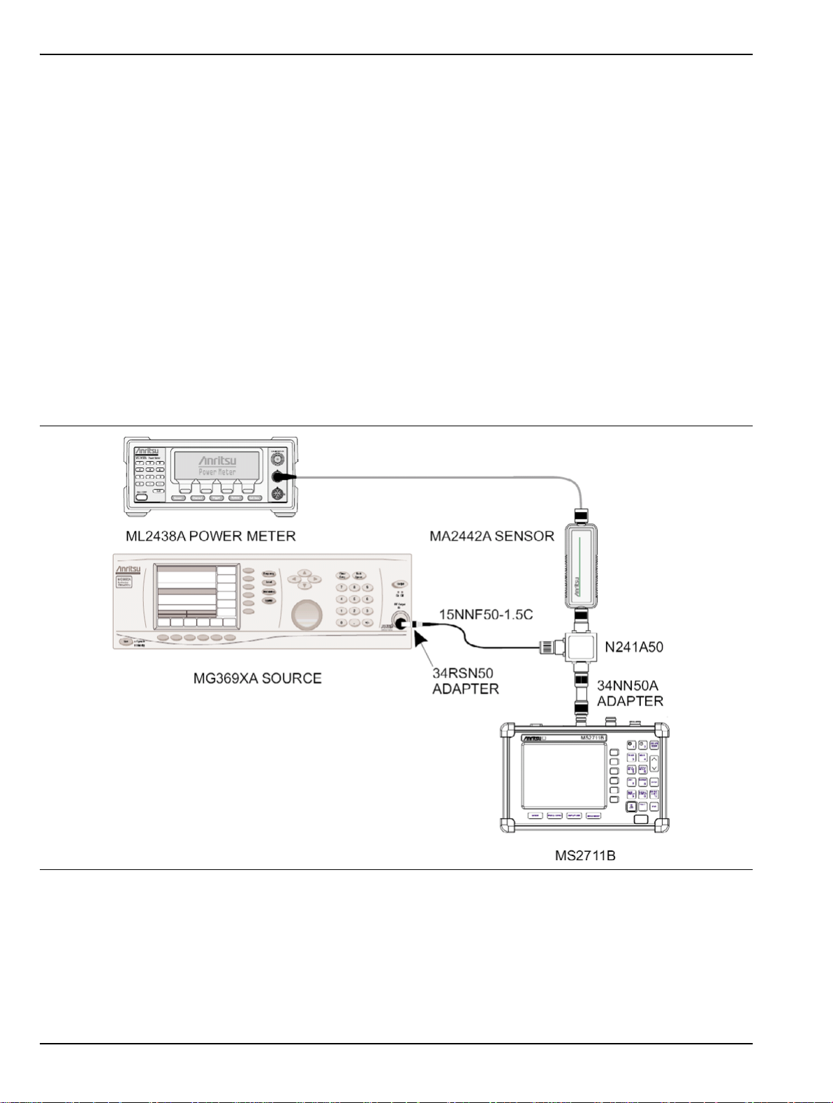
Equipment Required:
Anritsu MG3692A Synthesized Signal Source, with Option 2A, Option 4, and Option 15A
Anritsu ML2430A-Series Power Meter or equivalent
Anritsu MA2442A High Accuracy Power Sensor or equivalent
Anritsu N241A50 Power Splitter or equivalent
Anritsu 34NN50A 50 ohm adapter or equivalent
Anritsu 34RSN50 50 ohm adapter or equivalent
Anritsu 15NNF50-1.5C RF Coaxial Cable or equivalent
Procedure:
1. Connect the power sensor to the power meter and calibrate the sensor.
2. Using the power splitter, coaxial cable and adapters, connect the Spectrum Analyzer to the signal source
and the power sensor as shown in Figure 2-1
Figure 2-1. Measurement Accuracy Setup
3. Connect the external power supply (Anritsu part number 40-115) to the Spectrum Analyzer.
4. On the Spectrum Analyzer, press and hold the ESCAPE/CLEAR key, then press the ON/OFF key to turn
on the Spectrum Analyzer. (This sets the instrument to the factory preset state.)
2-8 10580-00072 C MS2711B Maintenance
Page 23

Performance Verification Level Accuracy Test
5. Turn on the power meter and signal source.
Note Before continuing, allow a 30-minute warm up for the internal circuitry to stabilize.
6. On the Spectrum Analyzer, press the BW/SWEEP key.
7. Press the RBW soft key and then the MANUAL soft key. Use the Up/Down arrow key to select 10 kHz.
Press ENTER to set the resolution bandwidth to 10 kHz.
8. Press BACK, then the VBW soft key, and then the MANUAL soft key. Use the Up/Down arrow key to
select 3 kHz. Press ENTER to set the video bandwidth to 3 kHz.
9. Press BACK, then DETECTION, then AVERAGE.
10. Press the FREQ/SPAN key.
11. Press the SPAN soft key and enter 0.5, then press the MHz key to set the span to 0.5 MHz.
12. Press the AMPLITUDE key.
13. Press the REF LEVEL soft key, enter –20, and press the ENTER key to set the reference level to –20 dBm.
14. Press the FREQ/SPAN key and the CENTER soft key.
15. Enter 50 and press the MHz soft key to set the center frequency to 50 MHz.
16. On the Anritsu ML2430A-Series Power Meter, press the Sensor key and then the CalFactor soft key.
Press the FREQ soft key and enter 50 MHz for the Input Signal Frequency. This sets the power meter to
the proper power sensor cal factor. Press the Sensor key to display the power reading.
17. Set the MG3692A power level to –30 dBm as indicated on the power meter.
18. Verify that the M1 reading is within ± 1 dBm maximum from the input signal.
MS2711B Maintenance 10580-00072 C 2-9
Page 24

Dynamic Range Test Performance Verification
2-7 Dynamic Range Test
This test can be used to verify the dynamic range of the Spectrum Analyzer.
Equipment required:
• Two Anritsu MG3692A Synthesized Signal Sources with Option 2A, Option 4, and Option 15A, or
equivalent
• Anritsu N241A50 Power Splitter or equivalent
• Anritsu 34NN50A 50 ohm adapter or equivalent
• Anritsu 34RSN50 50 ohm adapter or equivalent
• Two Anritsu 15NNF50-1.5C RF Coaxial Cables or equivalent
Procedure:
1. Connect the output of the Power Splitter to the RF In port of the Spectrum Analyzer.
2. Connect the output of both signal sources to the input of the Power Splitter and turn on both sources.
3. On the Spectrum Analyzer, press and hold the ESCAPE/CLEAR key, then press the ON/OFF key to turn
on the Spectrum Analyzer. (This sets the instrument to the factory preset state.)
Note Before continuing, allow a 30-minute warm up for the internal circuitry to stabilize.
4. Set the center frequency of the first source to 1.0 GHz, and set the center frequency of the second source
to 1.2 GHz.
5. On the Spectrum Analyzer, press the FREQ/SPAN key.
6. Press the CENTER soft key, enter 1100, and press the MHz soft key to set the center frequency
to 1100 MHz.
7. Press the SPAN soft key and enter 500, then press the MHz key to set the span to 500 MHz.
8. Press the AMPLITUDE key and then the REF LEVEL soft key.
9. Enter –20 and then press the ENTER key to set the reference level to –20 dBm.
10. Press the BW/SWEEP key.
11. Press the RBW soft key and then the MANUAL soft key. Use the Up/Down arrow key to select 30 kHz,
then press ENTER to set the resolution bandwidth to 30 kHz.
12. Press BACK, then the VBW soft key, and then the MANUAL soft key. Use the Up/Down arrow key to
select 30 kHz, then press ENTER to set the video bandwidth to 30 kHz.
13. Adjust the signal levels of both signal sources so that both signal peaks are at – 20 dBm as indicated on
the Spectrum Analyzer display.
14. Refer to Step 10 through Step 12, and set the RBW to 10 kHz and the VBW to 1 kHz.
15. When the sweep is complete, reduce the power level of the second source signal to below –85 dBm and
verify that the signal is visible at below –85 dBm.
2-10 10580-00072 C MS2711B Maintenance
Page 25
Performance Verification Power Monitor (Option 5) Verification
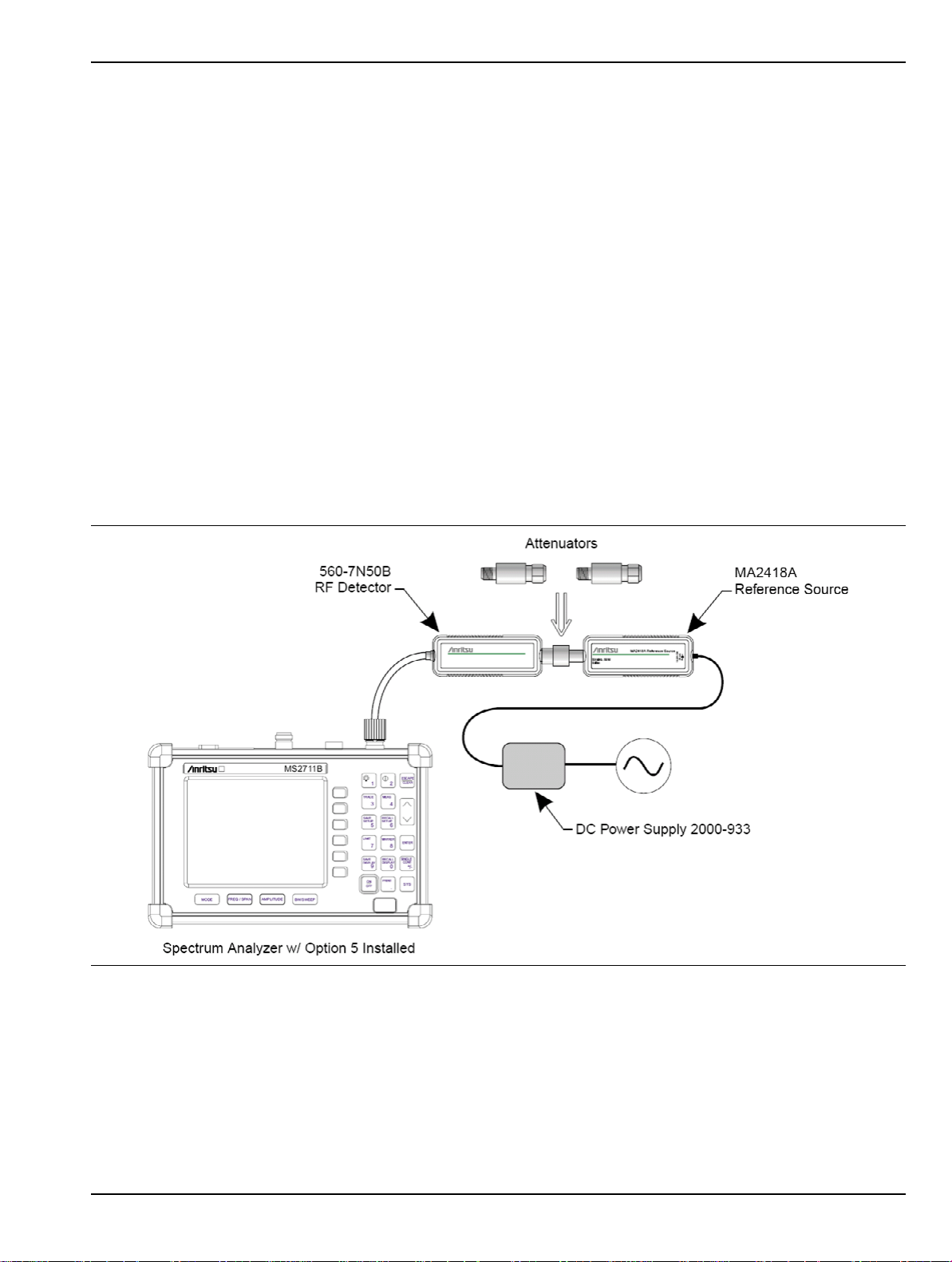
2-8 Power Monitor (Option 5) Verification
If the Power Monitor is installed in the Spectrum Analyzer, then the following test can be used to verify the
accuracy of the power measurements. Measurement calibration of the Spectrum Analyzer is not required for
this test.
Equipment Required:
RF Detector, 10 MHz to 20 GHz, Anritsu 560-7N50B
10 dB Attenuator, Weinschel 1-10
30 dB Attenuator, Weinschel 1-30
RF Reference Source, 0.050 GHz, Anritsu MA2418A
DC Power Supply, Anritsu 2000-933
Procedure
1. Connect the DC power supply to the MA2418A Reference Source. (Refer to Figure 2-2.)
2. Connect the MA2418A Reference Source to the input of the 560-7N50B RF detector.
3. Connect the RF Detector output to the RF Detector input of the MS2711B Spectrum Analyzer.
4. Connect the DC power supply to the appropriate line voltage in order to supply power to the MA2418A
Reference Source.
Figure 2-2. Power Monitor Verification
5. Press and hold the ESCAPE/CLEAR key, then press the ON/OFF key to turn on the Spectrum Analyzer.
(This sets the instrument to the factory preset state.)
6. Press the MODE soft key.
7. Use the Up/Down arrow key to highlight POWER MONITOR, then press ENTER.
8. Press the ZERO soft key to zero the power monitor. When complete, ZERO ADJ:ON is displayed in the
message area.
MS2711B Maintenance 10580-00072 C 2-11
Page 26

Preamplifier (Option 8) Verification Performance Verification
9. Verify that the power monitor reading is 0.0 dBm ±1 dB.
10. Connect the output of the MA2418A Reference Source to the two attenuators so as to add 40 dB of
attenuation (refer to Figure 2-2).
11. Connect the MA2418A Reference Source and the attenuators to the input of the 560-7N50B RF detector.
12. Verify that the power monitor reading is now –40.0 dBm ±2 dB.
2-9 Preamplifier (Option 8) Verification
If the Preamplifier (Option 8) is installed in the Spectrum Analyzer, then the following tests can be used to
verify the functionality of the Preamplifier.
Displayed Average Noise Level (DANL)
This test verifies the performance of the displayed average noise level with the Preamplifier turned on.
Equipment Required:
Anritsu 28N50-2 or SM/PL 50 ohm Termination or equivalent
Procedure:
1. Connect the 50 ohm termination to the MS2711B RF Input.
2. On the Spectrum Analyzer, press and hold the ESCAPE/CLEAR key, then press the ON/OFF key to turn
on the Spectrum Analyzer. (This sets the instrument to the factory preset state.)
Note Before continuing, allow a 30-minute warm up for the internal circuitry to stabilize.
3. On the MS2711B, press the AMPLITUDE key and the REF LEVEL soft key.
4. Enter –75 and press the ENTER key to set the Reference Level to –75 dBm.
5. Press the SCALE soft key and enter 5, then press ENTER.
6. Press the BW/SWEEP key.
7. Press the DETECTION soft key, then press the AVERAGE soft key, then press BACK.
8. Press the RBW soft key and then the MANUAL soft key. Use the Up/Down arrow key to select 10 kHz.
9. Press ENTER to set the resolution bandwidth to 10 kHz, and press the BACK soft key.
10. Press the VBW soft key and then the MANUAL soft key. Use the Up/Down arrow key to select 100 Hz.
Press ENTER to set the video bandwidth to 100 Hz.
11. Press the MEAS (4) key and then press the PREAMP soft key to turn the Preamplifier on.
12. Press the FREQ/SPAN key and the START soft key.
13. Enter 1 and press the MHz soft key to set the start frequency to 1 MHz.
14. Press the STOP soft key and enter 4, then press the MHz soft key to set the stop frequency to 4 MHz.
15. Wait until a full sweep is complete.
16. Press the MARKER (8) key and then press the M1 soft key.
17. Press the MARKER TO PEAK soft key. Record the M1 amplitude reading and verify that it is ≤ –115 dBm.
18. Press the BW/SWEEP key.
19. Press the VBW soft key, and then the MANUAL soft key. Use the Up/Down arrow key to select 3 kHz.
Press ENTER to set the video bandwidth to 3 kHz.
20. Press the FREQ/SPAN key and the START soft key.
21. Enter 4 and press the MHz soft key to set the start frequency to 4 MHz.
2-12 10580-00072 C MS2711B Maintenance
Page 27

Performance Verification Preamplifier (Option 8) Verification
22. Press the STOP soft key and enter 1000, then press the MHz soft key to set the stop frequency
to 1000 MHz.
23. Wait until a full sweep is complete.
24. Press the MARKER (8) key and then press the M1 soft key.
25. Press the MARKER TO PEAK soft key. Record the M1 amplitude reading and verify that it is ≤ – 115 dBm.
26. Press the FREQ/SPAN key and the START soft key.
27. Enter 1000 and press the MHz soft key to set the start frequency to 1000 MHz.
28. Press the STOP soft key, enter 2000, and press the MHz soft key to set the stop frequency to 2000 MHz.
29. Wait until a full sweep is complete.
30. Press the MARKER (8) key and then press the M1 soft key.
31. Press the MARKER TO PEAK soft key. Record the M1 amplitude reading and verify that it is ≤ – 115 dBm.
32. Press the FREQ/SPAN key and the START soft key.
33. Enter 2000 and press the MHz soft key to set the start frequency to 2000 MHz.
34. Press the STOP soft key and enter 3000, then press MHz soft key to set the stop frequency to 3000 MHz.
35. Wait until a full sweep is complete.
36. Press the MARKER (8) key and then press the M1 soft key.
37. Press the MARKER TO PEAK soft key. Record the M1 amplitude reading and verify whether it
is ≤ –115 dBm.
MS2711B Maintenance 10580-00072 C 2-13
Page 28

Level Accuracy Test Performance Verification
2-10 Level Accuracy Test
This test verifies the level accuracy of the spectrum analyzer with the Preamplifier turned on.
Equipment Required:
• Anritsu MG3692A Synthesized Signal Source, with Option 2A, Option 4, and Option 15A
• Anritsu ML2430A-Series Power Meter or equivalent
• Anritsu MA2442A High Accuracy Power Sensor or equivalent
• Anritsu N241A50 Power Splitter or equivalent
• Anritsu 34NN50A 50 ohm adapter or equivalent
• Anritsu 34RSN50 50 ohm adapter or equivalent
• Anritsu 34RKNF50 50 ohm adapter or equivalent
• Anritsu 15NNF50-1.5C RF Coaxial Cable or equivalent
• Weinschel 1-30 Fixed Attenuator, 30 dB
Procedure:
1. Connect the power sensor to the power meter and calibrate the sensor.
2. Connect the power meter, source, sensor, and attenuator as shown in Figure 2-3.
Figure 2-3. Power Meter Setup
3. On the power meter, press the Sensor key, the Cal Factor soft key, and then the FREQ soft key. Use the
keypad to enter 50 MHz as the input signal frequency, which sets the power meter to the proper power
sensor cal factor.
4. Set the MG3692A output power level to 5 dBm.
5. Set the MG3692A output to 50 MHz CW.
6. Connect the power sensor to the RF output of the MG3692A. Record the output power level in Table A-1,
“Preamplifier Level Accuracy Test Settings” on page A-2 in Appendix A “Test Records”.
7. Connect the 30 dB Fixed Attenuator between the RF output of the MG3692A and the power sensor.
2-14 10580-00072 C MS2711B Maintenance
Page 29

Performance Verification Level Accuracy Test
8. Enter the proper input signal frequency into the power meter and record the measured value in
Table A-1.
9. Calculate the Attenuator Insertion Loss using the following formula:
Attenuator Loss = Output Power @ Source – Output Power @ Attenuator
10. Disconnect the 30 dB Fixed Attenuator.
11. Repeat Step 6 through Step 10 for frequencies of 500 MHz, 1000 MHz, 1500 MHz, 2000 MHz, 2500 MHz
and 2950 MHz.
12. Using the power splitter, coaxial cable, adapters, and fixed attenuator, connect the MS2711B to the
signal source and to the power sensor as shown in Figure 2-4.
Figure 2-4. Level Accuracy Setup
13. Calculate the output power level that is required at the power splitter end that is connected to the power
sensor in order to provide the desired power level at the MS2711B RF Input. Record the calculated value
in Table A-2, “Attenuator Characterization” on page A-3 in Appendix A “Test Records”.
14. Connect the external power supply (Anritsu part number 40-115) to the MS2711B.
15. On the Spectrum Analyzer, press and hold the ESCAPE/CLEAR key, then press the ON/OFF key to turn
on the Spectrum Analyzer. (This sets the instrument to the factory preset state.)
16. Turn on the power meter and signal source.
Note Before continuing, allow a 30-minute warm up for the internal circuitry to stabilize.
17. Press the BW/SWEEP key.
18. Press the RBW soft key and then the MANUAL soft key. Use the Up/Down arrow key to select 10 kHz.
Press ENTER to set the resolution bandwidth to 10 kHz.
19. Press BACK, then the VBW soft key and then the MANUAL soft key. Use the Up/Down arrow key to
select 3 kHz, then press ENTER to set the video bandwidth to 3 kHz.
20. Press BACK, then DETECTION, then AVERAGE, and then press BACK.
MS2711B Maintenance 10580-00072 C 2-15
Page 30

Level Accuracy Test Performance Verification
21. Press the MEAS (4) key and then press the PREAMP soft key to turn the Preamplifier on.
22. Press the FREQ/SPAN key.
23. Press the SPAN soft key and enter 0.5, then press the MHz key to set the span to 0.5 MHz.
24. Press the AMPLITUDE key.
25. Press the REF LEVEL soft key and enter – 40, and then press the ENTER key to set the reference level
to –40 dBm.
26. Press the FREQ/SPAN key and the CENTER soft key.
27. Enter 50 and press the MHz soft key to set the center frequency to 50 MHz.
28. On the power meter, press the Sensor key and then the CalFactor soft key. Press the FREQ soft key, then
use the keypad to enter 50 MHz for the Input signal Frequency. This sets up the power meter to use the
proper power sensor Cal Factor. Press the Sensor key to display the power reading.
29. Set the MG3692A output to 50 MHz CW and the power level to the value that was recorded in the
Required Power Meter Level column of Table A-2, “Attenuator Characterization” on page A-3 in
Appendix A “Test Records” for –50 dBm, as indicated on the power meter.
Note
30. On the MS2711B, press the MARKER (8) key, then the M1 soft key.
31. Press the MARKER TO PEAK soft key to position the marker at the center of the response for the test
frequency.
32. Verify that the M1 reading is ±2 dB maximum from the input signal, and record the M1 reading in
Table A-3, “Preamplifier Level Accuracy Test Results” on page A-4 in Appendix A.
33. Press the AMPLITUDE key.
34. Press the REF LEVEL soft key and enter – 45, and then press the ENTER key to set the reference level
to –45 dBm.
35. Set the MG3692A power level to the value that was recorded in the Required Power Meter Level column
of Table A-2, “Attenuator Characterization” on page A-3
power meter.
36. Verify that the M1 reading is ±2 dB maximum from the input signal, and record the M1 reading in
Table A-3.
37. Press the AMPLITUDE key.
38. Press the REF LEVEL soft key and enter –50. Press ENTER to set the reference level to –50 dBm.
39. Set the MG3692A power level to the value that was recorded in the Required Power Meter Level column
of Table A-2 for –60 dBm, as indicated on the power meter.
40. Verify that the M1 reading is ±2 dB maximum from the input signal, and record the M1 reading in
Table A-3.
41. Repeat Step 24 24 through Step 40 40 for frequencies of 500 MHz, 1000 MHz, 1500 MHz, 2000 MHz,
2500 MHz and 2950 MHz.
To insure accuracy, set the output of the signal source by using the power meter reading. Do not rely
on the signal source display.
in Appendix A for –55 dBm, as indicated on the
2-16 10580-00072 C MS2711B Maintenance
Page 31

Performance Verification Tracking Generator (Option 20) Verification
2-11 Tracking Generator (Option 20) Verification
If the Tracking Generator (Option 20) is installed in the Spectrum Analyzer, then the following tests can be
used to verify the functionality of the tracking generator.
Output Level Accuracy Test
This test verifies the output level accuracy of the tracking generator.
Equipment Required:
• Anritsu ML2430A Series Power Meter
• Anritsu MA2442A High Accuracy Power Sensor
Procedure:
1. Connect the external power supply (Anritsu part number 40-115) to the MS2711B.
2. On the Spectrum Analyzer, press and hold the ESCAPE/CLEAR key, then press the ON/OFF key to turn
on the Spectrum Analyzer. (This sets the instrument to the factory preset state.
3. Press the ON/OFF key to turn off the instrument.
4. Press and hold the 1 key, 5 key, and 9 key simultaneously, and then press the ON/OFF key to turn on the
Spectrum Analyzer in the service mode.
Note Before continuing, allow a 30-minute warm up for the internal circuitry to stabilize.
5. Press the MODE key. Use the Up/Down arrow key to select TRACKING GENERATOR and press the
ENTER key.
6. Press the SYS key.
7. Press the SERVICE soft key, then the TG soft key, and then the TG POWER STATE soft key twice in order
to switch the state to ON.
8. Press the FREQ/SPAN key.
9. Press the SPAN and then the ZERO soft keys.
10. Connect the Power Sensor to the Power Meter Calibrator output.
11. On the Power Meter, press the Cal/Zero key and then the Zero/Cal soft key. Wait until the Power Meter
completes the zeroing of the Power Sensor.
12. Disconnect the Power Sensor from the Power Meter Calibrator output and connect it to the RF Out
connector of the MS2711B Spectrum Analyzer.
13. On the Power Meter, press the Sensor key and then the CalFactor soft key.
14. Press the FREQ soft key, then use the keypad to enter 10 MHz for the Input signal Frequency. This sets
up the Power Meter to use the proper Power Sensor Cal Factor.
15. Press the Sensor key to display the measurement reading.
16. On the Spectrum Analyzer, press the FREQ/SPAN key and then the CENTER soft key.
17. Enter 10 and press the MHz soft key.
18. Press the AMPLITUDE key and then the TG OUTPUT LEVEL soft key.
19. Enter –50 and then press the ENTER key to set the tracking Generator output power level to –50 dBm.
20. On the power meter, verify that the reading is ±4 dB maximum from the set power level, and record the
reading in Table A-4, “Tracking Generator Option Level Accuracy” on page A-5 in Appendix A “Test
Records”.
21. On the Spectrum Analyzer, press the TG OUTPUT LEVEL soft key. Enter –40 and press the ENTER key.
This sets the tracking generator power output level to –40 dBm.
MS2711B Maintenance 10580-00072 C 2-17
Page 32

Tracking Generator (Option 20) Verification Performance Verification
22. On the power meter, verify that the reading is ±1.5 dB maximum from the set power level, and record the
reading in Table A-4.
23. On the Spectrum Analyzer, press the TG OUTPUT LEVEL soft key. Enter – 30 and press the ENTER key.
This sets the tracking generator power output level to –30 dBm.
24. On the power meter, verify that the reading is ± 1.5 dB maximum from the set power level, and record
the reading in Table A-4.
25. On the Spectrum Analyzer, press the TG OUTPUT LEVEL soft key. Enter – 20 and press the ENTER key.
This sets the tracking generator power output level to –20 dBm.
26. On the power meter, verify that the reading is ± 1.5 dB maximum from the set power level, and record the
reading in Table A-4.
27. On the Spectrum Analyzer, press the TG OUTPUT LEVEL soft key. Enter – 10 and press the ENTER key.
This sets the tracking generator power output level to –10 dBm.
28. On the power meter, verify that the reading is ± 1.5 dB maximum from the set power level, and record the
reading in Table A-4.
29. On the Spectrum Analyzer, press the TG OUTPUT LEVEL soft key. Enter 0 and press the ENTER key.
This sets the tracking generator power output level to 0 dBm.
30. On the power meter, verify that the reading is ± 1.5 dB maximum from the set power level, and record the
reading in Table A-4.
31. Repeat Step 13 through Step 30 for frequencies of 100 MHz, 500 MHz, 1000 MHz, 1500 MHz, 2060 MHz,
2061 MHz, 2500 MHz and 3000 MHz.
2-18 10580-00072 C MS2711B Maintenance
Page 33

Performance Verification Tracking Generator (Option 20) Verification
Tracking Generator Harmonics And Spurious Test
This test verifies the second harmonics and spurious generated from the tracking generator.
Equipment Required:
• Anritsu MS2665C Spectrum Analyzer or equivalent
• Anritsu 15NN50-1.5C RF Coaxial Cable or equivalent
Procedure:
1. Set up the MS2665C Spectrum Analyzer as follows:
a. Press the Preset key and then press the Preset All (F1) soft key.
b. Press the Frequency key.(
c. Press the Start Freq (F2) soft key and enter 550 MHz to set the start frequency to 550 MHz.
d. Press the Stop Freq (F3) soft key and enter 4 GHz to set the stop frequency to 4 GHz.
2. Connect the external power supply (Anritsu part number 40-115) to the MS2711B.
3. On the Spectrum Analyzer, press and hold the ESCAPE/CLEAR key, then press the ON/OFF key to turn
on the Spectrum Analyzer. (This sets the instrument to the factory preset state.)
4. Press the ON/OFF key to turn off the instrument.
5. Press and hold the 1 key, 5 key, and 9 key simultaneously, and then press the ON/OFF key to turn on the
Spectrum Analyzer in the service mode.
Note Before continuing, allow a 30-minute warm up for the internal circuitry to stabilize.
6. Press the MODE key. Use the Up/Down arrow key to select TRACKING GENERATOR and press the
ENTER key.
7. Press the SYS key.
8. Press the SERVICE soft key, then the TG soft key, and then the TG POWER STATE soft key twice to
switch the state to ON.
9. Press the AMPLITUDE key and then the TG OUTPUT LEVEL soft key.
10. Enter 0 and the press the ENTER key to set the tracking Generator output power level to 0 dBm.
11. Press the FREQ/SPAN key.
12. Press the SPAN and then the ZERO soft keys.
13. Press the BACK soft key.
14. Press the CENTER soft key.
15. Enter 750 and press the MHz
16. Connect an RF cable between the RF Out connector of the MS2711B and the RF Input connector of the
MS2665C.
17. On the MS2665C, press the AMPLITUDE key.
18. Press the Peak –>RLV (F2) soft key to search the peak reference value.
19. Press the MARKER (8) key.
20. Press the Zone Width (F5) soft key.
21. Press the Spot (F1) soft key and then the Return (F6) soft key.
soft key to set the tracking generator frequency to 750 MHz.
22. Use the rotary knob to move the marker to the response that is the second harmonic frequency of the
tracking generator output frequency.
MS2711B Maintenance 10580-00072 C 2-19
Page 34

Tracking Generator (Option 20) Verification Performance Verification
23. Subtract the marker reading from the Reference value reading. Verify that the calculated value
is ≤ – 20 dBc, and record the reading in Table A-5, “Tracking Generator Harmonics and Spur” on
page A-5 in Appendix A “Test Records”.
24. Use the rotary knob to move the marker to the worst non-harmonic response.
25. Subtract the marker reading from the Reference value reading. Verify that the calculated value
is ≤ – 20 dBc, and record the reading in Table A-5.
26. On the MS2711B, press the CENTER soft key. Enter 790 and press the MHz soft key to set the tracking
generator frequency to 790 MHz.
27. On the MS2665C, press the AMPLITUDE key.
28. Press the Peak –>RLV(F2) soft key to search the peak reference value.
29. Repeat Step 22 through Step 25.
30. Repeat Step 26 through Step 29 for frequencies of 830 MHz, 870 MHz, 910 MHz, 950 MHz, 1600 MHz,
1680 MHz, 1760 MHz, 1840 MHz, 1920 MHz and 2000 MHz.
Note
Change the Stop Freq uency of the MS2665C to 6 GHz when you are testing frequencies that are
higher than 1600 MHz.
2-20 10580-00072 C MS2711B Maintenance
Page 35

Performance Verification Tracking Generator (Option 20) Verification
Frequency Offset Tracking Test
This test verifies the functionality of the frequency offset tracking capability of the Tracking Generator.
Equipment Required:
• Anritsu MS2665C Spectrum Analyzer or equivalent
• Anritsu 15NN50-1.5C RF Coaxial Cable or equivalent
Procedure:
1. Set up the MS2665C Spectrum Analyzer as follows:
a. Press the Preset key and then press the Preset All (F1) soft key.
b. Press the Frequency key.
c. Press the Center Freq (F1) soft key and enter 2 GHz.
d. Press the Span key and then the Span (F1) soft key.
e. Enter 15 MHz to set the frequency span to 15 MHz.
2. Connect the external power supply (Anritsu part number 40-115) to the MS2711B.
3. On the Spectrum Analyzer, press and hold the ESCAPE/CLEAR key, then press the ON/OFF key to turn
on the Spectrum Analyzer. (This sets the instrument to the factory preset state.)
Note Before continuing, allow a 30-minute warm up for the internal circuitry to stabilize.
4. Press the MODE key. Use the Up/Down arrow key to select TRACKING GENERATOR, and press the
ENTER key.
5. Press the AMPLITUDE key and then the TG OUTPUT LEVEL soft key.
6. Enter 0 and the press the ENTER key to set the tracking Generator output power level to 0 dBm.
7. Press the FREQ/SPAN key.
8. Press the SPAN and then the ZERO soft keys.
9. Press the BACK soft key.
10. Press the CENTER soft key.
11. Enter 2 and press the GHz soft key to set the tracking generator frequency to 2 GHz.
12. Connect an RF cable between the RF Out connector of the MS2711B and the RF Input connector of the
MS2665C.
13. On the MS2665C, press the A.B key and then the Storage (F5) soft key.
14. Press the MaxHold (F2) soft key.
15. When a smooth peak response appears on the display, press the AMPLITUDE key.
16. Press the Peak –>RLV (F2) soft key to search the peak reference value.
17. Press the
log Scale (F5) soft key and then press the 5dB/Div (F2) soft key.
18. Press the MARKER (8) key.
19. Press the Zone Width (F5) soft key.
20. Press the Spot (F1) soft key and then the Return (F6) soft key.
21. Press the Marker Peak Search key and record the marker reading.
22. On the MS2711B, press the TG FREQ OFFSET soft key.
23. Enter 5 and press the ENTER key to set the offset frequency to +5 MHz above the selected center
frequency.
MS2711B Maintenance 10580-00072 C 2-21
Page 36

Tracking Generator (Option 20) Verification Performance Verification
24. On the MS2665C, press the A.B key and then the Restart (F5) soft key.
25. Press the Marker Peak Search key and record the marker reading. Then subtract the marking reading
obtained in Step 21 from this new marker reading.
26. Verify that the calculated difference is 5 MHz ±400 kHz.
27. On the MS2711B, press the TG OFFSET soft key.
28. Enter –5 and press the ENTER key to set the offset frequency to –5 MHz below the selected center
frequency.
29. On the MS2665C, press the A.B key and then the Restart (F5) soft key.
30. Press the Marker Peak Search key and record the marker reading. Then subtract this new marker
reading from the marker reading that was obtained in Step 21.
31. Verify that the calculated difference is 5 MHz ±400 kHz.
2-22 10580-00072 C MS2711B Maintenance
Page 37

Performance Verification Tracking Generator (Option 20) Verification
MS2711B Maintenance 10580-00072 C 2-23
Page 38

Tracking Generator (Option 20) Verification Performance Verification
2-24 10580-00072 C MS2711B Maintenance
Page 39
Chapter 3 — Removal and Replacement
3-1 Introduction
Only qualified personnel should open the case and replace internal assemblies. Assemblies that are shown in
the replaceable parts list are typically the only items that may be replaced. Because they are highly fragile,
items that must be soldered may not be replaced without specialized training. Removing RF shields from PC
boards or adjusting screws on or near the shields may detune sensitive RF circuits and will result in degraded
instrument performance.
An Electrostatic Discharge (ESD) safe work area and proper ESD handlin g procedures (that conform
to ANSI/ESD S20.20-1999 or ANSI/ESD S20.20-2007) are mandatory to avoid ESD damage when
Caution
3-2 Static Sensitive Assembly Handling
The MS2711B contains components that can be damaged by static electricity. Figure 3-1 through Figure 3-3
illustrate the precautions that should be followed when handling static-sensitive subassemblies and
components. If followed, these precautions will minimize the possibilities of static-shock damage to these
items.
handling subassemblies or components found in the MS2711B. Additional information pertaining to
ESD can be found at the ESD Association Web site:
http://www.esda.org/s2020.html
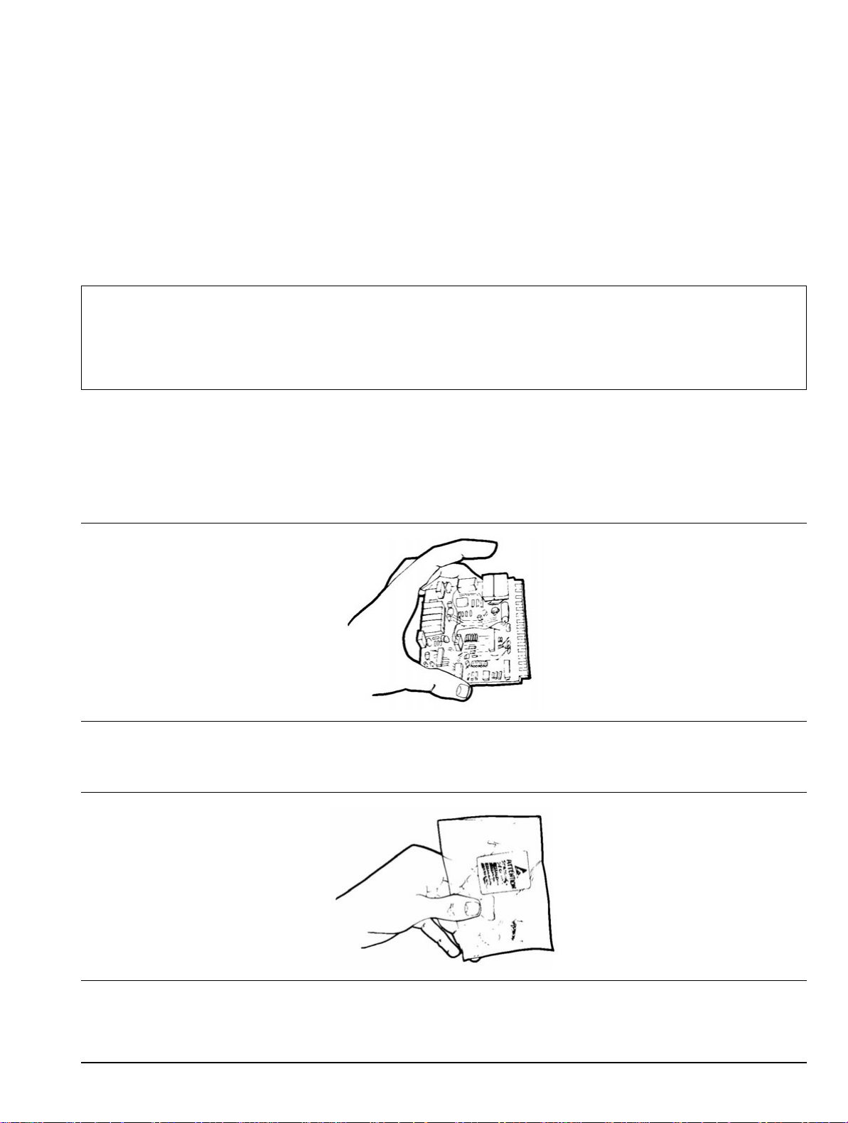
Figure 3-1. Handling a PCB
Handle PCBs only by the edges. Do not handle by the edge connectors.
Figure 3-2. Static-Shielded Container
MS2711B Maintenance 10580-00072 C 3-1
Page 40

Static Sensitive Assembly Handling Removal and Replacement
Transport and store PCBs in static-shielded containers only.
Figure 3-3. Static-Discharge W ristband
Always wear a static-discharge wristband when working with static sensitive components.
Additional Precautions
• Do not handle static sensitive components in areas where the floor or work surface covering is capable of
generating a static charge.
• Keep work areas clean and free of any objects capable of holding or storing a static charge.
3-2 10580-00072 C MS2711B Maintenance
Page 41
Removal and Replacement Battery Pack Removal And Replacement
3-3 Battery Pack Removal And Replacement
This procedure provides instructions for removing and replacing the Spectrum Analyzer battery pack.
Note
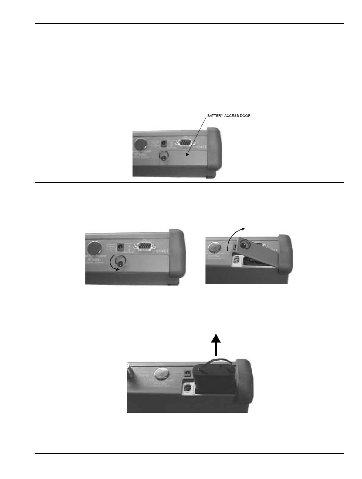
1. With the Spectrum Analyzer standing upright on a stable surface, locate the battery access door
(Figure 3-4).
Figure 3-4. Opening the Battery Access Door
2. Lift up the access door handle and rotate it 90 degrees counterclockwise, as illustrated in Figure 3-4.
3. Lift the door and remove the door, as illustrated in Figure 3-5.
Procedures in this manual may apply to many similar instruments. Photos and illustrations used are
representative and may show instruments other than the MS2711B Spectrum Analyzer.
Figure 3-5. Battery Access Door, Opening
4. Grasp the battery lanyard and pull the battery straight up and out of the unit, as illustrated in
Figure 3-6.
Figure 3-6. Removing the Battery
MS2711B Maintenance 10580-00072 C 3-3
Page 42

Battery Pack Removal And Replacement Removal and Replacement
5. Replacement is the opposite of removal. Note the orientation of the battery contacts, and be sure to insert
the new battery with the contacts facing the rear of the unit (Figure 3-7).
Figure 3-7. Battery Contacts
Battery Information
The following information relates to the care and handling of the instrument battery, and NiMH batteries in
general.
• The Nickel Metal Hydride (NiMH) battery that is supplied with the MS2711B is shipped in a discharged
state. Before using the MS2711B Spectrum Analyzer, the internal battery must first be charged for
three hours, either in the instrument or in the optional battery charger (Anritsu part
number: 2000-1029).
• Use only Anritsu approved battery packs.
• Recharge the battery only in the instrument or in an Anritsu approved charger.
• With a new NiMH battery, full performance is achieved after three to five complete charge and discharge
cycles.
• When either the MS2711B or the charger is not in use, disconnect it from the power source.
• Do not charge batteries for longer than 24 hours. Overcharging may shorten battery life.
• If left unused, a fully charged battery will discharge itself over time.
• Temperature extremes affect the ability of the battery to charge. Allow the battery to cool down or warm
up as necessary before use or charging.
• Discharge an NiMH battery from time to time to improve battery performance and battery life.
• The battery can be charged and discharged hundreds of times, but it will eventually wear out.
• The battery may need to be replaced when the operating time between charges becomes noticeably
shorter than normal.
• Never use a damaged or worn out charger or battery.
• Storing the battery in extreme hot or cold places reduces the capacity and the lifetime of the battery.
• Never short-circuit the battery terminals.
• Do not drop, mutilate, or attempt to disassemble the battery.
• Do not dispose of batteries in a fire!
• Batteries must be recycled or disposed of properly. Do not place batteries in household garbage.
• Always use the battery for its intended purpose only.
3-4 10580-00072 C MS2711B Maintenance
Page 43

Removal and Replacement Battery Pack Removal And Replacement
Battery Testing Procedure
1. With the instrument off and the battery installed, connect the Universal AC Adapter to the 12.5-15VDC
(1100 mA) connector. The External Power LED and the Battery Charging LED will light.
If the Battery Charging LED does not illuminate, then the battery state of charge may be too
low to immediately start full charging. Leaving the unit connected to AC power for several
Note
2. Disconnect the AC-DC Adapter when the Battery Charging LED turns off, indicating that the battery is
fully charged.
3. Press and hold the ESCAPE/CLEAR key, then press the ON/OFF key to turn on the instrument. This sets
the instrument to the factory preset state. Press Enter when prompted to continue.
4. Press the SYS key, followed by the STATUS soft key. Verify that the indicated battery charge is ≥ 80%. If
the value is 80% or above, then press the ESCAPE/CLEAR key and continue with this procedure. If the
value is lower than 80%, then a discharge/charge cycle may be needed in order to improve the battery
capacity. Completely discharge the battery, as described in Step 5 and Step 6 below, and then recharge
the battery as described in Step 1 and Step 2. If the battery capacity does not increase after a
discharge/charge cycle, then replace the battery.
5. Press the START CAL key (to keep the instrument from going into HOLD mode) and make note of the test
start time.
hours may bring the battery up to a level where full charging can begin. Turn the unit off and
back on to see if the Battery Charging LED illuminates, thereby indicating that a full charge
cycle has begun.
6. When the instrument display fades and the instrument switches itself off, make note of the test stop
time.
7. The total test time (Step 5 and Step 6) should be ≥ 2.5 hours. If the total test time is < 2.5 hours, then
replace the battery.
MS2711B Maintenance 10580-00072 C 3-5
Page 44
Front Panel Assembly Removal And Replacement Removal and Replacement
3-4 Front Panel Assembly Removal And Replacement
This procedure provides instructions for removing and replacing the Spectrum Analyzer front panel assembly.
With the front panel assembly removed, the LCD display, keypad PCB, keypad membrane, and main PCB
assemblies can be removed and replaced.
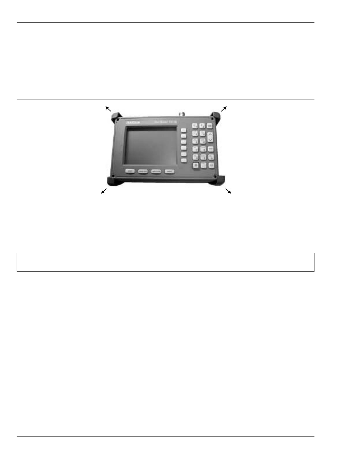
1. Place the Spectrum Analyzer face up on a work surface.
2. Remove the four rubber corner bumpers by carefully sliding the bumpers off of the case corners
(Figure 3-8).
Figure 3-8. Removing the Corner bumpers
3. With the bumpers removed, the access holes for the case screws are revealed. Use a Phillips screwdriver
to remove the four screws that secure the two halves of the Spectrum Analyzer case together.
4. Carefully lift up on the right side (as viewed from the front) of the front half of the case and begin to
separate the two halves.
Caution
5. Carefully depress the latch tab and disconnect the LCD display cable from J12 on the main PCB.
6. Carefully disconnect the keypad interface cable from J1 on the main PCB.
7. Carefully disconnect the speaker cable from J23 on the main PCB.
8. Carefully disconnect the LCD display backlight cable from J15 on the main PCB.
Do not force or pull the two halves of the case apart because delicate cables are attached between
the two halves. These cables must be disconne cted first. Refer to Figure 3-9.
3-6 10580-00072 C MS2711B Maintenance
Page 45

Removal and Replacement Front Panel Assembly Removal And Replacement
Figure 3-9. Spectrum Analyzer Front Panel Cable Connections
9. Remove the front panel assembly.
10. Reverse the above steps to replace the front panel assembly.
Note
Figure 3-10. Corner Bumper Detail
The corner bumpers mount only one way. That is, the raised area inside one end of the bumper
(Figure 3-10) is made to conform to the contour of only the front cover.
MS2711B Maintenance 10580-00072 C 3-7
Page 46

LCD Assembly Replacement Removal and Replacement
3-5 LCD Assembly Replacement
This procedure provides instructions for removing and replacing the Liquid Crystal Display (LCD) after the
front panel assembly has been separated from the Spectrum Analyzer.
1. Remove the front panel assembly as directed in section “Front Panel Assembly Removal And
Replacement” on page 3-6.
2. Place the front panel assembly face down on a protected work surface.
3. Remove the 14 Phillips screws that attach the backing plate to the front panel assembly.
4. Release the LCD display cable and speaker cable from the retaining clips on the front panel backing
plate.
Figure 3-11. Front Panel Backing Plate
5. Remove the front panel backing plate, carefully feeding the LCD cable through the access hole in order to
avoid damage to the cable or its connector.
6. Remove the rubber cushion pad from the LCD assembly and remove the assembly.
7. Reverse the above steps to install the replacement assembly.
3-8 10580-00072 C MS2711B Maintenance
Page 47

Removal and Replacement Key Pad PCB Replacement
3-6 Key Pad PCB Replacement
This procedure provides instructions for removing and replacing the key pad PCB.
1. Remove the front panel assembly as directed in section “Front Panel Assembly Removal And
Replacement” on page 3-6.
2. Place the front panel assembly face down on a protected work surface.
3. Remove the 14 Phillips screws that attach the backing plate to the front panel assembly.
4. Release the LCD display cable and speaker cable from the retaining clips on the front panel backing plate
(Figure 3-12).
5. Remove the front panel backing plate, carefully feeding the LCD cable through the access hole to avoid
damage to the cable or its connector.
6. Remove the rubber cushion pad from the key pad PCB and remove the PCB.
Figure 3-12. Front Panel Keypad PCB Location
7. Reverse the above steps to install the replacement assembly. Take care to position the speaker and
speaker cable properly.
MS2711B Maintenance 10580-00072 C 3-9
Page 48
Key Pad Membrane Replacement Removal and Replacement
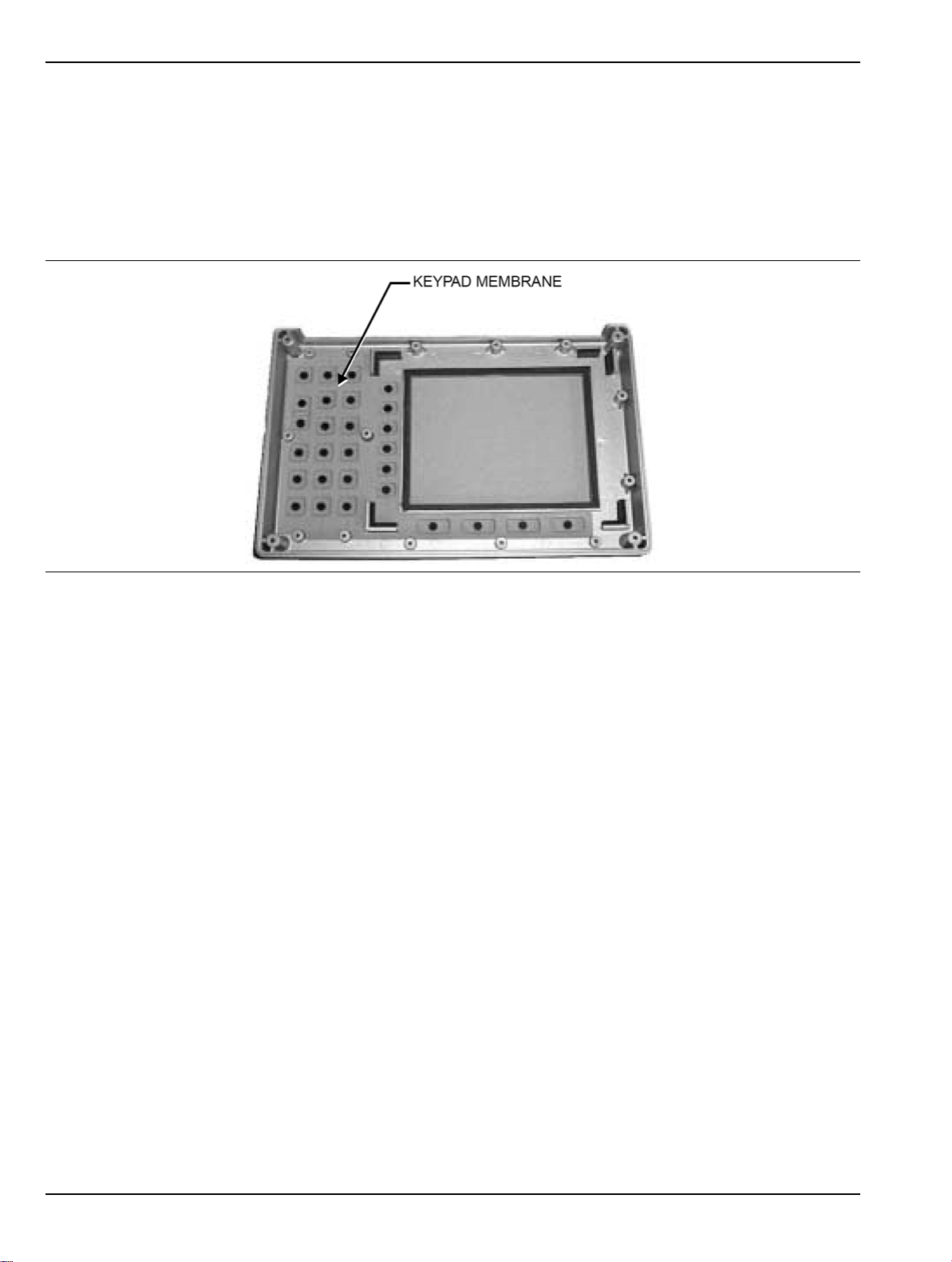
3-7 Key Pad Membrane Replacement
This procedure provides instructions for replacing the key pad membrane.
1. Remove the front panel assembly as directed in section “Front Panel Assembly Removal And
Replacement” on page 3-6.
2. Remove the key pad PCB as directed in section “Key Pad PCB Replacement” on page 3-9.
3. Remove the keypad membrane by gently pulling the membrane up and out of the holes in the front panel.
if
Figure 3-13. Front Panel Keypad Membrane
4. Reverse the above steps to install the replacement membrane.
3-10 10580-00072 C MS2711B Maintenance
Page 49

Removal and Replacement PCB Assembly Replacement
3-8 PCB Assembly Replacement
This procedure provides instructions for replacing the PCB assembly with the connector panel attached. For an
MS2711B with no options, or for an MS2711B with only Option 20, the PCB assembly consists of two PCBs
(Control and Spectrum Analyzer). For an MS2711B with Option 5 or Option 8 installed, the assembly consists
of three PCBs (Control, Spectrum Analyzer, and Preamplifier or Power Monitor). These PCB assemblies must
always be replaced as a matched set.
1. Remove the front panel assembly as directed in Section “Front Panel Assembly Removal And
Replacement” on page 3-6.
2. Disconnect the battery connector from J13 on the main PCB.
3. Disconnect the semi-rigid coaxial cable from the RF In connector on the connector panel.
Note
Figure 3-14. Cable Connections
4. Remove the three PCB mounting screws (Figure 3-15) and remove the Control PCB assembly with the
connector panel attached.
For an MS271 1 B with Option 8 installed, disconnect the semi-rigid cable from the Pre-Amplifier PCB
as shown in Figure 3-14.
Figure 3-15. Control PCB
MS2711B Maintenance 10580-00072 C 3-11
Page 50
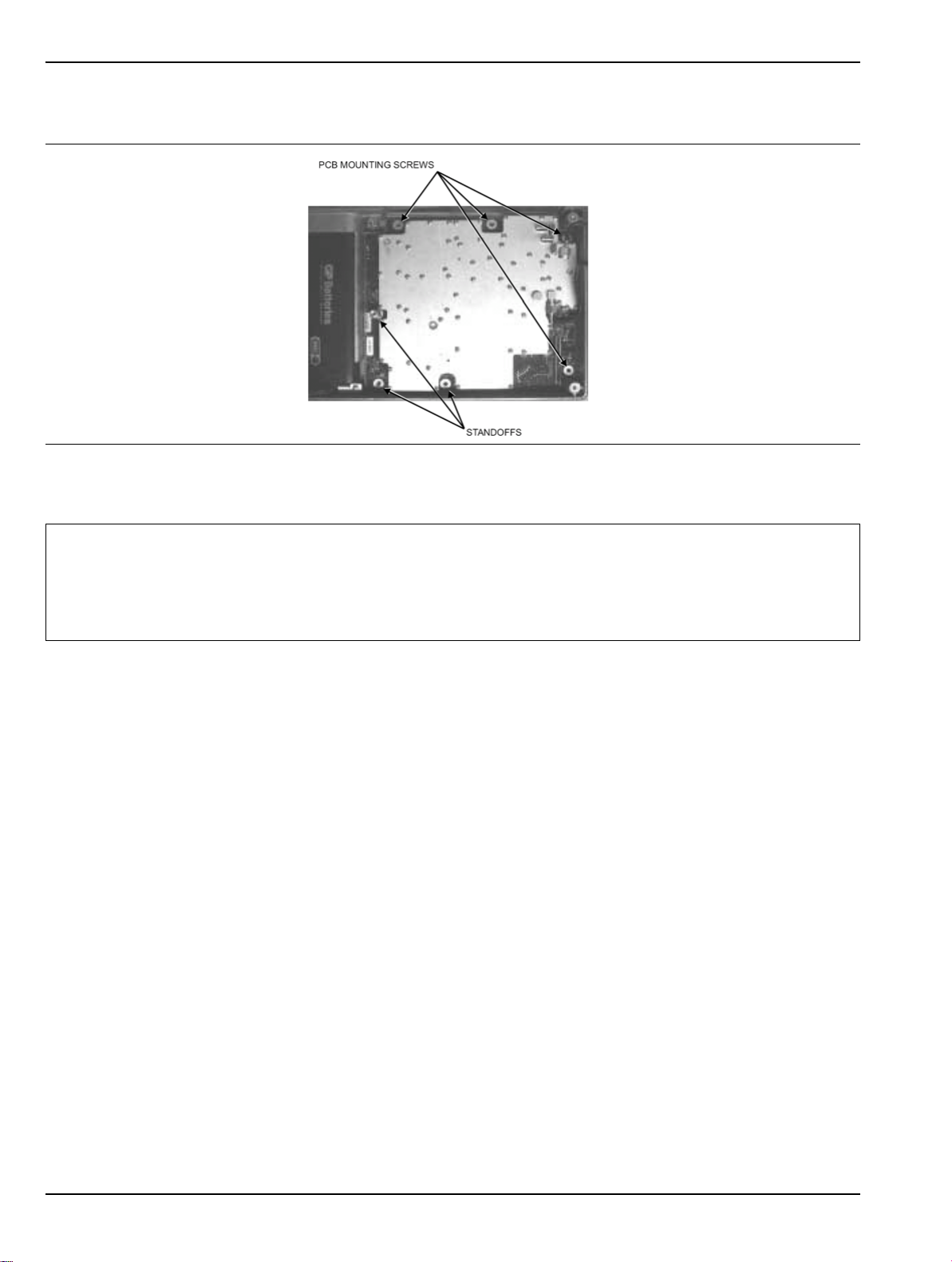
PCB Assembly Replacement Removal and Replacement
5. Remove the three 0.25-inch standoffs and four Phillips screws (Figure 3-16) and remove the Spectrum
Analyzer PCB.
Figure 3-16. Spectrum Analyzer PCB
6. Reverse the above steps to install the new Control and Spectrum Analyzer PCBs.
Note
The Control and Spectrum Analyzer PCBs are adjusted as a matched set at the factory and
must always be replaced together.
The PCB connector panel fits into grooves in the two halves of the Spectrum Analyzer case.
Make sure that the panel is correctly aligned with the grooves before reassembling the two
halves together.
3-12 10580-00072 C MS2711B Maintenance
Page 51

Appendix A Test Records
This appendix provides test records that can be used to record the performance of the MS2711B Maintenance.
Anritsu Company recommends that you make a copy of the following test record pages and document the
measurements each time a Performance Verification is performed. Continuing to document this process each
time it is performed will provide a detailed history of the instrument performance.
MS2711B Maintenance 10580-00072 C A-1
Page 52

Preamplifier (Option 8) Level Accuracy Test Settings Test Records
MS2711B
Firmware Revision: ________________ Operator: ________________ Date: ______________
Maintena
nce
Serial Number: ________________ Options: ___________________________________________________
A-1 Preamplifier (Option 8) Level Accuracy Test Settings
Table A-1. Preamplifier Level Accuracy Test Settings
Freq
(MHz) Output Power at Source Output Power at Attenuator Attenuator Insertion Loss
50
500
1000
1500
2000
2500
2950
A-2 10580-00072 C MS2711B Maintenance
Page 53

Test Records Preamplifier (Option 8) Level Accuracy Test Characterization
MS2711B
Firmware Revision: ________________ Operator: ________________ Date: ______________
Maintena
nce
Serial Number: ________________ Options: ___________________________________________________
A-2 Preamplifier (Option 8) Level Accuracy Test Characterization
Table A-2. Attenuator Characterization
Desired
Freq
(MHz)
1000 –50
T est Level
(dBm) Attenuator Insertion Loss Required Power Meter Level (dBm)
50 –50
–55
–60
500 –50
–55
–60
–55
a
–60
1500 –50
–55
–60
2000 –50
–55
–60
2500 –50
–55
–60
2950 –50
–55
–60
a.Required Power meter Level = Desired Test level + Attenuator Insertion Loss
MS2711B Maintenance 10580-00072 C A-3
Page 54

Preamplifier (Option 8) Level Accuracy Test Results Test Records
MS2711B
Firmware Revision: ________________ Operator: ________________ Date: ______________
Maintena
nce
Serial Number: ________________ Options: ___________________________________________________
A-3 Preamplifier (Option 8) Level Accuracy Test Results
Table A-3. Preamplifier Level Accuracy Test Results
Desired
Freq
(MHz)
Test Level
(dBm)
50 –50
500 –50
1000 –50
–55
–60
–55
–60
–55
MS2711B
Ref Level
(dBm) M1 Reading
–40
–45
–50
–40
–45
–50
–40
–45
–60
1500 –50
–55
–60
2000 –50
–55
–60
2500 –50
–55
–60
2950 –50
–55
–60
–50
–40
–45
–50
–40
–45
–50
–40
–45
–50
–40
–45
–50
A-4 10580-00072 C MS2711B Maintenance
Page 55

Test Records Tracking Generator Option Level Accuracy
MS2711B
Maintena
nce
Serial Number: ________________ Options: ___________________________________________________
Firmware Revision: ________________ Operator: ________________ Date: ______________
A-4 Tracking Generator Option Level Accuracy
Table A-4. Tracking Generator Option Level Accuracy
Output
(dBm) Spec.
0 ±1.5 dB
–10 ±1.5 dB
–20 ±1.5 dB
–30 ±1.5 dB
–40 ±1.5 dB
–50 ±4.0 dB
10
MHz
100
MHz
500
MHz
1000
MHz
1500
MHz
2060
MHz
2061
MHz
2500
MHz
3000
MHz
A-5 Tracking Generator Harmonics and Spurious Test
Table A-5. Tracking Generator Harmonics and Spur
Fundamental
Freq.
(MHz) Spec. 750 790 830 870 910 950 1600 1680 1760 1840 1920 2000
Harmonics
Level ≤ –20 dBc
Other
Spurious Level ≤ –20 dBc
MS2711B Maintenance 10580-00072 C A-5
Page 56

Tracking Generator Harmonics and Spurious Test Test Records
A-6 10580-00072 C MS2711B Maintenance
Page 57

Page 58

Printed on Recycled Paper with Vegetable Soybean Oil Ink
Anritsu Company
Morgan Hill, CA 95037-2809
490 Jarvis Drive
http://www.anritsu.com/
USA
 Loading...