

Technical Data Sheet
Microwave Universal
USB Power Sensors
Low Cost, Compact, and Highly Accurate Power Sensors
for RF and Microwave Applications
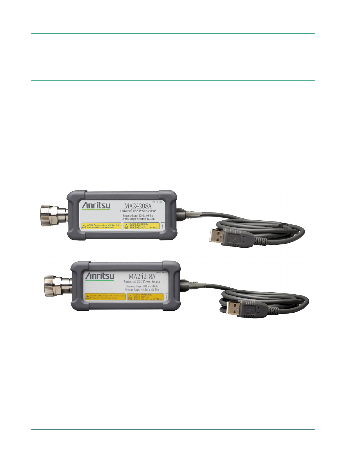
MA24208A
True-RMS, 10 MHz to 8 GHz
MA24218A
True-RMS, 10 MHz to 18 GHz
MA24208A/MA24218A Specifications
Introduction
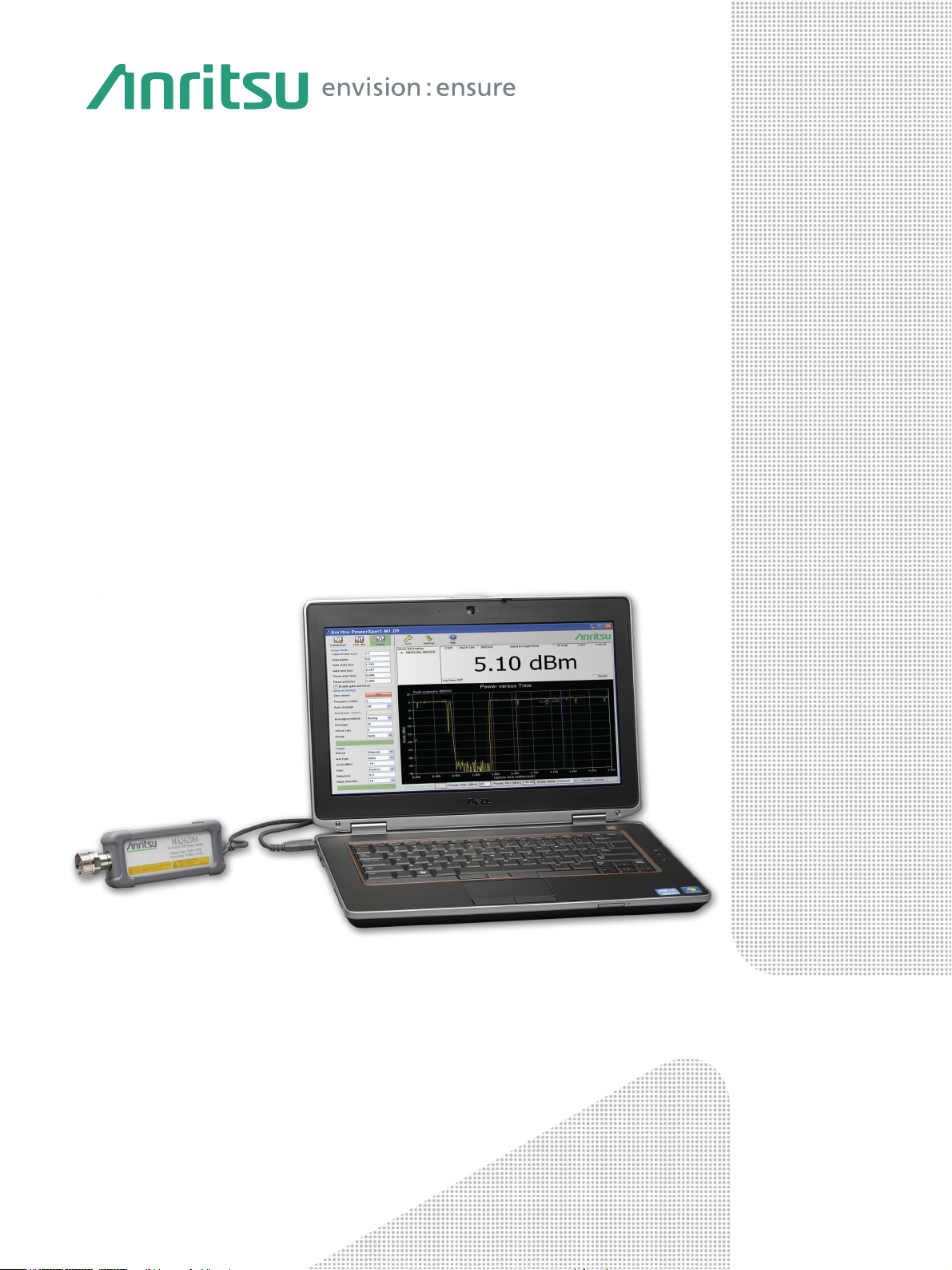
The MA24208A and MA24218A Universal USB Power sensors are designed to provide accurate average power
measurements from 10 MHz to 8 GHz and 18 GHz, respectively, over 80 dB of dynamic range. The sensors employ a
patented “triple path” architecture that provides True-RMS measurements over the entire frequency and dynamic range
(similar to thermal sensors), enabling users to make highly accurate average power measurements for CW, multi-tone,
and digitally modulated signals up to 18 GHz.
Features and Benefits
• Broad Frequency Range (10 MHz to 18 GHz): Ideal for general purpose, aerospace and defense, satellite and wireless
communications applications
• True RMS Measurements over 80 dB Dynamic Range: Enables average power measurement on CW, multi-tone, and digitally
modulated signals - independent of modulation bandwidth
• Best-in-Class Damage Protection (+30 dBm CW, +34 dBm peak < 10 µs): Protects instrumentation investment
• No Zeroing Required (for signals > –45 dBm) and Elimination of 1 mW Reference Calibration: Reduces test time and handling in
production while maintaining absolute accuracy
• Advanced Trigger Capabilities: Facilitates time dependent power measurements (for example, GSM, WiMAX, TD-SCDMA, and LTE)
• NIST Traceable Calibration: Provides high-accuracy measurements
• Easy to Use with PC or Select Anritsu Handheld Instruments: No benchtop power meter unit needed
• Silicone Protective Covering (removable): Provides additional field durability
• External Trigger Latching: For pulses as narrow as 20 ns
MA24208A and MA24218A Universal USB Power Sensors
2 of 9 PN: 11410-00841 Rev. D MA24208A/MA24218A TDS

Specifications MA24208A/MA24218A
Table of Contents
Definitions. . . . . . . . . . . . . . . . . . . . . . . . . . . . . . . . . . . . . . . . . . . . . . . . . . . . . . . . . . . . . . . . . . . . . . . . . . . . . . . . . . . . . 3
Sensor Specifications . . . . . . . . . . . . . . . . . . . . . . . . . . . . . . . . . . . . . . . . . . . . . . . . . . . . . . . . . . . . . . . . . . . . . . . . . . . 4
Measurement Uncertainty . . . . . . . . . . . . . . . . . . . . . . . . . . . . . . . . . . . . . . . . . . . . . . . . . . . . . . . . . . . . . . . . . . . . . . . 5
PowerXpert™ . . . . . . . . . . . . . . . . . . . . . . . . . . . . . . . . . . . . . . . . . . . . . . . . . . . . . . . . . . . . . . . . . . . . . . . . . . . . . . . . . . 6
General . . . . . . . . . . . . . . . . . . . . . . . . . . . . . . . . . . . . . . . . . . . . . . . . . . . . . . . . . . . . . . . . . . . . . . . . . . . . . . . . . . . . . . . 7
Operational Requirements. . . . . . . . . . . . . . . . . . . . . . . . . . . . . . . . . . . . . . . . . . . . . . . . . . . . . . . . . . . . . . . . . . . . . . . 7
Regulatory Compliance. . . . . . . . . . . . . . . . . . . . . . . . . . . . . . . . . . . . . . . . . . . . . . . . . . . . . . . . . . . . . . . . . . . . . . . . . . 7
Ordering Information . . . . . . . . . . . . . . . . . . . . . . . . . . . . . . . . . . . . . . . . . . . . . . . . . . . . . . . . . . . . . . . . . . . . . . . . . . . 8
Optional Accessories. . . . . . . . . . . . . . . . . . . . . . . . . . . . . . . . . . . . . . . . . . . . . . . . . . . . . . . . . . . . . . . . . . . . . . . . . . . . 8
Definitions
Warm-Up Time 60 minutes
Operating Temperature Range 0 °C to 50 °C
Characteristic Performance Characteristic specifications are not tested and are not warranted.
ISO GUM Measurement Uncertainty Zero and Noise uncertainty expressed with three sigma confidence level.
Calibration Cycle Anritsu recommended calibration interval is 12 months.
All specifications and characteristics apply under the following conditions, unless otherwise stated:
Average and Relative Power uncertainty expressed with two sigma confidence level.
All specifications subject to change without notice. For the most current data sheet, please visit the Anritsu
www.anritsu.com
web site:
Notes MA24208A and MA24218A sensors may have degraded performance when dropped without the removable
protective covering. This cover is required for warranted operation.
MA24208A/MA24218A TDS PN: 11410-00841 Rev. D 3 of 9

MA24208A/MA24218A Specifications
Sensor Specifications
Frequency
MA24208A 10 MHz to 8 GHz
MA24218A 10 MHz to 18 GHz
Power Measurement
Dynamic Range –60 dBm to +20 dBm
VSWR, max 1.17:1 1.12:1 1.22:1 1.25:1
Measurement Range 1 +20 dBm to +4 dBm approximate
Measurement Range 2 <+4 dBm to –16 dBm approximate
Measurement Range 3 <–16 dBm to –60 dBm approximate
Damage Levels at RF Port +30 dBm, ±20 V DC (+34 dBm peak < 10 μs pulse and 10 % duty cycle), minimum
≤150 MHz >150 MHz to 2 GHz >2 GHz to 12.4 GHz >12.4 GHz to 18 GHz
Auto and fixed ranging available
Response
Signal Channel Rise Time 8 μs characteristic
Sampling Rate 140 kS/s
Trigger
Arm Type (for Internal/External) Auto, Single, Multiple, Standby
Source1Bus, Continuous, Internal, External
Internal Trigger
Dynamic Range –35 dBm to +20 dBm
Level Accuracy ±0.5 dB characteristic
Slope Positive or Negative
Delay Range –5 ms to +10 s
Delay Resolution 10 μs
Hysteresis 0 to 10 dB, with 0.1 dB resolution
Trigger Hold Off 0 to 10 sec, with 0.01 ms resolution
External Trigger
External Trigger Input MCX (female), 5.5 V maximum
High Level Input Voltage 2.3 V min, 3.0 V max
Low Level Input Voltage 1.3 V min, 1.6 V max
Trigger Repetition Period 7.1 μs min
Impedance 4 kΩ nominal
Type TTL/CMOS
Slope Positive or Negative
Delay Range –5 ms to +10 s
Delay Resolution 10 μs
2
Latency
Trigger Pulse Width 20 ns min
Trigger Hold Off 0 s to 10 s with 0.01 ms resolution
7.1 μs max
1. Bus trigger is not available in PowerXpert application.
2. Latency is defined as the time delay between the defined edge of the applied trigger and the sensor switching into the triggered state.
4 of 9 PN: 11410-00841 Rev. D MA24208A/MA24218A TDS

Specifications MA24208A/MA24218A
Measurement Uncertainty
Average Power (dB)3Over 0 °C to 50 °C ambient temperature range:
Range (dBm) ≤0.05 GHz >0.05 to 2 GHz >2 to 12.4 GHz >12.4 to 18 GHz
–60 to <–16 0.14 0.14 0.14 0.17
–16 to <+4 0.14 0.14 0.13 0.13
+4 to +20 0.14 0.15 0.15 0.14
Over 20 °C to 30 °C ambient temperature range:
Range (dBm) ≤0.05 GHz >0.05 to 2 GHz >2 to 12.4 GHz >12.4 to 18 GHz
–60 to <–16 0.13 0.12 0.14 0.14
–16 to <+4 0.11 0.10 0.13 0.11
+4 to +200.110.100.100.11
Relative Power (dB)
3
≤0.05 GHz:
Over 0 °C to 50 °C Over 20 °C to 30 °C
Range (dBm) +4 to +20 –16 to <+4 –60 to <–16 +4 to +20 –16 to <+4 –60 to <–16
–60 to <–16 0.14 0.13 0.03 0.08 0.09 0.03
–16 to <+4 0.14 0.04 0.13 0.06 0.03 0.09
+4 to +200.050.140.140.050.060.08
>0.05 GHz to 2 GHz:
Over 0 °C to 50 °C Over 20 °C to 30 °C
Range (dBm) +4 to +20 –16 to <+4 –60 to <–16 +4 to +20 –16 to <+4 –60 to <–16
–60 to <–16 0.16 0.16 0.03 0.11 0.12 0.03
–16 to <+4 0.17 0.05 0.16 0.09 0.04 0.12
+4 to +20 0.06 0.17 0.16 0.06 0.09 0.11
>2 GHz to 12.4 GHz:
Over 0 °C to 50 °C Over 20 °C to 30 °C
Range (dBm) +4 to +20 –16 to <+4 –60 to <–16 +4 to +20 –16 to <+4 –60 to <–16
–60 to <–16 0.16 0.16 0.04 0.12 0.14 0.04
–16 to <+4 0.17 0.05 0.16 0.10 0.04 0.14
+4 to +20 0.06 0.17 0.16 0.07 0.10 0.12
>12.4 GHz to 18 GHz:
Over 0 °C to 50 °C Over 20 °C to 30 °C
Range (dBm) +4 to +20 –16 to <+4 –60 to <–16 +4 to +20 –16 to <+4 –60 to <–16
–60 to <–16 0.14 0.15 0.04 0.12 0.14 0.04
–16 to <+4 0.11 0.06 0.15 0.10 0.05 0.14
+4 to +20 0.06 0.11 0.14 0.06 0.10 0.12
4
Zero
Set Drift
Range (dBm) Watts dBm Watts dBm
–60 to <–16 3.32E-10 –64.78 3.44E-10 –64.64
–16 to <+4 3.87E-08 –44.12 4.29E-08 –43.67
+4 to +20 1.07E-06 –29.70 9.96E-07 –30.02
5
Noise
Range (dBm) Watts
–60 to <–16 1.23E-10
–16 to <+4 1.01E-08
+4 to +20 8.56E-07
Effect of Digital Modulation
6
Range (dBm) dB
–60 to <–16 –0.048 to 0.080
–16 to <+4 –0.038 to 0.088
+4 to +20 –0.055 to 0.067
3. Power uncertainty expressed with two sigma confidence level for CW measurement after zero operation Includes calibration factor and linearity over temperature uncertainties,
but not the effects of mismatch, zero set and drift, or noise.
4. Zero uncertainty expressed with three sigma confi dence level. One hour warm-up followed by a Zero operation. Measured with 256 averages and 40 ms aperture and with the
temperature kept within ±1 °C..
Zero Set: Average of the reported power over one hour.
Zero Drift: Two sigma value of the reported power over one hour.
5. Two sigma noise at 10.2 seconds of integration time (integration time = aperture time x averaging number). Effect of noise can be reduced by increasing the number of averages
and/or increasing the aperture time. Noise is inversely proportional to the square root of number of ADC samples used per measurement; the number of ADC samples per
measurement is the product of the sample rate, aperture time, and number of averages used. Noise uncertainty is expressed with three sigma confidence level.
6. Measurement error with reference to a CW signal of equal power and frequency between 20 °C to 30 °C in Normal mode and average power ≤+20 dBm. In general, the error
caused by modulation depends on the peak to average power ratio and RF bandwidth of the signal.
MA24208A/MA24218A TDS PN: 11410-00841 Rev. D 5 of 9

MA24208A/MA24218A Specifications
PowerXpert™
PC Requirements
(version 3.0 or greater)
Processor and RAM Minimum: Equivalent to Intel® Pentium® III with 1 GB RAM or Intel® Pentium® IV with 512 MB RAM
Operating System Microsoft® Windows® 8, Windows® 7, and Windows® XP
Hard-Disk Free Space 100 MB minimum
Display Resolution 1024 × 768 minimum
System
Measurand Average power
Measurement Resolution 0.01 dB max via PowerXpert™, 0.001 dB max via remote command
Offset Correction
Averaging Auto, Manual
Number of Averages (Manual)
Auto Average Resolution
Auto Average Source Timeslot Number: 1 to 128
Continuous Average Mode
Duty Cycle Correction 0.01 % to 100 %
Aperture Time 0.01 ms to 1 s
Measurement Time
Buffer Size 8192
Scope Mode
Capture Time 0.01 ms to 1 s
Data Points 1 to 16,384
Resolution 0.01 ms max
Measurement Time
Timeslot Mode
Maximum Number of Slots 128
Maximum Capture Time 1000 ms (slot width x number of slots)
Measurement Time
Slot Width 0.01 ms to 100 ms
Resolution 0.01 ms max via remote command
Exclusion Periods Start Exclusion: 0 ms to 10 ms
List Mode
Number of Measurements 1 to 1000
Input Parameters Frequency (GHz), aperture time (ms), averages
Recommended: Equivalent to Intel® Pentium® IV with 1 GB RAM
Interface USB 2.0 high speed
7
–100 dB to +150 dB
Type Moving, Repeat
8
1 to 65,536
9
1 dB, 0.1 dB, 0.01 dB
Scope Data Point Number: 1 to 16,384
10
N x (aperture time x Ct) + 0.375 ms + T
Continuous: >1,600 readings/s (minimum aperture, one average)
Buffered: >11,000 readings/s (minimum aperture, one average)
11
N x (capture time x Ct) + (Pn x 0.042 ms) + T
0.01 ms max via PowerXpert™
End Exclusion: 0 ms to 10 ms
12
N x (slot width x number of slots x Ct) + (Pn x 0.064 ms) + T
com
com
com
7. Offset correction feature is available only through the PowerXpert application. There is no remote command for it in the sensor firmware.
8. Maximum number of averages allowed in Continuous Average mode and Timeslot mode is 65,536. In Scope mode, the maximum number of averages is equal to 16,777,216
divided by the number of data points.
9. Averaging resolution of 0.001 dB is not available with the PowerXpert application. It is defined as the place after the decimal to which the reading becomes stable.
For example, if 0.01 is selected, then the reading will typically be stable within ±0.01 dB. Please refer to the remote operation chapter in the user guide for information regarding
access to this feature.
10. Speed is defined as the data throughput at the “A” end of the USB A to Micro-B Cable (p/n 2000-2010-R), where:
Number of Repeat Averages = N (N = 1 for moving average mode)
Capture Time Coefficient = Ct = 1.62
Command Processing Time = T
Speed may vary depending on the speed of and load on the CPU controlling the sensor. Specified results obtained with Intel® Core™ i5-3550 CPU running at 3.30 GHz
11. Speed is defined as the data throughput at the “A” end of the USB A to Micro-B Cable (p/n 2000-2010-R), where:
Number of Repeat Averages = N (N = 1 for moving average mode)
Capture Time Coefficient = Ct = 1.645
Number of Points = Pn
Command Processing Time = T
12. Speed is defined as the data throughput at the “A” end of the USB A to Micro-B Cable (p/n 2000-2010-R), where:
Number of Repeat Averages = N (N = 1 for moving average mode)
Capture Time Coefficient = Ct = 1.625
Number of Points = Pn
Command Processing Time = T
com
com
com
= 0.2 ms
= 0.24 ms
= 0.29 ms
6 of 9 PN: 11410-00841 Rev. D MA24208A/MA24218A TDS

Specifications MA24208A/MA24218A
External
Trigger Input
(TTL/CMOS)
N Type connector designed for use with a torque wrench
ensuring repeatable connections
Trigger
Output
USB Micro-B port for connectivity to host
(PC or Anritsu handheld instrument)
Color LED
reports functional
status of the sensor
General
RF Connector N male
Interface to Host USB 2.0 high speed
Current Consumption 410 mA to 450 mA characteristic (20 ºC to 30 ºC)
Size 110 mm x 46 mm x 25.6 mm, excluding N connector and silicone protective covering
Weight 397 g (0.88 lb)
Warranty 1 year
Operational Requirements
Operating Temperature Range 0 ºC to 50 ºC
Storage Temperature Range –40 ºC to +71 ºC
Relative Humidity (non-condensing) 45 % at 50 ºC
Altitude 4600 m operational max
Shock 30 g half-sine, 11 ms duration
Vibration Sinusoidal: 5 Hz to 55 Hz, 3 g max
Regulatory Compliance
European Union EMC 2014/30/EU, EN 61326:2013, CISPR 11/EN 55011, IEC/EN 61000-4-2/3/4/5/6/8/11
Australia and New Zealand RCM AS/NZS 4417:2012
South Korea KCC-REM-A21-0004
Tests were performed per MIL-PRF-28800F (Class 3).
75 % at 40 ºC
95 % at 30 ºC
Random: 10 Hz to 500 Hz, 2.34 g rms
Power Spectral Density: 0.01 g
Low Voltage Directive 2014/35/EU
Safety EN 61010-1:2010
RoHS Directive 2011/65/EU
2
/Hz
MA24208A/MA24218A TDS PN: 11410-00841 Rev. D 7 of 9

MA24208A/MA24218A Specifications
Ordering Information
Available Models
MA24208A 8 GHz USB Universal Power Sensor
MA24218A 18 GHz USB Universal Power Sensor
Included Accessories
10585-00021 Quick Start Guide
2000-1605-R 1.5 m BNC(m) to MCX(m) cable
2000-2010-R 1.83 m USB A to Micro-B cable
Available Options
MA24208A-097 Option 97: ISO/IEC 17025 and ANSI/NCSL Z540-1 or ANSI/NCSLI Z540.3
MA24208A-098 Option 98: Standard calibration ISO/IEC 17025 and ANSI/NCSL Z540-1
MA24208A-099 Option 99: Premium calibration ISO/IEC 17025 and ANSI/NCSL Z540-1
MA24218A-097 Option 97: ISO/IEC 17025 and ANSI/NCSL Z540-1 or ANSI/NCSLI Z540.3
MA24218A-098 Option 98: Standard calibration ISO/IEC 17025 and ANSI/NCSL Z540-1
MA24218A-099 Option 99: Premium calibration ISO/IEC 17025 and ANSI/NCSL Z540-1
Optional Accessories
(includes test report, uncertainty data, and accreditation symbol)
(includes test report and uncertainty data)
(includes test report, uncertainty data, and accreditation symbol)
(includes test report and uncertainty data)
Calibrated Torque Wrenches
Power Attenuators
3-1010-123 DC to 8.5 GHz, 30 dB, 50 W, 50 Ω, N(m) to N(f)
3-1010-124 DC to 8.5 GHz, 40 dB, 100 W, 50 Ω, N(m) to N(f)
3-1010-122 DC to 12.4 GHz, 20 dB, 5 W, 50 Ω, N(m) to N(f)
42N50-20 DC to 18 GHz, 20 dB, 5 W, 50 Ω, N(m) to N(f)
42N50A-30 DC to 18 GHz, 30 dB, 50 W, 50 Ω, N(m) to N(f)
41KB-3 DC to 26.5 GHz, 3 dB, 50 Ω, K(m) to K(f)
41KB-6 DC to 26.5 GHz, 6 dB, 50 Ω, K(m) to K(f)
41KB-10 DC to 26.5 GHz, 10 dB, 50 Ω, K(m) to K(f)
41KB-20 DC to 26.5 GHz, 20 dB, 50 Ω, K(m) to K(f)
43KB-3 DC to 26.5 GHz, 3 dB, 50 Ω, K(m) to K(f)
43KB-6 DC to 26.5 GHz, 6 dB, 50 Ω, K(m) to K(f)
43KB-10 DC to 26.5 GHz, 10 dB, 50 Ω, K(m) to K(f)
43KB-20 DC to 26.5 GHz, 20 dB, 50 Ω, K(m) to K(f)
Precision Coaxial Adapters
510-90-R DC to 3.3 GHz, N(m) to 7/16 DIN(f)
510-91-R DC to 3.3 GHz, N(f) to 7/16 DIN(f)
510-92-R DC to 3.3 GHz, N(m) to 7/16 DIN(m)
510-93-R DC to 3.3 GHz, N(f) to 7/16 DIN(m)
33NFNF50B DC to 18 GHz, N(f) to N(f)
33NNF50B DC to 18 GHz, N(m) to N(f)
33NN50B DC to 18 GHz, N(m) to N(m)
34AN50 DC to 18 GHz, GPC-7 to N(m)
34ANF50 DC to 18 GHz, GPC-7 to N(f)
34NFK50 DC to 18 GHz, N(f) to K(m)
34NFKF50 DC to 18 GHz, N(m) to K(f)
34NK50 DC to 18 GHz, N(m) to K(m)
34NKF50 DC to 18 GHz, N(m) to K(f)
1091-26-R DC to 18 GHz, N(m) to SMA(m)
1091-27-R DC to 18 GHz, N(m) to SMA(f)
1091-80-R DC to 18 GHz, N(f) to SMA(m)
1091-81-R DC to 18 GHz, N(f) to SMA(f)
01-200 Calibrated torque wrench for N connector
01-204 Calibrated torque wrench for K and V connectors
8 of 9 PN: 11410-00841 Rev. D MA24208A/MA24218A TDS

Training at Anritsu
Anritsu has designed courses to help you stay up to date with technologies important to your job. For available training
courses, visit:
www.anritsu.com/training
• United States
Anritsu Americas Sales Company
450 Century Parkway, Suite 190
Allen, TX 75013, U.S.A.
Phone: +1-800-Anritsu (1-800-267-4878)
• Canada
Anritsu Electronics Ltd.
700 Silver Seven Road, Suite 120
Kanata, Ontario K2V 1C3, Canada
Phone: +1-613-591-2003
Fax: +1-613-591-1006
• Brazil
Anritsu Eletronica Ltda.
Praça Amadeu Amaral, 27 - 1 Andar
01327-010 - Bela Vista - Sao Paulo - SP
Brazil
Phone: +55-11-3283-2511
Fax: +55-11-3288-6940
• Mexico
Anritsu Company, S.A. de C.V.
Blvd Miguel de Cervantes Saavedra #169 Piso 1,
Col. Granada
Mexico, Ciudad de Mexico, 11520, MEXICO
Phone: +52-55-4169-7104
• United Kingdom
Anritsu EMEA L td.
200 Capability Green
Luton, Bedfordshire, LU1 3LU, U.K.
Phone: +44-1582-433200
Fax: +44-1582-731303
• France
Anritsu S.A.
12 avenue du Québec, Bâtiment Iris 1- Silic 612,
91140 Villebon-sur-Yvette, France
Phone: +33-1-60-92-15-50
Fax: +33-1-64-46-10-65
• Germany
Anritsu GmbH
Nemetschek Haus, Konrad-Zuse-Platz 1
81829 München, Germany
Phone: +49-89-442308-0
Fax: +49-89-442308-55
• Italy
Anritsu S.r.l.
Via Elio Vittorini 129, 00144 Roma, Italy
Phone: +39-6-509-9711
Fax: +39-6-502-2425
List Revision Date: 20200602
• Sweden
Anritsu AB
Isafjordsgatan 32C
164 40 Kista, Sweden
Phone: +46-8-534-707-00
• Finland
Anritsu AB
Teknobulevardi 3-5
FI-01530 Vantaa, Finland
Phone: +358-20-741-8100
Fax: +358-20-741-8111
• Denmark
Anritsu A/S
c/o Regus Winghouse, Ørestads Boulevard 73, 4th
floor,
2300 Copenhagen S, Denmark
Phone: +45-7211-2200
• Russia
Anritsu EMEA Ltd.
Representation Office in Russia
Tverskaya str. 16/2, bld. 1, 7th floor
Moscow 125009, Russia
Phone: +7-495-363-1694
Fax: +7-495-935-8962
• Spain
Anritsu EMEA Ltd.
Representation Office in Spain
Paseo de la Castellana, 141.
Planta 5, Edificio Cuzco IV
28046, Madrid, Spain
Phone: +34-91-572-6761
• United Arab Emirates
Anritsu EMEA Ltd.
Dubai Liaison Office
902 Aurora Tower
P O Box: 500311- Dubai Internet City
Dubai, United Arab Emirates
Phone: +971-4-3758479
Fax: +971-4-4249036
• India
Anritsu India Private Limited
6th Floor, Indiqube ETA, No.38/4
Adjacent to EMC2, Doddanekundi, Outer Ring Road
Bengaluru 560048, India
Phone: +91-80-6728-1300
Fax: +91-80-6728-1301
• Singapore
Anritsu Pte. Ltd.
11 Chang Charn Road, #04-01, Shriro House
Singapore 159640
Phone: +65-6282-2400
Fax: +65-6282-2533
• P.R. China (Shanghai)
Anritsu (China) Co., Ltd.
Room 2701-2705, Tower A
New Caohejing International Business Center
No. 391 Gui Ping Road
Shanghai 200233, P.R. China
Phone: +86-21-6237-0898
Fax: +86-21-6237-0899
• P.R. China (Hong Kong)
Anritsu Company Ltd.
Unit 1006-7, 10/F.
Greenfield Tower, Concordia Plaza
No. 1 Science Museum Road
Tsim Sha Tsui East, Kowloon
Hong Kong, P.R. China
Phone: +852-2301-4980
Fax: +852-2301-3545
• Japan
Anritsu Corporation
8-5, Tamura-cho, Atsugi-shi, Kanagawa, 243-0016
Japan
Phone: +81-46-296-6509
Fax: +81-46-225-8352
• South Korea
Anritsu Corporation, Ltd.
5FL, 235 Pangyoyeok-ro
Bundang-gu, Seongnam-si
Gyeonggi-do 13494, South Korea
Phone: +82-31-696-7750
Fax: +82-31-696-7751
• Australia
Anritsu Pty. Ltd.
Unit 20, 21-35 Ricketts Road
Mount Waverley, Victoria 3149, Australia
Phone: +61-3-9558-8177
Fax: +61-3-9558-8255
• Taiwan
Anritsu Company Inc.
7F, No. 316, Sec. 1, NeiHu Rd. Taipei 114, Taiwan
Phone: +886-2-8751-1816
Fax: +886-2-8751-1817
Data subject to change without notice.
For the most recent specifications, visit: www.anritsu.com.
9
9 of 9
® Anritsu All trademarks are registered trademarks of their respective companies.
Copyright January 2021, Anritsu Company, USA. All Rights Reserved.
MA24208A/MA24218A TDS, PN: 11410-00841, Rev. D
Anritsu utilizes recycled paper and environmentally conscious inks and toner.
 Loading...