

Page 1

SC-PC-F
SC-APC-F
FC-PC-F
FC-APC-F
LC-PC-F
ST-PC-F
MU-PC-F
For MU Connector
E2000-PC-F
For E2000 Connector
60-LC-PC-F
Long-LC-PC-F
Long-LC-APC-F
1.25PC-M
1.25APC-M
2.5PC-M
2.5APC-M
E2000-PC-M
E2000-APC-M
Probe tip
Video Inspection Probe (VIP)
Soft case
Probe tip case
Cord
Focus ring
Probe tip
Ring
Floodlight switch
LED
Power button
Power lamp
Cap
Lensed ferrule adapter
Loosen
Tighten
Loosen
Anritsu Corporation h
ttps://
www.anritsu.com
Operation Manual
M-W4068AE-1.0
G0306C
Video Inspection Probe
February 2022 (First Edition)
Copyright © 2022, ANRITSU CORPORATION.
necessary. Confirm the latest information on the following
homepage.
https://www.anritsu.com/en-US/test-measurement/support/dow
nloads?model=MT1000A#downloadSoftware
https://www.anritsu.com/en-US/test-measurement/support/dow
nloads?model=MT1040A#downloadSoftware
https://www.anritsu.com/en-US/test-measurement/support/dow
nloads?model=MT9085%20Series#downloadSoftware
https://www.anritsu.com/en-US/test-measurement/support/dow
nloads?model=MU909014C/14C6/15C/15C6#downloadSoftware
■ Probe Tip
To the VIP tip, connect the probe tip that fits the connector type.
The G0306C Video Inspection Probe comes with the following
standard accessories: Four kinds of bulk-type probe tip and
three kinds of universal-type probe tip. The bulk-type probe tips
are used mainly for inspecting receptacle connector ends that
are located inside of devices and equipment and on the back of
the patch panel. The universal-type probe tips are used for
inspecting plug connector ends of the patch cords.
Bulk type
■ Configuration
The VIP consists of the following component parts.
Video Inspection Probe (VIP) 1
– Standard Accessory –
Soft case 1
Probe tip case 1
Probe tip
FC-PC-F 1
LC-PC-F 1
SC-PC-F 1
SC-APC-F 1
1.25PC-M 1
2.5PC-M 1
2.5APC-M 1
Operation Manual 1
For SC Connector
For FC Connector
For LC Connector
For SC Connector (APC)
For FC Connector (APC)
For ST Connector
■Attaching probe tip
Replacing the probe tip
To replace the probe tip, perform the following procedure:
1. Loosen the ring by rotating it in the direction shown in the
figure.
2. Pull and remove the probe tip.
3. Plug the ferrule adapter in with its groove aligned with the
protrusion on the ring.
4. Fasten the ring by rotating it in the direction shown in the
figure.
All rights reserved.
All rights reserved. No part of this manual may be reproduced
without the prior written permission of the publisher.
The operational instructions of this manual may be changed without
prior notice.
Printed in Japan
For LC Connector
■ General
The G0306C Video Inspection Probe (hereafter, VIP) can be used
to check for scratches or dirt on the end faces of the optical I/O
connector and the optical fiber.
The Video Inspection Probe can be connected to the following
instruments:
MT1000A Network Master Pro
MT1040A Network Master Pro
MT9085 Series Access Master
MT9090A µOTDR
MX900030A Connector Master
For how to use with each instrument, refer to the operation
manual for the corresponding instrument.
The MX900030A Connector Master is the software to observe,
analyze and make a pass-fail judgment of the fiber optic
connector endface on a PC. The files for installation can be
downloaded from following web site.
https://www.anritsu.com/en-us/test-measurement/support/downl
oads/software/dwl010383
Note:
To use the VIP on each instrument, updating the firmware is
1 2 3 4
■ Name of parts
Floodlight
Figure 1 Configuration
Figure 2 Name of Parts
For LC Connector
Universal type
1.25 mm PC Universal
φ
2.5 mm PC Universal
φ
For E2000 Connector
For LC Connector
25 mm APC Universal
φ1.
2.5 mm APC Universal
φ
For E2000 Connector
Note:
Fasten the ring, checking the position of the image, when
attaching a probe tip. The image may not be displayed in the
center of a focus area if the ring is tightened excessively.
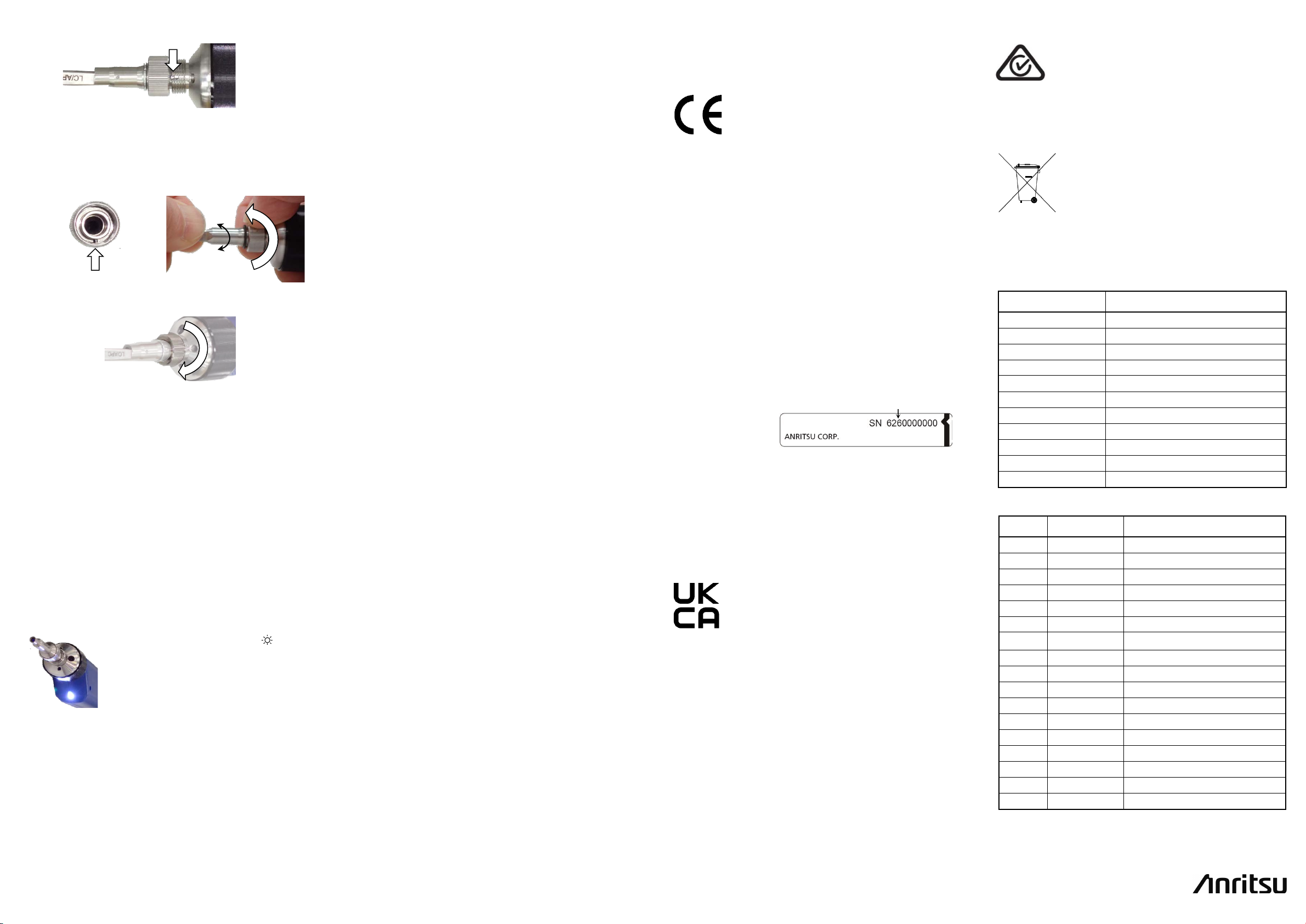
How to Install 60-LC-PC-F, Long-LC-PC-F, and
Long-LC-APC-F
When using the 60-LC-PC-F, Long-LC-PC-F, or Long-LC-APC-F
probe tip, the lensed ferrule adapter is not required, so detach it
before installing the ferrule adapter.
1. Loosen the ring fastening the lensed ferrule adapter by
rotating it in the direction shown in the figure.
2. Remove the lensed ferrule adapter.
3. Plug the ferrule adapter in with its protrusion aligned with
the groove on the probe.
Page 2
Anritsu Corporation
For 60-LC-PC-F or Long-LC-APC-F
Slide the floodlight switch to the side
Anritsu affixes the CE conformity marking on the
and RoHS directive of the European Union (EU).
Anritsu affixes the UKCA marking on the following
Anritsu affixes the RCM mark on the following
Australia/New Zealand.
After this product has served its purpose, it
disposal of Anritsu products for your area.
Interface
USB 2.0 (Compatible USB 1.1 )
Display Resolution
640*480
Resolution
< 1 µm
Field of View
0.365*0.273 µm
Focus Mode
Manual
Operating Voltage
5 ± 0.2 V
Operating Temperature
–10 to +50ºC
Storage Temperature
–40 to +70ºC
Dimensions
33 mm (W) x 44 mm (H) x 211 mm (D)
Mass
260 g
Cable Length
3 m
H0382A
2.5PC-M
2.5 mm PC universal
H0383A
1.25PC-M
1.25 mm PC universal
H0384A
SC-PC-F
For SC connector (PC), bulkhead
H0395A
FC-APC-F
For FC connector (APC), bulkhead
H0386A
FC-PC-F
For FC connector (PC), bulkhead
H0387A
2.5APC-M
2.5 mm APC universal
H0388A
1.25APC-M
1.25 mm APC universal
H0389A
E2000-APC-M
For E2000 connector (APC), universal
H0390A
E2000-PC-F
For E2000 connector (PC), bulkhead
H0391A
E2000-PC-M
For E2000 connector (PC), universal
H0393A
LC-PC-F-L
For LC connector (PC), long bulkhead
H0394A
LC-APC-F-L
For LC connector (APC), long bulkhead
H0385A
LC-PC-F
For LC connector (PC), bulkhead
H0396A
ST-PC-F
For ST connector (PC), bulkhead
H0397A
MU-PC-F
For MU connector (PC), bulkhead
H0398A
SC-APC-F
For SC
connector
(APC), bulkhead
H0403A
60-LC-PC-F
For LC
connector
(PC), bulkhead
Protrusion
Loosen
Tighten
Serial number example
If the third digit of the serial number is "7", the product
complies with Directive 2011/65/EU as amended by
(EU) 2015/863.
(Pb,Cd,Cr6+,Hg,PBB,PBDE,DEHP,BBP,DBP,DIBP)
If the third digit of the serial number is "6", the product
complies with Directive 2011
(Pb,Cd,Cr6+,Hg,PBB,PBDE)
Third digit
a.
■ Warranty Information
Anritsu Corporation provides the following warranty against
stoppages arising due to manufacturing error, and against
problems with operation occurring even though the procedures
outlined in the operation manual were followed.
sales office listed in Anritsu Service and Sales office. Contact
information can be found in a separate file.
■ Compliance Information
CE Conformity Marking:
For Long-LC-PC-F
b.
The protrusion on the Long-LC-PC-F cannot be seen
from outside. Lightly tighten the ring, and then
return it 90° to loosen. While pushing in and rotating
the ferrule adapter, align the protrusion with the
groove on the probe.
4. Fasten the ring by rotating it in the direction shown in the
figure.
Note:
Depending on the angle where the probe tip has attached,
the fiber edge may be out of the image field. Adjust the angle
by monitoring the image.
Power Button
When the power button is pressed, the power lamp lights up.
If the VIP is connected via USB to a battery-powered PC or
measuring instrument, turn off the PC or measuring instrument,
and you can save the battery.
Adjusting the focus
1. Connect the USB connector to the Anritsu product or PC.
2. Start the VIP control application and display the image.
3. Insert the optical connector into the probe tip.
4. Rotate the focus ring while checking the image displayed
by the application.
Floodlight LED
to turn on the floodlight LED.
The floodlight LED can illuminate a dark
place, so you can handle VIP in the dark.
Cleaning
If there is dirt on the lens surface, wipe it with a soft cloth
moistened with alcohol.
Avoid leaving any wiping traces on the lens surface.
Cap
Put the protective cap on the ferrule adaptor when the VIP is not
used.
■ Equipment Certificate
Anritsu Corporation guarantees that this equipment meets the
published specifications.
5 6 7 8
The equipment is warranted for one year from delivery and will
be replaced free of charge under warranty.
After the expiration of one-year warranty period, repairs or
replacement will not be made on the failed equipment. Please
consider purchasing a new one.
The warranty is not valid under any of the following conditions:
The fault is due to mishandling, misuse, or unauthorized
modification or repair of the equipment by the customer.
The fault is due to severe usage clearly exceeding normal
usage.
The fault is due to improper or insufficient maintenance by
the customer.
The fault is due to natural disaster, including fire, wind or
flood, earthquake, lightning strike, or volcanic ash, etc.
The fault is due to damage caused by acts of destruction,
including civil disturbance, riot, or war, etc.
The fault is due to explosion, accident, or breakdown of any
other machinery, facility, or plant, etc.
The fault is due to use of non-specified peripheral or
applied equipment or parts, or consumables, etc.
The fault is due to use of a non-specified power supply or in
a non-specified installation location.
The fault is due to use in unusual environments
The fault is due to activities or ingress of living organisms,
such as insects, spiders, fungus, pollen, or seeds.
In addition, this warranty is valid only for the original
equipment purchaser. It is not transferable if the equipment is
resold.
Anritsu Corporation shall assume no liability for damage or
financial loss of the customer due to the use of or a failure to use
this equipment, unless the damage or loss is caused due to
Anritsu Corporation’s intentional or gross negligence.
Note:
For the purpose of this Warranty, "unusual environments"
means use:
In places of direct sunlight
•
In dusty places
•
Outdoors
•
In liquids, such as water, oil, or organic solvents, and
•
medical fluids, or places where these liquids may adhere
In salty air or in place chemically active gases (sulfur
•
dioxide, hydrogen sulfide, chlorine, ammonia, nitrogen
dioxide, or hydrogen chloride etc.) are present
In places where high-intensity static electric charges or
•
electromagnetic fields are present
In places where abnormal power voltages (high or low) or
•
instantaneous power failures occur
In places where condensation occurs
•
In the presence of lubricating oil mists
•
In places at an altitude of more than 2,000 m
•
In the presence of frequent vibration or mechanical shock,
•
such as in cars, ships, or airplanes
■ Anritsu Corporation Contact
In the event that this equipment malfunctions, please contact a
(Note)
.
following product in accordance with the Decision
768/2008/EC to indicate that it conforms to the EMC
Product Model
Model: G0306C Video Inspection Probe
Applied Directive
EMC: Directive 2014/30/EU
RoHS: Directive 2011/65/EU, (EU) 2015/863
Applied Standards
EMC:
Emission: EN 61326-1: 2013 (Class A)
Immunity: EN 61326-1: 2013 (Table 2)
RoHS: EN IEC 63000:2018 (Category 9)
/65/EU.
Contact
Name: Anritsu GmbH
Address, city: Nemetschek Haus,
Konrad-Zuse-Platz 1
81829 München,
Country: Germany
UKCA Marking:
products in accordance with the guidance to
indicate that they conform to the EMC and RoHS
regulations in the United Kingdom.
Product Model
Model: G0306C Video Inspection Probe
Applied Regulations
EMC: S.I. 2016 No. 1091
RoHS: S.I. 2012 No. 3032
Applied Standards
EMC:
Emission: EN 61326-1: 2013 (Class A)
Immunity: EN 61326-1: 2013 (Table 2)
RoHS: EN IEC 63000:2018 (Category 9)
Contact
Name: ANRITSU EMEA Ltd.
Address, city: 200 Capability Green, Luton
Bedfordshire, LU1 3LU
Country: United Kingdom
RCM Conformity Marking:
product in accordance with the regulation to
indicate it conforms to the EMC framework of
Product Model
Model: G0306C Video Inspection Probe
Recycling:
should be recycled according to local regulations.
In the European Union, the WEEE (Waste
Electronic and Electrical Equipment) Directive
2012/19/EU specifies that electronic waste be
returned to a recycling center for dismantling
and re-use of materials. Please contact your
Anritsu representative for directions as to
■ Specifications
Item Specification
■ Accessories
Model Name Typ e
5-1-1 Onna, Atsugi-shi, Kanagawa,
243-8555, Japan
φ
φ
φ
φ
 Loading...