

Angelantoni Industrie FRL500 V-GL, FRL500 V, FRL260 V-GL, FRL360 V-GL, FRL360 V User Manual
...
p.-1-
Angelantoni Industrie SpA
Biomedical division
OPERATING
INSTRUCTIONS
FOR
REFRIGERATORS
MODELS DESCRI B E D IN THIS MANUA L : FRL180 V
FRL180 V-GL
FRL260 V
FRL260 V-GL
FRL360 V
FRL360 V-GL
FRL500 V
FRL500 V-GL
MN2424 UT FRL (E) rev. C
MARK
$1*(/$1721, ,QGXVWULH
$1*(/$1721, ,QGXVWULH
6S$
printed on 08/03/00
p.-2-
WARNING
The equipment described hereinafter is not provided for in Annex IV of the European ‘Machine Directives’.
The procedure set out in Article 8, paragraph 2, letter A of the CEE Directives 89/392 and 91/368 must be
therefore applied.
Article 8, paragraph 2, letter A of the CEE Directives 89/392 and 91/368 obliges the manufacturer to issue the
necessary documentation required by the Annex of the above directives and to maintain it in the technical files
of Angelantoni Industrie S.p.A, located in loc. Cimacolle, Massa Martana, Perugia (Italy).
IMPORTANT
The boxes marked wi t h the word ‘WARNING:’ contain important information about safety measures.
The boxes marked with the word ‘Note:’ either contain important pieces of advice on operations to be
performed or aim at completing the information contained in the operating instructions.
RELEASE RELEASED CHAPTERS DATE AUTHOR/S C.Q. APPROVED (date and signature)
A Emission 10/06/99 Technical office/pm 10/06/99; PM
B FRL180 models added 17/02/00 Technical office/pm 17/02/00; PM
C Foto added 23/02/00 Technical office/pm 17/02/00; PM
MN2424 UT FRL (E) rev. C
$1*(/$1721, ,QGXVWULH
$1*(/$1721, ,QGXVWULH
6S$
printed on 08/03/00

p.-3-
TABLE OF CONTE NT S
CHAPTER 1
1)
DATA AND FEATURES OF THE EQUIPMENT............................................................................................................5
1.1) MARKING PLATE DATA.........................................................................................................................................5
1.2) TECHNICAL DATA.................................................................................................................................................5
1.2) FUSES...................................................................................................................................................................5
CHAPTER 2
2)
HOW TO USE THE O PERATI NG INSTRUCTIONS......................................................................................................6
2.1) WHOM THE OPERATING INSTRUCTIONS ARE ADDRESSED TO? .....................................................................6
2.2) PURPOSES OF THE OPERATING INSTRUCTIO NS..............................................................................................6
2.3) LIMITATI ONS OF THE OPERATING INSTRUCTIONS ...........................................................................................6
2.4) HOW TO KEEP THE O PERATI NG INSTRUCTIONS ..............................................................................................6
2.5) WARNING........................................................................................................................ ......................................6
CHAPTER 3
3)
HANDLING OF THE EQUIPMENT...................................................................................................... .........................7
3.1) STATE OF THE EQUIPMENT ................................................................................................................................7
3.2) PERSONNEL REQUIREMENTS.............................................................................................................................7
3.3) NECESSARY MEANS FOR HANDLING THE EQUIPMENT ....................................................................................7
3.4) LIFTING INSTRUCTIONS....................................................................................................................................... 7
3.5) LIFTING AND HANDLING OF A NON PAL L ETI SED EQUIPMENT BY MEANS OF A FORK-LIFT TRUCK .............. 7
3.6) INSTRUCTIONS FOR HANDLING..........................................................................................................................7
3.7) FIXING OF THE EQUIPMENT................................................................................................................................ 7
CHAPTER 4
4) LAY-OUT OF THE EQUIPMENT.........................................................................................................................................8
CHAPTER 5
5) LAY-OUT OF THE EQUIPMENT WITH PACKING ..............................................................................................................9
CHAPTER 6
6)
NECESSARY OPERATIONS AND M ATERIALS FOR INSTALLATI ON.......................................................................10
6.1) OPERATING ENVIRONMENT..............................................................................................................................10
6.2) CONNECTION TO THE ELECTRICAL NETWORK...................................................................................................10
CHAPTER 7
7)
POSITIONING AND INSTALLATION..........................................................................................................................11
7.1) RECEPTION OF THE EQUIPMENT.....................................................................................................................11
7.2) SUPPLY AND GROUND CONNECTIONS................................................................................................................11
7.2.1) SUPPLY CABLE..............................................................................................................................................11
7.2.2) GROUND CONNECTION...........................................................................................................................11
CHAPTER 8
8)
HOW TO USE THE O PERATI NG INSTRUCTIONS....................................................................................................12
8.1) WHOM THE OPERATING INSTRUCTIONS ARE ADDRESSED TO? ...................................................................12
8.2) USER...................................................................................................................................................................12
CHAPTER 9
9)
TECHNICAL DESCRIPTION OF THE EQUI PM ENT ...................................................................................................12
9.1) STRUCTURAL DESCRIPTION .............................................................................................................................12
9.2) COOLING SYSTEM .............................................................................................................................................13
9.3) FUNCTIONING OF THE EL ECTRIC SYSTEM..........................................................................................................13
MN2424 UT FRL (E) rev. C
$1*(/$1721, ,QGXVWULH
$1*(/$1721, ,QGXVWULH
6S$
printed on 08/03/00

p.-4-
CHAPTER 10
10) START-UP AND OPERATIO N INSTRUCTIONS.........................................................................................................13
10.1) DESCRIPTION OF THE COMMAND AND CONTROL PANEL................................................................................13
10.1.1) CONTROL PANEL COMMANDS................................................................................................................13
10.2) EXAM PLE OF START-UP. .....................................................................................................................................14
10.2.1) ELECTRICAL CONNECTION.........................................................................................................................14
10.2.2) EQUIPMENT ON-OFF...................................................................................................................................14
10.2.3) TEMPERATURE SETTING. ...........................................................................................................................14
10.2.4) AL ARM SYSTEM. ..........................................................................................................................................14
10.2.4.1) Alarm system descr iption. ......................................................................................................................14
Alarm system functions description. ......................................................................................................................15
Conditions alarm warnings description. .................................................................................................................15
Further information. ..............................................................................................................................................15
10.2.5) Alarm system t em per at ure threshold alarm regulation...............................................................................15
10.3) SOME PRECAUTIONS...........................................................................................................................................15
10.3.1) INTRODUCTION OF SPECIMENS.............................................................................................................15
10.4) TEMPERATURE CHART RECORDER...................................................................................................................16
10.4.1) USE OF THE RECORDER.............................................................................................................................16
Battery clock.........................................................................................................................................................16
Battery substitution..........................................................................................................................................16
Chart disk replacement....................................................................................................................................16
Spring tightened clock................................................................................................................................ ...........16
Spring tighten..................................................................................................................................................16
Chart disk replacement....................................................................................................................................16
WRITING..............................................................................................................................................................16
Writing cartridges. ...........................................................................................................................................16
11) SERVICING INSTRUCTIONS.........................................................................................................................................17
11.1)
11.2)
11.3)
12) PROBLEMS AND TROUBLESHOOTING...................................................................................................................18
13) DEMOLITION OF THE EQUIPMENT.........................................................................................................................19
13.1)
14) REFRIGERATING DIAGRAM.........................................................................................................................................20
15) WIRING DIAGRAM.........................................................................................................................................................21
16) HANDLE MOUNTING.....................................................................................................................................................22
Writing cartridges replacement . ....................................................................................................................... 16
CHAPTER 11
STRUCTURE CLEAN-UP................................................................................................................................17
11.1.1) CLEANING OF GASKETS..........................................................................................................................17
11.1.2) AIR CONDENSER CLEAN-UP...................................................................................................................17
COOLING SYSTEM........................................................................................................................................17
ELECTRIC - ELECTRONIC PART...................................................................................................................17
CHAPTER 12
CHAPTER 13
TYPES OF MATERIAL IN THE EQUIPMENT ..................................................................................................19
CHAPTER 14
CHAPTER 15
CHAPTER 16
MN2424 UT FRL (E) rev. C
$1*(/$1721, ,QGXVWULH
$1*(/$1721, ,QGXVWULH
6S$
printed on 08/03/00
p.-5-
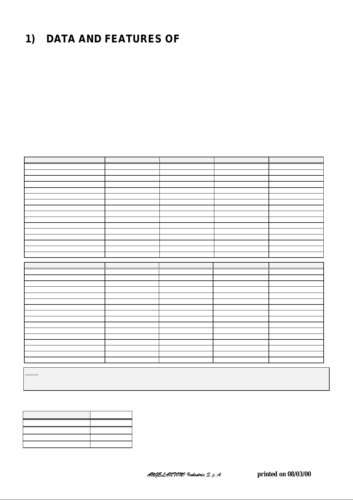
1) DATA AND FEATURES OF THE EQUIPMENT
1.1) MARKING PLATE DATA
ANGELANTONI Industrie SpA Tel. +39.75-8955.1
località Cimacolle Fax +39.75-8955.200
06056 Massa Martana (Perugia)
Italy
Model : FRL ………………………………………
Serial Number : No. ..............................................................
Test : No. ..............................................................
Year of production : 2000
Marking : CE
1.2) TECHNICAL DATA
Models FRL180 V FRL260 V FRL360 V FRL500 V
Useful capacity (l) 180 260 360 500
Temperature r ange da + 2 °C a + 12 °C da + 2 °C a + 12 °C da + 2 °C a + 12 °C da + 2 °C a + 12 °C
Temperature + 4 °C + 4 °C + 4 °C + 4 °C
Precision (± °C) without internal load
Supp ly. 230V +6/-10% 50Hz ; 1+G 230V +6/-10% 50Hz ; 1+G 230V +6/-10% 50Hz ; 1+G 230V +6/-10% 50Hz ; 1+G
Ratin g absorb. curren t. 0,5 A 0,6 A 0,65 A 0,65 A
Medium power. 0,12 kW 0,14 kW 0,15 kW 0,15 kW
Max power 0,15 kW 0,17 kW 0,18 kW 0,18 kW
Energy consumption 1,20 kWh/24h 1,40 kWh/24h 1,60 kWh/24h 1,70 kWh/24h
Heat d issi pation 130 kcal/h 130 kcal/h 130 kcal/h 130 kcal/h
Refrigerating gas R134a R134a R134a R134a
External dimensio ns (WxDxH). 602 x 600 x 1050 mm 602 x 600 x 1385 mm 602 x 600 x 1759 mm 755 x 715 x 1685 mm
Useful exte rnal di mensions (WxD xH). 513 x 433 x 734 mm 513 x 433 x 1047 mm 513 x 433 x 1418 mm 646 x 566 x 1338 mm
Over all weight with standard packing 47 kg 57 kg 67 kg 78 kg
Over all we ight without pac king 44 kg 54 kg 64 kg 75 kg
Max. noise level 55 dB (A) 58 dB (A) 58 dB (A) 58 dB (A)
Models FRL 180 V-GL FRL260 V - GL FRL360 V - GL FRL500 V-GL
Useful capacity (l) 180 260 360 500
Temperature r ange da + 2 °C a + 12 °C da + 2 °C a + 12 °C da + 2 °C a + 12 °C da + 2 °C a + 12 °C
Temperature + 4 °C + 4 °C + 4 °C + 4 °C
Precision (± °C) without internal load
Supp ly. 230V +6/-10% 50Hz; 1+G 230V +6/-10% 50Hz; 1+G 230V +6/-10% 50Hz ; 1+G 230V +6/-10% 50Hz ; 1+G
Ratin g absorb. curren t. 0,6 A 0,65 A 0,8 A 0,8 A
Med ium po wer. 0,14 kW 0,15 kW 0,18 kW 0,18 kW
Max p ower. 0,17 kW 0,18 kW 0,21 kW 0,21 kW
Ene r gy consumptio n 1,80 kWh/24h 1,90 kWh/24h 2,10 kWh/24h 2,30 kWh/24h
Heat d issipatio n 170 kcal/h 170 kcal/h 170 kcal/h 170 kcal/h
Refrigerating gas R134a R134a R134a R134a
External dimensio ns (WxDxH). 602 x 600 x 1050 mm 602 x 600 x 1385 mm 602 x 600 x 1759 mm 755 x 715 x 1685 mm
Useful exte rnal di mension s (WxD xH). 513 x 433 x 734 mm 513 x 433 x 1047 mm 513 x 433 x 1418 mm 646 x 566 x 1338 mm
Over all we ight with stand a rd pac king 57 kg 68 kg 83 kg 98 kg
Over all we ight without pac king 54 kg 65 kg 80 kg 95 kg
Max. noise level 55 dB (A) 58 dB (A) 58 dB (A) 58 dB (A)
Note: The standard packaging is made of cartboard or plastic for transport by road and/or by plane. In case of shipping
transport, please conta ct t he ANGELANTONI Industr i e spa shipp i ng department to know dimen si on s and weigh t s of the
packed equipment.
2 °C 2 °C 2 °C 2 °C
2 °C 2 °C 2 °C 2 °C
1.2) FUSES.
Models Value/code
6 A / F
FRL180 V, FRL180 V-GL
FRL260 V, FRL260 V-GL
FRL360 V, FRL360 V-GL
FRL500 V, FRL500 V-GL
MN2424 UT FRL (E) rev. C
6 A / F
6 A / F
6 A / F
$1*(/$1721, ,QGXVWULH
$1*(/$1721, ,QGXVWULH
6S$
printed on 08/03/00

p.-6-
2) HOW TO USE THE OPERATING INSTRUCTIONS
This chapter describes how to use the operating instructions and their limitations.
2.1) WHOM THE OPERATI N G INSTRUCTIONS ARE ADDRESSED TO?
This guide is addressed to people in charge of:
- tr ansport, loading and unloading, stocking;
- use of the equipment;
- installation;
- servicing.
2.2) PURPOSES OF THE OPERATING INSTRUCT IONS
This guide provides information on the intended use, technical features, instructions for the handling, installation, tuning and
use of the equipment. It also contains useful addresses where to send any intervention request or any order for materials of
consumption (for spare parts please refer to the service manual or contact Angelantoni’s technical assistance service).
2.3) LIMITATIONS OF THE OPERATING INSTRUCTIONS
Please remember that the operating instructions (hereinafter referred to as
user and must be ther e fore t aken as a re fe rence book for the main operations to be performed. Moreover, it should be noted
that the O.I. describe the techniques used at the moment of the equipment’s purchase; the manufacturer reserves the right to
make all necessary update to the O.I. and products without obligation to replacement of previous ones., particular cases
excepted.
) cannot replace an adequate knowledge by the
O.I.
2.4) HOW TO KEEP THE OPERATING INSTRUCT IONS
The user must keep the O.I. very carefully in order to make them available throughout the equipment’s lifetime. For this
purpose, the O.I. are supplied in a special bag usually placed on the right side of the equipment, aimed at protecting them
against wear-and-t ear . Should the O.I. be destroyed or lost, ask for a supplementary copy to your local agent or to the
manufacturer directly, specifying the type, model, year of production of the equipment.
2.5) WARNING
WARNING:
Never perform any operation or movement if you cannot foresee their effects; in case of doubts, please contact the
manufacturer or your local agent. The manufacturer cannot be held responsible for damages caused to the equipment,
things or persons in case of:
- improper use of the equipment by non authorised personnel;
- incorrect installation;
- improper supply;
- failure to comply with compulsory servicing operations;
- unauthorised modifications or interventions;
- use of spare parts other than original or specific ones for the type of equipment;
- total or partial failure to comply with the instructions;
- exceptional events.
Note
The temp erature set value is not displayed for th at reason to contro l the temperature please see the
digital thermometer after a period of 10 minutes of operating of the system.
MN2424 UT FRL (E) rev. C
$1*(/$1721, ,QGXVWULH
$1*(/$1721, ,QGXVWULH
6S$
printed on 08/03/00

p.-7-
3) HANDLING OF THE EQUIPMENT
This chapter contains the necessary instructions to load, unload and handle the equipment properly.
3.1) STATE OF THE EQUIPMENT
The equipment is usually delivered inside a special palletised packing. In case of direct consignment by Angelantoni’s
authorised personnel, the equipment may have no packing.
3.2) PERSONNEL REQUIREMENTS
No particular requirement is needed to handle the equipment (please take into account the type of packing). In any case, it is
advisable to let these operations be performed by people acquainted with the use of lifting and transport means.
3.3) NECESSARY MEANS FOR HANDLING THE EQUIPMENT
The equipment can be lifted and handled by means of lifting trucks or any other suitable means whose min. loading capacity
equals the weight declared in the technical data sheet (ref. 1.2).
WARNING:
Although handling operations are quite easy, it is advisable to check the correct balance of the load.
3.4) LIFTING INSTRUCTIONS.
All new equipment are shipped packed inside special pallets.
The overall weight of equipment and packing is easily readable also from the outside of the packing.
Pallets allow easy slinging for lifting by bridge cranes or by fork-lift trucks.
WARNING:
Although handling operations are quite easy, it is advisable to check the correct balance of the load.
3.5) LIFTING AND HANDLING OF A NON PALLETISED EQUIPMENT BY
MEANS OF A FORK-LIFT TRUCK
It is strongly recommended to insert the forks of the fork-lift truck correctly in order to avoid the equipment to be damaged.
WARNING:
Make sure that the forks of the fork-lift truck do not come directly into contact with the external panels of the
equipment as they could damage it.
Never use fork-lift trucks or similar machines on equipment without pallets.
3.6) INSTRUCTIONS FOR HANDLING
The equipment being supported by four feet (no wheels), it is therefore not possible to move it manually.
No particular precaution is needed if the floor in the working area is well levelled.
WARNING:
Handle the equipment with suitable means only (fork-lift trucks, etc.).
In case of accidental bumps, please check if there is any damage and, should it be necessary, contact the manufacturer.
In order to avoid that the oil contained into the compressor flows into the cooling circuit, the equipment must be
transported, st ocked and handle d i n vertical position only, by carefully observing the indicati ons on the pac king:
should the equipment be necessarily turned over, please contact Angelantoni’s local agent or the manufacturer
directly.
The special wooden base features slots for the introduction of the forks of the fork-lift truck and allows the easy
handling and l i f t i ng of the e quipment with conventional means.
3.7) FIXING OF THE EQUIPMENT
The equipment has been conceived to be operated on horizontal planes.
Under these conditions, no blocking device is needed.
MN2424 UT FRL (E) rev. C
$1*(/$1721, ,QGXVWULH
$1*(/$1721, ,QGXVWULH
6S$
printed on 08/03/00
 Loading...