

Angelantoni Industrie CHALLENGE - ES, CHALLENGE - E, CHALLENGE Service manual
SERIES
CHALLENGE
CHALLENGE - E
CHALLENGE - ES
THERMOSTATIC AND CLIMATIC CHAMBERS
ecology project
Installation, use and maintenance handbook
Angelantoni Industrie S.p.A.
06056 Massa Martana (Pg) Italy
Tel. (++39) 075.8955.1 (a.r.)
Fax (++39) 075.8955200
Internet: www.angelantoni.it
E-Mail:info@angelantoni.it
CHF6053
Cod. 512974 - Rel. 140303


464 Località Cimacolle
06056 Massa Martana (Pg) Italy
DICHIARAZIONE DI CONFORMITÀ
DECLARATION OF CONFORMITY
Denominazione prodotto
Product Name
Costruttore
Manufacturer
La macchina è conforme ai dettami delle seguenti Direttive
CEE:
• Direttiva Macchine n° 98/37, successive modifiche e
DPR 459/96.
• Direttiva Bassa Tensione n° 73/23 e successive modifiche.
• Direttiva Compatibilità Elettromagnetica n° 89/336 e
successive modifiche.
In particolare soddisfa le seguenti Norme Armonizzate:
CHALLENGE
Ordine / Serie N.
Order/series N
Mandatario
Agent
The machine complies with the regulations in the following
EEC Directives:
• Machinery Directive n° 98/37, subsequent modifications and DPR 459/96.
• Low Voltage Directive n° 73/23 and subsequent modifications.
• Electromagnetic Compatibility Directive n° 89/336 and
subsequent modifications.
I
n particular it complies with the following Standardized
Norms:
°
• EN 292-1 Sicurezza del macchinario - Concetti fondamentali, principi generali di progettazione - Parte 1:
Terminologia, metodologia di base. 1991.
• EN 292-2 Sicurezza del macchinario - Concetti fondamentali, principi generali di progettazione - Parte 2:
Specifiche e principi tecnici. 1991.
• EN 294 Sicurezza del macchinario - Distanza di sicurezza per impedire il raggiungimento di zone pericolose
con gli arti superiori. 1992
• EN 61326-1 Apparecchi elettrici di misura, controllo e
laboratori. Prescrizioni di compatibilità elettromagnetica. - Parte 1: Prescrizioni generali e successive modifiche.
• EN 61010-1 Prescrizioni di sicurezza per apparecchi
elettrici di misura, controllo e per utilizzo in laboratorio Parte 1: Prescrizioni generali.
Data
Date
• EN292-1 Safety of machinery - Fundamental concepts,
general principles for design - Part 1: Terminology,
basic methodology, 1991.
• EN292-2 Safety of machinery - Fundamental concepts,
general principles for design - Part 2: Technical specifications and principles. 1991.
• EN294 Safety of machinery - Safety distance to prevent
upper limbs coming into contact with dangerous areas.
1992.
• EN61326-1 - Electrical equipment for measurement,
control and laboratory use EMC requirements - Part. 1
- General requirements.
• EN61010-1 Safety instructions for electrical apparatus
to measure, and control and for laboratory use - Part 1:
General instructions.
L’amministratore delegato
Managing Director
Gianluigi Angelantoni

CONTENTS
1 SUMMARY OF RATING PLATE DATA ......................................................................................................................................................... 5
2 WARNINGS ................................................................................................................................................................................................ 5
2.1 GENERAL WARNINGS ......................................................................................................................................................................... 5
2.2 WARNINGS FOR TRANSPORT AND HANDLING ................................................................................................................................ 6
2.3 WARNINGS FOR INSTALLATION ......................................................................................................................................................... 6
2.4 WARNINGS FOR PERSONNEL IN CHARGE OF THE MACHINE ....................................................................................................... 6
2.5 WARNINGS FOR MAINTENANCE........................................................................................................................................................ 6
2.6 EXPLANATION OF SYMBOLS .............................................................................................................................................................. 6
3 TECHNICAL SPECIFICATIONS ................................................................................................................................................................... 7
3.1 TECHNICAL DATA FOR CLIMATIC CHAMBERS.................................................................................................................................. 7
3.2 TECHNICAL DATA FOR THERMOSTATIC CHAMBERS....................................................................................................................... 12
3.3 PERFORMANCE -gradients .................................................................................................................................................................. 16
3.4 ENVIRONMENTAL CONDITIONS ......................................................................................................................................................... 17
3.5 FUSES ................................................................................................................................................................................................ 18
4 HANDLING AND REMOVAL OF PACKAGING ............................................................................................................................................ 19
4.1 PERSONNEL REQUISITES .................................................................................................................................................................. 19
4.2 MACHINE CONDITIONS....................................................................................................................................................................... 19
4.3 EQUIPMENT NEEDED FOR HANDLING ............................................................................................................................................. 19
4.4 HOW TO REMOVE THE PACKAGING .................................................................................................................................................. 20
4.4.1 How to remove the outer straps................................................................................................................................................... 20
4.4.2 How to remove the cardboard casing .......................................................................................................................................... 20
4.4.3 How to remove the internal straps ............................................................................................................................................... 20
4.4.4 How to remove the wooden side blocks....................................................................................................................................... 20
5 DESCRIPTION OF THE SYSTEM ................................................................................................................................................................ 21
6 INSTALLATION ............................................................................................................................................................................................. 26
7 USE FORESEEN BY THE MANUFACTURER.............................................................................................................................................. 33
8 START-UP ................................................................................................................................................................................................ 34
9 USE ................................................................................................................................................................................................ 37
10 SAFETY DEVICES -CHECK AND SET-UP .................................................................................................................................................. 43
11 MAINTENANCE ............................................................................................................................................................................................ 44
12 TROUBLESHOOTING .................................................................................................................................................................................. 48
13 REMOVAL FROM INSTALLATION SITE ...................................................................................................................................................... 50
4.4.5 How to remove the pallet ............................................................................................................................................................. 20
5.1 GENERAL VIEW.................................................................................................................................................................................... 21
5.2 CONTROL SYSTEM.............................................................................................................................................................................. 23
5.3 COOLING SYSTEM............................................................................................................................................................................... 24
5.4 DEHUMIDIFCATION SYSTEM .............................................................................................................................................................. 24
5.5 HUMIDIFICATION SYSTEM .................................................................................................................................................................. 25
5.6 HEATING SYSTEM ................................................................................................................................................................................ 25
5.7 INTERNAL LIGHT.................................................................................................................................................................................. 25
5.8 PROBES ................................................................................................................................................................................................ 25
6.1 POSITIONING OF THE MACHINE ........................................................................................................................................................ 26
6.2 PLUMBING ............................................................................................................................................................................................ 27
6.2.1 Condensate drain ........................................................................................................................................................................ 27
6.2.2 Mains water or demineralized water supply for humidification ..................................................................................................... 27
6.2.3 Water supply for condenser......................................................................................................................................................... 28
6.3 ELECTRICAL WIRING........................................................................................................................................................................... 29
6.3.1 Characteristics of the plug ........................................................................................................................................................... 29
6.3.2 Socket Board ............................................................................................................................................................................... 29
6.3.3 General specifications for the electrical system........................................................................................................................... 29
6.3.4 Electrical wiring ............................................................................................................................................................................ 29
6.3.5 Earth connection .......................................................................................................................................................................... 29
6.3.6 Preferential supply for the internal computer ............................................................................................................................... 30
6.3.7 Lamp connection for irradiation and UV radiations...................................................................................................................... 30
6.3.8 Specimen power supply connection ............................................................................................................................................ 30
6.3.9 Interface and serial port connection............................................................................................................................................. 30
7.1 AIM OF THE MACHINE ......................................................................................................................................................................... 33
7.2 MACHINE END-USE ............................................................................................................................................................................. 33
7.3 OPERATOR ........................................................................................................................................................................................... 33
7.4 USE LIMITS ........................................................................................................................................................................................... 33
7.5 USE OF PROTECTIVE CLOTHING ...................................................................................................................................................... 33
7.6 DANGEROUS AREAS AND WASTE RISKS ......................................................................................................................................... 33
8.1 COMPRESSOR OIL HEATING.............................................................................................................................................................. 34
8.2 ALARM SET-UP ..................................................................................................................................................................................... 34
8.2.1 Software alarms ........................................................................................................................................................................... 35
8.2.2 Hardware alarms ......................................................................................................................................................................... 35
8.2.3 Fixed alarm for maximum temperature ........................................................................................................................................ 36
8.3 OPERATIONAL CHECK ........................................................................................................................................................................ 36
8.4 CONTROL OF WET BULB GAUZE (climatic chambers) ....................................................................................................................... 36
9.1 LOADING OF THE PRODUCT TO BE TESTED.................................................................................................................................... 37
9.2 POSITIONING OF CONTROL PANEL................................................................................................................................................... 39
9.2.1 Panel inclined upwards .............................................................................................................................................................. 39
9.2.2 Panel inclined downwards.......................................................................................................................................................... 39
9.2 SET-UP FOR A TEMPERATURE CYCLE.............................................................................................................................................. 40
9.3 UV LAMP (optional) ............................................................................................................................................................................... 41
9.4 SHUTDOWN.......................................................................................................................................................................................... 42
9.5 EMERGENCY SHUTDOWN.................................................................................................................................................................. 42
9.6 START-UP AFTER AN EMERGENCY SHUTDOWN ............................................................................................................................. 42
13.1DISASSEMBLY ...................................................................................................................................................................................... 50
13.2SCRAPPING.......................................................................................................................................................................................... 50
4
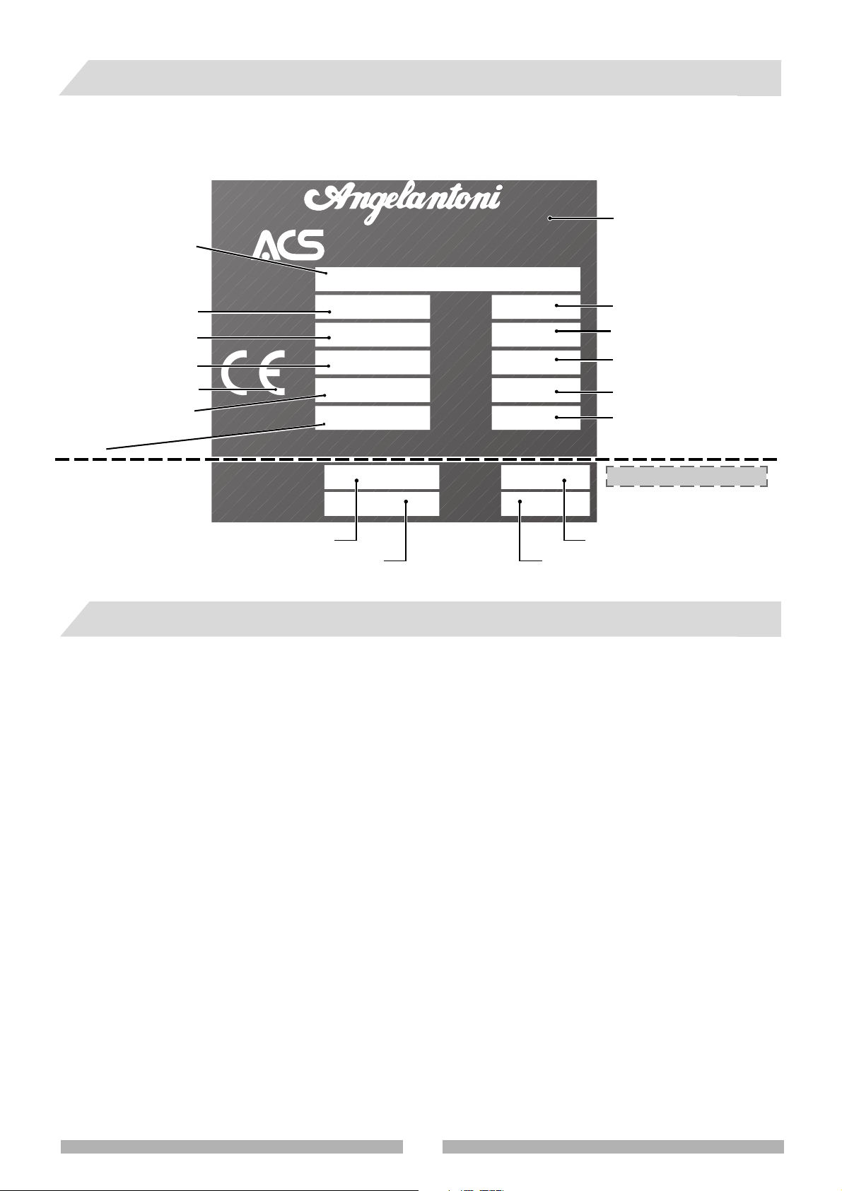
1 SUMMARY OF RATING PLATE DATA
• Find the special rating plate on the machine in order to check the technical data.
• Check the machine model and supply voltage before carrying out any operation whatsoever.
• If you find any discrepancies, contact the manufacturer or your supplier immediately.
Model
Series N°
Min-max temperature
Supply voltage
EC compliance symbol
Maximum electrical
absorption
Weight
2 WARNINGS
Type
Serial No.
°C
V
A
Weight kg
Gas 1
Gas
properties
Gas 2
Type of cooling gas 1
Type of cooling gas 2
Industrie S.p.A.
environmental chamber division
massa martana (pg) Italy
Year
%
kW
HP
Gas
Bar
Bar
Pressure of cooling gas 2
Manufacturer’s address
Year of manufacture
Min-max relative humidity
Absorbed power
Compressor power
Type of cooling gas
Only for some countriers
Pressure of cooling gas 1
2.1 GENERAL WARNINGS
• Do not carry out any operations or manoeuvres unless you are absolutely certain of their effect; if in doubt, contact
your nearest technical assistance service or the manufacturer himself.
• The manufacturer will not be held responsible for damage to the machine or to objects in the following cases:
- improper use of the machine
- use of unsuitable personnel
- incorrect assembly and installation
- defects in the plant systems
- unauthorized modifications or operations to the machine
- use of spare parts that are not original pieces
- failure to comply with the norms given in this handbook
- exceptional events
• This instruction handbook has been designed for the following personnel:
- Personnel in charge of transport, handling and removal of packaging
- Personnel in charge of the preparation of the plant systems and installation site
- Installers
- Personnel in charge of using the machine
- Personnel in charge of maintenance
• The instruction handbook indicates the use foreseen by the manufacturer and cannot ever replace adequate
experience of the operator. It can only be used as a reminder of the main operations to be carried out.
• The instruction handbook should be kept carefully and should also be within easy reach for reference. If necessary,
photocopy the pages concerned directly with machine use. The handbook should last at least the life-time of the
machine itself.
5
• The instruction handbook gives technical information on how the machine is manufactured at the present time; the
manufacturer reserves the right to carry out any modifications he deems necessary to the machines and to the
instruction handbooks, without prior notice or replacement.
This handbook should last at least as long as the machine itself.
It is, therefore, a good idea to protect it against damages.
If you lose or destroy the handbook, you may ask for a copy. Please give the rating plate data (see chap. 1) in your
request.
2.2 WARNINGS FOR TRANSPORT AND HANDLING
• This symbol, placed on each packaging, indicates the weight of each package.
• Always check that the tools and machines to handle and transport the machine are adequate.
121199 mod
• Always keep the machine in an upright position. If the machine should accidentally turn upside-down or
on its side, do not switch it on. Put it in the correct position and contact the manufacturer.
2.3 WARNINGS FOR INSTALLATION
• Installation should always be carried out by specialized personnel.
• Carefully follow the instructions on how to prepare the plant systems before installing the machine.
• When the installation site is being prepared, bear in mind the space and work conditions of the personnel in charge
of the machine so as to reduce to a minimum noise, fatigue, discomfort and anything else which may have a negative
influence on the staff.
• When designing the installation site, remember to leave sufficient space for control, maintenance, cleaning, and
removal of production waste material.
• Make sure there are clear notices near the machine to warn personnel who are not in charge of the dangers withing
the work range of the machine during the work cycle.
• Make sure that the work site is adequately lit so that personnel can work in optimum conditions.
• When designing the installation site, please refer to the norms in force and in particular:
- set up all the firefighting and safety devices.
2.4 WARNINGS FOR PERSONNEL IN CHARGE OF THE MACHINE
•
After a pause of over 48 hours in the work cycle, always heat the compressor
oil before carrying out any work (see paragraph 8.1).
• The machine may only be used by personnel who have read the rules
described in this handbook.
• If the chamber is opened in temperatures that differ greatly from ambient
temperatures, problems could be created: if the internal temperature is
high, it will be very difficult to close the door because of expansion; if the
internal temperature is very low, phenomena of condensate and frosting
Very important!
In order to guarantee the
standard of safety for the
products to be tested and for
the machine, always set the
software and hardware
temperature
alarms (paragraph 8.2).
due to ambient humidity could occur. If the door is opened frequently in
these conditions, it is not only dangerous but could cause damage to the gaskets of the door and could obstruct the
heat exchangers.
2.5 WARNINGS FOR MAINTENANCE
• Always disconnect the machine from the hydraulic and electrical mains supply before carrying out any maintenance
operation whatsoever.
• Always close all the stop valves above the machine.
• Do not use solvents or alcohol to clean the varnished parts as these products could damage the surface.
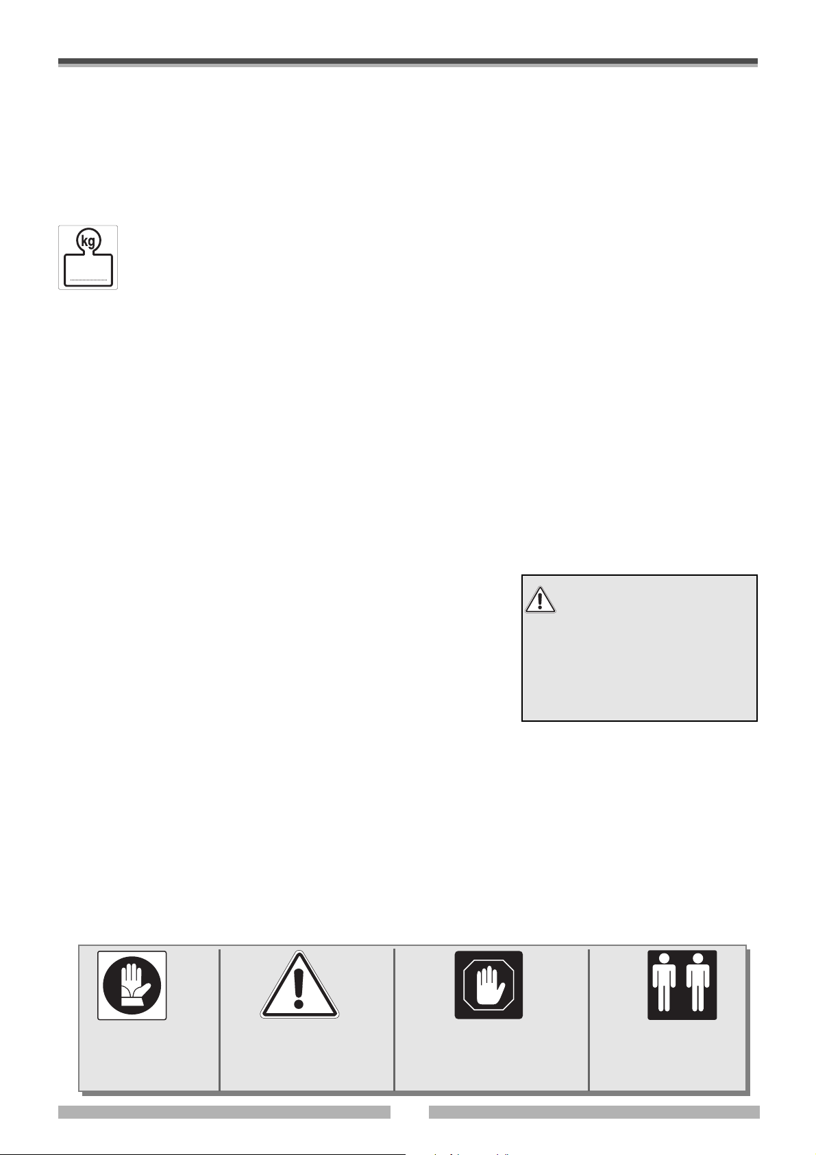
2.6 EXPLANATION OF SYMBOLS
• The symbols shown below may be found on the machine or in this instruction handbook.
• Pay attention to their meaning before going any further.
USE GLOVES
GENERAL DANGER
This symbol is always
accompanied by an
explanation of the danger
WARNING!
Important note
Operations that must be
carried out by at least
two people.
6

3 TECHNICAL SPECIFICATIONS
3.1 TECHNICAL DATA FOR CLIMATIC CHAMBERS
The climatic chambers carry out tests by controlling temperature and relative humidity
C
HALLENGE SERIE MOD
.
CH250 CH340 CH600 CH1200 CH1600 CH2000
Useful volume (l)
Temperature range (°C)
Accuracy (± °C)
Humidity range (with temperature
from +5 to +95°C)
RH accuracy (no less than +/-0,25°C
on psychometric difference)
Dew point range for continuous
tests (°C)
Dew point range for discontinuous
tests (°C)
Supply voltage
Max electrical absorption
Rated output
Max. used power
Maximum internal
temperature load (W)
Cooling gas
(3)
(3)
(V)
(kW)
(3)
(kW)
(3)
(A)
224
-40 +180
0,25 ÷ 0,3
10 ÷ 98%
1% ÷ 3%
+2
+94 °C
-20
+2°C
400 +6/-10%
50Hz 3+N+G
14
4,8
7,7
400
(-25 °C)
R404 A
336
-40 +180
0,25 ÷ 0,3
10 ÷ 98%
1% ÷ 3%
+2
+94 °C
-20
+2°C
400 +6/-10%
50Hz 3+N+G
14
4,8
7,7
400
(-25 °C)
R404 A
557
-40 +180
0,25 ÷ 0,3
10 ÷ 98%
1% ÷ 3%
+2
+94 °C
-20
+2°C
400 +6/-10%
50Hz 3+N+G
20,5
6,8
11,4
1000
(-25 °C)
R404 A
1152
-40 +180
0,25 ÷ 0,3
10 ÷ 98%
1% ÷ 3%
+2
+94 °C
-20
+2°C
400 +6/-10%
50Hz 3+N+G
26,3
8,7
14,6
1300
(-25 °C)
R404 A
1535
-40 +180
0,25 ÷ 0,3
10 ÷ 98%
1% ÷ 3%
+2
+94 °C
-20
+2°C
400 +6/-10%
50Hz 3+N+G
26,3
8,7
14,6
1300
(-25 °C)
R404 A
2040
-40 +180
0,25 ÷ 0,3
10 ÷ 98%
1% ÷ 3%
+2
+94 °C
-20
+2°C
400 +6/-10%
50Hz 3+N+G
26,3
8,7
14,6
500
(-25 °C)
R404 A
External dimensions (LxDxH) without
wheels (with wheels
Useful internal dimensions (LxDxH) (mm)
Maximum weight to be loaded on
each internal shelf (kg)
Overall weight with standard
packaging (1) (kg)
Overall weight without packaging (kg)
Floor load (kg/m2)
Noise level with air condenser (dB A)
Air condenser
Water condenser
(1) Standard packaging is made of cardboard or plastic, suitable for transport by road or air freight.
For sea freight please contact the manufacturer or his agent to request all the relevant information.
(2) Under request when purchasing
(3) In case of special power supply please see enclosed manual.
H tot = H+ h1 ) (mm)
850x1460 x1516
(h1 = 47)
600x535x700
50
530
490
400
59
x
(2)
850x1725x1516
(h1 = 47)
600x800x700
50
600
550
375
59
x
(2)
1100x1705x1911
(h1 = 58)
850x733x895
50
800
750
400
64
x
(2)
1250x2160x2036
(h1 = 58)
1000x1130 x1020
50
1060
990
367
65
x
(2)
1250x2534x2040
(h1 = 70)
1000x1505x1020
50
1370
1300
410
65
x
(2)
1250x3035x2040
(h1 = 70)
1000x2000x1020
50
1470
1400
369
65
x
(2)
7

C
HALLENGE SERIE MOD
.
CH250 C CH340 C CH600 C CH1200 C CH1600 C CH2000 C
Useful volume (l)
Temperature range (°C)
Accuracy (± °C)
Humidity range (with temperature
from +5 to +95°C)
RH accuracy (no less than +/-0,25°C
on psychometric difference)
Dew point range for continuous
tests (°C)
Dew point range for discontinuous
tests (°C)
Supply voltage
Max electrical absorption
Rated output
Max. used power
Maximum internal
temperature load (W)
(3)
(3)
(V)
(kW)
(3)
(kW)
(3)
(A)
224
-75 +180
0,25 ÷ 0,3
10 ÷ 98%
1% ÷ 3%
+2
+94 °C
-20
+2°C
400 +6/-10%
50Hz 3+N+G
16,5
5,7
9
600
(-55 °C)
336
-75 +180
0,25 ÷ 0,3
10 ÷ 98%
1% ÷ 3%
+2
+94 °C
-20
+2°C
400 +6/-10%
50Hz 3+N+G
16,5
5,7
9
500
(-55 °C)
557
-75 +180
0,25 ÷ 0,3
10 ÷ 98%
1% ÷ 3%
+2
+94 °C
-20
+2°C
400 +6/-10%
50Hz 3+N+G
25,9
8,6
14,4
1200
(-55 °C)
1152
-75 +180
0,25 ÷ 0,3
10 ÷ 98%
1% ÷ 3%
+2
+94 °C
-20
+2°C
400 +6/-10%
50Hz 3+N+G
32,3
10,7
17,9
1500
(-55 °C)
1535
-75 +180
0,25 ÷ 0,3
10 ÷ 98%
1% ÷ 3%
+2
+94 °C
-20
+2°C
400 +6/-10%
50Hz 3+N+G
32,3
10,7
17,9
1500
(-55 °C)
2040
-75 +180
0,25 ÷ 0,3
10 ÷ 98%
1% ÷ 3%
+2
+94 °C
-20
+2°C
400 +6/-10%
50Hz 3+N+G
32,3
10,7
17,9
550
(-55 °C)
Cooling gas
External dimensions (LxDxH) without
wheels (with wheels
Useful internal dimensions (LxDxH) (mm)
Maximum weight to be loaded on
each internal shelf (kg)
Overall weight with standard
packaging (1) (kg)
Overall weight without packaging (kg)
Floor load (kg/m2)
Noise level with air condenser (dB A)
Air condenser
Water condenser
(1) Standard packaging is made of cardboard or plastic, suitable for transport by road or air freight.
For sea freight please contact the manufacturer or his agent to request all the relevant information.
(2) Under request when purchasing
(3) In case of special power supply please see enclosed manual.
H tot = H+ h1 ) (mm)
R404 A/R23
850x1460 x1516
(h1 = 47)
600x535 x700
50
580
540
435
63
x
(2)
R404 A/R23
850x1725x1516
(h1 = 47)
600x800x700
50
650
600
410
63
x
(2)
R404 A/R23
1100x1705x1911
(h1 = 58)
850x733x895
50
880
830
445
66
x
(2)
R404 A/R23
1250x2160x2036
(h1 = 58)
1000x1130x1020
50
1160
1090
405
68
x
(2)
R404 A/R23
1250x2534x2040
(h1 = 70)
1000x1505x1020
50
1470
1400
441
68
x
(2)
R404 A/R23
1250x3035x2040
(h1 = 70)
1000x2000x1020
50
1570
1500
395
68
x
(2)
8

C
HALLENGE
ES S
ERIE MOD
.
CH250 ES CH340 ES CH600 ES CH1200 ES CH1600 ES CH2000 ES
Useful volume (l)
Temperature range (°C)
Accuracy (± °C)
Humidity range (with temperature
from +5 to +95°C)
RH accuracy (no less than +/-0,25°C
on psychometric difference)
Dew point range for continuous
tests (°C)
Dew point range for discontinuous
tests (°C)
Supply voltage
Max electrical absorption
Rated output
Max. used power
Maximum internal
temperature load (W)
(3)
(3)
(V)
(kW)
(3)
(kW)
(3)
(A)
224
-40 +180
0,5 ÷ 1
10 ÷ 98%
±5%
+2
+94 °C
-20
+2°C
400 +6/-10%
50Hz 3+N+G
22
7
12
1600
(-25°C)
336
-40 +180
0,5 ÷ 1
10 ÷ 98%
±5%
+2
+94 °C
-20
+2°C
400 +6/-10%
50Hz 3+N+G
22
7
12
1300
(-25°C)
557
-40 +180
0,5 ÷ 1
10 ÷ 98%
±5%
+2
+94 °C
-20
+2°C
400 +6/-10%
50Hz 3+N+G
24
7,5
13
2500
(-25°C)
1152
-40 +180
0,5 ÷ 1
10 ÷ 98%
±5%
+2
+94 °C
-20
+2°C
400 +6/-10%
50Hz 3+N+G
32,5
10,1
17,9
3500
(-25°C)
1535
-40 +180
0,5 ÷ 1
10 ÷ 98%
±5%
+2
+94 °C
-20
+2°C
400 +6/-10%
50Hz 3+N+G
32,5
10,1
17,9
2600
(-25°C)
2040
-40 +180
0,5 ÷ 1
10 ÷ 98%
±5%
+2
+94 °C
-20
+2°C
400 +6/-10%
50Hz 3+N+G
-
-
-
-
Cooling gas
External dimensions (LxDxH) without
wheels (with wheels
Useful internal dimensions (LxDxH) (mm)
Maximum weight to be loaded on
each internal shelf (kg)
Overall weight with standard
packaging (1) (kg)
Overall weight without packaging (kg)
Floor load (kg/m2)
Noise level with air condenser (dB A)
Air condenser
Water condenser
(1) Standard packaging is made of cardboard or plastic, suitable for transport by road or air freight.
For sea freight please contact the manufacturer or his agent to request all the relevant information.
(2) Under request when purchasing, only special production.
H tot = H+ h1 ) (mm)
R404 A
850x1460x1516
(h1 = 47)
600x535x700
50
590
550
443
60
(2)
x
R404 A
850x1725x1516
(h1 = 47)
600x800x700
50
660
610
416
60
(2)
x
R404 A
1100x1705x1911
(h1 = 58)
850x733x895
50
870
820
465
66
(2)
x
R404 A
1250x2160x2036
(h1 = 58)
1000x1130x1020
50
1140
1070
396
67
(2)
x
R404 A
1250x2534x2040
(h1 = 70)
1000x1505x1020
50
1470
1400
440
67
(2)
x
R404 A
1250x3035x2040
(h1 = 70)
1000x2000x1020
50
-
-
-
-
(2)
x
(3) In case of special power supply please see enclosed manual.
9

C
HALLENGE
ES S
ERIE MOD
.
CH250 C ES CH340 C ES CH600 C ES CH1200 C ES CH1600 C ES CH2000 C ES
Useful volume (l)
Temperature range (°C)
Accuracy (± °C)
Humidity range (with temperature
from +5 to +95°C)
RH accuracy (no less than +/-0,25°C
on psychometric difference)
Dew point range for continuous
tests (°C)
Dew point range for discontinuous
tests (°C)
Supply voltage
Max electrical absorption
Rated output
Max. used power
Maximum internal
temperature load (W)
(3)
(3)
(V)
(kW)
(3)
(kW)
(3)
(A)
224
-75 +180
0,5 ÷ 1
10 ÷ 98%
±5%
+2
+94 °C
-20
+2°C
400 +6/-10%
50Hz 3+N+G
27
8,5
15
2000
(-55°C)
336
-75 +180
0,5 ÷ 1
10 ÷ 98%
±5%
+2
+94 °C
-20
+2°C
400 +6/-10%
50Hz 3+N+G
27
8,5
15
1500
(-55°C)
557
-75 +180
0,5 ÷ 1
10 ÷ 98%
±5%
+2
+94 °C
-20
+2°C
400 +6/-10%
50Hz 3+N+G
29
9,5
15,8
3500
(-55°C)
1152
-75 +180
0,5 ÷ 1
10 ÷ 98%
±5%
+2
+94 °C
-20
+2°C
400 +6/-10%
50Hz 3+N+G
43
13,3
23,8
4500
(-55°C)
1535
-75 +180
0,5 ÷ 1
10 ÷ 98%
±5%
+2
+94 °C
-20
+2°C
400 +6/-10%
50Hz 3+N+G
43
13,3
23,8
4000
(-55°C)
2040
-75 +180
0,5 ÷ 1
10 ÷ 98%
±5%
+2
+94 °C
-20
+2°C
400 +6/-10%
50Hz 3+N+G
-
-
-
-
Cooling gas
External dimensions (LxDxH) without
wheels (with wheels
Useful internal dimensions (LxDxH) (mm)
Maximum weight to be loaded on
each internal shelf (kg)
Overall weight with standard
packaging (1) (kg)
Overall weight without packaging (kg)
Floor load (kg/m2)
Noise level with air condenser (dB A)
Air condenser
Water condenser
(1) Standard packaging is made of cardboard or plastic, suitable for transport by road or air freight.
For sea freight please contact the manufacturer or his agent to request all the relevant information.
(2) Under request when purchasing, only special production.
H tot = H+ h1 ) (mm)
R404 A/R23
850x1460x1516
(h1 = 47)
600x535x700
50
670
630
529
65
(2)
x
R404 A/R23
850x1725x1516
(h1 = 47)
600x800x700
50
740
690
470
65
(2)
x
R404 A/R23
1100x1705x1911
(h1 =58)
850x733x895
50
990
940
501
68
(2)
x
R404 A/R23
1250x2160x2036
(h1 =58)
1000x1130x1020
50
1300
1230
455
70
(2)
x
R404 A/R23
1250x2534x2040
(h1 =70)
1000x1505x1020
50
1570
1500
481
70
(2)
x
R404 A/R23
1250x3035x2040
(h1 =70)
1000x2000x1020
50
-
-
-
60
(2)
x
(3) In case of special power supply please see enclosed manual.
10

C
HALLENGE SERIE MOD
. E
CH250 E CH340 E CH600 E CH1200 E CH1600 E CH2000 E
Useful volume (l)
Temperature range (°C)
Accuracy (± °C)
Humidity range (with temperature
from +5 to +95°C)
RH accuracy (no less than +/-0,25°C
on psychometric difference)
Dew point range for continuous
tests (°C)
Supply voltage
Max electrical absorption
Rated output
Max. used power
Maximum internal temperature load (W)
Cooling gas
External dimensions (LxDxH) without
wheels (with wheels
(3)
(V)
(3)
(kW)
(3)
(kW)
H tot = H+ h1 ) (mm)
(3)
(A)
224
-20 +180
0,25 ÷ 0,3
10 ÷ 95%
1% ÷ 3%
+2 +84 °C
230 +6/-10%
50Hz 1+G
7,4
2,4
4,1
500 (0 °C)
R404 A
850x1460x1516
(h1 = 47)
336
-20 +180
0,25 ÷ 0,3
10 ÷ 95%
1% ÷ 3%
+2 +84 °C
230 +6/-10%
50Hz 1+G
7,4
2,4
4,1
500 (0 °C)
R404 A
850x1725x1516
(h1 = 47)
557
-20 +180
0,25 ÷ 0,3
10 ÷ 95%
1% ÷ 3%
+2 +84 °C
230 +6/-10%
50Hz 1+G
7,4
2,4
4,1
500 (0 °C)
R404 A
1100x1705 x1911
(h1 = 58)
1152
-10 +150
0,25 ÷ 0,3
10 ÷ 95%
1% ÷ 3%
+2 +84 °C
230 +6/-10%
50Hz 1+G
8,3
2,7
4,6
500 (0 °C)
R404 A
1250x2160x2036
(h1 = 58)
1535
-10 +150
0,25 ÷ 0,3
10 ÷ 95%
1% ÷ 3%
+2 +84 °C
230 +6/-10%
50Hz 1+G
8,3
2,7
4,6
500 (0 °C)
R404 A
1250x2534 x2040
(h1 = 70)
2040
-10 +150
0,25 ÷ 0,3
10 ÷ 95%
1% ÷ 3%
+2 +84 °C
230 +6/-10%
50Hz 1+G
8,3
2,7
4,6
500 (0 °C)
R404 A
1250x3035x2040
(h1 = 70)
Useful internal dimensions (LxDxH) (mm)
Maximum weight to be loaded on
each internal shelf (kg)
Overall weight with standard
packaging (1) (kg)
Overall weight without packaging (kg)
Floor load (kg/m2)
Noise level with air condenser (dB A)
Air condenser
Water condenser
(1) Standard packaging is made of cardboard or plastic, suitable for transport by road or air freight.
For sea freight please contact the manufacturer or his agent to request all the relevant information.
(2) Under request when purchasing
(3) In case of special power supply please see enclosed manual.
600x535x700
50
500
460
371
59
x
(2)
600x800x700
50
560
520
379
59
x
(2)
850x733 x895
50
770
720
384
59
x
(2)
1000x1130x1020
50
1030
960
356
59
x
(2)
1000x1505x1020
50
1070
1000
315
59
x
(2)
1000x2000x1020
50
1170
1100
290
59
x
(2)
11

3.2 TECHNICAL DATA FOR THERMOSTATIC CHAMBERS
The thermostatic chambers carry out tests only by controlling temperature
C
HALLENGE SERIE MOD
.
CH250 T CH340 T CH600 T CH1200 T CH1600 T CH2000 T
Useful volume (l)
Temperature range (°C)
Accuracy (± °C)
Supply voltage
Max electrical absorption
Rated output
Max. used power
Maximum internal temperature load (W)
Cooling gas
External dimensions (LxDxH) without
wheels (with wheels
Useful internal dimensions (LxDxH) (mm)
Maximum weight to be loaded on
each internal shelf (kg)
Overall weight with standard
packaging (1) (kg)
Overall weight without packaging (kg)
(3)
(V)
(3)
(kW)
(3)
(kW)
H tot = H+ h1 ) (mm)
(3)
(A)
850x1460 x1516
224
-40 +180
0,25 ÷ 0,3
400 +6/-10%
50Hz 3+N+G
10,2
3,4
5,7
400 (-25 °C)
R404 A
(h1 = 47)
600x535x700
50
540
490
336
-40 +180
0,25 ÷ 0,3
400 +6/-10%
50Hz 3+N+G
10,2
3,4
5,7
400 (-25 °C)
R404 A
850x1725 x1516
(h1 = 47)
600x800x700
50
600
550
557
-40 +180
0,25 ÷ 0,3
400 +6/-10%
50Hz 3+N+G
18,4
6,1
10,2
1000 (-25 °C)
R404 A
1100x1705x1911
(h1 = 58)
850x733x895
50
800
750
1152
-40 +180
0,25 ÷ 0,3
400 +6/-10%
50Hz 3+N+G
22,1
7,3
12,2
1300 (-25 °C)
R404 A
1250x2160x2036
(h1 = 58)
1000x1130x1020
50
1060
990
1535
-40 +180
0,25 ÷ 0,3
400 +6/-10%
50Hz 3+N+G
22,1
7,3
12,2
1300 (-25 °C)
R404 A
1250x2534x2040
(h1 = 70)
1000x1505x1020
50
1370
1300
2040
-40 +180
0,25 ÷ 0,3
400 +6/-10%
50Hz 3+N+G
22,1
7,3
12,2
500 (-25 °C)
R404 A
1250x3035x2040
(h1 = 70)
1000x2000x1020
50
1470
1400
Floor load (kg/m2)
Noise level with air condenser (dB A)
Air condenser
Water condenser
(1) Standard packaging is made of cardboard or plastic, suitable for transport by road or air freight.
For sea freight please contact the manufacturer or his agent to request all the relevant information.
(2) Under request when purchasing
(3) In case of special power supply please see enclosed manual.
395
59
x
(2)
376
59
x
(2)
400
64
x
(2)
367
65
x
(2)
410
65
x
(2)
369
65
x
(2)
12

C
HALLENGE SERIE MOD
.
CH250 TC
CH340 TC CH600 TC
CH1200 TC
CH1600 TC CH2000 TC
Useful volume (l)
Temperature range (°C)
Accuracy (± °C)
Supply voltage
Max electrical absorption
Rated output
Max. used power
Maximum internal temperature load
(W)
Cooling gas
External dimensions (LxDxH) without
wheels (with wheels H tot = H+ h1 ) (mm)
Useful internal dimensions (LxDxH)
(mm)
Maximum weight to be loaded on
each internal shelf (kg)
Overall weight with standard
packaging (1) (kg)
(3)
(3)
(V)
(kW)
(3)
(kW)
(3)
(A)
224
-75 +180
0,25 ÷ 0,3
400 +6/-10%
50Hz 3+N+G
12,8
4,2
7,1
600 (-55 °C)
R404 A/R23
850x1460x1516
(h1 = 47)
600x535x700
50
580
336
-75 +180
0,25 ÷ 0,3
400 +6/-10%
50Hz 3+N+G
12,8
4,2
7,1
500 (-55 °C)
R404 A/R23
850x1725 x1516
(h1 = 47)
600x800x700
50
650
557
-75 +180
0,25 ÷ 0,3
400 +6/-10%
50Hz 3+N+G
23,8
7,9
13,2
1200 (-55 °C)
R404 A/R23
1100x1705x1911
(h1 = 58)
850x733x895
50
880
1152
-75 +180
0,25 ÷ 0,3
400 +6/-10%
50Hz 3+N+G
27,4
9,2
15,4
1500 (-55 °C)
R404 A/R23
1250x2160x2036
(h1 = 58)
1000x1130x1020
50
1160
1535
-75 +180
0,25 ÷ 0,3
400 +6/-10%
50Hz 3+N+G
27,4
9,2
15,4
1500 (-55 °C)
R404 A/R23
1250x2534x2040
(h1 = 70)
1000x1505x1020
50
1470
2040
-75 +180
0,25 ÷ 0,3
400 +6/-10%
50Hz 3+N+G
27,4
9,2
15,4
550 (-55 °C)
R404 A/R23
1250x3035x2040
(h1 = 70)
1000x2000x1020
50
1570
Overall weight without packaging (kg)
Floor load (kg/m2)
Noise level with air condenser (dB A)
Air condenser
Water condenser
(1) Standard packaging is made of cardboard or plastic, suitable for transport by road or air freight.
For sea freight please contact the manufacturer or his agent to request all the relevant information.
(2) Under request when purchasing
(3) In case of special power supply please see enclosed manual.
540
435
63
x
(2)
600
409
63
x
(2)
830
445
66
x
(2)
1090
405
68
x
(2)
1400
441
68
x
(2)
1500
395
68
x
(2)
13

C
HALLENGE
ES S
ERIE MOD
.
CH250T ES CH340T ES CH600T ES CH1200T ES CH1600T ES CH2000T ES
Useful volume (l)
Temperature range (°C)
Accuracy (± °C)
Supply voltage
Max electrical absorption
Rated output
Max. used power
Maximum internal temperature load (W)
Cooling gas
External dimensions (LxDxH) without
wheels (with wheels
Useful internal dimensions (LxDxH) (mm)
Maximum weight to be loaded on
each internal shelf (kg)
Overall weight with standard
packaging (1) (kg)
(3)
(V)
(3)
(kW)
(3)
(kW)
H tot = H+ h1 ) (mm)
(3)
(A)
400 +6/-10%
50Hz 3+N+G
850x1460x1516
600x535x700
224
-40 +180
0,5 ÷ 1
18
5,5
9,8
1600
(-25°C)
R404 A
(h1 = 47)
50
590
336
-40 +180
0,5 ÷ 1
400 +6/-10%
50Hz 3+N+G
18
5,5
9,8
1300
(-25°C)
R404 A
850x1725x1516
(h1 = 47)
600x800x700
50
660
557
-40 +180
0,5 ÷ 1
400 +6/-10%
50Hz 3+N+G
20
6
10,8
2500
(-25°C)
R404 A
1100x1705x1911
(h1 = 58)
850x733x895
50
870
1152
-40 +180
0,5 ÷ 1
400 +6/-10%
50Hz 3+N+G
28,5
9,3
15,7
3500
(-25°C)
R404 A
1250x2160x2036
(h1 = 58)
1000x1130x1020
50
1140
1535
-40 +180
0,5 ÷ 1
400 +6/-10%
50Hz 3+N+G
28,5
9,3
15,7
2600
(-25°C)
R404 A
1250x2534x2040
(h1 = 70)
1000x1505x1020
50
1470
2040
-40 +180
0,5 ÷ 1
400 +6/-10%
50Hz 3+N+G
-
-
-
-
R404 A
1250x3035x2040
(h1 = 70)
1000x2000x1020
50
-
Overall weight without packaging (kg)
Floor load (kg/m2)
Noise level with air condenser (dB A)
Air condenser
Water condenser
(1) Standard packaging is made of cardboard or plastic, suitable for transport by road or air freight.
For sea freight please contact the manufacturer or his agent to request all the relevant information.
(2) Under request when purchasing, only special production.
(3) In case of special power supply please see enclosed manual.
550
443
60
(2)
x
610
416
60
(2)
x
820
465
66
(2)
x
1070
396
67
(2)
x
1400
440
67
(2)
x
-
-
-
(2)
x
14

C
HALLENGE
ES S
ERIE MOD
.
CH250TC ES CH340TC ES CH600TC ES CH1200TC ES CH1600TC ES CH2000TC ES
Useful volume (l)
Temperature range (°C)
Accuracy (± °C)
Supply voltage
Max electrical absorption
Rated output
Max. used power
Maximum internal temperature load (W)
Cooling gas
External dimensions (LxDxH) without
wheels (with wheels
Useful internal dimensions (LxDxH) (mm)
Maximum weight to be loaded on
each internal shelf (kg)
Overall weight with standard
packaging (1) (kg)
(3)
(V)
(3)
(kW)
(3)
(kW)
H tot = H+ h1 ) (mm)
50Hz 3+N+G
(3)
(A)
850x1460x1516
600x535x700
224
-70 +180
0,5 ÷ 1
400 +6/-10%
23
7,3
12,8
2000
(-55°C)
R404 A/R23
(h1 = 47)
50
670
336
-70 +180
0,5 ÷ 1
400 +6/-10%
50Hz 3+N+G
23
7,3
12,8
1500
(-55°C)
R404 A/R23
850x1725x1516
(h1 = 47)
600x800x700
50
740
557
-70 +180
0,5 ÷ 1
400 +6/-10%
50Hz 3+N+G
25
7,9
13,6
3500
(-55°C)
R404 A/R23
1100x1705x1911
(h1 = 58)
850x733x895
50
990
1152
-70 +180
0,5 ÷ 1
400 +6/-10%
50Hz 3+N+G
39
12,6
21,6
4500
(-55°C)
R404 A/R23
1250x2160x2036
(h1 = 58)
1000x1130x1020
50
1300
1535
-70 +180
0,5 ÷ 1
400 +6/-10%
50Hz 3+N+G
39
12,6
21,6
4000
(-55°C)
R404 A/R23
1250x2534x2040
(h1 = 70)
1000x1515x1020
50
1570
2040
-70 +180
0,5 ÷ 1
400 +6/-10%
50Hz 3+N+G
-
-
-
-
R404 A/R23
1250x3035x2040
(h1 = 70)
1000x2000x1020
50
-
Overall weight without packaging (kg)
Floor load (kg/m2)
Noise level with air condenser (dB A)
Air condenser
Water condenser
(1) Standard packaging is made of cardboard or plastic, suitable for transport by road or air freight.
For sea freight please contact the manufacturer or his agent to request all the relevant information.
(2) Under request when purchasing, only special production.
(3) In case of special power supply please see enclosed manual.
630
529
65
(2)
x
690
470
65
(2)
x
940
501
68
(2)
x
1230
455
70
(2)
x
1500
481
70
(2)
x
-
-
-
(2)
x
15
 Loading...