


Evaluation Board User Guide
UG-342
AD5790
AD8675
INV
EXT
+10V
+5V
–5V
–10V
0V
EXT
R
FB
V
REFP
V
OUT_BUF
V
OUT
V
REFN
V
OUT
PIN HEADER (J3)
SYSTEM
DEVELOPMENT
PLATFORM BOARD
PC
USB
PORT
POWER SUPPLY INPUTS
10344-001
One Technology Way • P. O. Box 9106 • Norwood, MA 02062-9106, U.S.A. • Tel: 781.329.4700 • Fax: 781.461.3113 • www.analog.com
Evaluation Board for a 20-Bit Serial Input, Voltage Output DAC with Integrated
Precision Reference Buffer Amplifiers
FEATURES
Full-featured evaluation board for the AD5790
Link options
PC control in conjunction with Analog Devices, Inc., system
demonstration platform
PC software for control
EVALUATION BOARD DESCRIPTION
The E VA L -AD5790SDZ is a full-featured evaluation board,
designed to allow the user to easily evaluate all features of the
AD5790 voltage output, 20-bit digital-to-analog converter
(DAC). The AD5790 pins are accessible at on-board connectors
for external connection. The board can be controlled by two
means: via the on-board connector (J3), or via the system
demonstration platform (SDP) connector (J4). The SDP board
allows the evaluation board to be controlled through the USB
port of a Windows® XP (SP2 or later) or more recent 32-bit or
64-bit (Vista, Windows 7) PC using the AD5790 evaluation
software.
DEVICE DESCRIPTION
The AD5790 is a high precision, 20-bit DAC with integrated
precision reference buffer amplifiers designed to meet the
requirements of precision control applications. The output
range of the AD5790 is configured by two reference voltage
inputs. The device is specified to operate with a dual power
supply of up to 33 V.
Complete specifications for the AD5790 are provided in the
AD5790 data sheet, available from Analog Devices, and should
be consulted in conjunction with this user guide when using the
evaluation board.
PLEASE SEE THE LAST PAGE FOR AN IMPORTANT
WARNING AND LEGAL TERMS AND CONDITIONS.
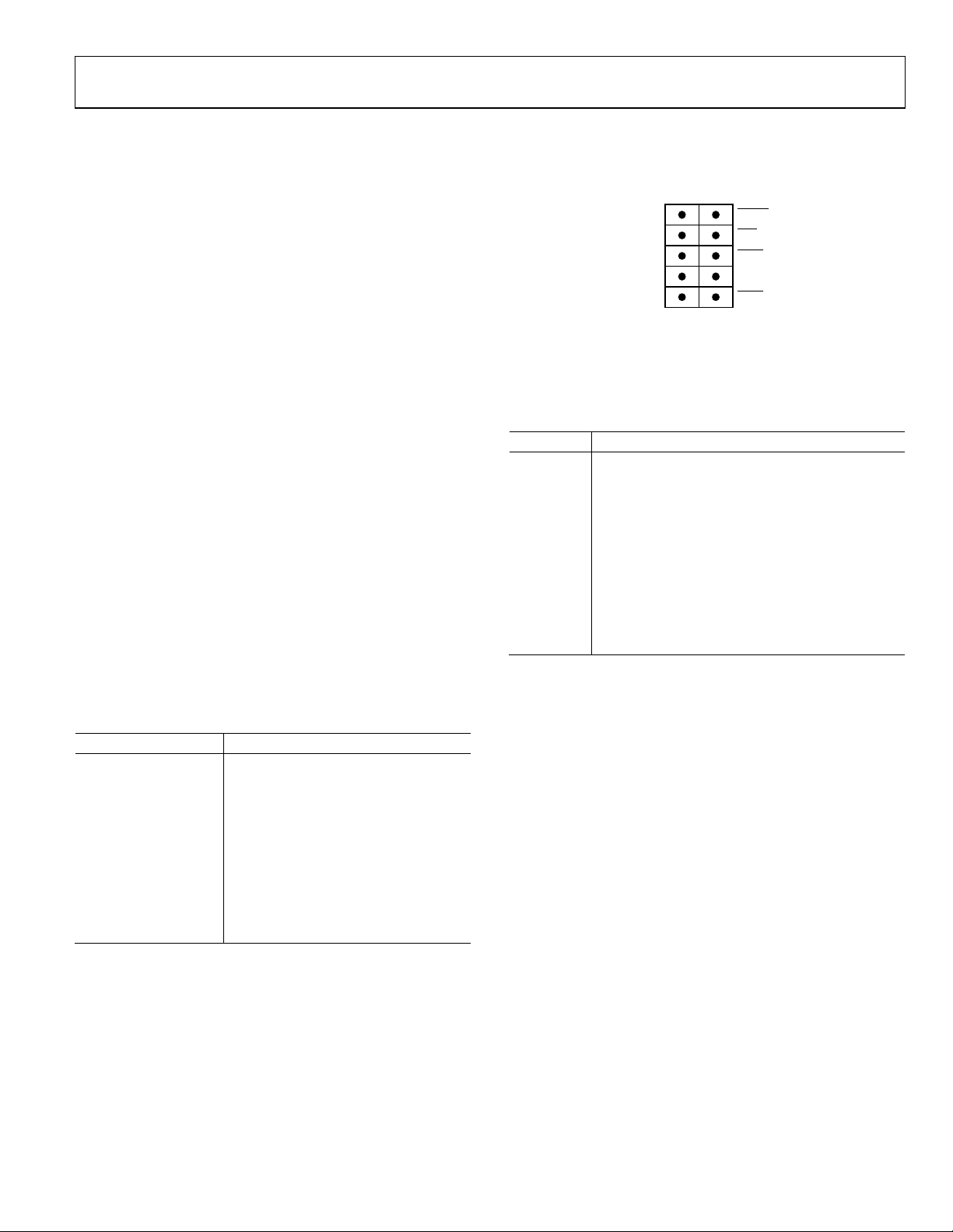
FUNCTIONAL BLOCK DIAGRAM
Figure 1.
Rev. 0 | Page 1 of 16

UG-342 Evaluation Board User Guide
TABLE OF CONTENTS
Features .............................................................................................. 1
Evaluation Board Description......................................................... 1
Device Description ........................................................................... 1
Functional Block Diagram .............................................................. 1
Revision History ............................................................................... 2
Evaluation Board Hardware ............................................................ 3
Power Supplies .............................................................................. 3
Link Options ................................................................................. 3
REVISION HISTORY
11/11—Revision 0: Initial Version
On-Board Connectors ..................................................................3
Evaluation Board Software ...............................................................5
Software Installation .....................................................................5
Software Operation .......................................................................5
Main Window ................................................................................6
Evaluation Board Schematics and Artwork ...................................8
Ordering Information .................................................................... 14
Bill of Materials ........................................................................... 14
Rev. 0 | Page 2 of 16
Evaluation Board User Guide UG-342
LK6
Removed
LK7
Removed
SDO RESET
1
2
DGND CLR
3
4
DGND LDAC
5
6
SDIN DGND
7
8
SCLK SYNC
9
10
10344-015
Connector
Function
J2
Analog power supply connector
EVALUATION BOARD HARDWARE
POWER SUPPLIES
The following external supplies must be provided:
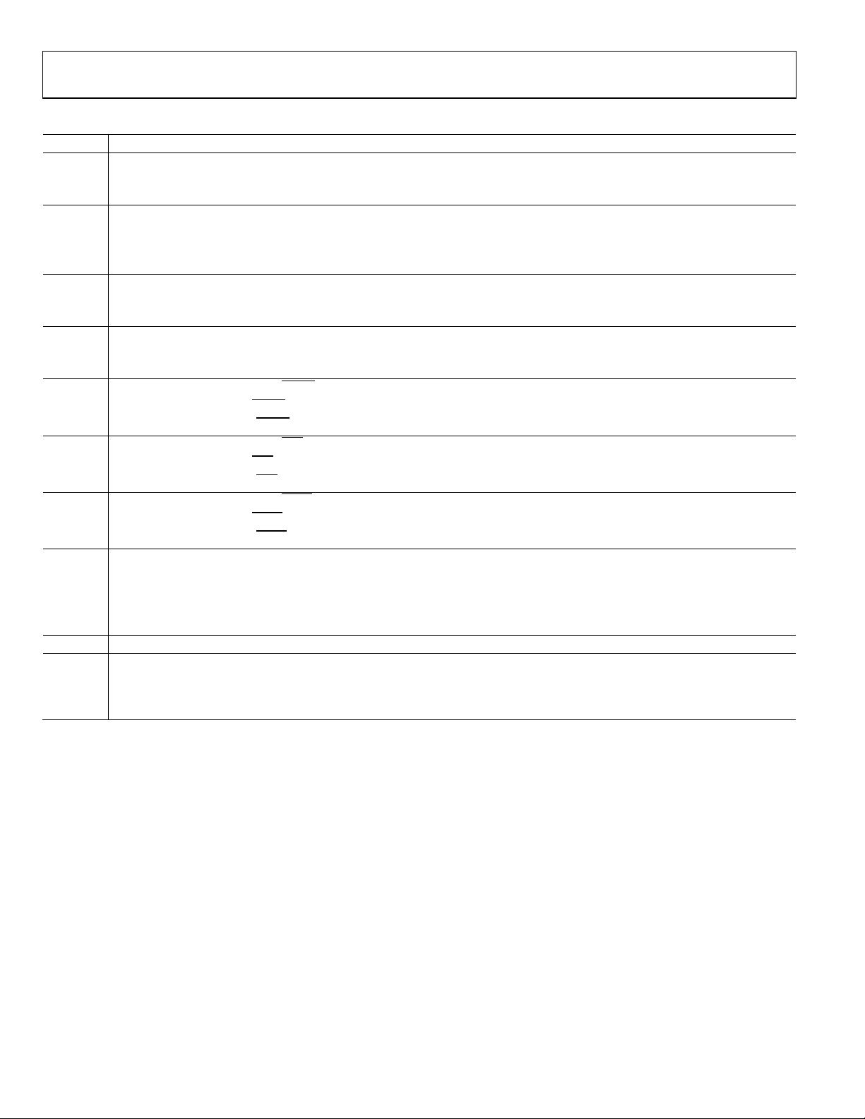
Connector J3 Pin Configuration
Figure 2 shows the pin configuration of Connector J3.
• 5 V between the V
and DGND inputs for the digital
CC
supply of the AD5790. Alternatively, place Link 1 in
Position A to power the digital circuitry from the USB
port via the SDP board (default).
• 7.5 V to 16.5 V between the V
and AGND inputs for
DD
the positive analog supply of the AD5790.
• −2.5 V to −16.5 V between the V
and AGND inputs for
SS
the negative analog supply of the AD5790.
The analog and digital planes are connected at one location,
close to the AD5790. To avoid ground loop problems, it is
recommended not to connect AGND and DGND elsewhere in
the system.
Each supply is decoupled to the relevant ground plane with
10 µF and 0.1 µF capacitors. Each device supply pin is again
decoupled with a 10 µF and 0.1 µF capacitor pair to the relevant
ground plane.
LINK OPTIONS
The link options on the evaluation board should be set for the
required operating setup before using the board. The functions
of the link options are described in Tabl e 3.
Default Link Option Setup
The default link options are listed in Table 1. By default, the
board is configured with V
a ±10 V output range.
= +10 V and V
REFP
= −10 V for
REFN
Figure 2. Connector J3 Pin Configuration
ON-BOARD CONNECTORS
There are nine connectors on the AD5790 evaluation board
PCB as outlined in Table 2.
Table 2. On-Board Connectors
J1 Digital power supply connector
J3 Digital interface pin header connector
J4 SDP board connector
VOUT DAC output connector
VOUT_BUF Buffered DAC output connector
VREF 5 V external reference voltage input connector
(+10 V, +5 V, −10 V, and −5 V reference voltages are
generated from this 5 V input or on-board ADR445)
VREFN DAC negative reference input connector
VREFP DAC positive reference input connector
Table 1. Default Link Options
Link No. Option
LK1 A
LK2 B
LK3 A
LK4 Removed
LK5 Removed
LK8 C
LK9 Inserted
LK11 Inserted
Rev. 0 | Page 3 of 16
UG-342 Evaluation Board User Guide
Position A configures the amplifier in unity gain. LK4 should be removed.1
When this link is inserted,
is at logic low.
Position A selects an on-board generated −5 V.
Table 3. Link Options
Link No. Description
LK1 This link selects the source of the digital power supply.
Position A selects the source from the SDP board.
Position B selects the source from Connector J1.
LK2 This link selects the positive reference voltage source.
Position A selects an on-board generated 5 V.
Position B selects an on-board generated 10 V.
Position C selects an external voltage applied at Connector VREFP.
LK3 This link is used in conjunction with LK4 to configure the mode of operation of the output amplifier.
Position B configures the amplifier for a gain of 2. Lk4 should be inserted.2
LK4 This link is used in conjunction with LK3 to configure the mode of operation of the output amplifier.
When this link is inserted, LK3 should be in Position B to configure the amplifier for a gain of 2.2
When this link is removed, LK3 should be in Position A to configure the amplifier for unity gain.1
LK5 This link selects the state of the
When this link is inserted,
When this link is removed,
RESET
RESET
LK6 This link selects the state of the
When this link is inserted,
When this link is removed,
is at logic low.
CLR
CLR
LK7 This link selects the state of the
LDAC
When this link is removed,
LDAC
LK8 This link selects the negative reference voltage source.
pin.
RESET
is at logic low.
is at logic high.
pin.
CLR
is at logic high.
pin.
LDAC
is at logic high.
Position B selects AGND.
Position C selects an on-board generated −10 V.
Position D selects an external voltage applied at Connec tor VREFN.
LK9 This link connects the output of Voltage Reference U5 to the reference scaling circuitry.
LK11 This link connects the DAC output to the noninverting input of the output buffer amplifier.
When this link is inserted, the DAC output is connected to the noninverting input of the output amplifier.
When this link is removed, the DAC output is disconnected from the noninverting input of the output buffer amplifier and the
DAC output voltage is accessible at the VOUT connector.
1
The RBUF bit of the control register must be set to high to enable the unity-gain mode of operation.
2
The RBUF bit of the control register must be cleared to low to enable the gain of 2 mode of operation.
Rev. 0 | Page 4 of 16

Evaluation Board User Guide UG-342
10344-002
10344-003
EVALUATION BOARD SOFTWARE
SOFTWARE INSTALLATION
The AD5790 evaluation kit includes self-installing software on
a CD. The software is compatible with Windows XP (SP2) and
Vista (32-bit or 64-bit). If the setup file does not run automatically, you can run the setup.exe file from the CD.
Install the evaluation software before connecting the evaluation
board and SDP board to the USB port of the PC to ensure that
the evaluation system is correctly recognized when connected
to the PC.
1. After installation from the CD is complete, power up the
AD5790 evaluation board as described in the Power Supplies
section. Connect the SDP board (via either Connector A or
Connector B) to the AD5790 evaluation board and then
to the USB port of your PC using the supplied cable.
2. When the evaluation system is detected, proceed through any
dialog boxes that appear. This completes the installation.
SOFTWARE OPERATION
To launch the software, complete the following steps:
1. From the Start menu, select Analog Devices, AD5790,
then AD5790 Evaluation Software. The main window of
the software then opens (see Figure 4).
2. If the evaluation system is not connected to the USB port
when the software is launched, a connectivity error displays
(see Figure 3). Connect the evaluation board to the USB
port of the PC, wait a few seconds, click Rescan, and follow
the instructions.
Figure 3. Connectivity Error Alert
Figure 4. Main Window
Rev. 0 | Page 5 of 16
 Loading...