

Page 1
t e m p e r a t u r e
Specification Sheet
SS-CP-2284-US
Model ATC-140/250
Advanced Temperature
Calibrator
Wide temperature range
ATC-140 -20 to 140°C (-4 to 284°F)
ATC-250 28 to 250°C (82 to 482°F)
Liquid bath or dry-block
Use ATC-140 and ATC-250 as liquid bath
or large diameter dry-block calibrator
Improved temperature homogeneity
Unique dual-zone block ensures good
temperature homogeneity in the critical
calibration zone
High accuracy
Using the internal reference or the external reference probe. 4-wire True-OhmMeasurement technology is used
Enhanced stability
MVI circuitry ensures temperature stability
despite mains supply variations
Cost effective calibration system
Stand-alone operation eliminates the
need for secondary equipment and PC.
Universal inputs handle multiple type temperature sensors
Timesaving features
Up- and download complete calibration
tasks. Auto-stepping, switch testing and
many more features make the daily use
smooth and fast
Documentation made easy
RS232 communication and JOFRACAL
calibration software are included in the
standard delivery
Complete marine program
Part of a complete program of marine
approved temperature, pressure and signal
calibrators; including temperature sensors
PRODUCT DESCRIPTION
The JOFRA ATC series
(Advanced Temperature
Calibrators) combines the
accuracy of laboratory
temperature sources with
the speed and portability
of field dry-block calibrators.
With the JOFRA ATC-140
and ATC-250 (Advanced
Temperature Calibrators)
it is possible to calibrate
even more sensors at the same time and to calibrate large and odd
size sensors in either a large diameter dry-block or in a liquid bath.
Features
JOFRA ATC-140 and ATC-250 both features the unique dual-zone heating block - designed for optimum performance and superior temperature
homogeneity throughout the block. This new design has a performance
equivalent to a liquid temperature bath.
Each ATC dry-block calibrator may be used to perform fully automatic
calibration routines without using an external computer. Use the computer for full upload and download capabilities. Units may also be supplied
with inputs for external reference sensors and for sensors-under-test. All
ATC calibrators feature RS232 serial communication and standard delivery also includes the JOFRACAL calibration PC software.
The ATC-140 and ATC-250 calibrators are part of a serie of calibrators, that also includes the ATC-156, ATC-157, ATC-320 and ATC-650
dry-block calibarators covering temperature ranges between -45°C and
650°C.
See more about the ATC-156, ATC-157, ATC-320 and ATC-650 calibrators at page 5 or in specification sheet SS-CP-2285 at www.jofra.com
ISO 9001 Manufacturer
Page 2
Model ATC-140/250
Advanced Temperature Calibrator
Specification Sheet
SS-CP-2284-US
Unique temperature performance
The ATC series of calibrators provide precision temperature calibration of sensors; whatever the type or format.
This is accomplished through an innovative dual-zone
heating technology.
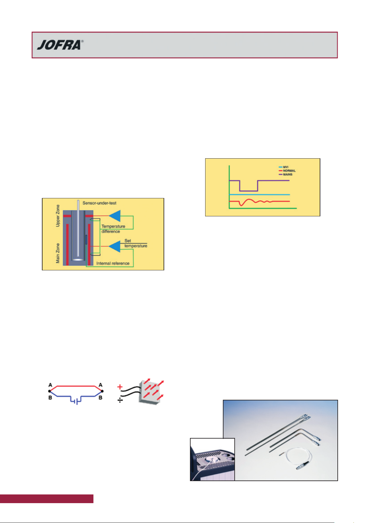
Both the ATC-140 and ATC-250 feature a dual-zone heating technology. Each heating zone is independently controlled for precision temperature calibration. The homogeneity in the lower part is close to that of a laboratory liquid
bath. The lower zone ensures optimum heat dissipation
throughout the entire calibration zone. The upper zone
compensates for heat loss from the sensor-under-test
and from the open top. This design also eliminates the
need for insulation of the sensors-under-test and makes
it possible to calibrate liquid-filled and other mechanical
sensors.
MVI - Improved temperature stability
MVI stands for ’’Mains power Variance Immunity’’.
Unstable mains power supplies are a major contributor to
on-site calibration inaccuracies. Traditional temperature
calibrators often become unstable in production environments where large electrical motors, heating elements,
and other devices are periodically cycled on or off. The
cycling of supply power can cause the temperature regulator to perform inconsistently leading to both inaccurate
readings and unstable temperatures.
The JOFRA ATC-250 calibrator employ the MVI, thus
avoiding such stability problems. The MVI circuitry continuously monitors the supply voltage and ensures a constant energy flow to the heating elements.
The ATC-140 models run on stabilized DC voltage and
thus do not need the MVI circuitry.
ATC heating and cooling models
The ATC-140 model with both heating and cooling capabilities
feature the Peltier element multi-stage-technology. This
both improves efficiency and extends the life of the »electronic heat pump«.
Peltier effect (ATC-140)
In 1834, Jean Peltier, a French physicist found that an
’’opposite thermocouple effect’’ could be observed when
an electric current was connected to a thermocouple. Heat
would be absorbed at one of the junctions and discharged
at the other junction. This effect is called the ’’PELTIER
EFFECT’’.
The practical Peltier element (electronic heating pump)
consists of many elements of semiconductor material connected electrically in series and thermally in parallel. These
thermoelectric elements and their electrical interconnections are mounted between two ceramic plates. The plates
serve to mechanically hold the overall structure together
and to electrically insulate the individual elements from
one another.
Highest accuracy (model B only)
ATC series calibrators may be supplied with a built-in reference thermometer for use with an external probe. This
feature allows one instrument to provide the freedom and
flexibility to perform calibrations at the process site while
maintaining a high accuracy.
A special 90° angled external reference sensor has been
designed to accommodate sensors with a transmitter
head, top connector or similar arrangement.
The user can decide whether to read the built-in reference sensor or the more accurate angled reference sensor
from the calibrator’s large, easy-to-read LCD display. The
external sensor and the internal sensor are independent of
one another. Downloading of reference sensor linearization
is done via a personal computer.
Please find more information about JOFRA STS reference
sensors in specification sheet: SS-CP-2290 at www.jofra.
com.
2 www.jofra.com
Page 3
Model ATC-140/250
Advanced Temperature Calibrator
Specification Sheet
SS-CP-2284-US
SET-Follows-TRUE (model B only)
Available on B models only, the “SET-Follows TRUE”
makes the instrument tune in until the temperature of
the external reference “TRUE” meets the desired “SET”
temperature. This is used when it is critical that the temperature of the calibration zone matches the desired temperature when measured with accurate external reference
sensors.
This feature is ideal when calibrating gas correctors or
other custody transfer applications. It is also extremely
useful to calculation procedures.
Reading of sensor-under-test (model B only)
The ATC series model B is equipped with built-in converters (inputs) that enables measurement of virtually any type
of temperature sensor including:
thermostats
•
resistance thermometers (RTD)
•
thermocouples (TC)
•
transmitters
•
milliamps (mA)
•
voltage (V)
•
The ATC calibrators can be user-programmed for completely automated temperature calibrations. Once the unit
is programmed, the instrument operates itself by performing the configured calibration routine. All calibration data
is stored and available for uploading and generating exact
calibration certificates or reports.
Switch test (model B only)
Users may perform a thermoswitch test and find “Open”,
“Closed” and the hysteresis (deadband) automatically. The
instrument retains the last five tests.
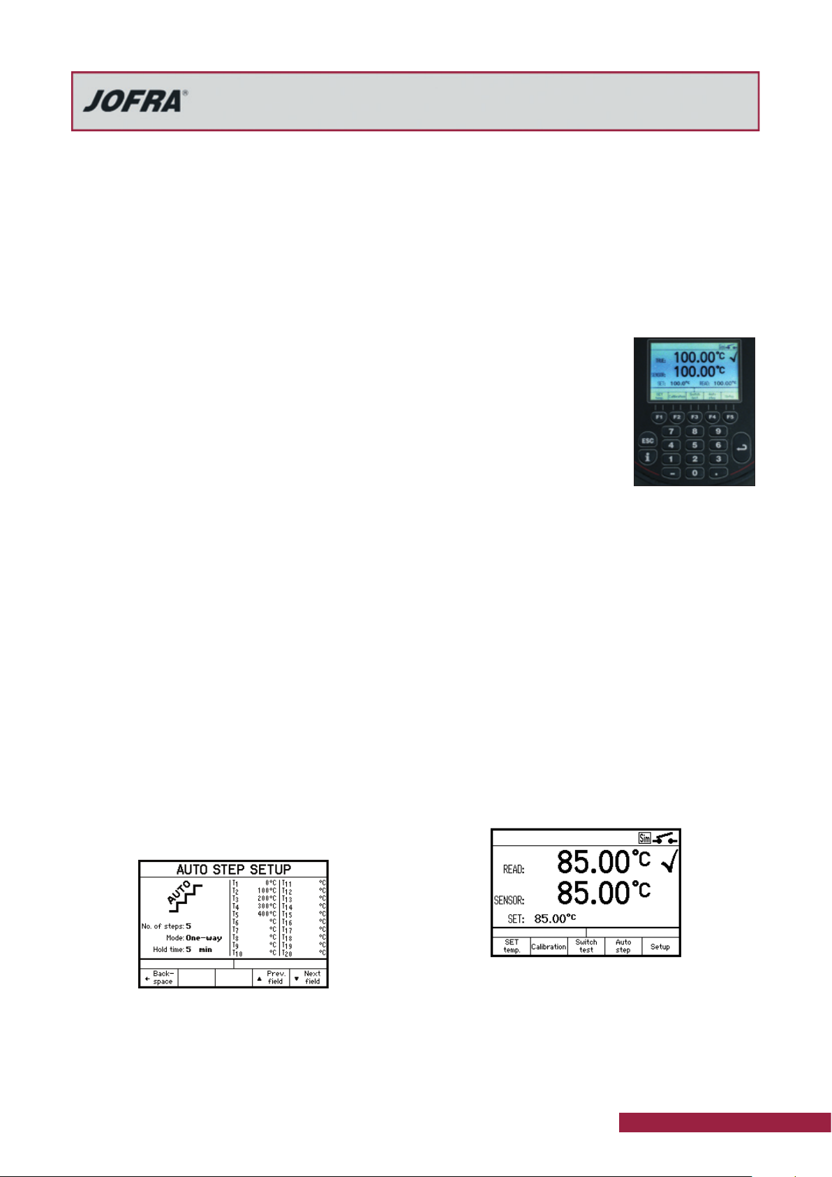
Auto-stepping
Up to 20 different temperature steps may be programmed
including the hold time for each step. Upon completion of
an auto step routine, the user can easily read the results
for the sensor-under-test. Up to five (5) auto step results
are stored.
Easy-to-use, intuitive operation
All instrument settings can be performed from the front
panel. The heat source is positioned away from the panel
which helps protect the operator.
The ATC keyboard is equipped with five, positive feedback
function keys. They correspond to the text in the display
and change functionality based on instrument operations.
There are also dedicated function keys with permanent
functions.
The easy-to-read, backlit display
is large with a high contrast that
is readible even in high ambient
light conditions. The display is
easily read from all angles and
from a distance without parallax
problems. The display also features icons which help identifying
instrument conditions and operational steps, making it more intuitive to work with.
Set temperature
The “Set temperature” feature allows the user to set the
exact desired temperature with a resolution of 0.01°.
Enhanced stability
A stability indicator shows when the ATC calibrator has
reached the desired temperature and is stable. The user
may change the stability criteria, external reference and
the sensor-under-test quickly and simply. The stability
criteria is the user’s security for a correct calibration. A
count-down timer is displayed next to the temperature
read-out.
Instrument setups
The ATC series allows the user to store up to nine (9)
complete instrument setups. You may store all sorts of
information including temperature units, stability criteria,
use of external reference sensor, resolution, sensor-undertest (SUT), conversion to temperature, display contrast,
etc. The setup may be recalled at any time.
Maximum temperature
From the setup menu, the user can select the maximum
temperature limit for the calibrator. This function prevents
damage to the sensor-under-test caused by the application of excessive temperatures. The feature also aids in reducing drift resulting from extended periods of exposures
to high temperatures. This feature can be locked with an
access code.
www.jofra.com 3
Page 4
Model ATC-140/250
Advanced Temperature Calibrator
Specification Sheet
SS-CP-2284-US
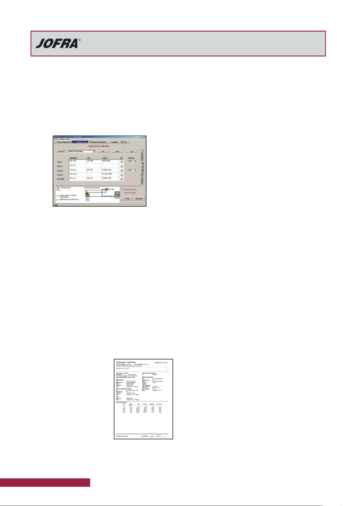
JOFRACAL CALIBRATION SOFTWARE
JOFRACAL calibration software ensures easy calibration
of RTD´s, thermocouples, transmitters, thermoswithes,
pressure gauges and pressure switches. JOFRACAL can
be used with JOFRA DPC-500, APC, CPC and IPI pressure calibrators, all JOFRA temperature calibrators, as well
as JOFRA AMC900, ASC300 multi signal calibrator and
ASM-800 signal multi scanner.
JOFRACAL calibration software may also be used for
manual calibrations, as it can be set up to accept manual
entry of calibration data together with other liquid baths,
ice points or dry-block heat sources.
The calibration data collected may be stored on a PC for
later recall or analysis. The ATC calibrator stores the calibration procedure and may be taken out to the process
site without using a personal computer.
This allows the ATC calibrator to:
•
Operate as a stand-alone instrument, using advanced
calibration routines without the assistance of a
personal computer on site;
•
Prevent unauthorized changes to a calibration routine.
Personnel who are not authorized to alter a calibration
routine cannot do so.
As found/as left (model B only)
The JOFRA ATC series calibrator automatically handles
“As Found/As Left” calibrations. The calibrator stores both
results. The first performed calibration is “As found” and
the last performed calibration is the “As left”, regardless
of the number of calibrations/adjustments that may have
been made in between.
SYNC output
An output is located directly on the front of the ATC calibrator. This output signals when the instrument is stable
and may be used with ancillary devices such as video
recorders, digital cameras or as an input to a data logging
device. The SYNC output may be useful for automating
and documenting your calibrations when calibrating external reading devices.
Calibration (model B only)
Users may perform or read the results of the calibration
tasks directly on the instrument. When calibrating an indicating device, users may key in the results during or after the
test. Using the “Calibration info” function, the user may view
the complete calibration task, including the “Scenario” before the calibration takes place.
Calibration of up to 24 sensors with JOFRA ASM
Using the JOFRA ATC series together with the ASM
Advanced Signal Multi-scanner offers a great time-saving
automatic solution to calibrate multiple temperature sensors at the same time. The ASM series is an eight channel
scanner controlled by the JOFRACAL software on a PC.
Up to 3 ASM units can be stacked to calibrate up to 24
sensors at the same time. It can handle signals from 2-,
3- and 4 wire RTD’s, TC’s, transmitters, thermisters, temperature switches and voltage.
Please also see more in specification sheet SS-CP-2360,
which can be found at www.jofra.com
Once all calibrations are completed, the data may be
uploaded to the JOFRACAL calibration software for postprocessing and printing of certificates. The calibration data
collected may be stored on the personal computer for
later recall or analysis.
The JOFRACAL temperature
calibration software may be
donwloaded free of charge from
our web-page www.jofra.com.
Please also see more about
JOFRACAL calibration software
in specification sheet SS-CP2510, which can be found at
www.jofra.com
4 www.jofra.com
JOFRACAL software
Minimum hardware requirements for JOFRACAL calibration software.
INTELTM 486 processor
•
(PENTIUMTM 800 MHz recommended)
•
32 MB RAM (64 MB recommended)
•
80 MB free disk space on hard disk prior to installation
•
Standard VGA (800 x 600, 16 colors) compatible screen
•
(1024 x 786, 256 colors recommended)
•
CD-ROM drive for installation of the program
•
1 free RS232 serial port
•
Page 5

Model ATC-140/250
Advanced Temperature Calibrator
Specification Sheet
SS-CP-2284-US
FUNCTIONAL COMPARISON
ATC series
ATC-125 A
Temperature range @ ambient 23°C / 73°F
-90 to 125°C -130 to 257°F X X
-20 to 140°C -4 to 284°F X X
-24 to 155°C -11 to 311°F X X
-45 to 155°C -49 to 311°F X X
28 to 250°C 82 to 482°F X X
33 to 320°C 91 to 608°F X X
33 to 650°C 91 to 1202°F X X
Temperature stability
±0.01°C ±0.018°F S S S S S S
±0.02°C ±0.036°F X X X X S S
±0.03°C ±0.054°F X X
Accuracy incl. external STS reference sensor
±0.04°C ±0.07°F X
±0.06°C ±0.11°F X X
±0.07°C ±0.13°F X 1X
±0.11°C ±0.2°F X
Accuracy with internal reference sensor
±0.10°C ±0.18°F S S
±0.13°C ±0.23°F S S
±0.18°C ±0.32°F S S
±0.20°C ±0.36°F S S
±0.28°C ±0.50°F S S
±0.30°C ±0.54°F X X
±0.35°C ±0.63°F S S
Immersion depth
185 mm 7.3 in X X
180 mm 7.1 in X 2X
160 mm 6.3 in X X X X
150 mm 5.9 in X 3X
Insertion tube diameter
63.5 mm 2.5 in X X X X
30 mm 1.2 in X X X X X X X X
20 mm 0.8 in X X
Dual-zone heating/cooling block • •
MVI - Mains Variance Immunity (or similar) • •
Stability indicator • •
Automatic step function • •
JOFRACAL Calibration software included as standard • •
SYNC output (for external recording device) • •
Display resolution 0.01° • •
Programmable max. temperature • •
Input for RTD, TC, V, mA •
4-20 mA transmitter input incl. 24 VDC supply •
All inputs scalable to temperature •
Automatic switch test (open, close and hysteresis) •
External precision reference probe input •
Download of calibration work orders from PC •
Upload of calibration results (as found & as left) •
“SET” follows “TRUE” •
ATC-140 A
ATC-125 B
ATC-156 A
ATC-140 B
1
X
2
3
ATC-157 A
ATC-156 B
1
ATC-250 A
ATC-157 B
1
X
Model A Model B
ATC-250 B
X 4X X X X X
ATC-320 A
ATC-320 B
1
ATC-650 A
ATC-650 B
1
JOFRA ATC-156/157/320/650
For a wider product description of
the ATC-156/157/320/650 please
see spec. sheet SS-CP-2285, at
www.jofra.com
JOFRA ATC-125
For a wider product description
of the ATC-125 please see spec.
sheet SS-CP-2282, at www.jofra.
com
X = Delivered as standard
S = Improved specifications
(from October 01, 2006)
1
Using an external STS reference sensor
connected to the reference probe input
2
Immersion depth for ATC-140 as dry-block
3
Immersion depth for ATC-140 as liquid bath
4
Immersion depth for ATC-250 as dry-block and
as liquid bath
www.jofra.com 5
Page 6

Model ATC-140/250
Advanced Temperature Calibrator
Specification Sheet
SS-CP-2284-US
Liquid bath / large diameter insert
The ATC-140 and ATC-250 are fitted with a 150 mm (5.9
in) deep well with a diameter of 63.5 mm (2.5 in) can be
used both as dry-block calibrators and as liquid calibration
baths with a magnetic stirrer.
A liquid bath and a dry-block diameter of 63.5 mm (2.5 in),
which is twice the size of any other JOFRA dry-block, are
both new in the JOFRA product range. With these options
it is now possible to calibrate even more temperature sensors at the same time and to calibrate large as well as odd
sizes and shapes of sensors, which is not possible to calibrate in the remaining product range.
ATC-140 & ATC-250 can be used without an external
reference sensor, but if a STS-100 reference sensor is
connected directly to a B version or the JOFRA reference
thermometer DTI-1000, you obtain better accuracies and
thereby use the full potential of the calibrators.
Liquid bath versus dry-block kit
The basic advantages of the liquid bath configuration versus the dry-block configuration are as follows:
You do not need insertion tubes for all your different
•
types of sensors
You can calibrate sensors, which do not fit into
•
insertion tubes
You can calibrate glass thermometers and gas or liquid
•
filled sensors
The basic advantages of the dry-block configuration
•
versus the liquid bath configuration are the following:
No hazardous hot liquids
•
Easier to handle insertion tubes than liquids
•
More convenient to carry than when filled with liquid
•
No need for external exhaustion
•
All specifications given in the liquid bath configuration are
based on the silicone oil supplied and recommended by
JOFRA.
Why ATC-140 and ATC-250?
Calibration of many sensors at the same time due to more space for
example in connection with validation of many thermocouples, which
saves time
Calibration of as many as 24 sensors at the same time by using 3
•
JOFRA ASM Signal Multi-Scanners
For customers, who only want to use liquid baths
•
For calibration of odd sizes and shapes of sensors
•
WET = no need for inserts, which fit the sensors
DRY = more space for calibration of special sensors
The Pharmaceutical industry often wants to calibrate more sensors
•
at the same time and often has many short sensors
The Food industry often has odd sizes and shapes of sensors
•
including sanitary ones
The JOFRACAL software and the ATC B-models on-line can handle
•
the calibration and documentation of multiple sensors calibrated at
the same time. However, you need to change the input connection
manually one-by-one
6 www.jofra.com
Page 7

Model ATC-140/250
Advanced Temperature Calibrator
Specification Sheet
SS-CP-2284-US
CONFIGURATIONS
Liquid bath kit for ATC-140 A/B and ATC-250 A/B
1 x Sensor basket
2 x Covering lids
1 x Magnet – for the
magnetic stirrer
1 x Magnet remover
1 x Liquid drainage tube
1 x Silicone oil 0,75 l
(25.4 oz)
It is also possible to order
extra silicone oil and a
support rod for sensors,
which can be mounted on
the side of all JOFRA dryblock calibrators and hold
the sensors under test in
the correct position during calibraton.
The support rod is especially important, when
working with liquid baths
and do not have the
inserts to hold the sensors under test.
Dry-block kit for the ATC-140 A/B and ATC-250
A/B
1 x Multi-hole insert - it is possible to choose between a
metric and an imperial version:
The metric version has holes for the following sizes of sensors: 1 x 12, 1 x 11, 1 x 9, 1 x 8, 2 x 6, 1 x 5, 2 x 4, 1 x 3
mm and
1 x 1/4 in.
The imperial version has holes for the following sizes of
sensors: 1 x 1/8 in, 1 x
3/16 in, 1 x 1/4 in, 1 x
5/16 in, 1 x 3/8 in, 1 x
7/16 in, 1 x 1/2 in, 1 x
9/16 in, 1 x 5/8 in and 1
x 4 mm.
1 x Insulation plug for
the ATC-140.
It is also possible to
order undrilled and special drilled inserts.
PHYSICAL SPECIFICATIONS
Instrument dimensions (L x W x H)
All models ........ 352 x 156 x 360 mm / 13.9 x 6.1 x 14.2 in
Instrument weight
ATC-140 ..................................................... 12.8 kg / 28.2 lb
ATC-250 ..................................................... 10.8 kg / 23.8 lb
Insert dimensions
ATC-140/250 outer diameter ............................63.5 / 2.5 in
ATC-140/250 inner diameter ....................57,5 mm / 2.26 in
ATC-140/250 length ..................................160 mm / 6.30 in
Weight of non-drilled insert (approximate)
ATC-140 ..................................................... 1200 g / 42.3 oz
ATC-250 ..................................................... 1200 g / 42.3 oz
Shipping (including optional carrying case)
ATC-140 * ...................................................23.4 kg / 51.6 lb
ATC-250 * ...................................................21.3 kg / 47.0 lb
Size: L x W x H .. 670 x 309 x 514 mm / 26 x 12.2 x 20.2 in
Shipping (without carrying case)
ATC-140 * ...................................................16.7 kg / 36.8 lb
ATC-250 * ...................................................14.6 kg / 32.2 lb
Size: L x W x H . 570 x 235 x 440 mm / 22.4 x 9.3 x 17.3 in
Shipping (carrying case only)
Weight: ........................................................6.0 kg / 13.2 lb
Size: L x W x H .. 670 x 309 x 514 mm / 26 x 12.2 x 20.2 in
Miscellaneous
Serial data interface ............................. RS232 (9-pin male)
Operating temperature ....................0 to 40°C / 32 to 104°F
Storage temperature .................. -20 to 50oC / -4 to 122oF
Humidity ......................................................... 0 to 90% RH
Protection class ..........................................................IP-10
DNV Marine Approval, Certificate no ......................A-10384
*If a dry-block or liquid bath kit is ordered, there will be an extra
collie of approximately 2 kg (4.4 lb).
www.jofra.com 7
Page 8

Model ATC-140/250
Advanced Temperature Calibrator
Specification Sheet
SS-CP-2284-US
FUNCTIONAL SPECIFICATIONS
Mains specifications
ATC-140/250 ........................ 115V(90-127) / 230V(180-254)
Frequency, non US deliveries ............... 50 Hz ±5, 60 Hz ±5
Frequency, US deliveries .......................................60 Hz ±5
Power consumption (max.) ATC-140 ........................300 VA
Power consumption (max.) ATC-250 ......................1150 VA
Temperature range
ATC-140 Maximum (Dry block) ..................... 140°C / 284°F
Minimum @ ambient temp. 0°C / 32°F .........-35°C / -31°F
Minimum @ ambient temp. 23°C / 73°F ...........-20°C / -4°F
Minimum @ ambient temp. 40°C / 104°F .......... -5°C / 23°F
ATC-140 Maximum (Liquid bath) .................. 140°C / 284°F
Minimum @ ambient temp. 0°C / 32°F .........-33°C / -27°F
Minimum @ ambient temp. 23°C / 73°F ............ -18°C / 0°F
Minimum @ ambient temp. 40°C / 104°F .......... -3°C / 27°F
ATC-250 (Dry block) ....................28 to 250°C / 82 to 482°F
ATC-250 (Liquid bath) .................28 to 250°C / 82 to 482°F
Stability
ATC-140/250 ........................................... +0.02°C / +0.04°F
Measured after the stability indicator has been on for 15 minutes.
Measuring time is 30 minutes.
Time to stability (approximate)
ATC-140/250 ...................................................... 15 minutes
Accuracy (model B) with external STS reference sensor
ATC-140 .................................................. +0.04°C / +0.07°F
ATC-250 .................................................. +0.07°C / +0.13°F
12 month period. Relative to reference standard. Specifications
by use of the external JOFRA STS-100 reference sensor (see
specification sheet SS-CP-2290, which can be found at www.
jofra.com)
Accuracy (model A+B) with internal reference sensor
ATC-140 A+B .................................. +0.18°C / +0.32°F 1) 2)
ATC-250 A+B .................................. +0.28°C / +0.50°F 1) 3)
12 month period. Specifications by use of the internal reference sensor.
1) Improved specifications (from October 1, 2006)
2) When used with the dry-block kit. When used with the liquid
bath kit the standard accuracy is ±0.30°C (0.54°F).
3) When used with the dry-block kit. When used with the liquid
bath kit the standard accuracy is ±0.50°C (0.90°F).
Better accuracy with the liquid kits is obtainable, if a special calibration and adjustment are done with liquid.
Resolution (user-selectable)
All temperatures ..................................... 1° or 0.1° or 0.01°
Radial homogeneity (difference between holes)
ATC-140/250 (dry-block) .............................. 0.05°C /0.09°F
ATC-140/250 (liquid bath) ....................... 0.025°C / 0.045°F
Immersion depth
ATC-140 (dry-block) ....................................180 mm / 7.1 in
ATC-140/250 (liquid bath) ........................... 150 mm / 5.9 in
ATC-250 (dry-block) ....................................150 mm / 5.9 in
Well diameter
ATC-140 .......................................................... 63.8 / 2.51 in
ATC-250 .......................................................... 63.8 / 2.51 in
Heating time
ATC-140 -20 to 23°C / -4 to 73°F ............... 10 minutes
23 to 100°C / 73 to 212°F ...........
100 to 140°C / 212 to 284°F .......
ATC-250 50 to 250°C / 122 to 482°F .........
31 minutes
23 minutes
11 minutes
Cooling time
ATC-140 140 to 100°C / 284 to 212°F ......... 7 minutes
100 to 23°C / 212 to 73°F ...........
23 to 0°C / 73 to 32°F .................
0 to -15°C / 32 to 5°F ..................
ATC-250 250 to 100°C / 482 to 212°F .......
100 to 50°C / 212 to 122°F .........
27 minutes
17 minutes
35 minutes
27 minutes
27 minutes
SYNC output (dry contact)
Switching voltage ................................... Maximum 30 VDC
Switching current ...................................Maximum 100 mA
INPUT SPEC’S (B MODELS ONLY)
All input specifications apply to the calibrator’s dry-block running at the respective temperature (stable plus an additional 20
minutes period). Where the input measuring range is out of the
calibrator’s range, the SET temperature is either MIN. or MAX.
Transmitter supply
Output voltage ................................................ 24VDC +10%
Output current .......................................... Maximum 25 mA
Transmitter input mA
Range ................................................................. 0 to 24 mA
Accuracy (12 months) ............. +0.01% Rdg. +0.015% F.S.
Voltage input VDC
Range: .............................................................. 0 to 12 VDC
Accuracy (12 months) ........... +0.005% Rdg. +0.015% F.S.
Switch input
Switch dry contacts
Test voltage ............................................... Maximum 5 VDC
Test current .............................................. Maximum 2.5 mA
RTD reference input (B models only)
Type .................4-wire RTD with true ohm measurements1)
F.S. (Full Scale) ...................................................... 350 ohm
Accuracy (12 months) ............±0.001% rdg. + 0.002% F.S.
RTD Type Temperature 12 months
°C °F °C °F
Pt100
reference
Note 1: True ohm measurements are an effective method to eliminate errors from induced thermoelectrical voltages
-50 -58 ±0.020 ±0.036
0 32 ±0.021 ±0.038
155 311 ±0.023 ±0.041
320 608 ±0.026 ±0.047
650 1202 ±0.032 ±0.058
700 1292 ±0.034 ±0.061
8 www.jofra.com
Page 9

Model ATC-140/250
Advanced Temperature Calibrator
Specification Sheet
SS-CP-2284-US
RTD input
Type of RTD ............................................................... 2-wire
F.S. (range) ....................................... 350 ohm or 2900 ohm
Accuracy (12 months) ..........................................................
.............................. ±(0.005% rdg. + 0.005% F.S. + 50 mΩ)
Type of RTD ...................................................... 3- or 4-wire
F.S. (range) ....................................... 350 ohm or 2900 ohm
Accuracy (12 months) ..........±(0.005% rdg. + 0.005% F.S.)
RTD Type Temperature 12 months
°C °F °C °F
Pt1000
Pt500
Pt100
Pt50
(only in
Russian
versions)
Pt10
Cu100
Cu50
-50 -58 ±0.046 ±0.083
0 32 ±0.050 ±0.090
155 311 ±0.061 ±0.110
320 608 ±0.071 ±0.127
500 932 ±0.087 ±0.156
-50 -58 ±0.083 ±0.149
0 32 ±0.087 ±0.157
155 311 ±0.100 ±0.180
320 608 ±0.111 ±0.200
500
-50 -58 ±0.054 ±0.097
0 32 ±0.058 ±0.104
155 311 ±0.069 ±0.124
320 608 ±0.079 ±0.142
650 1202 ±0.106 ±0.191
700 1292 ±0.112 ±0.202
-50 -58 ±0.098 ±0.176
0 32 ±0.103 ±0.185
155 311 ±0.116 ±0.209
320 608 ±0.128 ±0.230
650 1202 ±0.161 ±0.290
700 1292 ±0.169 ±0.303
-50 -58 ±0.453 ±0.815
0 32 ±0.462 ±0.831
155 311 ±0.495 ±0.891
320 608 ±0.524 ±0.943
650 1202 ±0.610 ±1.098
700 1292 ±0.620 ±1.116
-50 -58 ±0.050 ±0.090
0 32 ±0.052 ±0.094
150 302 ±0.060 ±0.108
-50 -58 ±0.090 ±0.162
0 32 ±0.093 ±0.167
150 302 ±0.100 ±0.180
932
±0.130 ±0.235
If automatic cold junction compensation is used, the specification
for CJ is ±0.40°C (±0.72°F).
Thermocouple input
Range ....................................................................... 78 mV
F.S. (Full Scale) ......................................................... 78 mV
Accuracy (12 months) ........... ±(0.01% rdg. + 0.005% F.S.)
TC Type Temperature 12 months
°C °F °C °F
E
J
K
T
R
S
B
N
XK
(only in
Russian
versions)
U
-50 -58 ±0.08 ±0.14
0 32 ±0.07 ±0.12
155 311 ±0.07 ±0.12
320 608 ±0.08 ±0.14
650 1202 ±0.11 ±0.20
1000 1832 ±0.15 ±0.28
-50 -58 ±0.10 ±0.17
0 32 ±0.08 ±0.14
155 311 ±0.08 ±0.15
320 608 ±0.10 ±0.18
650 1202 ±0.12 ±0.22
1200 2192 ±0.19 ±0.34
-50 -58 ±0.11 ±0.20
0 32 ±0.10 ±0.18
155 311 ±0.11 ±0.20
320 608 ±0.12 ±0.22
650 1202 ±0.16 ±0.28
1372 2502 ±0.28 ±0.50
-50 -58 ±0.12 ±0.22
0 32 ±0.10 ±0.18
155 311 ±0.09 ±0.16
320 608 ±0.09 ±0.17
400 752 ±0.10 ±0.17
-50 -58 ±1.31 ±2.35
0 32 ±0.78 ±1.40
155 311 ±0.50 ±0.90
320 608 ±0.42 ±0.75
650 1202 ±0.41 ±0.74
1760 3200 ±0.50 ±0.90
-50 -58 ±0.98 ±1.77
0 32 ±0.78 ±1.40
155 311 ±0.50 ±0.90
320 608 ±0.46 ±0.83
650 1202 ±0.45 ±0.81
1768 3214 ±0.52 ±0.94
250 482 ±1.57 ±2.83
320 608 ±0.99 ±1.78
650 1202 ±0.69 ±1.23
1820 3308 ±0.48 ±0.86
-50 -58 ±0.16 ±0.29
0 32 ±0.15 ±0.27
155 311 ±0.14 ±0.24
320 608 ±0.14 ±0.25
650 1202 ±0.16 ±0.28
800 1472 ±0.17 ±0.31
-50 -58 ±0.07 ±0.13
0 32 ±0.06 ±0.11
155 311 ±0.06 ±0.12
320 608 ±0.07 ±0.13
650 1202 ±0.11 ±0.19
800 1472 ±0.12 ±0.22
-50 -58 ±0.12 ±0.21
0 32 ±0.10 ±0.18
155 311 ±0.09 ±0.17
320 608 ±0.09 ±0.17
600 1112 ±0.10 ±0.19
www.jofra.com 9
Page 10

Model ATC-140/250
Advanced Temperature Calibrator
Specification Sheet
SS-CP-2284-US
STANDARD DELIVERY
ATC dry-block calibrator (user specified)
•
Mains power cable (user specified)
•
Traceable certificate - temperature performance
•
Insert (user specified)
•
Tool for insertion tubes
•
RS232 cable
•
JOFRACAL calibration software
•
AMETRIM-ATC software to adjust the ATC series
•
User manual
•
Reference manual (English)
•
Model B instruments contain the following extra items:
Test cables (2 x red, 2 x black)
•
Traceable certificate - input performance
•
Model ATC-140/250 instruments contain either a kit for
•
liquid bath use OR a kit for dry-block use as standard
Liquid bath kit
The liquid bath kit for
ATC-140 and ATC-250
contains a sensor basket,
2 covering lids, a magnet
and a magnetic remover,
a liquid drainage tube and
0.75 l silicone oil.
Kit - liquid bath - ATC-140 A/B: 125022
Kit - liquid bath - ATC-250 A/B: 125035
ACCESSORIES
125066 Extra fixture for sensor grib
125067 Extra sensor grib
122771 Mini-Jack Connector for stable relay Output
120516 Thermocouple Male Plug - Type J - Black
120517 Thermocouple Male Plug - Type K - Yellow
120514 Thermocouple Male Plug - Type N - Orange
120515 Thermocouple Male Plug - Type T - Blue
120518 Thermocouple Male Plug - Type R / S - Green
120519 Thermocouple Male Plug - Type Cu-Cu - White
122801 Cable 0.5 m with LEMO / LEMO connectors
122823 2 m Cable Female Banana to LEMO connection
125002 Edge port Converter with 4 pcs of RS232 ports
124878 Sensor basket
124880 Covering lid for transportation/calibration
124883 Stirring magnet
124886 Stirring magnet remover
125126 Liquid drainage tube
125033 Silicone Oil, Type 200/10cSt, 0.75L for ATC-140
Heat shield (Optional) 105496
An external heat shield may be
placed on top of the calibrator to
reduce the hot air stream around
the sensor-under-test. This is especially important for testing thermocouples having head-mounted
transmitters with cold-junction
compensation.
Carrying case (Optional) 105805
The optional protective carrying
case ensures safe transportation
and storage of the instrument and
all associated equipment.
Dry-block kit
The dry-block kit for ATC140 and ATC-250 contains
a multihole insert .
The dry-block kit for the
ATC-140 also contains a
matching insulation plug.
Kit - dry-block - ATC-140 A/B - metric: 125023
Kit - dry-block - ATC-140 A/B - inch: 125024
Kit - dry-block - ATC-250 A/B - metric: 125025
Kit - dry-block - ATC-250 A/B - inch: 125026
10 www.jofra.com
Trolley (Optional) - 124315
A removable trolley for ATC carrying case 105805 ensures easy
and safe transportation of the
instrument.
Support rod set (Optional)
- 125068
Support rod for sensors to be
mounted on all JOFRA dry-block
calibrators. Holds the sensor
under test in their position, while
calibrating. Includes 2 sensors
grips and 2 fixtures for sensor
gribs.
Page 11

Model ATC-140/250
Advanced Temperature Calibrator
UNDRILLED INSERTS FOR ATC-140 AND ATC-250
Specification Sheet
SS-CP-2284-US
Inserts, undrilled
Instruments
Inserts ATC-140 A/B ATC-250 A/B
One undrilled insert
Insulation plug
124899 124891
124895 N/A
MULTI-HOLE INSERTS FOR ATC-140 AND ATC-250 - METRIC (MM)
Spare part no. for multi-hole inserts - metric (mm)
Instruments
Insert code
M01
1
ATC-140 A/B ATC-250 A/B
124897 124889
Note: All inserts (metric and inches) for ATC-140 are
supplied with a matching insulation plug.
Note 1: Use the insert code, when ordered as the
standard insert together with a new calibrator.
1/4 in
Reference
sensor
4 mm
8 mm
12 mm
1:1
1:1
3 mm
6 mm
4 mm
Reference
sensor
5 mm
6 mm
11 mm
MULTI-HOLE INSERTS FOR ATC-140 AND ATC-250 - IMPERIAL (INCH)
Spare part no. for multi-hole inserts - imperial (inch)
Instruments
Insert code
M02
1
ATC-140 A/B ATC-250 A/B
124898 124890
Note: All inserts (metric and inches) for ATC-140 are
supplied with a matching insulation plug.
Note 1: Use the insert code, when ordered as the
standard insert together with a new calibrator.
5/16 in
1/4 in
Reference
sensor
3/16 in
3/16 in
1/4 in
7/16 in
1/2 in
9 mm
1:1
1/8 in
1/4 in
4 mm
Reference
sensor
3/8 in
www.jofra.com 11
Page 12

ORDERING INFORMATION
Order number Description
Base model number
ATC140 ATC-140 series, -20 to 140°C (-4 to 284°F)
ATC250 ATC-250 series, 28 to 250°C (82 to 482°F)
Model version
A Basic model no sensor-under-test or reference
probe input
B Including sensor-under-test and reference probe
input
Power supply (US deliveries 60 Hz only)
115 115VAC
230 230VAC
Mains power cable type
A European, 230V,
B USA/CANADA, 115V
C UK, 240V
D South Africa, 220V
E Italy, 220V
F Australia, 240V
G Denmark, 230V
H Switzerland, 220V
I Israel, 230V
Insert type and size
XXX 1 x Insert for dry-block configuration
(please see the previous insert pages for
the right insert codes)
BAT Liquid bath
Calibration certificate
F NPL Traceable temperature certificate
(standard for Europe, Asia, Australia and Africa)
G NIST traceable temperature certificate
(standard for Americas)
H Accredited certificate
Options
C Carrying case
M Additional liquid kit, if dry-block configuration
is ordered above
R 90° angled reference probe with accredited
certificate (STS100A901AH)
X No option used
ATC140B230AM01FX Sample order number
JOFRA ATC-140 B with standard accessories,
230VAC, European power cord, dry-block
configuration with multihole insert type M01,
and NPL traceable temperature certificate.
is one of the world’s leading manufacturers and
AMETEK Calibration Instruments
developers of calibration instruments for
temperature, pressure and process signals
as well as for temperature sensors both from
a commercial and a technological point of view.
JOFRA Temperature Instruments
Portable precision thermometers. Dry-block and
liquid bath calibrators : 4 series, with more than
25 models and temperature ranges from
-90° to 1205°C / -130° to 2200°F. All featuring speed,
portabilit y, accuracy and advanced documenting
functions with JOFRACAL calibration software.
JOFRA Pressure Instruments
Convenient electronic systems ranging from
-1 to 1000 bar (25 inHg to 14,500 psi) -
multiple choices of pressure ranges, pumps and
accuracies, fully temperature- compensated
for problem-free and accurate field use.
JOFRA Signal Instruments
Process signal measurement and simulation for
easy control loop calibration and measurement
tasks - from handheld field instruments to
laboratory reference level bench top instruments.
JOFRA / JF Marine Instruments
A complete range of calibration equipment
for temperature, pressure and signal,
approved for marine use.
FP Temperature Sensors
A complete range of temperature sensors
for industrial and marine use.
M&G Pressure Testers
Pneumatic floating-ball or hydraulic piston dead
weight testers with accuracies to 0.015% of reading.
M&G Pumps
Pressure generators from small pneumatic
“bicycle” style pumps to hydraulic pumps
generating up to 1,000 bar (15,000 psi).
.. .beca use calib ratio n is
a ma tter of c onfid ence
Headquarters:
AMETEK Denmark A/S
Gydevang 32-34 • 3450 Allerød • Denmark
Tel: +45 4816 8000 • ametek@ametek.dk
Sales & Service:
Europe, Asia, Africa, Middle East and South America
Information in this document is subject to change without notice.
©2007, by AMETEK, Inc., www.ametek.com. All rights reserved.
Pub code SS-C P-228 4-US Is sue 0712
12 www.jofra.com
www.ametekcalibration.com
www.jofra.com
Sales & Service Offices:
AMETEK Mansfield & Green (North America)
Tel: +1 800 527 9999 • cal.info@ametek.com
AMETEK Singapore Pte. Ltd. (Singapore)
Tel: +65 6 484 2388 • aspl@ametek.com.sg
AMETEK Inc. Beijing Rep. Office (China)
Tel: +86 10 8526 2111 • jofra@ametek.com.cn
AMETEK GmbH (Germany)
Tel: +49 2159 91360 • info@ametek.de
AMETEK Lloyd Instruments (UK)
Tel: +44 (0) 1489 486 404 • jofra@ametek.co.uk
 Loading...