


INSTALLATION & USER'S MANUAL
Advanced Clean
SpaLet™
Side Panel
Remote Panel
Thank you for purchasing this product.
After reading this manual, please keep it in a place where you can refer to it easily.
BE SURE TO FOLLOW THE SAFETY PRECAUTIONS.
Failure to follow the safety precautions may result in serious accidents in some circumstances. Each of these items are extremely important for safety, and should be strictly observed.
In the event that an accident occurs as a result of improper usage, American Standard will assume no responsibility for damages.
©2017 AS America Inc.
SPALET is a trademark of AS America, Inc.
760230-110

INSTALLATION
TABLE OF CONTENTS
1. Important Safeguards |
3 |
2. Product Description |
5 |
3. Installing This Product |
6 |
Installation Requirements.................................................................... |
6 |
Contents.............................................................................................................. |
6 |
Ground Fault Circuit Breaker........................................................................... |
7 |
Power Supply.................................................................................................. |
7 |
Grounding....................................................................................................... |
7 |
Installation Location........................................................................................ |
7 |
Water Supply................................................................................................... |
7 |
Checking the Bathroom................................................................................... |
7 |
Measure the size of the Toilet.......................................................................... |
8 |
Conditions for using Water Supply Hose......................................................... |
8 |
Illustrated Parts Breakdown................................................................. |
9 |
Overview......................................................................................................... |
9 |
Strainer............................................................................................................ |
9 |
Operating Panel............................................................................................ |
10 |
Installation........................................................................................... |
11 |
Operational Check.............................................................................. |
16 |
4. Operation Manual / Table of Contents |
17 |
2

1. IMPORTANT SAFEGUARDS
When using electrical products, especially when children are present, the basic safety precautions should always be observed.
READ ALL THE INSTRUCTIONS BEFORE USING THIS PRODUCT
The following safety terms are used in this manual to warn against different hazardous situations:
DANGER– To reduce the risk of electrocution:
1.Do not place or store product where it can fall or be pulled into a tub or sink.
2.Do not place in or drop into water or other liquid.
3.Do not reach for a product that has fallen into water. Unplug immediately.
WARNING
To reduce the risk of burns, electrocution, fire or injury to persons:
1.When small children, elderly persons, persons with limited mobility or people with illness are using this product, ensure that the proper operating procedures are followed at all times to ensure the user's safety.
2.When you are using this product for a long period of time, set the seat temperature to "Off".
For the following persons, be sure to set the seat temperature to "Off" when they are using this product.
(Children, elderly persons, persons with illness, persons with limited mobility, persons with sensitive skin, persons who are taking medicines that cause drowsiness, persons who are intoxicated, or persons who are extremely fatigued.)
*Using the toilet for a long period of time without setting the seat temperature to "Off" may result in low temperature burns.
Low Temperature Burns
A low temperature burn may occur when the skin has been in contact for some time with an object at relatively low temperature (about 104 °F [40 °C]). Susceptibility to burns also depends on an individual's skin sensitivity and other factors.
3.This product should be used only as described in this manual. Do not use attachments that are not recommended by the manufacturer.
4.Never operate this product if it has a damaged cord or plug, if the plug is loose in the outlet, if it is not working properly, or if it has been dropped or damaged. If the plug is inserted or disconnected by holding the cord, the plug or cord may be damaged resulting in fire or electric shock.
5.Keep the cord away from heated surfaces.
contunued on page 4
3

6.Never block the air openings of the product. If lint or hair, etc. is stuck in the air openings, remove it immediately.
7.Never use while sleeping or feeling drowsy.
8.Never drop or insert any object into any opening or hose.
9.Connect this product to a properly grounded outlet only. See Grounding Instructions.
10.This product should only be connected to a potable water supply line. Failure to do so will cause problems in the operation.
11.Do not pull out or insert the power plug with wet hands.
12.Disconnect the power plug periodically and clean it with a dry cloth. Dust accumulated on the power plug may cause fire.
13.Do not use outdoors or operate where aerosol (spray) products are being used or where oxygen is being administered.
To reduce the risk of minor injury or property damage:
1.This product should only be connected to a 120 V AC, 60 Hz GFCI-protected outlet.
2.For care of the plastic parts, our company recommends the use of a mild liquid or an all-purpose cleaner. Avoid using abrasive products (such as powdered cleansers) and chlorine-based products (such as bleach), as these products can damage the anti-bacterial properties of the plastic components.
3.If the toilet seat or the body cover is damaged, pull the power plug out of the outlet.
4.Do not stand on the toilet seat lid, as it may break.
5.Do not lean back against the lid during use, as this may damage or break the lid.
6.Install this product according to this installation manual. Improper installation may result in electrocution, fire, or a water leak.
7.Do not forcefully pull on the bidet nozzle or turn it as this may cause it to fail.
8.Do not apply unnecessary force to the water supply hose as it could result in damage and cause water to leak
9.To prevent the toilet seat and toilet seat lid from slamming down, a damping mechanism is provided to lower them gradually. If the toilet seat or toilet seat lid is closed abruptly or too forcefully, this product could be damaged or fail.
SAVE THESE INSTRUCTIONS
4 |
4 |
|

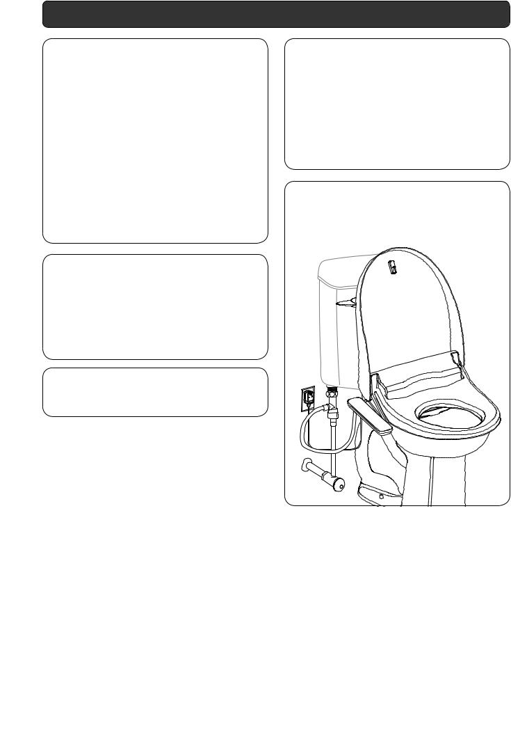
2. Product Description
This product incorporates a set of features to improve personal toilet hygiene and comfort. These features include rear cleansing, front cleansing and a seat heater as well as the required controls for these features.
This product includes a seat unit (with heated toilet seat, toilet seat lid, warm water tank, and power cord), hardware for installing the seat unit on a toilet and connecting it to the water supply and this installation and user's manual.
This product incorporates the following features:
•rear cleansing with water flow strength controls
•front cleansing with water flow strength controls
•seat heater with heat level control
•rear and front cleansing water temperature control
•seat and water temperature indicators
•rear and front nozzle self-cleaning
•stop button for rear cleansing, front cleansing
Note:
•When transporting the product, take care not to inadvertently bump or drop it.
•This product has been already inspected using tap water. A small amount of water may be detected when installing the unit; this should not be a cause for concern.
5
3. Installing This Product
Installation Requirements
Before installing this product, ensure that each of the following installation requirements are met.
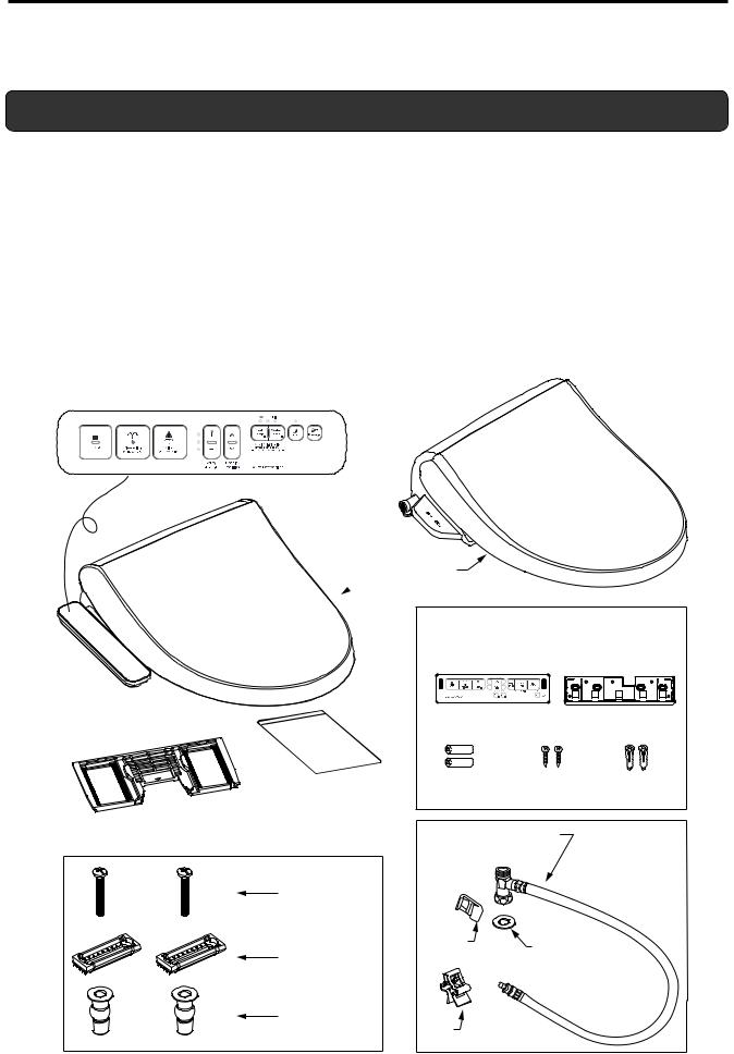
Contents
Remove the parts from the box and make sure all the parts in the parts list (below) are present. Inspect the parts carefully to make sure they are in good condition.
If any part is damaged or missing, do not install this product. Contact a customer service representative for the part(s) you need.
The following parts are included: |
FOR REMOTE VERSION ONLY: |
||
• |
Seat unit (with heated toilet seat, toilet seat lid and power cord) |
• |
Remote control |
• |
Mounting plate |
• |
Bracket |
• |
Manual |
• |
Batteries |
• |
Mounting bolts, brackets, and bushings (2 pieces each) |
• |
Wood screw |
• |
Seat unit water supply hose (with 1 clip and 1 washer) |
• |
Plastic anchors |
Side Panel
 Seat
Seat
Mounting plate
(This plate attaches to the seat unit.)
|
*Remote control unit and bracket are |
||
|
packed in the box. |
|
|
|
Remote control unit |
Bracket |
|
|
For remote control unit |
|
|
Manual |
Batteries (2) |
Wood |
Plastic |
|
screws |
anchors |
|
|
|
||
Water supply hose (w/ T-junction)
Mounting bolt |
|
|
|
|
Plastic |
Washer |
|
Bracket |
Clip |
||
|
|||
Bushing |
Clip |
|
|
|
|
6
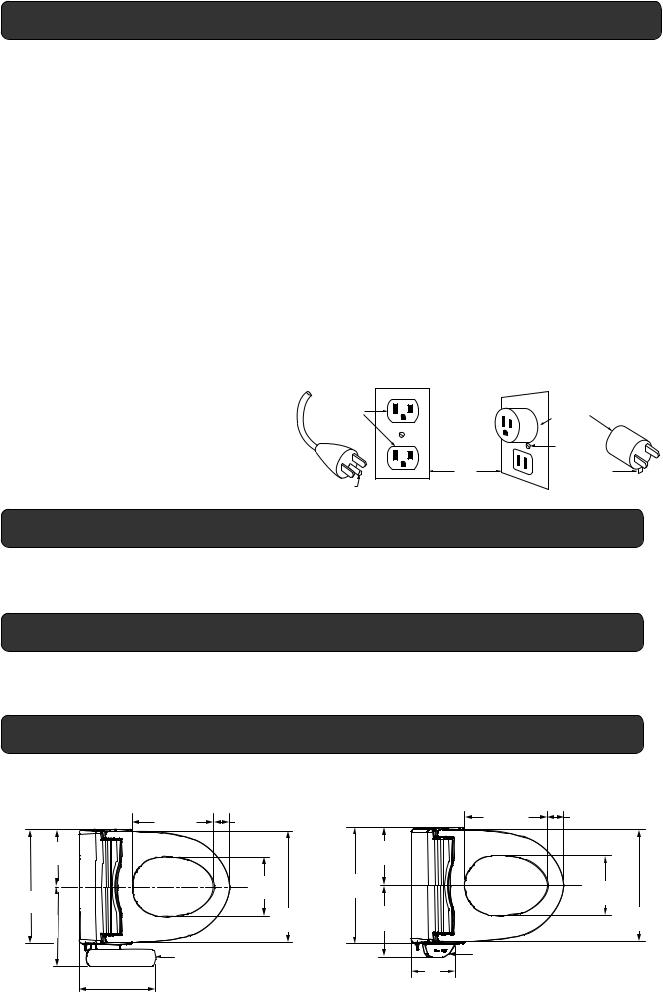
GROUNDING INSTRUCTIONS
This product should be grounded. In the event of an electrical short circuit, grounding reduces the risk of electric shock by providing an escape wire for the electric current. This product is equipped with a cord having a grounding wire with a grounding plug. The plug must be plugged into an outlet that is properly installed and grounded.
DANGER– Improper use of the grounding plug can result in a risk of electric shock.
If repair or replacement of the cord or plug is necessary, do not connect the grounding wire to either flat blade terminal. The wire with insulation having an outer surface that is green with or without yellow stripes is the grounding wire.
Check with a qualified electrician or serviceman if the grounding instructions are not completely understood, or if in doubt as to whether the product is properly grounded.
This product is for use on a nominal 120 V circuit, and has a grounding plug that looks like the plug illustrated in sketch A. A temporary adapter, which looks like the adapter illustrated in sketches B and C, may be used to connect this plug to a 2-pole receptacle as shown in sketch B if a properly grounded outlet is not available. The temporary adapter should be used only until a properly grounded outlet (sketch A) can be installed by a qualified electrician. The green colored rigid ear, lug, and the like extending from the adapter must be connected to a permanent ground such as a properly grounded outlet box cover. Whenever the adapter is used, it must be held in place by the screw.
If it is necessary to use an extension cord, use only a three wire extension cord that has a three-blade grounding plug, and
a three-slot receptacle that will accept the plug on the product. Replace or repair a damaged cord.
|
|
GROUNDING |
|
GROUNDED |
|
METHODS |
|
OUTLET |
|
|
ADAPTER |
|
|
|
METAL |
|
|
GROUNDED |
SCREW |
|
|
OUTLET |
TAB FOR |
|
|
BOX |
|
|
|
METAL SCREW |
|
|
|
|
|
GROUNDING PIN |
A |
B |
C |
Installation Location
In order to prevent damage to the electronic components, install this product at a location that minimizes the possibility of it getting wet. In extremely humid conditions, provide adequate ventilation by operating an exhaust fan or opening a window or door.
Water Supply
Use only the tap water line to supply water to this product. The use of any other type of water i.e. ground water or well water may reduce functionality of product.The tap water pressure must be 8.5 to 106.7 psi (0.06 to 0.74 MPa, 0.6 to 7.5 kgf/cm2).
Checking the Bathroom
The dimensions required for mounting this product on a toilet are shown in the figure below. Check to make sure there is sufficient space inside the bathroom and that there are no obstructions.
7-11/16" |
(195mm) |
15-3/8" |
(391mm) |
10 - 9/16" |
(269mm) |
11-1/4" |
2-3/16" |
11-1/4" |
2-3/16" |
(286mm) |
(56mm) |
(286mm) |
(56mm) |
|
|
7-11/16" |
|
|
|
(195mm) |
|
|
7-15/16" |
15-3/8" |
7-15/16" |
|
(202mm) |
(391mm) |
|
|
(202mm) |
||
|
|
|
|
|
14-7/8" |
9-1/2" |
14-7/8" |
|
(378mm) |
(241mm) |
(378mm) |
Side Panel |
Remote receiver |
|
10-9/16" |
6" |
|
(152mm) |
||
(269mm) |
7
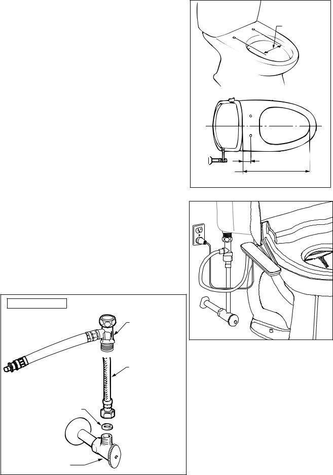
1. Measure the size of the toilet.
Depending on the size of the toilet, it may not be possible to mount this product on it.
Make sure the toilet's dimensions are as shown in the figure on the right.
2.Conditions for using water supply hose (included)
The length of the water supply hose included with this product is 37-3/8" (950 mm), but a length of 31-1/2" (800 mm) from the junction fitting to the seat unit's water supply socket is appropriate. (Refer to the figure on the right)
Installation Figure
Water supply hose (w/ T junction)
Toilet Water supply hose
Seal washer
5-1/8" to 8-1/2"
(130 to 215 mm)
|
1-1/8" (30 mm) |
17-5/16"-19-5/8" |
or more |
|
|
(440-500 mm) |
|
Water supply valve
8
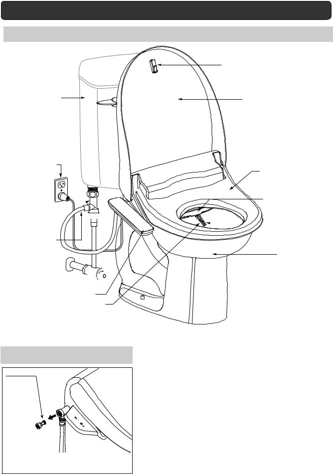
Illustrated Parts Breakdown
Overview
Toilet
Tank
Power Plug
T-Junction

Water Hose
(with T-Junction)
Water Valve

Control Panel
Nozzle (feminine cleansing)
Strainer
Strainer
*The strainer removes impurities and debris from the tap water.
Lid Bumper
Lid
Seat Sensor (built-in)
Nozzle Shutter  Seat
Seat
 Nozzle (posterior cleansing)
Bowl
9
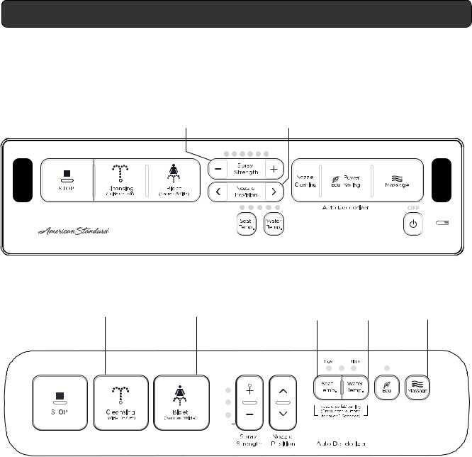
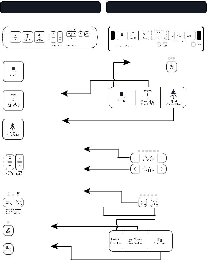
Operating Panel
Remote
SPRAY |
|
NOZZLE |
|
|
|
|
ECO |
|
POWER |
||||||
|
|
|
|
|
|
||||||||||
STRENGTH |
|
POSITION |
|
|
|
|
Power saving |
|
Controls POWER |
||||||
Adjusts Feminine |
|
There are 5 modes |
|
|
|
|
|
|
|
|
to the seat |
||||
and Posterior |
|
for nozzle position |
|
|
|
|
|
|
|
|
|
|
|
||
spray strength |
|
adjustment |
|
|
|
|
|
|
|
|
|
|
|
||
|
|
|
|
|
|
|
|
|
|
|
|
|
|
|
|
|
|
|
|
|
|
|
|
|
|
|
|
|
|
|
|
|
|
|
|
|
|
|
|
|
|
|
|
|
|
|
|
|
|
|
|
|
|
|
|
|
|
|
|
|
|
|
|
|
|
|
|
|
|
|
|
|
|
|
|
|
|
|
|
|
|
|
|
|
|
|
|
|
|
|
|
|
|
|
|
|
|
|
|
|
|
|
|
|
|
|
|
|
|
|
|
|
|
|
|
|
|
|
|
|
|
|
|
|
|
|
|
|
|
|
|
|
|
|
|
|
|
|
|
|
|
|
|
|
|
|
|
|
|
|
|
|
|
|
|
|
|
|
|
|
|
|
|
|
|
|
|
|
|
|
|
|
|
|
|
|
|
|
|
|
|
|
|
|
|
|
|
|
|
|
|
|
|
|
STOP |
|
CLEANSING |
|
|
BIDET |
|
|
|
SEAT |
|
|
WATER |
|
MASSAGE |
||
Stops cleansing |
|
Use for Posterior |
|
Use for Feminine |
|
|
TEMPERATURE |
|
TEMPERATURE |
|
Massage cleaning |
|||||
functions |
|
Cleansing. |
|
|
Cleansing. |
|
|
Adjusts seat |
|
Adjusts water |
|
(only for posterior) |
||||
|
|
|
|
|
|
|
|
|
|
temperature |
|
|
temperature |
|
|
|
|
|
|
|
|
|
|
|
|
|
|
|
|
|
|
|
|
Side Panel
|
|
|
|
|
|
|
|
|
|
|
|
|
|
|
|
|
|
|
|
|
|
|
|
|
|
|
|
|
|
|
|
|
|
|
|
|
|
|
|
|
|
|
|
|
|
|
|
|
|
|
|
|
|
|
|
|
|
|
|
|
|
|
|
|
|
|
|
|
|
|
|
|
|
|
|
|
|
|
|
|
|
|
|
|
|
|
|
|
|
|
|
|
|
|
|
|
|
|
|
|
|
|
|
|
|
|
|
|
|
|
|
|
|
|
|
|
|
|
|
|
|
|
|
|
|
|
|
|
|
|
|
|
|
|
|
|
|
|
|
|
|
|
|
|
|
|
|
|
|
|
|
|
|
|
|
|
|
|
|
|
|
|
|
|
|
|
|
|
|
POWER |
|
|
SPRAY |
|
|
NOZZLE |
|
|
ECO |
|||||||
Controls POWER |
|
|
STRENGTH |
|
POSITION |
|
|
Power saving |
||||||||
to the seat and |
|
|
Adjusts Feminine |
|
There are 5 modes |
|
|
|
|
|||||||
stops cleansing |
|
|
and Posterior |
|
for nozzle position |
|
|
|
|
|||||||
functions |
|
|
spray strength |
|
adjustment |
|
|
|
|
|||||||
|
|
|
|
|
|
|
|
|
|
|
|
|
|
|
|
|
10
Installation
1. Required tools
Have the following tools for installing this product: adjustable end wrench, Phillips head screwdriver, flat-blade screwdriver.
2.Install the junction fitting
1)Close the toilet water shutoff valve fully.
2)Flush the toilet and empty all the water from the tank.
3)Place a wash bowl or other container underneath the tank water supply hose. Then loosen the box nut on the tank inlet side and remove it.
CAUTION
•Be careful not to damage the water supply hose.
4)Place the packing in the junction fitting box nut and connect the tank inlet to the junction fitting.
CAUTION
•Do not overtighten the nut.
5)Insert the packing in the tank water supply hose box nut and connect the tank water supply hose to the junction fitting.
CAUTION
• Do not overtighten the nut.
Bowl Cock Side
Box Nut
Tank Water
Supply Hose
Water Shutoff Valve


 Close
Close
Installation
Figure
Packing |
Tank Inlet |
|
|
Junction |
Box Nut |
|
|
Fitting |
|

 Packing
Tank Water
Supply Hose
Water Shutoff
Valve

11
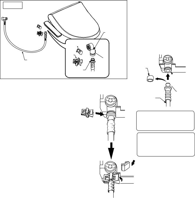
3. Installation of water supply hose to the bidet
Installation
Figure
Water supply joint
Plastic
Clip
Clip
Water supply hose
O-ring
3) Insert the attachment clip onto the water supply hose to attach it to the bidet and water supply connection socket.
*The attachment clip can be attached in any direction.
4) Bend the clip end and firmly clip together both the feeding hose for the bidet and the feeding socket. After you install the clip, twist it in both directions to verify that it is firmly attached, then attach the final attachment clip over the primary clip to secure in place.
5) Insert the clip until you feel the clip edge click.
*If not firmly inserted, it may cause water leaks
1)Remove the protective cover from the end of the water supply hose, and pull out the cap from the water supply connection socket.
2)Connect the water supply hose for the bidet to the water supply connection socket.
WATER SUPPLY
CONNECTION SOCKET
Protective
Cover
 Water supply
  socket
Water supply |
O-ring |
|
hose for |
||
|
||
the seat |
|
CAUTION
• Be careful not to damage the O-ring.
*A damaged O-ring may cause water to leak.
CAUTION
• Firmly insert the clip.
*If the clip is not firmly inserted, it may cause water leaks.
12
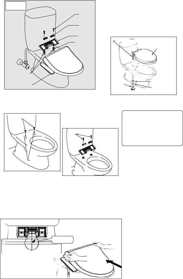
4. Installation of the bidet |
|
Installation |
(1) Remove the existing seat. |
Figure |
1) Remove the nuts from the seat |
Body |
|
mounting |
mounting bolts, the slip washers, |
bolt |
and rounded packing. |
Bracket |
2) Raise the seat and remove it by |
Mounting |
lifting the seat mounting bolts. |
|
|
plate |
|
Bushing |
Seat mounting bolts |
|
|
|
Existing seat |
Seat |
|
mounting hole |
|
E-bidet |
Rounded packing |
Nut |
|
|
Slip washer |
Loosen
(2) Install the slide plate onto the seat.
1) Insert the bushings into |
2) Insert the mounting |
|
the seat mounting holes. |
bracket into the mounting |
|
|
plate and use the mounting |
|
Bushings |
bolts to attach the slide |
References |
plate to the seat. |
||
|
|
• Some toilet seats may require |
|
Mounting bolts |
different methods of removal that |
|
differ from our explanation. |
|
|
for the toilet |


 Mounting
brackets
 Mounting plate
Seat mounting holes
(3)Install the bidet.
1)Place the bidet on the toilet and align the seat to the mounting plate.
2)Slightly raise the front side of the bidet, slide it until the slide plate is fully inserted, and then press the locking lever to secure the bidet.
Center aligned |
13 |
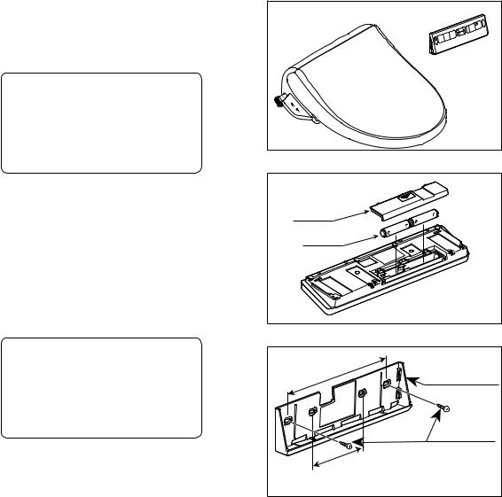
5.Install the remote control unit
* For Remote Version Only
(1) Open the back cover of the remote control unit and insert the 2 size AA batteries.
CAUTION
• Insert each battery so its positive pole touches a positive connector in the battery compartment and its negative pole touches a negative connector.
(2) Position the bracket on the wall in the location you chose for the remote control unit. Mark the
location of the mounting holes on the wall. Fasten the bracket to the wall, drilling holes and using the fasteners appropriate for the wall material, as described below.
CAUTION
• Leave enough space above the top of the remote control unit to allow the unit to be removed and replaced.
If mounted in plywood paneling 0.20 in. (5 mm) or greater in thickness:
Fasten the bracket to the wall with the mounting screws.
Back Cover
Battery
200mm |
Bracket |
|
|
|
Mounting Screw |
100mm |
|
14
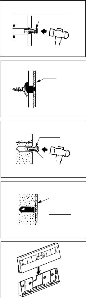
If mounted either in plywood paneling 0.20 in. (5 mm) or less in thickness or in gypsum board:
1) In plywood paneling, drill holes with a diameter of 0.24 in. (6 mm); in gypsum board, drill holes with a diameter of 0.20 in. (5 mm):
2)Using a hammer, gently drive the plastic anchors into the holes.
3)Fasten the bracket securely to the anchors using mounting screws. As you tighten the screws, they are hard to turn at first, then gradually get easier to turn, and then are hard to turn again.
If mounted in concrete:
1)Drill holes with a diameter of 0.24 in. (6 mm) and a depth of approximately 1.30 in. (33 mm).
2)Using a hammer, gently drive the plastic anchors into the holes.
3)Fasten the bracket securely to the anchors using mounting screws.
(3) Align the remote control unit with the bracket and then push it down onto the bracket.
Plywood paneling : 0.24 in. (6 mm)-dia. Gypsum board : 0.20 in. (5 mm)-dia.
Plastic Anchor
Bracket

 Mounting Screw
1.30 in. |
Plastic Anchor |
(33 mm) |
|
0.24 in.
(6 mm)-dia.
Bracket


 Mounting Screw
Remote
Bracket
15

Operational Check
Follow the procedure below after the installation work has been completed.
1. Insert the power plug into the outlet.
Confirm that the LED on the seat unit is lit.
Power plug
Side Panel Version |
Remote Control Version |
2.Check the Feminine and Posterior cleansing spray.
(1)Check the cleansing operation.
1)With your forearm resting on the toilet seat, press the cleansing button.
The shower automatically stops two minutes after the switch is turned on.
2)When the nozzle extends, cover the tip of the nozzle with your hand to catch the spray.
3)Press the STOP button to stop the cleansing spray.
(2)Perform the same check using the
front cleansing spray function.
Press here on seat
Remote
SPRAY |
|
NOZZLE |
|
|
|
|
|
ECO |
|
POWER |
|||||||
|
|
|
|
|
|
|
|||||||||||
STRENGTH |
|
POSITION |
|
|
|
|
|
Power saving |
|
Controls power |
|||||||
Adjusts feminine |
|
There are 5 modes |
|
|
|
|
|
|
|
|
|
to the seat |
|||||
and posterior |
|
for nozzle position |
|
|
|
|
|
|
|
|
|
|
|
|
|||
spray strength |
|
adjustment |
|
|
|
|
|
|
|
|
|
|
|
|
|||
|
|
|
|
|
|
|
|
|
|
|
|
|
|
|
|
|
|
|
|
|
|
|
|
|
|
|
|
|
|
|
|
|
|
|
|
|
|
|
|
|
|
|
|
|
|
|
|
|
|
|
|
|
|
|
|
|
|
|
|
|
|
|
|
|
|
|
|
|
|
|
|
|
|
|
|
|
|
|
|
|
|
|
|
|
|
|
|
|
|
|
|
|
|
|
|
|
|
|
|
|
|
|
|
|
|
|
|
|
|
|
|
|
|
|
|
|
|
|
|
|
|
|
|
|
|
|
|
|
|
|
|
|
|
|
|
|
|
|
|
|
|
|
|
|
|
|
|
|
|
|
|
|
|
|
|
|
|
|
|
|
|
|
|
|
|
|
|
|
|
|
|
|
|
|
|
|
STOP |
|
CLEANSING |
|
|
BIDET |
|
|
|
SEAT |
|
|
WATER |
|
MASSAGE |
||
Stops cleansing |
|
Use for posterior |
|
Use for feminine |
|
|
TEMPERATURE |
|
TEMPERATURE |
|
Massage cleaning |
|||||
functions |
|
cleansing. |
|
|
cleansing. |
|
|
Adjusts seat |
|
Adjusts water |
(only for posterior) |
|||||
|
|
|
|
|
|
|
|
|
|
temperature |
|
|
temperature |
|
||
Side Panel
|
|
|
|
|
|
|
|
|
|
|
|
|
|
|
|
|
|
|
|
|
|
|
|
|
|
|
|
|
|
|
|
|
|
|
|
|
|
|
|
|
|
|
|
|
|
|
|
|
|
|
|
|
|
|
|
|
|
|
|
|
|
|
|
|
|
|
|
|
|
|
|
|
|
|
|
|
|
|
|
|
|
|
|
|
|
|
|
|
|
|
POWER |
|
|
SPRAY |
|
|
NOZZLE |
|
ECO |
||||
Controls power |
|
|
STRENGTH |
|
POSITION |
|
Power saving |
|||||
to the seat and |
|
|
Adjusts feminine |
|
There are 5 modes |
|
|
|
||||
stops cleansing |
|
|
and posterior |
|
for nozzle position |
|
|
|
||||
functions |
|
|
spray strength |
|
adjustment |
|
|
|
||||
|
|
|
|
|
|
|
|
|
|
|
|
|
16
OPERATIONAL MANUAL |
|
TABLE OF CONTENTS |
|
Additional Important Information..................................................................................... |
18 |
Product Functions................................................................................. |
19 |
Side Panel / Remote Control........................................................................................... |
19 |
Preparations Before Use................................................................................................ |
20 |
How to Use the Basic Functions.................................................................................... |
21 |
How to Use the Convenient Functions........................................................................... |
24 |
Maintaining This Product...................................................................... |
28 |
Cleaning the Seat Unit................................................................................................... |
28 |
Cleaning the Nozzles..................................................................................................... |
28 |
Changing the Nozzle Tip................................................................................................ |
28 |
Cleaning & Maintenance of the Deodorizing Screen..................................................... |
29 |
Cleaning the Inlet Strainer.............................................................................................. |
30 |
Cleaning Areas Covered by the Toilet Seat Lid & Unit.................................................... |
31 |
Change Batteries for the Remote Control....................................................................... |
32 |
Troubleshooting.................................................................................... |
33 |
Specifications........................................................................................ |
35 |
Warranty information & After-sales Support....................................... |
36 |
17
Additional Important Information
•The capacity of the warm water tank is 0.88 L.
Water temperature gradually drops when rear cleansing or front cleansing is used. If the water drops below a comfortable temperature, press the stop button and wait about 3 minutes for the water to reheat.
•The water temperature range is preset to the following temperatures:
Low: Approx. 90 °F (32 °C), Medium: Approx. 93 °F (34 °C), High: Approx. 97 °F (36 °C).
It takes approximately 10 minutes to heat cold water (at about 41 °F [5 °C]) to the appropriate temperature (about 100 °F [38 °C]).
This product is designed to use the tap water pressure to extend the nozzles and spray water through them. When the tap water pressure is extremely low, the nozzles may not spray water at all when the water pressure is set to the lowest setting. If this occurs, adjust the Spray Strength.
When the toilet is new, a slight odor may come from the deodorizer. This will go away in a short time.
Before and after cleansing and when the water temperature adjustment button is pressed, etc., water is sprayed from the nozzle. This occurs by design and is not a cause for concern.
If water sprays while under any other configuration, or sprays constantly, close the water shutoff valve and remove the power plug from the wall outlet. Then, contact cutomer service.
This product is equipped with a seat sensor that prevents the water from spraying if nobody is sitting on the toilet seat. This prevents activation if the Bidet button is pressed when the toilet seat is unoccupied.
18
Product Functions
Side Panel |
Remote |
STOP |
STOP |
POWER |
|
|
|
Power On/Off |
Stop function |
Power On/Off |
Stop function |
|
|
CLEANSING
For posterior cleansing only.
Press twice for oscillating function.
BIDET
For feminine cleansing.
Press twice for oscillating function.
Press twice for super oscillating function.
SPRAY STRENGTH
Adjusts spray strength for cleansing and bidet settings.
NOZZLE POSITION
Nozzle position adjustment for optimal cleansing.
SEAT TEMPERATURE
Adjust warm seat temperature
WATER TEMPERATURE 
Adjust warm water temperature
ECO
Power saving Mode
MASSAGE
Massage cleaning (only for posterior)
 NOZZLE CLEANING
Nozzle self-cleaning.
FOR DETAILED FUNCTIONS SEE OPERATION SECTION
19
 Loading...