


INSTALLATION
INSTRUCTIONS
TU41550X
Portsmouth® TU42050X
Pressure Balancing
Bath and Shower Trim Kit
Thank you for selecting American Standard...
the benchmark of fine quality for over 140 years.
To ensure that your installation proceeds smoothly-please read these instructions carefully before you begin.
For use with shower heads rated at 4.9 L/min (1.3 gpm) or higher.
H
Off
TU41550X
RECOMMENDED TOOLS
|
|
Phillips Screwdriver |
|
Plumbers’ Putty |
Teflon Tape |
Flat Blade Screwdriver |
Adjustable Wrench |
or Caulking |
|
|
|
H
Off
TU42050X
Channel Locks
ROUGHING-IN DIMENSIONS |
1 |
CARTRIDGE INSTALLATION |
|
|
|
|
|
||
• To assure proper positioning in relation to wall. |
|
|
|
|
Note roughing-in dimensions. |
|
• Remove PLASTER GUARD (6) |
|
|
|
1-5/8" TO 3" |
(Keep it installed for thin wall Installation). |
|
|
FINISHED WALL |
(41mm TO 76mm) |
• Remove BONNET NUT (1) by unthreading it |
|
|
1/2" NPT |
|
|||
|
Counter clockwise. Remove test CAP (2). |
|
||
|
(12,7 mm) NPT |
|
||
3-3/4" REF. |
|
• Remove PROTECTIVE HOUSING (3) from |
|
|
|
CARTRIDGE (4). Install with “UP” text on top. |
|
||
(95 mm) |
|
|
||
|
|
|
|
|
|
|
• Reinstall BONNET NUT (1) onto VALVE BODY (5) |
|
|
|
OPTIONAL TO |
and tighten firmly with 12 Nm or 9 lbs/ft. |
|
|
|
FINISHED FLOOR |
|
|
|
7-1/4" |
USUALLY BETWEEN |
|
|
|
(184 mm) |
65'' AND 78'' |
|
|
|
7-1/2" REF. |
|
|
UP |
|
(191 mm) |
2-3/4" MAX. (69 mm) |
5 |
|
|
|
|
|
||
|
1-3/4" MIN. (45 mm) |
|
|
|
|
6-3/8" |
1 |
|
|
|
(163 mm) |
|
|
|
74" FOR HEAD CLEARANCE |
|
3 |
|
|
|
|
|
|
|
(188 cm) |
7-5/8" DIÁM. |
|
|
|
|
UP |
4 |
6 |
|
|
(195 mm) |
|||
18" OPTIONAL |
|
|
|
|
(45,7 cm) |
|
2 |
|
|
|
|
|
|
|
|
1-1/2" REF. |
|
|
|
|
(38 mm) REF. |
|
|
|
|
1/2" COPPER |
|
|
|
5-1/8" REF. |
4" (102 mm) |
|
|
|
(130 mm) REF. |
|
|
|
|
|
|
|
|
|
|
TOP OF TUB RIM |
NOTE: Specified tightening torque |
|
|
BOTTOM OF TUB |
of BONNET NUT (1) is critical to |
|
|
|
|
|
assure sealing function. |
|
|
Product names listed herein are trademarks of AS America, Inc. |
- 1 - |
M965927 (8/18) |
|
© AS America, Inc. 2018 |
|||
|
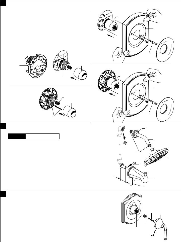
2 STANDARD WALL INSTALLATION
• Figure 1. Remove plaster guard from valve. Push CAP (1) |
|
|
|
|||
over VALVE CARTRIDGE (2) until seated against stop. |
|
1 |
|
|||
• Figure 2. Push ESCUTCHEON (3) onto CAP (1) and attach |
|
|
||||
|
|
|
||||
to valve body with LONG SCREWS (4). |
|
|
|
|
||
THIN WALL INSTALLATION |
|
|
|
3 |
|
|
|
|
|
|
|
||
• Figure 1a. Push CAP (1) over VALVE CARTRIDGE (2) until |
|
|
|
|||
seated against stop. |
|
|
|
|
|
|
• Figure 2a. Push ESCUTCHEON (3) onto CAP (1) and attach |
|
|
H |
|||
to valve body with LONG SCREWS (4). |
|
|
|
|
||
|
|
|
|
|
4 |
C |
|
|
|
|
Figure 2. |
|
Off |
PLASTER |
|
|
UP |
|
|
|
|
|
|
|
|
||
GUARD |
|
|
1 |
|
|
|
|
|
|
|
|
|
|
Figure 1. |
2 |
|
|
1 |
|
|
|
|
|
|
|
||
|
|
|
|
|
3 |
|
|
|
UP |
2 |
|
|
|
|
|
|
1 |
|
|
|
|
|
|
|
|
|
H |
|
|
4 |
|
|
4 |
C |
Figure 1a. |
|
Figure 2a. |
|
Off |
||
|
|
|
|
|||
3 INSTALL, TUB SPOUT, SHOWER HEAD, |
|
3 |
|
|||
SHOWER ARM WITH FLANGE |
|
|
|
|||
CAUTION |
Protect finish on SHOWER HEAD |
|
|
|
|
|
and TUB SPOUT when installing. |
|
|
4 |
|
||
|
|
|
|
|
|
|
Note: Apply sealant or Teflon Tape to shower arm. |
|
1 |
|
|||
• Remove PIPE PLUG and CAP (1, 2) from |
|
|
||||
|
APPLY |
|
||||
shower pipe and tub filler pipe. |
|
|
|
|||
|
|
SEALANT |
|
|||
• Install SHOWER ESCUTCHEON (3) onto SHOWER ARM (4). |
|
OR TEFLON |
5 |
|||
|
TAPE TO |
|||||
Apply sealant or Teflon tape to threads on both ends of |
|
THREADS |
|
|||
|
2 |
|
||||
SHOWER ARM (4) and thread longer leg of SHOWER ARM (4) |
|
|
||||
|
|
|
||||
into shower elbow. Thread SHOWER HEAD (5) onto SHOWER ARM (4). |
|
|
||||
• Install SLIP-ON TUB SPOUT (6). Tighten SET SCREW (7) |
1-3/4" |
|
|
|||
awith HEX WRENCH supplied |
|
|
6 |
|
||
|
|
(44 mm) |
|
|||
Important: Do not overtighten Set Screw. |
|
|
||||
|
|
|
|
|||
|
|
|
|
|
HEX WRENCH |
|
4INSTALL HANDLE
•Hold ADAPTER (1) onto VALVE STEM (2) and install ADAPTER SCREW (3) through ADAPTER (1) into VALVE STEM (2). Tighten ADAPTER SCREW (3) to secure ADAPTER (1).
•Install HANDLE BASE (4) onto ADAPTER (1). Tighten SET SCREW (5) with HEX WRENCH (6) supplied.
- 2 -
|
H |
|
3 |
C |
4 |
Off
1 2 5 

6
M965927 (8/18)
 Loading...