

Page 1
Installation Instructions
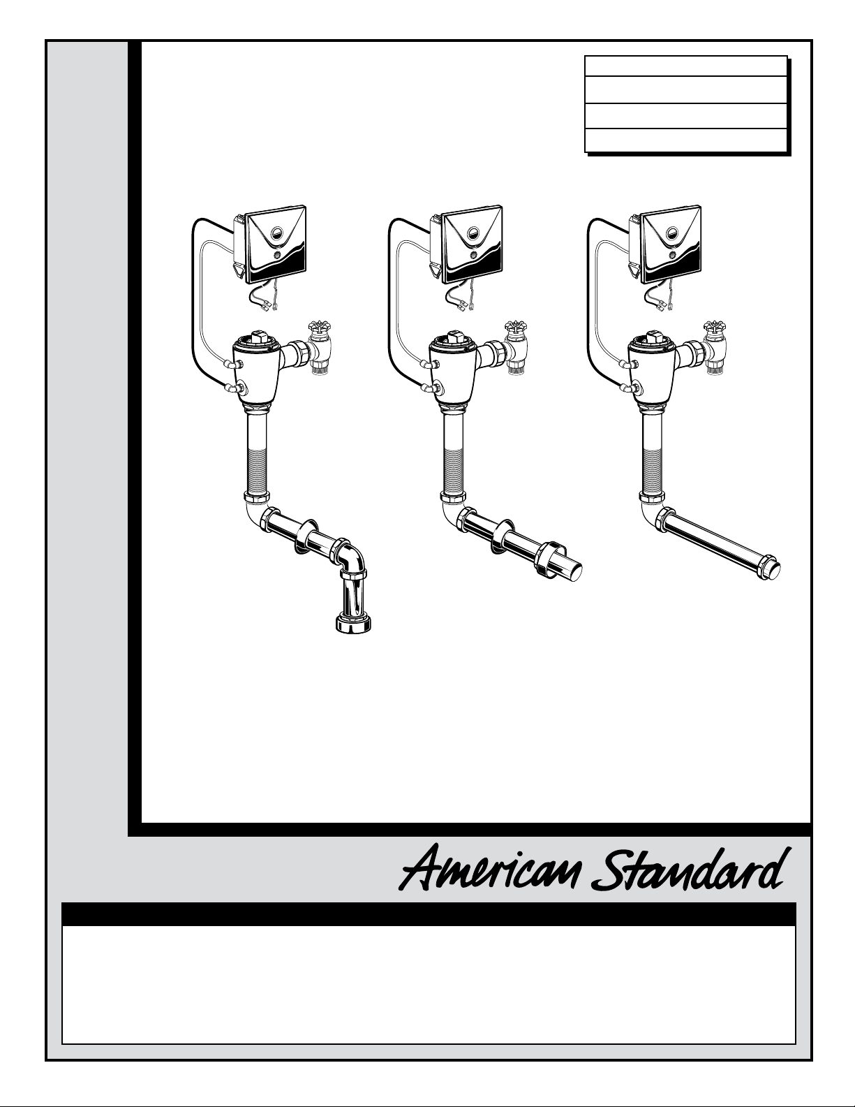
SELECTRONIC™
PROXIMITY TOILET
CONCEALED FLUSH VALVE
1.28 & 1.6 GPF
MODEL NUMBERS
6065.22X
6067.22X
6068.22X
6065.26X
6067.26X
6068.26X
Concealed Flushometer
for 1-1/2" Top or Back Spud Bowls
CLOG RESISTANT
• Self-cleaning piston valve prevents clogging and reduces maintenance.
ONE SENSOR FITS ALL
• Only 1 sensor for entire Selectronic™ line of faucets, urinals, and
ush valves.
Certified to comply with ASME A112.19.2M
© 2010 AS America, Inc.
Installation Instructions
M968550 REV. 1.5
NOTE TO INSTALLER: Please give this manual to the customer after installation.
To learn more about American Standard Faucets visit our website at: www.americanstandard-us.com
or U.S. customer's e-mail us at: faucetsupport@americanstandard.com
For Parts, Service, Warranty or other Assistance,
please call
1-800-442-1902 (In Canada: 1-800-387-0369)
• Range can be adjusted manually or with optional remote control.
• Sensor Features Low Battery Indicator.
(In Toronto Area only: 1-905-3061093)
(In Toronto Area only: 1-905-3061093)
Page 2
Thank you for selecting American-Standard...the benchmark of fine quality for over 100 years. To ensure that your
Installation Instructions
installation proceeds smoothly--please read these instructions carefully before you begin.
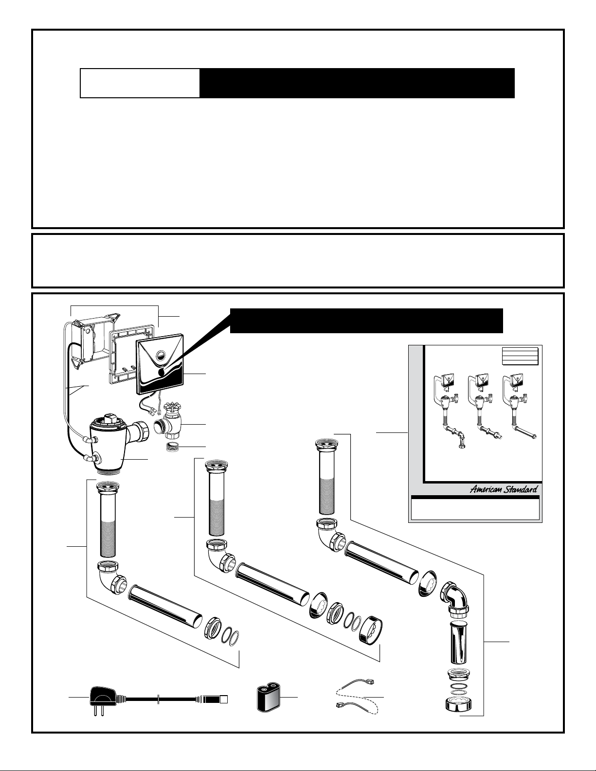
UNPACKING
All American Standard Products Are Water Tested At Our Factory.
Some Residual Water May Remain In The Valve During Shipping.
1. Remove the Flush Valve items from the carton. The illustration below shows all items after
they have been removed from the carton. Some items may be packaged partially assembled to
other items.
1. Flush Valve Assembly
2. Electrical Box
3. Cover Plate with Sensor
4. Supply Stop
5. Sweat Solder Adapter
6. Manual Override Hoses
7a. Vacuum Breaker Flush Connection
(Wall-Mount Back Spud)
7b. Vacuum Breaker Flush Connection
(Floor-Mount Back Spud)
CARE INSTRUCTIONS FOR CHROME PLATED ITEMS:
DO: SIMPLY RINSE THE PRODUCT CLEAN WITH CLEAR WATER. DRY WITH A SOFT COTTON FLANNEL CLOTH.
DO NOT: DO NOT CLEAN THE PRODUCT WITH SOAPS, ACID, POLISH, ABRASIVES, HARSH CLEANERS, OR A
CLOTH WITH A COARSE SURFACE.
2
P
TO
DO NOT REMOVE PROTECTIVE FILM FROM SENSOR
EYE UNTIL INSTALLATION IS COMPLETE.
7c. Vacuum Breaker Flush Connection
(Top Spud)
8a. AC Power Supply [Model# 6067]
8b. DC Power Supply
8c. 10’ Extension Wire for Multi-AC
9. Installation Instructions
SELECTRONIC™
PROXIMITY TOILET
CONCEALED FLUSH VALVE
1.28 & 1.6 GPF
MODEL NUMBERS
6065.22X
6067.22X
6068.22X
6065.26X
6067.26X
6068.26X
3
6
7a
8a
1
7b
4
5
9
8b 8c
Concealed Flushometer
for 1-1/2" Top or Back Spud Bowls
CLOG RESISTANT
• Self-cleaning piston valve prevents clogging and reduces maintenance.
ONE SENSOR FITS ALL
• Only 1 sensor for entire Selectronic™ line of faucets, urinals, and
ush valves.
Certified to comply with ASME A112.19.2M
© 2009 AS America, Inc.
Installation Instructions
M968550 REV. 1.5
NOTE TO INSTALLER: Please give this manual to the customer after installation.
To learn more about American Standard Faucets visit our website at: www.americanstandard-us.com
or U.S. customer's e-mail us at: faucetsupport@americanstandard.com
For Parts, Service, Warranty or other Assistance,
1-800-442-1902 (In Canada: 1-800-387-0369)
please call
• Range can be adjusted manually or with optional remote control.
• Sensor Features Low Battery Indicator.
(In Toronto Area only: 1-905-3061093)
(In Toronto Area only: 1-905-3061093)
7c
M968550 REV. 1.5
1
Page 3
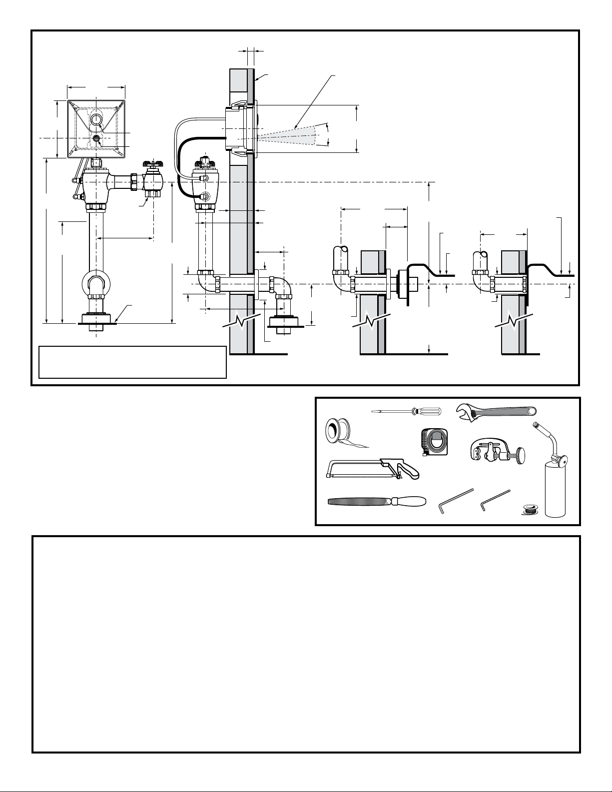
Fig. 1
Roughing-in Dimensions
160mm
(6-1/4)
160mm
(6-1/4)
OVERRIDE
BUTTON
SENSOR
25mm (1) MAX.
FINISHED WALL
TOP SPUD
TOILET
MAXIMUM
DETECTION ZONE
400mm-800mm
(15-3/4 TO 31-1/2)
127X127mm
(5X5 CUTOUT
15˚
FOR BOX)
GENERAL DESCRIPTION:
SELECTRONIC™
PROXIMITY TOILET
FLUSH VALVE
Concealed Flushometer
for 1-1/2" Spud Fixtures
Exclusive, self cleaning piston-type flush
valve with proximity operation and manual
override. Operates on DC (batt e r y)or
AC power. Recommended operating
pressure 25psi (flowing) to 80 psi (static).
Can install left or right-handed. Detection
Zone can also be adjusted manually, or
with optional remote control.
406mm
(16)
*
-C-L-
152mm
(6) MIN.
-C-L-
115mm-134mm
(4-1/2 TO 5-1/4)
SUPPLY
DN 25mm
(1) I.P.S.
403 TO 441mm
(15-7/8) MIN. TO
(17-3/8) MAX.
TOP SPUD
TOILET
51mm
(2)
483mm
(19) MAX.
*Note: The Critical Line (-C-L-) on Vacuum
Breaker must typically be 6
" (152mm) min.
above fixture. Consult Codes for details.
RECOMMENDED TOOLS; Fig. 2
1.
Teflon Tape
2.
Flat Blade Screwdriver
3.
Adjustable Wrench
4.
Tape Measure
5.
Hacksaw
6.
Tubing Cutter
7.
File
8.
For Sweat Connection; Solder and Torch
9.
2.5mm Hex Wrench
10.
1.5mm Hex Wrench
WALL THICKNESS
51mm (2)
+ WALL THICKNESS
73 TO 137mm
(2-7/8)MIN. TO
(5-3/8) MAX.
127mm
(5) MAX.
71mm
(2-3/4) DIA.
51mm
(2)
Fig. 2
EXPOSED BACK
SPUD TOILET
432mm
(17 MAX.)
73 TO 111mm
(2-7/8 TO
4-3/8)
1
289 TO 403mm
(11-3/8 MIN. TO
15-7/8 MAX.)
TOP OF
FIXTURE
19mm
(3/4.)
*FOR LOCATION OF INLET
SUPPLY ON BACK INLET
FIXTURES,REFER TO FIXTURE
BEING INSTALLED
FOR CORRECT HEIGHT FROM
FINISHED FLOOR
2
10'
4
CONCEALED BACK
SPUD TOILET
292mm
(11-1/2) MAX.
51mm
(2)
3
TOP OF
FIXTURE
6
5
8
7910
19mm
(3/4.)
PRIOR TO INSTALLATION
Note: Prior to installing the Selectronic™Flush Valve
the following items must be installed.
1. Water Closet
2. Drain line
3. Water supply line
IMPORTANT:
• All plumbing must be installed in accordance with
applicable codes and regulations.
• Water supply lines must be sized to provide an
adequate volume of water for each fixture.
• Flush all water lines prior to operation (See Step 4). Dirt
and debris can cause flush valve to run continuously.
• With the exception of Supply Stop Inlet, DO NOT use pipe
sealant or plumbing grease on any valve component or
coupling!
• Protect the chrome or special finish on chrome plated
items.
DO NOT USE toothed tools on finished surfaces to install or
service these valves. Also see “Care and Cleaning” section
of this manual.
• This product contains mechanical and/or electrical
components that are subject to normal wear. These
components should be checked on a regular basis and
replaced as needed to maintain the valve’s performance.
M968550 REV. 1.5
2
Page 4
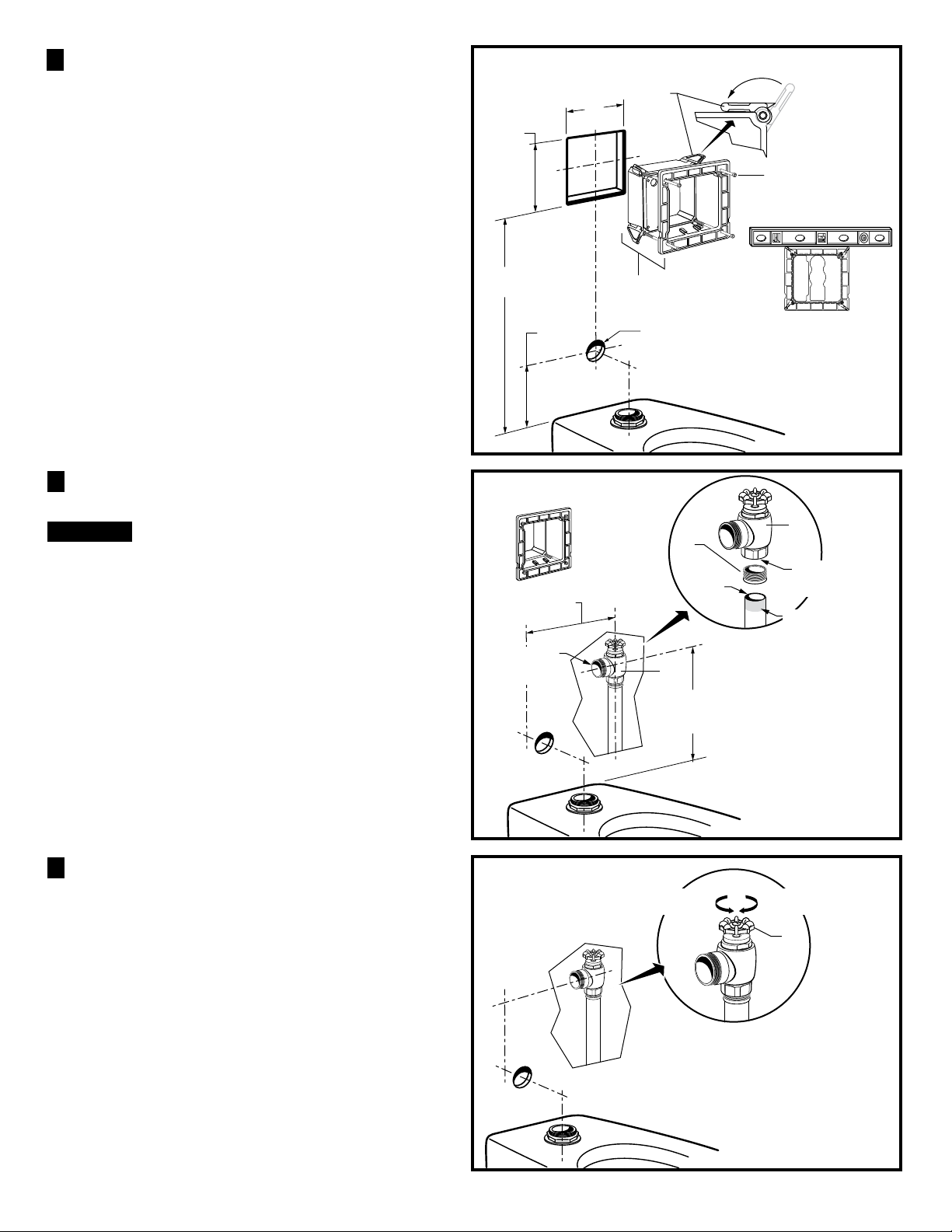
INSTALL ELECTRICAL BOX
1
ASSEMBLY; Fig. 3
1. Cut a 127x127mm (5"x 5") opening in finished wall for
ELECTRICAL BOX (1) at the deminsion shown in Fig.3.
Fig.3 (TOP SPUD FIXTURE ILLUSTRATED)
2
127mm
(5)
127mm
(5)
2. Rotate the 4 MOUNTING TABS (2) flat against the
electrical box. Holding the MOUNTING TABS (2) in
position install the ELECTRICAL BOX (1) into the opening.
Make sure the MOUNTING TABS (2) are behind the wall.
3. Tighten the the 4 MOUNTING SCREWS (3) until the
ELECTRICAL BOX (1) is almost secure in the wall.
Before tighting fully rest a level at the top edge of the
ELECTRICAL BOX (1) and make sure the box is level,
then tighten fully. Fig. 3a.
4. *Cut a 2" hole for supply to fixture at deminsion shown.
INSTALL SWEAT SOLDER
2
ADAPTER; Fig. 4
CAUTION
Note: Control stop inlet is 1" IPS. For optional sweat
connection, install Sweat Solder Adapter (1) (Supplied)
for 1" copper pipe supply line. Fig. 4.
1. Clean the end of the supply pipe. Push the threaded
ADAPTER (1) on until it is seated against the internal
stop. Sweat the ADAPTER (1) to the pipe.
2. From behind the wall install the CONTROL STOP (2)
to the water supply line with the outlet positioned as
required.
Turn water supplies off
before beginning
406mm
(16 REF.)
127mm
(5 MAX.)
Fig. 4
O
T
115mm-134mm
(4-1/2 TO 5-1/4)
CONTROL
STOP
OUTLET
TOP
3
Fig. 3a
TOP
1
*FOR HOLE LOCATION OF
SUPPLY ON BACK INLET
FIXTURES, REFER TO FIXTURE
BEING INSTALLED FOR CORRECT
HEIGHT FROM FINISHED FLOOR
P
2
1
FILE
EDGES
CONTROL STOP
DN 25mm
(1" I.P.S.)
CLEAN & SOLDER
TO ADAPTER (1)
2
403 TO 441mm
(15-7/8 MIN. TO
17-3/8 MAX.)
3. Support piping as required.
FLUSH OUT SUPPLY LINES; Fig. 5
3
1. Open SUPPLY STOP (1).
3. Turn on water supply to flush line of any debris or
sediment.
4. Close SUPPLY STOP (1) and turn off water supply line.
Fig. 5
3
COUNTER-CLOCKWISE
OPENS CONTROL STOP
CLOCKWISE CLOSES
CONTROL STOP
1
M968550 REV. 1.5
Page 5
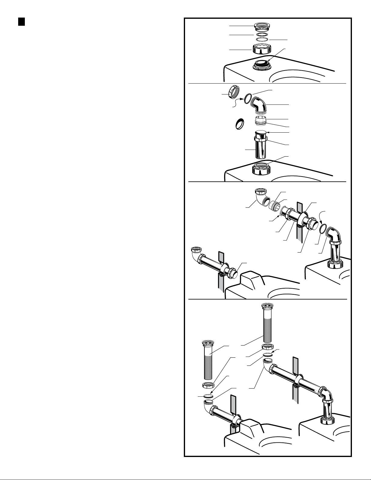
4 INSTALL VACUUM BREAKER AND
4
3
FLUSH CONNECTIONS; Fig. 6
1. Place the SPUD FLANGE (1) over the spud on the
Fixture. Fig. 6.
2. Thread SPUD COUPLING NUT (2) onto Spud. Make
sure SEAL WASHER (4) and FRICTION WASHER (3)
are installed. Do not tighten fully. Fig. 6.
Fig. 6
2
3
1
4
1-1/2" TOP SPUD
3. Remove the COUPLING NUTS (6, 6a) from the
CHROME ELBOW (5). Make sure you have a TAPERED
RUBBER WASHER (7), PLASTIC SUPPORT (8) and
SQUARE SEAL WASHER (9). Fig. 6a.
4. Install the SQUARE SEAL WASHER (9) onto the
PLASTIC SUPPORT (8) if not already installed. Insert
the PLASTIC SUPPORT (8) into the DOWN TUBE (10).
Slide the COUPLING NUT (6) onto the DOWN TUBE
(10). Connect the COUPLING NUT (6) to the
CHROME ELBOW (5) and tighten fully. Insert the
DOWN TUBE (10) with CHROME ELBOW (5) into the
SPUD COUPLING NUT (2) and push it down. Do not
tighten fully. Fig. 6a. Note: If center line of ELBOW
(5) cannot be adjusted to line up with hole in wall,
then cut the DOWN TUBE (10) as required.
5. Measure and cut the HORIZONTAL TUBE (11) to
length required. Important: Make sure that there is a
minimum of 1-1/4" for engagement with elbow when
making your measurement. Fig. 6b.
6. Remove the COUPLING NUT (14) from BRASS
ELBOW (12) and slide it onto the HORIZONTAL
TUBE (11). Install the SQUARE SEAL WASHER (13)
onto the PLASTIC SUPPORT (15) if not already
installed. Insert the PLASTIC SUPPORT
HORIZONTAL TUBE (11). Connect the COUPLING
NUT (14) to the BRASS ELBOW (12) and tighten fully.
Fig. 6b.
(15) into the
Fig. 6a
TAPERED SIDE
Fig. 6b
6a
10
12
FLANGE END
BACK SPUD
INSTALLATION
11
14
7
11
5
8
9
FLANGE END UP
6
2
TOP SPUD
15
INSTALLATION
13
7
6a
5
16
TA PE RE D
SIDE
7. From behind the wall install the ELBOW AND TUBE
ASSEMBLY (12, 11) through the hole in the wall. Install
WALL ESCUTCHEON (16) onto HORIZONTAL TUBE (11).
Assemble the COUPLING NUT (6a) and TAPERED
RUBBER WASHER (7) in the CHROME ELBOW (5) onto
the HORIZONTAL TUBE (11). Push the HORIZONTAL
TUBE (11) into the CHROME ELBOW (5). Tighten
COUPLING NUT (6a) but not fully. Fig. 6b.
8. For back spud installations: Follow steps #1 and #2
to install the spud coupling kit. Push the HORIZONTAL
TUBE (11) into the spud connection on the back of the
fixture. Do not tighten fully. If spud coupling kit is not
required install HORIZONTAL TUBE (11) into back
spud on fixture and hand tighten. Fig. 6b.
9. All installations: If required cut scored VACUUM
BREAKER PIPE (17) to fit, leave a minimum of 1-1/4"
(32mm) of pipe to ensure engagement with
compression coupling. Assemble the COUPLING NUT
(18) and TAPERED RUBBER WASHER (19) in the
BRASS ELBOW (12) onto the VACUUM BREAKER
PIPE (17). Install VACUUM BREAKER PIPE (17) into
BRASS ELBOW (12) and hand tighten COUPLING
NUT (18). Fig. 6c.
Note: If cutting VACUUM BREAKER PIPE (16) to
size, note that Critical Line (C/L) on Vacuum
Breaker must typically be 6" (152mm) above fixture.
Consult Code for details.
Fig. 6c
BACK SPUD
INSTALLATION
19
17
18
19
TA PE RE D
SIDE UP
12
TOP SPUD
INSTALLATION
TAPERED SIDE UP
4
M968550 REV. 1.5
Page 6

INSTALL FLUSH VALVE; Fig. 8
5
1. Insert the side ADJUSTABLE TAILPIECE (1) on the
FLUSH VALVE (2) into the SUPPLY STOP (3).
Lubricate the TAILPIECE O-RING (4) with water if
necessary. Lightly tighten COUPLING NUT (5). Fig. 8.
Important: Do not use lubricants (other than water)
or any type of thread sealing paste or tape.
Fig. 8
3
1
CONNECT FLUSH VALVE TO
6
PIPING; Fig. 9
7
1. Align the FLUSH VALVE (2) (Fig. 9) directly above
the VACUUM BREAKER TUBE (7) and VACUUM
COUPLING NUT (6). Make sure that GASKET (10) is
installed.
Note: There is a +13mm, -6mm (+1/2, -1/4) tolerance
for the 121mm (4-3/4) dimension. Fig. 9.
2. Pull the VACUUM BREAKER TUBE (7) up to meet
the threaded FLUSH VALVE CONNECTION (8) and
hand tighten the COUPLING NUT (6). Align all
components of the flush valve assembly. Fig. 9.
Fig. 9
121mm,+13mm, -6mm
(4-3/4)(+1/2, -1/4)
2
8
6
7
5
10
2
5
4
3. Lightly tighten the TAILPIECE COUPLING NUT (5)
connection first, then the VACUUM BREAKER
COUPLING NUT (6) and finally the SPUD COUPLING
NUT (9). Once alligned correctly, use a wrench to
tighten all couplings to make water tight connections.
Fig. 9.
4. Secure piping behind wall as required.
9
5
M968550 REV. 1.5
Page 7

CONNECT FRONT PANEL TO
7
ELECTRICAL BOX (AC POWER);
Fig. 10
1. Remove the four COVER SCREWS (1) and COVER
from (2) ELECTRICAL BOX (4). Fig. 10.
2. Pull the CIRCUIT BOARD (3) out from ELECTRICAL
BOX (4). Fig. 10.
3. Knock out lower blank in ELECTRICAL BOX (4) with
flat blade screwdriver. Install from the back of
ELECTRICAL BOX (4) the POWER SUPPLY GROMMET
(8). Fig. 10a.
Fig. 10
TOP
1
4
2
3
4. Attach the SAFETY CHAIN (5) from the FRONT
PANEL (6) to the MOUNTING POST (7) as shown.
Feed the Red and Black wires through the back opening
in the ELECTRICAL BOX (4). Fig. 10a.
5. From back of ELECTRICAL BOX (4) remove SPLIT
PLUG (8a) from POWER SUPPLY GROMMET (8). Insert
POWER CORD CONNECTOR (9) through POWER
SUPPLY GROMMET (8). Insert POWER CORD (10) into
SPLIT PLUG (8a). Push SPLIT PLUG (8a) into POWER
SUPPLY GROMMET (8) to seal. Fig. 10b.
6. Insert POWER SUPPLY CONNECTOR (9) into
RECEPTOR (11) on CIRCUIT BOARD (3). Install
CIRCUIT BOARD (3) into ELECTRICAL BOX (4).
Fig. 10b.
7. Install the SENSOR WIRE GROMMET (15) into the
COVER (2) as shown. Remove the SPLIT PLUG (15a)
from SENSOR WIRE GROMMET (15)
WIRE CONNECTOR (12) through SENSOR WIRE
GROMMET (15). Insert SENSOR WIRE (13) into SPLIT
PLUG (15a). Push SPLIT PLUG (15a) into SENSOR
WIRE GROMMET (15) to seal. Fig. 10c.
8. Insert SENSOR WIRE CONNECTOR (12) into
CIRCUIT BOARD RECEPTOR (14) slot. Fig. 10c.
. Insert SENSOR
Fig. 10a
Fig. 10b
10
8a
8
9
8
4
KNOCK OUT
BLANK
3
11
9
4
6
TOP
5
BLACK &
RED WIRES
TOP
7
8
7
9. Replace COVER (2). Tighten COVER SCREWS (1)
firmly.
Fig. 10c
13
15a
1
6
2
12
11
15
TOP
14
M968550 REV. 1.5
Page 8

CONNECT FRONT PANEL TO
8
ELECTRICAL BOX (DC POWER
BATTERY); Fig. 11
Fig. 11
TOP
1
3
1. Remove the four COVER SCREWS (1) and COVER
(2) from ELECTRICAL BOX (3). Fig. 10.
2. Install BATTERY (4) into holder on DC circuit board.
Press BATTERY (4) down (contacts facing downward) into
position until tabs lock BATTERY (4) into place.
3. Attach the SAFETY CHAIN (5) from the FRONT
PANEL (6) to the MOUNTING POST (7) as shown.
Feed the Red and Black wires through the back opening
in the ELECTRICAL BOX (3). Fig. 11a.
4. Install the SENSOR WIRE GROMMET (11) into the
COVER (2) as shown. Remove the SPLIT PLUG (11a)
from SENSOR WIRE GROMMET (11). Insert SENSOR
WIRE CONNECTOR (8) through SENSOR WIRE
GROMMET (11). Insert SENSOR WIRE (9) into SPLIT
PLUG (11a). Push SPLIT PLUG (11a) into SENSOR
WIRE GROMMET (11) to seal. Fig. 11b.
8. Insert SENSOR WIRE CONNECTOR (8) into
CIRCUIT BOARD RECEPTOR (10) slot. Fig. 11b.
9. Replace COVER (2). Tighten COVER SCREWS (1)
firmly.
Fig. 11a
Fig. 11b
1
2
8
3
4
6
TOP
TOP
7
5
BLACK &
RED WIRES
INSTALL FRONT PANEL; Fig. 12
9
1. Install the two TABS (1) on the back side of FRONT
PANEL (2) into the two SLOTS (3) located on the top
edge of the ELECTRICAL BOX (4). Fig. 12.
2. Push on the bottom edge of the FRONT PANEL (2)
until it snaps into place. If FRONT PANEL (2) will not
snap into place, then loosen the MOUNTING SCREWS
(6) on the ELECTRICAL BOX (4) slightly. Fig. 12.
3. To remove FRONT PANEL (2) insert WIRE KEY (5)
(supplied) into the two holes located at the bottom of the
FRONT PANEL (2). Push the WIRE KEY (5) up until it
releases the bottom clips. Pull the bottom edge away and
lift the FRONT PANEL (2) off. Fig. 12.
Fig. 12
4
6
9
11a
2
10
11
1
3
2
TOP
2
PUSH TO
SNAP PANEL
INTO PLACE
7
5
M968550 REV. 1.5
Page 9

CONNECT OVERRIDE HOSES,
10
AC & DC POWER; Fig. 13
Fig. 13
1. Push the BLACK HOSE (1) into the BOTTOM HOSE
CONNECTOR (2) and the other end into the back of the
OVERRIDE SWITCH (3).
2. Push the BLUE HOSE (4) into the TOP HOSE
CONNECTOR (5) on the valve and the other end into the
BOTTOM CONNECTOR (6) on the OVERRIDE SWITCH
(3).
1
BLACK
HOSE
4
5
2
3
BLUE
HOSE
6
CONNECT SOLENOID WIRING
11
AND POWER SUPPLY; Fig. 14
1. Push the RED WIRE CONNECTOR (1) onto the
SOLENOID PIN (2) with Red Stripe. Push the BLACK
WIRE CONNECTOR (3) onto the other SOLENOID PIN
(4). Push the wire connectors all the way down.
2. Code approved Electrical Outlet provided by others,
(120V 50/60 Hz).
3. Plug AC POWER SUPPLY (5) into Outlet.
Fig. 14
RED
WIRE
BLACK
WIRE
13
RED
STRIPE
24
ELECTRICAL
8
5
OUTLET
M968550 REV. 1.5
Page 10

Fig. 15
SENSOR
WIRE
10
7
Unit #1
TOP TOP TOP
6
13
SENSOR
WIRE
10
7
Unit #2 Unit #3
13
SENSOR
WIRE
6
10
7
6
8
FOR AC-VERSION
12
12
(MULTI HOOK-UP); Fig. 15, 15a
1. Remove the COVER SCREWS (1) and COVER (2) from
each ELECTRICAL BOX (3).
2. See AC Version Electrical Hook-up for Unit #1 of the Multi
hook-up.
3. Install SENSOR WIRE GROMMET (4) and FLUSH VALVE
SENSOR WIRE (5) into the COVER (2) of each unit. Insert
the flush valve sensor wire connector into the CENTER
CIRCUIT BOARD RECEPTOR (6) on each unit. Fig. 15a.
4. Remove the SPLIT PLUG (7a) from the SENSOR WIRE
GROMMET (7) on the left side of each ELECTRICAL BOX (3).
5. Take the 10 ft. EXTENSION WIRE (8) from Unit #2 and
insert one end of the EXTENSION WIRE CONNECTOR (9)
through the SENSOR WIRE GROMMET (7) on left side of Unit
#1. Insert EXTENSION WIRE (8) into SPLIT PLUG (7a). Push
SPLIT PLUG (7a) into SENSOR WIRE GROMMET (7) to seal.
Insert EXTENSION WIRE CONNECTOR (9) into LOWER
CIRCUIT BOARD RECEPTOR (10). Fig. 15a.
6. Insert other end of EXTENSION WIRE (8) into SENSOR
WIRE GROMMET (7) on left side of Unit #2. Insert that
EXTENSION WIRE CONNECTOR (9) into the LOWER
CIRCUIT BOARD RECEPTOR (10) of Unit #2. Fig. 15b.
7. On Unit #2 ELECTRICAL BOX (3) remove ROUND
KNOCK-OUT (11) on the bottom of the box by pressing a
flathead screwdriver into the center of the ROUND
KNOCK-OUT (11). Fig 15b.
8. Insert additional SENSOR WIRE GROMMET (12) included
with Unit #2 into the knock-out opening in the bottom of the
ELECTRICAL BOX (3). Take the 10 FT. EXTENSION WIRE
(8) from Unit #3 and insert one end into the SENSOR WIRE
GROMMET (12) in the bottom of the ELECTRICAL BOX (3) of
Unit #2. Insert EXTENSION WIRE CONNECTOR (9a) into
TOP CIRCUIT BOARD RECEPTOR (13) on Unit #2 . Fig.
15b.
8 8
Fig. 15a
Unit #1
12
SENSOR WIRE
CONNECTOR
5
4
3
7a
2
7
1
8
FROM UNIT #2
Fig. 15b
SENSOR WIRE
2
CONNECTOR
3
Unit #2
7a
TOP
6
10
9
TOP
13
9a
10
9
9. Insert the other end of the EXTENSION WIRE (8) from Unit #3
into the SENSOR WIRE GROMMET (7) on the left side of Unit
#3. Insert EXTENSION WIRE CONNECTOR (9) into LOWER
CIRCUIT BOARD RECEPTOR (10) on Unit #3.
10. Repeat Steps 7 to 9 as necessary for additional Multi-AC
Units.
11. Once all wire connections are made. Install the COVER (2)
and COVER SCREWS (1) onto each ELECTRICAL BOX (3).
7
1
FROM UNIT #1
9
8
12
BACK OF BOX (3)
8
FROM
UNIT #3
REMOVE KNOCK-OUT (11),
11
INSERT WIRE GROMMET (12)
M968550 REV. 1.5
Page 11

HOW TO INSTALL NEW BATTERY;
13
Fig. 16
1. Remove FRONT PANEL. For removing front panel
see Step 9 for instructions.
2. Remove the four COVER SCREWS (1) and COVER
(2) from ELECTRICAL BOX (3). Fig. 16.
3. Disconnect GREY SENSOR WIRE (4) from CIRCUIT
BOARD (5).
4. Remove CIRCUIT BOARD (5) from ELECTRICAL
BOX (3). Fig. 16a.
5. With your thumbs, spread the two TABS (6) on
battery holder apart and remove the BATTERY (7).
2. Install NEW BATTERY (7) into holder on DC circuit
board. Press BATTERY (7) down (contacts facing
downward) into position until TABS (6) lock BATTERY (7)
into place.
6. Install CUIRCUIT BOARD (5) and connect GREY
SENSOR WIRE (4).
7. Install COVER (2) and SCREWS (1).
Fig. 16
1
Fig. 16a
7
5
2
4
TOP
5
3
TOP
3
8. Replace and FRONT PANEL. See Step 9 for
instructions on installing front panel.
ADJUST SUPPLY STOP; Fig. 17
14
IMPORTANT: To avoid overflowing, the SUPPLY STOP
(2) must never be opened to the point where the flow
from the valve exceeds the flow capacity of the
fixture. The fixture must be able to handle a
continuous flow in case of a flush valve failure.
Valve is designed to provide stated flush volume with
a 25 GPM flow rate.
1. After installation is complete, peel off the PROTECTIVE
FILM (1) from the sensor. Standing to one side, block the
sensor with your hand for 10 seconds. Remove your hand
and listen for audible “click” from within the valve.
2. Turn on SUPPLY STOP (2) 1/4 turn to 1/2 turn(CCW)
and test for leaks. Note: Unit may flush for
approximately 5 to 10 sec. when water is first turned
on. If flow persists, turn water off and repeat step #1
above.
Fig. 17
6
1
COUNTER-CLOCKWISE
OPENS CONTROL STOP
CLOCKWISE CLOSES
CONTROL STOP
2
3. Actuate the FLUSH VALVE:
A) Cover sensor with hand for 10 seconds.
NOTE: Stand outside of sensor detection aera.
B) Remove hand from in front of the sensor; unit will
flush in approximately 3 seconds.
4. Adjust SUPPLY STOP (2) after each flush until the
stated flush volume is achieved, no splashing occurs and
the fixture is properly cleansed.
10
M968550 REV. 1.5
Page 12

HOW TO SET DETECTION RANGE
15
(If Required) ; Fig. 18 & 19
Fig. 18
Note: The detection distance is preset and is ideal for
most installations. Should an adjustment be required
follow the steps below.
1. Remove FRONT PANEL (1). See Step 9 for
removing front panel instructions.
2. Remove the four COVER SCREWS (2) and COVER
(3) from ELECTRICAL BOX (4). Fig. 18.
3. Disconnect GREY SENSOR WIRE (5) from CIRCUIT
BOARD. (6).
4. Keeping hands away from the front of the sensor,
reconnect the GREY SENSOR WIRE (5) and quickly
hang the FRONT PANEL (1) onto the ELECTRICAL
BOX (4). Do not secure the FRONT PANEL (1) at this
time. Note: You have 5 seconds after connecting cable
to begin program process.
5. While the SENSOR CONTROL LED (6) is blinking
slowly, place your hand 1 to 2 in. (30-50mm.) in front of
the sensor. Fig. 19.
6. When the LED (6) stops blinking and stays "ON",
move your hand to the desired position from sensor
(detection zone, 15-3/4" to 31-1/2", 400 to 800mm ) and
hold in place until the LED (6) begins to blink again. Fig.
19a.
Note: Maximum Detection Zone is 15-3/4" to 31-1/2",
(400 to 800mm ) from sensor.
7. Once the SENSOR CONTROL LED (6) begins to
blink again, remove your hand from the detection zone.
When the flashing stops, the detection distance is set.
8. Replace COVER (3). Tighten COVER SCREWS (2)
firmly.
5
2
TOP
6
4
3
1
9. Replace the FRONT PANEL (1). See Step 9 for
instructions on installing front panel.
10. Actuate the FLUSH VALVE:
A) Cover sensor with hand for 10 seconds. NOTE:
Stand outside of sensor detection aera.
B) Remove hand from in front of the sensor, unit will
flush in approximately 3 seconds.
5
Fig. 19
BLINKING LED
1" - 2" (30mm - 50mm)
Fig. 19a
11
BLINKING LED
6
MAXIMUM
DETECTION ZONE
400mm TO 800mm
(15-3/4" TO 31-1/2")
M968550 REV. 1.5
Page 13

BATTERY LOW;
REPLACE BATTERY
SEE STEP 13, page 10
in manual
REPLACE BATTERY
SEE STEP 13, page 10
in manual
LOOK FOR REPEATED
UNIT WILL ONLY FLUSH MANUALLY
YES
NO
DOUBLE FLASH ON SENSOR
1. COVER SENSOR FOR 10 SECONDS
2. UNCOVER SENSOR FOR 10 SECONDS.
NO
DOES THE UNIT FLUSH?
RETRY AUTOMATIC FLUSH.
TEST SENSOR. DISCONNECT
GRAY FLAT WIRE FROM CIRCUIT
NO
YES
DOES IT FLASH?
RETRY AUTOMATIC FLUSH.
SHOULD FLASH FOR 5 SECONDS.
BOARD AND RE-CONNECT. SENSOR
NO
CLOSE STOP VALVE,
1 (800) 442-1902
HOT LINE FOR HELP
IN MEXICO 01-800-839-12-00
Weekdays 8:00 a.m. to 6:00 p.m. EST
Weekdays 8:00 a.m. to 7:00 p.m. EST
For toll-free information and answers to your questions, call:
OPEN STOP VALVE.
REPLACE SOLENOID KIT.
RE-ASSEMBLE & INSTALL UNIT.
IN CANADA 1-800-387-0369 (TORONTO 1-905-306-1093)
Product names listed herein are trademarks of AS America, Inc.
TROUBLESHOOTING FLOW CHARTS
UNIT DOES NOT FLUSH AT ALL
OPEN VALVE
NO
YES
IS STOP VALVE OPEN?
YES INSTALL NEW BATTERY
NO
LOOK FOR REPEATED
DOUBLE FLASH ON SENSOR
TRY MANUAL VALVE BUTTON;
NO REPLACE PISTON KIT
YES
WILL THE UNIT FLUSH?
AC POWER SUPPLY
SEE STEP 13, page 10 in manual
INSTALL NEW BATTERY or PLUG-IN
NO REPLACE SENSOR
YES
DOES THE SENSOR FLASH
FOR THE FIRST 5 SECONDS?
NO REPLACE SOLENOID KIT
WAS IT SUCCESSFUL?
RETRY AUTOMATIC FLUSH;
UNIT IS CONTINUOUSLY FLUSHING
12
CLOSE STOP VALVE
AND SERVICE
1. COVER SENSOR FOR 10 SECONDS
2. UNCOVER SENSOR FOR 10 SECONDS.
RETRY AUTO FLUSH
YES
DOES THE UNIT STOP FLUSHING?
MANUAL VALVE
OBSTRUCTED.
NO
PUSH MANUAL FLUSH
BUTTON; DOES IT RETURN?
INSTALL NEW BATTERY
YES
NO
LOOK FOR REPEATED
DOUBLE FLASH ON SENSOR
SEE STEP 13, page 10
in manual
NO
TEST SENSOR. DISCONNECT
REPLACE SENSOR
NO
YES
GRAY FLAT WIRE FROM
SECONDS. DOES IT FLASH?
SENSOR SHOULD FLASH FOR 5
CIRCUIT BOARD AND RE-CONNECT.
1. CLOSE STOP VALVE,
M968550 REV. 1.5
2. REPLACE SOLENOID KIT.
3. RE-ASSEMBLE AND INSTALL UNIT.
4. OPEN STOP VALVE.
Page 14

A922267-0070A
ROUND GROMMET
A922290-0070A
POWER SUPPLY
GROMMET
M962745-0070A
ELECTRICAL BOX
ASSEMBLY
A908171-0021280A
COVER (1.28 gpf)
A908171-0021600A
COVER (1.6 gpf)
M962746-0020A
MANUAL VALVE
SELECTRONIC™
PROXIMITY TOILET
CONCEALED FLUSH VALVE
1.28 & 1.6 GPF
MODEL NUMBERS
6065.22X
6067.22X
6068.22X
6065.26X
6067.26X
6068.26X
M962747-0070A
COVER WITH SCREWS
M962749-0070A
CHAIN ASSEMBLY
A906680-0070A
BONNET NUT
M962664-0070A
SOLENOID ASSEMBLY
M962663-0070A
PISTON ASSEMBLY
M962750-0070A
MANUAL VALVE
HOSE KIT
M962751-0070A
VACUUM BREAKER
ASSEMBLY
P
O
T
A922270-0070A
“U” KEY FOR COVER
M962956-0070A
SOLENOID & PISTON
SUBASSEMBLY
M955059-0020A
ADJUSTABLE TAILPIECE
M962748-0070A
SENSOR MTG. BRACKET
A950223-0071600A
SENSOR FOR FLUSH
VALVE WITH 1.6 gpf
A950223-0071280A
SENSOR FOR FLUSH
VALVE WITH 1.28 gpf
M962754-0070A
SUPPLY STOP
A905416-0070A
SOLDER ADAPTER
A901978-0070A
M962751-0070A
VACUUM BREAKER
ASSEMBLY
ELBOW
A950489-0070A
CIRCUIT BOARD
AC & MULTI AC
A923654-0070A
BATTERY 6VCR-P2
A950487-0070A
CIRCUIT BOARD DC
10 ft. MULTI EXTENSION WIRE
M962751-0070A
VACUUM BREAKER
ASSEMBLY
M962752-0020A
SLIP JOINT COUPLING
M962996-0020A
WASHER AND SUPPORT KIT
A922265-0070A
(for 6057 series only)
A919882-0020A
OUTLET PIPE
M950169-0070A
POWER SUPPLY
A901978-0020A
M962752-0020A
SLIP JOINT
COUPLING
ELBOW
M962752-0020A
SLIP JOINT COUPLING
A901978-0070A
Product names listed herein are trademarks of American Standard Inc.
© AS America, Inc. 2009
ELBOW
WASHER AND SUPPORT KIT
M962996-0020A
For toll-free information and answers to your questions, call:
IN CANADA 1-800-387-0369 (TORONTO 1-905-306-1093)
HOT LINE FOR HELP
1-800-442-1902
Weekdays 8:00 a.m. to 6:00 p.m. EST
Weekdays 8:00 a.m. to 7:00 p.m. EST
IN MEXICO 01-800-839-1200
A901978-0070A
ELBOW
M962752-0020A
SLIP JOINT COUPLING
M962996-0020A
WASHER AND SUPPORT KIT
A919882-0020A
OUTLET PIPE
13
A919882-0020A
OUTLET PIPE
M962048-0020A
SPUD COUPLING
M962953-0020A
SPUD COUPLING KIT
A908186-0020A
ESCUTCHEON
WASHER AND SUPPORT KIT
A908186-0020A
ESCUTCHEON
M962996-0020A
A919882-0020A
OUTLET PIPE
M962953-0020A
SPUD COUPLING KIT
M968550 REV. 1.5
 Loading...