


VELOCITY™
Featuring:
Sampling 


 FLIPFLOP
User Guide
and Reference Manual
|
4295 Charter Street |
|
Los Angeles Ca. 90058 |
Rev 4/05 |
www.AmericanAudio.us |

CONTENTS |
|
SAFETY PRECAUTIONS........................................................................................................................ |
3 |
ELECTRICAL PRECAUTIONS................................................................................................................ |
4 |
SAFETY INSTRUCTIONS....................................................................................................................... |
5 |
VOLTAGE SELECTOR............................................................................................................................ |
5 |
UNPACKING......................................................................................................................................... |
6 |
CUSTOMER SUPPORT.......................................................................................................................... |
6 |
FEATURES........................................................................................................................................... |
7 |
SET-UP INSTALLATION......................................................................................................................... |
8 |
FUNCTIONS AND CONTROLS |
|
CONTROLLER UNIT.................................................................................................................... |
9 |
TRANSPORT UNIT..................................................................................................................... |
13 |
LCD DISPLAY............................................................................................................................... |
15 |
BASIC OPERATIONS |
|
LOADING EJECTING DISC...................................................................................................... |
16 |
SELECTING TRACKING............................................................................................................ |
16 |
STARTING PLAYBACK.............................................................................................................. |
17 |
PAUSING PLAYBACK............................................................................................................... |
17 |
FRAME SEARCH....................................................................................................................... |
18 |
TRACK SCANNING (FAST FWD/FAST REV)......................................................................... |
18 |
SETTING AND STORING CUE POINTS................................................................................. |
18 |
CREATING A SEAMLESS LOOP............................................................................................ |
20 |
USING THE BUILT-IN SAMPLER............................................................................................ |
22 |
CREATING A BOP EFFECT.................................................................................................... |
24 |
USING FLASH START.............................................................................................................. |
24 |
CHANGING TIME DISPLAY...................................................................................................... |
25 |
SYSTEM MEMORY.................................................................................................................... |
26 |
SYSTEM LOCK.......................................................................................................................... |
27 |
PITCH ADJUSTMENTS |
|
PITCH SLIDER........................................................................................................................... |
28 |
PITCH BENDING....................................................................................................................... |
29 |
BUILT-IN EFFECTS |
|
SCRATCH/SKID.................................................................................................................... |
31 |
FILTER/PHASE................................................................................................................... |
32 |
ECHO/FLANGER/ROBOT....................................................................................................... |
32 |
TRANS/PAN............................................................................................................................ |
33 |
CHANGING PARAMETERS....................................................................................................... |
33 |
FX MIX....................................................................................................................................... |
34 |
JOG WHEEL SENSITIVITY.................................................................................................................... |
36 |
FLIP-FLOP™..................................................................................................................................... |
37 |
WARRANTY................................................................................................................................... |
38 |
SPECIFICATIONS............................................................................................................................. |
39 |
©American Audio® - www.AmericanAudio.us - Velocity™ Instruction Manual Page 2
IMPORTANT INFORMATION
IMPORTANT SAFETY ITEMS FOR U.S.A. & CANADA MODEL ONLY
NOTE:
This CD player uses a semiconductor laser. It is recommended for use in a room at the following temperature: 41˚F - 95˚F / 5˚C - 35˚C
WARNING:
TO PREVENT FIRE OR SHOCK HAZARD, DO NOT EXPOSE THIS CD PLAYER TO WATER OR MOISTURE
CAUTION:
1.Handle the power supply cord carefully. Do not damage or deform; it may cause electric shock or malfunction when used. Hold plug attachment when removing from wall outlet. Do not pull on the cord.
2.To avoid electric shock, do not open the top cover when the unit is plugged in. If problems occur with the unit, call your local American Audio® dealer.
3.Do not place metal objects or spill liquid inside the CD player. Electric shock or malfunction may occur.
CAUTION
Do not open -
Risk of electric shock
CAUTION: TO REDUCE THE RISK OF ELECTRIC SHOCK, DO NOT REMOVE THE COVER RACK. THERE ARE NO USER SERVICEABLE PARTS INSIDE REFER SERVICE TO YOUR AUTHORIZED American Audio DEALER.
The lightning flash with an arrow triangular symbol is intended to alert the user to the presence of non insulated “dangerous voltage” within the products enclosure, and may be of sufficient magnitude to constitute a risk of electric shock.
The exclamation point triangular symbol is intended to alert the user to the presence of important operating and maintenance (servicing) instructions in the user manual accompanying the CD player.
CAUTION
TO PREVENT ELECTRIC SHOCK DO NOT USE THIS (POLARIZED) PLUG WITH AN EXTENSION CORD,
RECEPTACLE OR OTHER OUTLET UNLESS THE BLADES CAN BE CAREFULLY INSERTED TO PREVENT BLADE EXPOSURE
CAUTION:
USE OF CONTROLS OR ADJUSTMENTS OTHER THAN THOSE SPECIFIED HEREIN MAY RESULT IN HAZARDOUS RADIATION EXPOSURE
THE COMPACT DISC PLAYER SHOULD NOT BE ADJUSTED OR REPAIRED BY ANYONE EXCEPT PROPERLY QUALIFIED SERVICE PERSONNEL.
NOTE:
This unit may cause interference to radio and television reception.
Please carefully read and understand the instructions in this manual thoroughly before attempting to operate this unit. These instructions contain important safety information regarding the use and maintenance of this unit. Take special care to follow all warning symbols and labels both on the unit and printed in this manual. Also, Please keep this manual with the unit, for future reference.
CAUTION: TO PREVENT ELECTRIC SHOCK DO NOT USE THIS (POLARIZED) PLUG WITH AN EXTENSION CORD, RECEPTACLE, OR OTHER TYPE OF ELECTRICAL OUTLET UNLESS THE WIDE BLADES CAN BE CAREFULLY INSERTED INTO A MATCHING WIDE SLOT.
ATTENTION: POUR PREVENIR LES CHOCS ELECTRIQUES NE PAS UTILISER CETTE FICHE POLARISEE AVEC UN PROLONGATEUR, UNE PRISE DE COURANT OU UNE AUTRE SORTIE DE COURANT, SAUF SI LES LAMES PEUVENT ETRE INSEREES A FOND SANS EN LAISSER AUCUNE PARTIE A DECOUVERT.
©American Audio® - www.AmericanAudio.us - Velocity™ Instruction Manual Page 3
ELECTRICAL SAFETY PRECAUTIONS
ELECTRICAL PRECAUTIONS
CAUTION
RISK OF ELECTRIC SHOCK
DO NOT OPEN
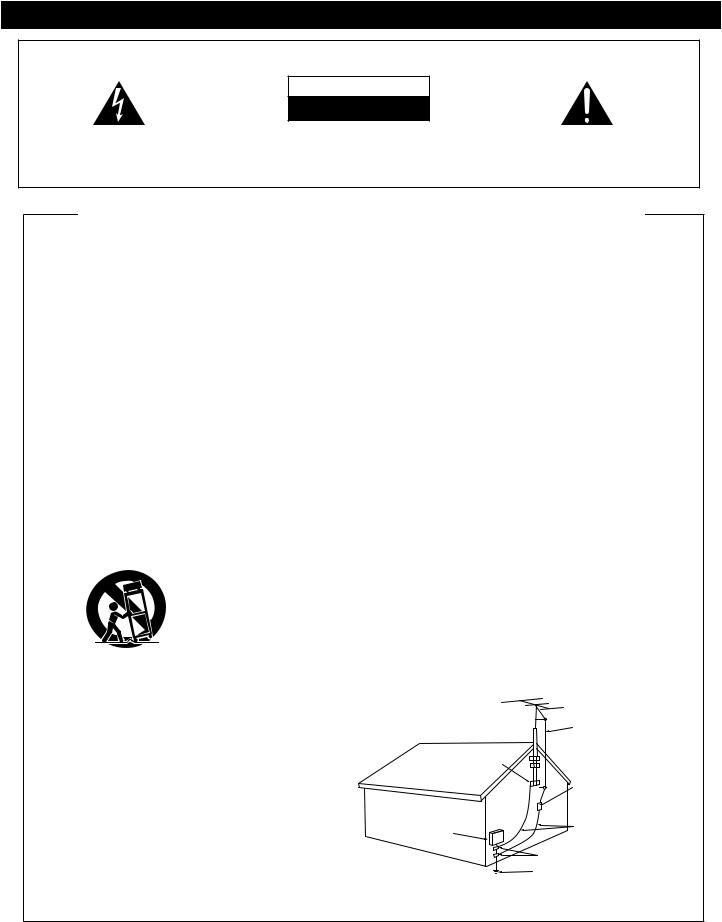
The lightning flash with arrowhead symbol, within an equilateral triangle, is intended to alert the user to the presence of uninsulated "dangerous voltage" within the product'senclosurethatmaybeofsufficientmagnitude to constitute a risk of electric shock to persons.
CAUTION: TO REDUCE THE RISK OF ELECTRIC |
The exclamation point within an equilateral triangle is |
SHOCK, DO NOT REMOVE THE COVER (OR BACK). |
intended to alert the user to the presence of important |
THERE ARE NO USER SERVICEABLE PARTS |
operating and maintenance (servicing) instructions in |
INSIDE REFER SERVICE TO YOUR AUTHORIZED |
the literature accompanying the appliance. |
AMERICAN AUDIO® SERVICE TECHNICIAN. |
|
IMPORTANT SAFETY INSTRUCTIONS
READ INSTRUCTIONS —All the safety and operating instructions should be read before the product is
operated.
RETAIN INSTRUCTIONS — The safety and operating
instructionsshouldberetainedforfuturereference. HEED WARNINGS — All warnings on the product and
in the operating instructions should be adhered to.
FOLLOW INSTRUCTIONS — All operating and use
instructions should be followed.
CLEANING— The product should be cleaned only with apolishingclothorasoftdrycloth.Nevercleanwith furniture wax,benzine,insecticidesorothervolatile
liquids since they may corrode the cabinet. ATTACHMENTS — Do not use attachments not
recommendedbytheproductmanufacturerasthey
may cause hazards.
WATER AND MOISTURE — Do not use this product near water — for example, near a bathtub, wash bowl,kitchensink,orlaundrytub;inawetbasement;
or near a swimming pool; and the like. ACCESSORIES —Do not place this product on an
unstable cart, stand, tripod, bracket, or table. The product may fall, causing serious injury to a child or adult, and serious damage to the product. Use only with a cart, stand, tripod, bracket, or table recommended by the manufacturer, or sold with the product. Any mounting of the product should follow the manufacturer’s instructions, and should use a mounting accessory recommended by the manufacturer.
CART — A product and cart combination should be movedwithcare.Quickstops,excessiveforce,and uneven surfaces may cause the product and cart combination to overturn.
VENTILATION— Slots and openings in the cabinet are provided for ventilation and to ensure reliable operation of the product and to protect it from overheating, and these openings must not be blocked or covered. The openings should never be blocked by placing the product on a bed, sofa, rug, or other similar surface. This product should not be placed in a built-in installationsuch as a bookcase or rack unless proper ventilation is provided or the
manufacturer’s instructions have been adhered to. POWERSOURCES—This product should be operated
onlyfromthetypeofpowersourceindicatedonthe marking label. If you are not sure of the type of power supply to your home, consult your product
dealer or local power company.
LOCATION – The appliance should be installed in a
stable location.
NONUSE PERIODS– The power cord of the appliance should be unplugged from the outlet when left unused for a long period of time.
GROUNDING OR POLARIZATION |
OBJECTANDLIQUIDENTRY- Never push objects of |
• Ifthisproductisequippedwithapolarizedalternating |
any kind into this product through openings as they |
currentlineplug(aplughavingonebladewiderthan |
may touch dangerous voltage points or short-out |
theother),itwillfitintotheoutletonlyoneway.This |
parts that could result in a fire or electric shock. |
isasafetyfeature.Ifyouareunabletoinserttheplug |
Never spill liquid of any kind on the product. |
fullyintotheoutlet,tryreversingtheplug.Iftheplug |
SERVICING — Do not attempt to service this product |
should still fail to fit, contact your electrician to |
yourselfasopeningorremovingcoversmayexpose |
replace your obsolete outlet. Do not defeat the |
you to dangerous voltage or other hazards. Refer all |
safety purpose of the polarized plug. |
servicing to qualified service personnel. |
• If this product is equipped with a three-wire |
DAMAGEREQUIRINGSERVICE - Unplugthisproduct |
groundingtypeplug,aplughavingathird(grounding) |
from the wall outlet and refer servicing to qualified |
pin,itwillonlyfitintoagroundingtypepoweroutlet. |
service personnel under the following conditions: |
Thisisasafetyfeature.Ifyouareunabletoinsertthe |
• When the power-supply cord or plug is damaged. |
plug into the outlet, contact your electrician to |
• If liquid has been spilled, or objects have fallen into |
replace your obsolete outlet. Do not defeat the |
the product. |
safety purpose of the grounding type plug. |
• If the product has been exposed to rain or water. |
POWER-CORD PROTECTION - Power-supply cords |
• Iftheproductdoesnotoperatenormallybyfollowing |
should be routed so that they are not likely to be |
theoperatinginstructions.Adjustonlythosecontrols |
walked on or pinched by items placed upon or |
that are covered by the operating instructions as an |
against them, paying particular attention to cords at |
improper adjustment of other controls may result in |
plugs,conveniencereceptacles,andthepointwhere |
damage and will often require extensive work by a |
they exit from the product. |
qualified technician to restore the product to its |
OUTDOOR ANTENNA GROUNDING — If an outside |
normal operation. |
antennaorcablesystemisconnectedtotheproduct, |
• If the product has been dropped or damaged in any |
be sure the antenna or cable system is grounded so |
way. |
astoprovidesomeprotectionagainstvoltagesurges |
• When the product exhibits a distinct change in |
andbuilt-upstaticcharges.Article810oftheNational |
performance — this indicates a need for service. |
ElectricalCode,ANSI/NFPA70,providesinformation |
REPLACEMENT PARTS -- When replacement parts |
with regard to proper grounding of the mast and |
arerequired,besuretheservicetechnicianhasused |
supporting structure, grounding of the lead-in wire |
replacement parts specified by the manufacturer or |
to an antenna discharge unit, size of grounding |
have the same characteristics as the original part. |
conductors, location of antenna-discharge unit, |
Unauthorizedsubstitutionsmayresultinfire,electric |
connection to grounding electrodes, and |
shock, or other hazards. |
requirementsforthegroundingelectrode.SeeFigure |
SAFETY CHECK - Upon completion of any service or |
A. |
repairs to this product, ask the service technician to |
LIGHTNING — For added protection for this product |
performsafetycheckstodeterminethattheproduct |
duringalightningstorm,orwhenitisleftunattended |
is in proper operating condition. |
and unused for long periods of time, unplug it from |
WALLORCEILINGMOUNTING— The product should |
the wall outlet and disconnect the antenna or cable |
not be mounted to a wall or ceiling. |
system. This will prevent damage to the product |
HEAT—Theproductshouldbesituatedawayfromheat |
due to lightning and power-line surges. |
sources such as radiators, heat registers, stoves, or |
POWER LINES —An outside antenna system should |
other products (including amplifiers) that produce |
notbelocatedinthevicinityofoverheadpowerlines |
heat. |
or other electric light or power circuits, or where it |
|
can fall into such power lines or circuits. When |
|
installing an outside antenna system, extreme care |
|
should be taken to keep from touching such power |
|
lines or circuits as contact with them might be fatal. |
|
OVERLOADING — Do not overload wall outlets, |
|
extensioncords,orintegralconveniencereceptacles |
|
as this can result in a risk of fire or electric shock. |
ANTENNA |
|
|
|
LEAD IN |
|
WIRE |
|
GROUND |
|
CLAMP |
|
ANTENNA |
|
DISCHARGE UNIT |
|
(NEC SECTION 810-20) |
ELECTRIC |
GROUNDING CONDUCTORS |
SERVICE |
(NEC SECTION 810-21) |
EQUIPMENT |
|
|
GROUND CLAMPS |
|
POWER SERVICE GROUNDING |
Fig. A |
ELECTRODE SYSTEM |
|
(NEC ART 250, PART H) |
NEC — NATIONAL ELECTRICAL CODE
©American Audio® - www.AmericanAudio.us - Velocity™ Instruction Manual Page 4

SAFETY INSTRUCTIONS
I.Read Instructions - All the safety and operating instructions should be read before the CD Player is operated. The safety and operating instructions should be saved for future reference.
2.Heed Warnings - All warnings on the CD Player and in the operating instructions should be adhered to.
3.Water and Moisture - The player should not be used near water - for example, near a bath tub, kitchen sink, laundry tub, in a wet basement or near a swimming pool, etc.
4.Ventilation-TheCDPlayershouldbesituated so that its location or position does not interfere with its proper ventilation. For example, the CD player should not be situated on a bed, sofa, rug, or similar surface that may block the ventilation openings; or, placed in a built-in installation, such as a bookcase or cabinet that may impede the flow of air through the ventilation openings.
5.Heat - The CD player should be situated away from heat sources such as radiators, heat registers, stoves, or other appliances (including amplifiers) that produce heat.
6.Power Sources - The CD player should be connected to a power supply only of the type described in the operating instructions or as marked on the CD Player.
7.Servicing - The user should not attempt to service the CD Player beyond that described in the operating instructions. All other servicing should be referred to qualified service personnel. The Player should be servicedbyqualifiedservicepersonnelwhen:
A.The power-supply cord or the plug has been damaged.
B.Objects have fallen, or liquid has been spilled into the CD Player.
C.The CD Player has been exposed to rain or water.
D.The CD Player does not appear to operate normally or exhibits a marked change in performance.
Line Voltage Selection
Because power supplies vary from location to location we have incorporated a selectable power supply.
•The desired voltage may be set with the VOLTAGE SELECTOR switch on the rear panel (using a flat head screw driver).
•Do not force the VOLTAGE SELECTOR switch as this may cause damage
•If the VOLTAGE SELECTOR switch does not move smoothly, please contact a qualified service technician.
|
A M E R IC A N A U D IO |
|
|
|
|
|
|
|
|
|
M O D E L N O . : V E L O C I T Y |
|
|
|
|
|
|
|
|
|
D U A L C O M P A C T D I S C P L A Y E R |
|
|
|
|
|
|
|
|
|
P O W E R S O U R C E : |
|
|
|
|
|
|
|
|
|
1 1 5 /2 3 0 V ~ |
5 0 /6 0 H z : 2 5 W |
|
|
|
|
|
|
|
|
|
M A D E I N T A I W A N |
|
|
|
|
|
|
|
|
|
|
|
A C IN ~ |
|
|
|
|
|
C O N N E C T T O |
D IG IT A L O U T |
|
A U D IO O U T |
C O N N E C T T O |
D IG IT A L O U T |
|
A U D IO O U T |
||
C O N T R O L U N IT 2 |
|
F L A S H |
C U E |
|
C O N T R O L U N IT 1 |
|
F L A S H |
C U E |
|
|
|
|
|
1 1 5 V |
2 3 0 V |
|
|
|
|
|
|
|
R |
L |
|
|
|
R |
L |
VOLTAGE SELECTOR SWITCH
The serial and model number for this unit is located on the rear panel. Please write down the numbers here and retain for future reference.
Model No.________________________________
Serial No.________________________________
Purchase Notes:
Date of Purchase__________________________
Dealer Name______________________________
Dealer Address____________________________
_________________________________________
________________________________________
Dealer Phone_____________________________
©American Audio® - www.AmericanAudio.us - Velocity™ Instruction Manual Page 5

UNPACKING
Every Velocity™ has been thoroughly tested and has been shipped in perfect operating condition. Carefully check the shipping carton for damage that may have occurred during shipping. If the carton appears to be damaged, carefully inspect your CD player for any damage and be sure all equipment necessary to operate the CD player has arrived intact. In the event damage has been found or parts are missing, please contact our toll free customer support number for further instructions. Please do not return the CD player to your dealer without first contacting customer support.
INTRODUCTION
Introduction:
Congratulations and thank you for purchasing the American Audio® Velocity™ CD player. This CD player is a representation of American Audio’s continuing commitment to produce the best and highest quality audio products possible at an affordable price. Please read and understand this manual completely before attempting to operate your new CD player. This booklet contains important information concerning the proper and safe operation of your new CD player.
Customer Support:
American Audio® provides a toll free customer support line, to provide set up help and answer any question should you encounter problems during your initial set up or operation. You may also visit us on the web at www.AmericanAudio.us for any comments or suggestions. Service Hours are Monday through Friday 9:00 a.m. to 5:30 p.m. Pacific Standard Time.
Voice: |
(800) 322-6337 |
Fax: |
(323) 582-2610 |
E-mail: |
support@AmericanAudio.us |
To purchase parts online visit http://parts.americandj.com
Caution! There are no user serviceable parts inside this CD player. Do not attempt any repairs yourself, without being instructed to do so by an authorized American Audio service technician. Doing so will void your manufactures warranty. In the unlikely event your CD player may require service, please contact American Audio® customer support.
Do not discard the packing carton in the trash. Please recycle when ever possible.
SET-UP PRECAUTIONS
Please be sure to make any connections before plugging the CD player in to an electrical outlet. All fader and volume controls should be set to zero or minimum position, before the CD player is switched on. If the CD player has been exposed to drastic temperature fluctuation (e.g. after transportation), do not switch on the CD player immediately. The arising condensation of water might damage your device. Leave the device switched off until it has reached room temperature.
Operating Determinations:
•When installing this CD player, please make sure that the device is not exposed or will not be exposed to extreme heat, moisture or dust!
•Do not operate the CD player in extremely hot (more than 30°/100°F) or extremely cold (less than 5°C/40°F) surroundings.
•Keep the unit out of direct sunlight and away from heaters.
•Operate the CD player only after becoming familiar with its' functions. Do not permit operation by persons not qualified for operating the unit. Most damages are the result of unprofessional operation.
©American Audio® - www.AmericanAudio.us - Velocity™ Instruction Manual Page 6

MAIN FEATURES
• 8 times over sampling 1 bit D/A converter |
• Music Master tempo |
|
• |
Auto cue |
• Real Time Scratch Play |
• 1/75th second frame search |
• Reverse Play |
|
• Real time cue (“Cue on the Fly”) |
• Pan Effect |
|
• 8 different speed scan (4 Forward/4 Reverse) |
• Skid Effect |
|
• |
Pitch display |
• Filter Effect |
• Digital RCA coaxial output |
• Phase Effect |
|
• Large bright Digital Screen can be viewed from wide angles. |
• Echo Effect |
|
• Fader “Q” Start Control (a) |
• Flanger Effect |
|
• Seamless Loop (uninterrupted loop playback) |
• Robot Effect |
|
• Sampler (Forward & Reverse Sampling) |
• Trans Effect |
|
• |
Bop Effect (b) |
• Digital Anti-Shock |
• Flip-Flop (Relay Playback) (c) |
• Beat Synchronized Effects |
|
• Jog Wheel Pitch Bend +/-100% |
• Slot Indicator Light |
|
• Memory Backup, Defaults to last setting (d) |
• System Lock Function |
|
• 3 Programmable Cue (Flash Start ) Buttons |
• Selectable Single or Continuous Play |
|
• Slot Loading Drive - No more Transport Tray |
• Unique FX Mix Function |
|
• 384 programmable Cue Points (128 x 3) (e) |
• Flash Function (f) |
|
•Adjustable Pitch Percentages: +/-4%, +/-8%, +/-16% or +/-100%
•Instant Start within 10 ms (sound is produced immediately when the PLAY button is pressed)
(a)FADER “Q” START CONTROL: This feature is used in conjunction with most American Audio® and American DJ® audio mixers that also feature “Fader Q-Start” control. Connect your Velocity as described in the set-up section of this manual. After set up is completed load CDs into both players. By moving the mixer’s crossfader from left to right you can start and pause the Velocity™ playback functions. For Example, if the mixer’s crossfader is all the way to the left (player one is playing and player two is in cue or pause mode), and you move the fader at least 20% to the right, player two (2) will begin to play and player one (1) will return to cue mode. When the crossfader is to the right, and you move it 20% to the left, player one (1) will begin to play and player two (2) will return to its’ cue point. You can create great effects similar to scratching with this feature. After storing cue points on each side of the CD player, different songs or samples may quickly be recalled by moving the mixer crossfader back and forth. New cue points can be easily selected on the Velocity™ player (see setting cue points page 18). “Q” Start control is easy to use and mastering this feature will help you create amazing effects with your music. Note: For proper “Q” Start operation on mixers with a "Hamster" switch, be sure the “Hamster” setting is set to 1/2 (Normal Setting).
(b)BOP EFFECT: The Bop Effect button serves two features. First, it is a stutter effect, creating a sound similar to a sampler. Second, it will return to the last Cue point in memory instantly. This will allow you to create great effects. To create the BOP Effect, see BOP Effect on page 24.
(c)FLIP-FLOP: This feature is used in conjunction with American Audio® mixers that also feature Fader “Q” Start. For
FLIP-FLOP results you must use two (2) Velocity™ players. Connect your Velocity’s as described in the set-up section of this manual. This feature will start the next player once one (1) player has ended. For example, if player one (1) is playing a disc and it ends, player two (2) will instantly begin to play. You may set FLIP-FLOP to play track to track or disc to disc. For more information on this feature, see FLIP-FLOP™ on page 37.
(d) MEMORY BACKUP: The Velocity™ has a five (5) year memory back-up, that will save your setting in case the power supply is accidentally disconnected. Velocity™ will remember your last setting (SGL, CTN, and effect parameters) even if you disconnect your main power. The Velocity™ will store your cue points and samples in memory if you accidentally eject a disc or shut off the power. See memory on page 26.
(e)PROGRAMMABLE CUE POINTS: The Velocity™ has three Flash Start Buttons (8). 128 Cue points can be stored in each of the FLASH START BUTTONS (6), for a total of 384. These cue points can be stored into the unit's internal memory and may be recalled at any time. See setting "Cue Points" on page 18.
(f)FLASH START FUNCTION: This feature is used in conjunction with most American Audio® and American DJ® audio mixers that also feature “Fader Q Start” control. This function work similar to the Fader "Q" Start Control described above. In this case the crossfader is used to start and stop any sample that is stored in the players memory.
©American Audio® - www.AmericanAudio.us - Velocity™ Instruction Manual Page 7

SET-UP
1. Checking the Contents |
|
|
|
|
Be sure your Velocity™ was shipped with the following: |
|
|
|
|
1) |
Velocity™ Transportation Unit |
2) |
Velocity™ Controller Unit |
|
3) |
Operating Instructions (This Booklet) |
4) |
Two (2) |
Control Cables |
5) |
Two (2) "Q-Start" 1/8” mini plug. |
6) |
Two (2) |
Sets of Stereo RCA Cables |
7)Warranty card.
2.Installing the Units
1)Place your unit on a flat surface or mount it in a secure rack mount case.
2)Be sure the player is mounted in a well ventilated area where it will not be exposed to direct sunlight, high temperatures, or high humidity.
3)Try to place the unit as far as possible from TVs and tuners, as the unit may cause undesirable interference.
3.Connections
1)Be sure main power is connected last to prevent any electrical damage.
2)AUDIO CONNECTIONS: Use the included RCA cable to connect the Velocity™ outputs to the line inputs of a mixer. Never connect a CD player's output to a mixers "phono" inputs.
3)CONTROL JACK CONNECTIONS: Use the supplied 1/8” mono mini plug cable to connect your Velocity™ to a mini jack connection (A or B) on a compatible American Audio® “Fader Q Start” mixer. (This will enable the Fader “Q” Start function - See “Q” start control page 7).
4)Connect the suppled D-Plug control cables from the transport unit to the controlling unit. Be sure to transport drive one is connected to controlling unit one and transport drive two is connected to controlling drive two.
CAUTION:
•Be sure to use the supplied mono 1/8" control cables. Using other types of cable may result in unit damage
•To avoid sever damage to the unit, be sure the power is off when making connections to the unit.
Installation Note:
The player will work normally when the main unit is mounted with the front panel within 15 degrees of the vertical plane If the unit is tilted excessively, disks may not be loaded or unloaded
properly. (Figure 1)
Installation Note:
The LCD is designed to be clearly visible within the angles shown in Figure 2. Mount the control unit so that the visual angle is within this range.
Figure 1 |
Figure 2 |
©American Audio® - www.AmericanAudio.us - Velocity™ Instruction Manual Page 8

GENERAL FUNCTIONS AND CONTROLS |
|
|
|
|
|
|
|||||||||||||
|
|
|
|
|
|
|
|
|
|
|
|
|
|
|
|
|
|
|
Figure 3 |
1 |
2 |
3 |
4 |
5 |
6 |
7 |
8 |
9 |
10 |
11 |
12 |
13 |
14 |
15 |
16 |
17 |
18 |
19 |
20 |
22 |
24 |
26 |
|
28 |
30 |
32 |
|
34 |
21 |
23 |
25 |
27 |
29 |
31 |
33 |
36 |
35 |
C O N N E C T T O |
C O N N E C T T O |
C O N T R O L U N IT 2 |
C O N T R O L U N IT 1 |
A. CONTROLLER UNIT (FIGURE 3)
1. RELOOP BUTTON - If a SEAMLESS LOOP has been made (see setting a SEAMLESS LOOP on page 17), but the CD Player is not actively in SEAMLESS LOOP mode (a loop is not playing), pressing the RELOOP BUTTON will instantly reactivate the SEAMLESS LOOP mode. To exit loop, press the OUT BUTTON (2). LOOP and
RELOOP will appear in the LCD DISPLAY (16) when the RELOOP function is available.
2. OUT BUTTON - This button is used to set the ending point of a loop. A loop is started by pressing the IN BUTTON (32), pressing the OUT BUTTON set the loop ending point. The loop will continue to play until the OUT BUTTON is pressed once again.
©American Audio® - www.AmericanAudio.us - Velocity™ Instruction Manual Page 9

GENERAL FUNCTIONS AND CONTROLS (Cont.)
3. 
 TRACK BUTTON - This buttons is used to select a track. Tapping this button will back skip on track, holding down this button will rapidly BACK SKIP through the tracks.
4.
 TRACK BUTTON - This buttons is used to select a track. Tapping this button will forward skip to the next track, holding down this button will rapidly forward skip through the tracks.
5.SGL/CTN - This function allows you to choose between single track play or continuous track play (all tracks in order). This function also operates in PROGRAM and FLIP FLOP modes.
6.FX MIX - This button activates the FX-MIX mode This mode will automatically stop a playing track or sample and restart from a selected cue point.
7.FILTER/PHASE BUTTON - This button is used to activate and deactivate either the Filter or Phase effect. See built-in effects on page 28.
8.ECHO/FLANGER EFFECT - This button is used to activate and deactivate either the ECHO or FLANGER effect. See built-in effects on page
9.FX SELECT BUTTON - The effects are located on two different layers. This button allows you to select an effect on a different layer.
10.TIME MODE - The TIME button will switch the time value described in the TIME METER between ELAPSED PLAYING TIME, TRACK REMAINING TIME, and TOTAL REMAINING TIME.
11.EJECT FUNCTION - Pressing this will eject the CD. The eject function will only when the unit is in cue mode, this is to prevent accidentally ejecting the disc when in play mode.
12.MEMORY BUTTON - This button allows you to program up to 3 cue points or three samples in to the three FLASH BUTTONS (30). The samples or cue point can then be recalled at any time even when the disk has been removed and replaced at a later time.
13.PARAMETER TIME - This knob is used to adjust the parameter time value.
14.PARAMETER RATIO - This knob is used to adjust the parameter ratio value.
15.SEARCH - The search function has four forward and four reverse speed positions allowing you to quickly scan through tracks. The more you turn the wheel in either direction, the faster your search.
16.LCD DISPLAY - This high quality LCD display indicates all the functions, as they are occurring. This display is viewable at several comfortable angles (see page 8). The display ICONS will be explained in the section D.
17.SCRATCH/SKID BUTTON - This button is used to activate and deactivate either the Scratch or Skid effect. See built-in effects on page 31.
18.HOLD BUTTON - This button allows you to set and lock any new parameters you set to the effects. This button will glow bright blue when the hold function is activated. If the hold function is not selected any changes to the effect parameters will be momentary.
19.TRANS/PAN EFFECT - This button is used to activate and deactivate either the TRANS or PAN effect. See built-in effects on page 33.
20.REV/PLAY - This button activates reverse play mode This function will play your track or sample in reverse. All pitch and effect functions will operate normally in this mode
21.CUE - Pressing the CUE button during playback immediately pauses playback and returns the track to the last set cue point (see setting a CUE POINT, page 18). The red CUE LED will glow when the unit is in cue mode The LED will also flash every time a new CUE POINT is set. The CUE button can be held down to momentarily play the CD. When you release the CUE button it instantly returns to the CUE POINT. You can also tap the CUE button to create a BOP EFFECT (for definition of BOP EFFECT, see page 24).
22.PLAY/PAUSE BUTTON - Each press of the PLAY/PAUSE BUTTON causes the operation to change from play to pause or from pause to play. While in play mode the green play LED will glow, and while in pause mode the green play LED will
©American Audio® - www.AmericanAudio.us - Velocity™ Instruction Manual Page 10
GENERAL FUNCTIONS AND CONTROLS (Cont.)
flash.
23.JOG WHEEL/EFFECTS PLATTER - This wheel has three functions;
A. The jog wheel will act as a frame search control when the CD is in pause or cue mode, allowing you to set a cue point.
B. The wheel also works as a pitch bend during Playback. Turning the wheel clockwise will increase the pitch percentage up to 100%, andturningthewheelinthecounter-clockwise direction will decrease the pitch percentage down to -100%. The pitch bend will be determined on how long you turn the jog wheel continuously.
C. The jog wheel will also control the bop function and a speed effect when the jog wheel effect function is activated, see page 32.
24.TEMPO LOCK FUNCTION - This button activates the TEMPO LOCK function. This function allows you to use the PITCH SLIDER to speed up or slow down playback speed without altering the tonal pitch of the track. When this function is not engaged the original tonal pitch of the track will be altered giving you the "chipmunk" effect when a track is played at a high rate of speed, or the "James Earl Jones" effect when a track is slowed to much. To turn this function off, press and hold down this button for at least 1 second and then release.
25.(-) PITCH BEND BUTTON - The (-) pitch bend function creates a momentary “Slow Down” in the CD’s BPM’s (Beats per minute) while it is playing. This will allow you to match the beats between two playing CD’s or other playing music source. Remember, this is a momentary function. When you remove your finger from the pitch button, the BPM’s will automatically return to PITCH SLIDERS (35) pitch value Holding down this button will give a maximum of -100% pitch. Use this function to slow to another playing music source. Be sure to notice that this function is a momentary pitch adjustment, for a more precise adjustment use the PITCH SLIDER (35) to match the BPM’s with another playing music source.
26.(+) PITCH BEND BUTTON - The (+) pitch
bend function creates a momentary “BUMP” in the CD’s BPM’s (Beats per minute) while it is playing. This will allow you to match the beats between two playing CD’s or any other music source. Remember, this is a momentary function. When you remove your finger from this button, the BPM’s will automatically return to PITCH SLIDERS (35) selected pitch. Holding down this button will give a maximum of +100% pitch.
27.BPM BUTTON - The BPM button is used to toggle between two readouts in the LCD (16). When the BPM function is activated, the LCD (16) will display a BPM meter. The BPM meter will automatically and accurately detail a tracks beats per a minute (BPM). When this function is not active the LCD will display the amount of pitch (if any) that is being applied to the track.
28.TAP BUTTON - This button is used to override and manually set a tracks BPM. Occasionally the built-in BPM meter may not function as desired. This button allows you to override the internal beat clock and manually set a tracks BPMs. To manual set the BPMs; tap this button a few times to a tracks heavy down beat, the unit will automatically calculate your tapping and translate it into a tracks BPMs. The BPM READOUT is then displayed in the LCD (16). To return to the automatica BPM counter, press and hold down the BPM BUTTON (27) for at least 1 second and then release.
29.P.S.P. (Pre Set Parameters) BUTTON - This button is used to activate the effect preset. Each effect comes with six presets, this button access the presets. See page 31 for more information on the presets.
30.FLASH BUTTONS 1-3 - These button are used to store either three (3) cue points or three
(3) samples. Each Flash Button can store either a sample or a cue point.
31.SAMPLER BUTTON - This is used to activate the sampler function. When this function is activated a created sample will play in a continuos loop mode.
32.LOOP IN BUTTON - “CUE ON THE FLY” - This function allows you to set a CUE POINT (see
©American Audio® - www.AmericanAudio.us - Velocity™ Instruction Manual Page 11

GENERAL FUNCTIONS AND CONTROLS (Cont.)
CUE POINT page 18) without music interruption (“on the fly”). This button also sets the starting point of a seamless loop (see SEAMLESS LOOP).
33.BOP/ENTER BUTTON - During play mode, pressing the BOP button will instantly return play to the last set cue point without interruption of music. Use this function to create a stutter effect. When using the FX MIX (see page 34), this button will activate the FX MIX function.
34.PITCH ON/OFF BUTTON - This button is used to turn the PITCH SLIDER (35) function on and off. This button will also change the pitch percentage the PITCH SLIDER (35) will react to. The pitch percentage can be changed between 4%, 8%, 16% and 100%. 4% will allow the least amount of pitch manipulation and 100% will allow the most amount of pitch manipulation. To adjust to the different values please see page 25. The LED above the PITCH ON/OFF BUTTON will indicate which pitch percentage mode you are in, glowing red for 4%, glowing green for 8%, glow-
ing orange for 16% or flashing green for 100%. Note when LED is not glowing in any color the Pitch Function is not activated.
35.PITCH SLIDER - This slider is used to adjust the playback pitch percentage. The slider is a set adjustment and will remain set until the pitch slider is moved or the pitch function has been turned off. This adjustment can be made with or without a disk in the drive. The pitch adjustment will remain even if a disc has been remove and will reflect on any other disc loaded into the player. That is to say, if you set a +2% pitch on one disc, remove that disc and insert another, that disc too will have a +2% pitch. The amount of pitch being applied will be displayed in the LCD (16).
36.CONTROL UNIT CONNECTOR - This connector is used to send the control information to the transport unit. Connect the supplied D-Plug cables from these jacks to the similar marked jacks on the transport unit.
©American Audio® - www.AmericanAudio.us - Velocity™ Instruction Manual Page 12
 Loading...