


Professional Power Amplifi er
AMERICAN AUDIO®
4295 Charter Street
Los Angeles Ca. 90058
Revised 02/02
MONO STEREO BRIDGE
POWER |
LIMITER |
|
LIMITER |
|
|
ON |
OVER HEAT |
ON |
|
ON |
|
PROTECT |
|
|
|
|
CLIP |
|
|
|
|
-5dB |
|
|
|
|
-10dB |
|
|
OFF |
|
-15dB |
|
|
0 |
10 |
SIGNAL |
0 |
10 |
|
PROFESSIONAL POWER AMPLIFIER
V4000plus
User Instructions
©American Audio® - www.americandj.com - V4000plus™ Power Amplifier User Manual Page 2

CAUTION
Do not open - risk of electric shock
CAUTION: TO REDUCE THE RISK OF ELECTRIC SHOCK, DO NOT REMOVE THE COVER.
THERE ARE NO USER SERVICEABLE PARTS INSIDE. REFER ALL SERVICE TO YOUR AUTHORIZED AMERICAN AUDIO® DEALER.
The lightning flash with an arrow triangular symbol is intended to alert the user to the presence of non insulated “dangerous voltage” within the products enclosure, and may be of sufficient magnitude to constitute a risk of electric shock.
The exclamation point triangular symbol is intended to alert the user to the presence of important operating and maintenance
(servicing) instructions in the user manual accompanying the amplifier.
FOR OPTIMUM PERFORMANCE AND RELIABILITY DO NOT PRESENT THE AMPLIFIER WITH A SPEAKER LOAD OF LESS THAN 2 OHMS OR ANY COMBINATION OF SPEAKERS THAT TOGETHER ARE LESS THAN 2 OHMS!
USING ONE SPEAKER, IT MUST BE RATED AT 4 OR MORE OHMS.
USING TWO SPEAKERS, THEY MUST RATED EACH AT 4 OR MORE OHMS.
USING THREE SPEAKERS, THEY MUST BE RATED EACH AT 8 OR MORE OHMS.
POUR ASSURER LA FIABILETE ET OBTENIT UNE PERFORMANCE OPTIMALE, NESOUMETTE JAMAIS L’AMPLIFICATEUR A UNE CHARGE D’IMPEDANCE TOTALE INFERIEURE A 2 OHMS, NI AVEC UN H.P. NI EN COMBINAISON DES H.P.
AVEC UN H.P., IL FAUT UNE CHARGE D’IMPEDANCE MINIMUM DE 2 OHMS.
AVEC DEUX H.P., FAUT POUR CHAOUN UNE CHARGE D’IMPEDANCE MINIMUM DE 4 OHMS.
AVEC TROIS H.P., FAUT POUR CHAOUN UNE CHURGE D’IMPEDANCE MINIMUM DE 8 OHMS.
CONTENTS: |
|
SafetyPrecautions........................................................................................................................................................................................ |
4 |
Introduction............................................................................................................................................................................................... |
4 |
FrontPanel.................................................................................................................................................................................................... |
5 |
Rear Panels.................................................................................................................................................................................................. |
6 |
Inputs........................................................................................................................................................................................................... |
7 |
Outputs............................................................................................................................................................................................................ |
7 |
Operating Modes......................................................................................................................................................................................... |
9 |
Protection Circuitry |
|
Limiter................................................................................................................................................................................................. |
10 |
ShortCircuitProtection..................................................................................................................................................................... |
10 |
ThermalProtection........................................................................................................................................................................... |
1 |
Important Features..................................................................................................................................................................................... |
1 |
Speakon Output Connector Assembly....................................................................................................................................................... |
12 |
Specifi cations............................................................................................................................................................................................... |
15 |
©American Audio® - www.americandj.com - V4000plus™ Power Amplifier User Manual Page 3

Important Precautions
 To reduce the risk of electrical shock or fi re, do not expose this unit rain or moisture
 Do not spill water or other liquids into or on to your unit
 Do not attempt to operate this unit if the power cord has been frayed or broken
 Do not attempt to remove or break off the ground prong from the electrical cord. This prong is used to reduce the risk of electrical shock and fi re in case of an internal short
 Disconnect main power before making any type of connection
 Do not remove the cover under any conditions. There are no user serviceable parts inside
 Never plug this unit in to a dimmer pack
 Always be sure to mount this unit in an area that will allow proper ventilation. Allow about 6” (15cm) between this device and a wall
 Do not attempt to operate this unit, if it becomes damaged
 This unit is intended for indoor use only, use of this product outdoors voids all warranties
 During long periods of non-use, disconnect the unit’s main
ower
 Always mount this unit in a safe and stable manner
 Power cords should be routed so they are not likely to be walked on, pinched by items placed upon or against them.
 Cleaning -The outside of the unit should be wipe down with a soft cloth and mild cleaner when needed.
 Heat -The appliance should be situated away from heat sources such as radiators, heat registers, stoves, or other appliances
(including amplifiers) that produce heat.
 The fixture should be serviced by qualified service personnel when:
A.The power-supply cord or the plug has been damaged.
B.Objects have fallen, or liquid has been spilled into the unit.
C.The appliance has been exposed to rain or water.
D.The fixture does not appear to operate normally or exhibits a marked change in performance.
Introduction
Introduction: Congratulations and thank you for purchasing the American Audio® V4000plus™ amplifier. This amplifier is a representation of American Audio’s continuing commitment to produce the best and highest quality products all at an affordable price. Please read and understand this manual completely before attempting to operate your new amplifier. This booklet contains important information concerning the proper and safe operation of your new amplifier.
Unpacking: Every V4000plus™ amplifi er has been thoroughly tested and has been shipped in perfect operating condition.
Carefully check the shipping carton for damage that may have occurred during shipping. If the carton appears to be damaged, carefully inspect your unit for any damage and be sure all accessories necessary to operate the unit has arrived intact. In the event damage has been found or parts are missing, please contact our toll free customer support number for further instructions. Please do not return the amplifi er to your dealer without contacting customer support fi rst.
Installation: This amplifier is designed to mount into a standard 19” rack. The front panel provides four holes used to screw the unit into a rack. The unit also provides a way to rear mount the unit into a rack for added security. Rear mounting the unit is especially recommended for this amplifier if the unit is to mounted into a mobile rack.
Customer Support: American Audio® provides a toll free customer support line, to provide set up help and to answer any question should you encounter problems during your set up or initial operation. You may also visit us on the web at www.americandj.com for any comments or suggestions. For service related issue please contact American Audio® . Service Hours are Monday through Friday 9:00 a.m. to 5:00 p.m. Pacific Standard Time.
Voice: (800) 322-6337
Fax: (323) 582-2610
E-mail: support@americandj.com
©American Audio® - www.americandj.com - V4000plus™ Power Amplifier User Manual Page 4
Front Panel Control
2 |
3 |
4 |
5 |
6 |
8 |
9 10 1 |
12 |
13 |
MONO STEREO BRIDGE
POWER |
LIMITER |
|
LIMITER |
|
|
ON |
OVER HEAT |
ON |
|
ON |
|
PROTECT |
|
|
|
|
CLIP |
|
|
|
|
-5dB |
|
|
|
|
-10dB |
|
|
OFF |
|
-15dB |
|
|
0 |
10 |
SIGNAL |
0 |
10 |
|
PROFESSIONAL POWER AMPLIFIER
Diagram
714
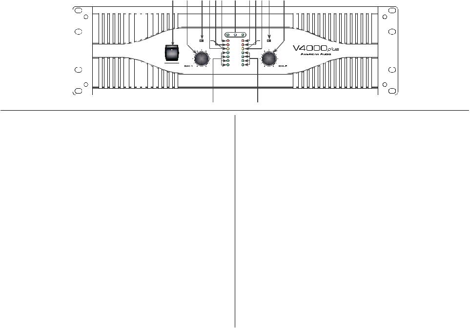
1.Power Switch - This switch is used to control the units main power. 8. Function Indicators - These indicators detail the operating mode of
2.Channel 1 Gain Control - This rotary knob is used to control the output signal of channel one. Turning the knob in a clockwise direction will increase signal output.
3.Channel 1 Limiter Switch - This is used to activate the channels built-in limiter. The limiter reduces the average input level when the signal begins to distort, this process is designed to reduce distortion and protect the speakers. See limiter page 12.
4.Channel 1 Clip Indicator - This red LED will begin to fl ash when channel one begins to overload (clip). At this point channel one will begin to distort. Under heavy clipping activity lower the channel one gain control to reduce the risk of damage to your speakers and amplifi er. This LED may glow when the unit has been turned off, this is normal.
5.Channel 1 Protect Indicator - The red Protect LED will begin to glow when the channel goes into protect mode. When the channel goes into protect mode all output for that channel will turn off. This is to protect any speakers connected to the channel.
6.Channel 1 Overheat Indicator - This indicator will begin to glow when the channel goes into thermal protection mode. When the unit goes into thermal protection, channel output will turn off. See “Thermal
Protection” page 13.
7.Channel 1 Signal Indicators - These green and yellow LED’s will glow according to the average signal output.
the amplifi er. These LEDs will also function as a power indicator.
9. Channel 2 Overheat Indicator - This indicator will begin to glow when the channel goes into thermal protection mode. When the unit goes into thermal protection, channel output will turn off. See “Thermal
Protection” page 13.
10.Channel 2 Protect Indicator - The red Protect LED will begin to glow when the channel goes into protect mode. When the channel goes into protect mode all output for that channel will turn off. This is to protect any speakers connected to the channel.
11.Channel 2 Clip Indicator - This red LED will begin to fl ash when channel one begins to overload (clip). At this point channel one will begin to distort. Under heavy clipping activity lower the channel one gain control to reduce the risk of damage to your speakers and amplifi er. This LED may glow when the unit has been turned off, this is normal.
12.Channel 2 Limiter Switch - This is used to activate the channels built-in limiter. The limiter reduces the average input level when the signal begins to distort, this process is designed to reduce distortion and protect the speakers. See limiter page 12.
13.Channel 2 Gain Control - This rotary knob is used to control the output signal of channel two. Turning the knob in a clockwise direction will increase signal output.
14.Channel 2 Signal Indicators - These green and yellow LED’s will glow according to the average signal output.
©American Audio® - www.americandj.com - V4000plus™ Power Amplifier User Manual Page 5
 Loading...