

Page 1
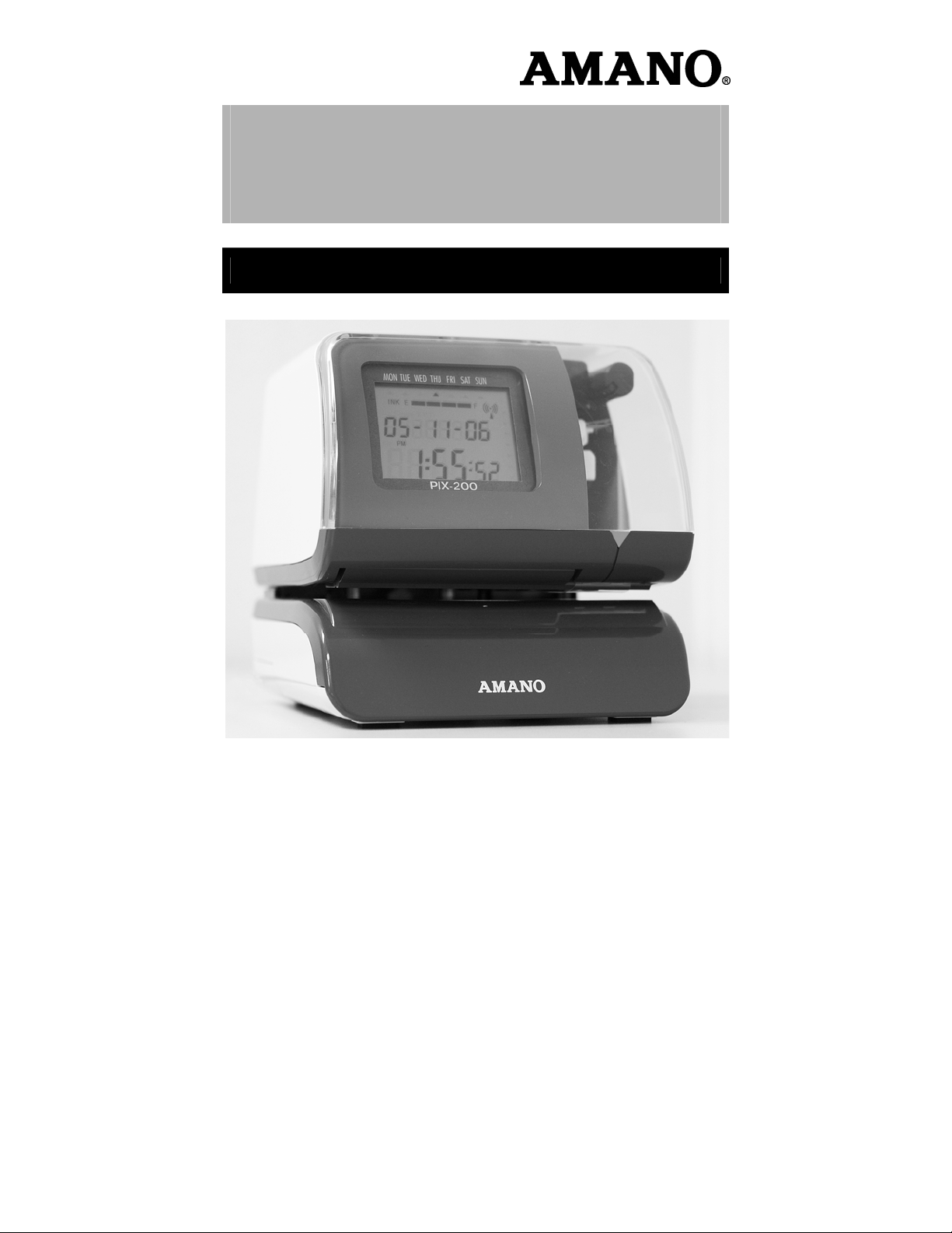
PIX-200
Atomic Time Clock
Operation Manual
Page 2

Proprietary Notice
This document contains proprietary information and such information may not
be reproduced in whole or part without the written permission from Amano
Cincinnati, Inc. 140 Harrison Ave., Roseland, New Jersey 07068.
Amano Cincinnati, Inc. reserves the right to make equipment changes and
improvements, which may not be reflected in this document. Portions of this
document may have been updated to include the latest hardware or firmware
version, if applicable.
To ensure safe use of this time recorder/stamp, be sure to thoroughly read this
manual in its entirety before any attempt is made to operate the equipment.
After you have finished reading this manual, be sure to store it in a safe place
for future reference.
Thank You….
For purchasing another fine product from Amano Cincinnati, Inc.
For Safe and proper operation, please carefully read the
manual before using the time clock and save it for reference.
Warranty Notice
Any claim for warranty, express or implied, due to the clocks failure to properly
receive the radio signal because of interference, whatever may be the source
of this interference, are hereby expressly excluded.
The PIX-200 has the atomic clock (radio-controlled clock) feature which
displays the current time precisely by automatically receiving time code
signals on long wave radio from the transmitting station. The unit receives the
time code signal via its built-in antenna system.
Note: This equipment has been tested and found to comply with the limits for
a Class A digital device, pursuant to part 15 of the FCC Rules. These limits
are designed to provide reasonable protection against harmful interference
when the equipment is operated in a commercial environment. This
equipment generates uses and can radiate radio frequency energy and, if not
installed and used in accordance with the instruction manual, may cause
harmful interference to radio communications. Operation of this equipment in a
residential area is likely to cause harmful interference in which case the user
will be required to correct the interference at his own expense.
Page 3

Table of Contents
GUIDELINES FOR SAFE OPERATION….. .................... 1-3
Chapter 1: Overview ....................................................... 1-5
Specifications .................................................................................. 1-5
Names and Functions of Parts ........................................................ 1-6
LCD Display .................................................................................... 1-7
Description of Controls (function buttons) ....................................... 1-7
Print Position Adjustment (Slide Lever) ........................................... 1-8
Chapter 2: Getting Started ............................................. 2-1
Removing the Cover & Packing Material ........................................ 2-1
Mounting ......................................................................................... 2-1
Wall Mounting ................................................................................. 2-2
Desktop Mounting ........................................................................... 2-3
Performing a Test Print ................................................................... 2-3
Chapter 3: Program Mode .............................................. 3-1
Setting the Time (If the Time Displayed is Incorrect) ...................... 3-1
Easy Way to Set the Time ............................................................... 3-2
Setting the Date (If the Date Displayed is Incorrect) ....................... 3-2
Setting the Date Format .................................................................. 3-3
Date Format Table .......................................................................... 3-4
Setting the Layout for Customized Comments ................................ 3-7
Test Printing for Customized Comments ........................................ 3-8
Changing the Print Position ............................................................. 3-9
Setting the Print Pattern .................................................................. 3-9
Setting the Printing Length ............................................................ 3-12
Setting the Printing Activation/Detecting Sensor ........................... 3-13
Setting the Number ....................................................................... 3-14
Setting the Initial Number and Auto Reset .................................... 3-15
Setting the Repeat Times of a Number ......................................... 3-16
Setting for Daylight Saving Time (DST) ........................................ 3-17
Displaying Settings: Programming Password and Time ............... 3-18
Amano PIX-200 Operation Manual 1-1
Page 4

Chapter 4: Atomic Clock Feature .................................. 4-1
Automatic Reception ....................................................................... 4-1
Setting the Atomic Clock (Germany, UK and others) ..................... 4-3
Setting the Time Zone (US only) ..................................................... 4-4
PIX-200 Atomic Clock/Time Code Signal ........................................ 4-5
Chapter 5: Maintenance and Troubleshooting ............. 5-1
Ribbon Cartridge Replacement ....................................................... 5-1
Cleaning .......................................................................................... 5-1
Error Codes ..................................................................................... 5-2
Chapter 6: Appendix ....................................................... 6-1
1-2
Amano PIX-200 Operation Manual
Page 5
GUIDELINES FOR SAFE OPERATION…..
To ensure safe operation, please carefully read the following warnings and cautions
prior to using the PIX 200 Electronic time recorder/stamp.
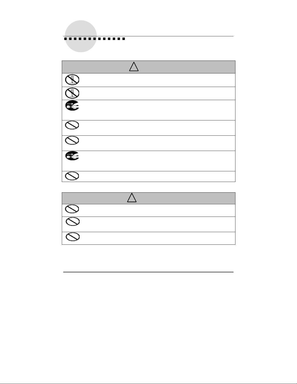
Warning
!
Do not disassemble the unit. There is a high voltage present inside,
possibly leading to an
Do not modify the unit. Modifications may cause a fire and/or electric
shock.
If any anomaly occurs, for example, heat or smoke is generated or an odor
is emitted, unplug the unit immediately and contact your dealer for
servicing. There is a danger that further use may cause a fire or electric
shock.
Do not use any voltage of the power source other than designated.
Do not share a single outlet with another plug. These may lead to fire or
shock hazards.
Do not damage, break, or modify the power cord. Do not put a heavy
object on, pull, or
cord, possibly resulting in a fire or electric shock.
If foreign matter should get in the unit (including a piece of metal, water, or
liquid), disconnect the plug from the outlet immediately and contact your
dealer for servicing. There is a danger that further use may cause a fire or
electric shock.
Do not plug or unplug the unit with a wet hand. You may get an electric
shock.
electric shock.
forcefully bend the cord, either. These may damage the
Caution
!
Do not place the unit on an uneven or tilted surface. This may result in
injuries due to the unit dropping or falling off.
Do not put a water-filled container or a metal object on top of the unit. If
water is spilled or the metallic object slips inside, a fire or shock hazard may
occur.
Do not install the unit in a humid or dusty environment. It may cause a fire
or electric shock.
Amano PIX-200 Operation Manual 1-3
Page 6
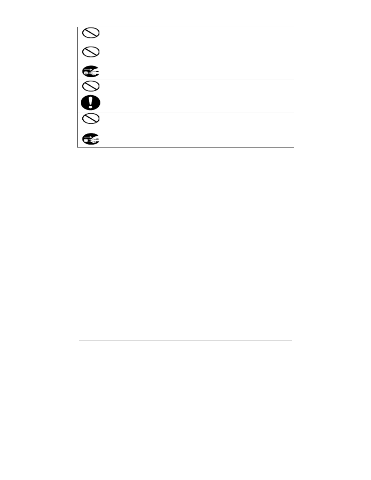
Do not place the unit near kitchen counter or humidifier. Oil, smoke, or
steam generating from them may cause fire or shock hazards.
Do not yank the power cord to disconnect from the outlet. Hold the plug
with your hand to do so, or the cord may be damaged, possibly leading to a
fire or electric shock.
Remove the line cord plug from the outlet before transferring the unit, or it
may damage the cord, possibly leading to a fire or electric shock.
Be careful not to contact the print head, as you may get hurt or burned.
Make sure to insert the power plug as far as it will go. Improper insertion
of the plug may
develop fire or shock hazards.
Do not insert or drop any other time card than specified into the slot. Such
misuse may cause a fire or electric shock.
If the unit should be dropped or the case is broken, unplug the unit and
contact your dealer for servicing. Further use may lead to a fire or shock
hazard.
Relation to the Health and the Environment
The plastic currently used for the outer enclosure of this apparatus does not contain the
halogen substance.
1-4
Amano PIX-200 Operation Manual
Page 7
Chapter 1: Overview
Before attempting to use the Amano PIX-200 time recorder/stamp, please
carefully review Chapter 1: “Overview”, and Chapter 2: “Getting Started”. This
chapter of the manual covers the specifications, accessories, names and
functions of parts, LCD Display, description of controls, and print position
adjustment.
Specifications
Power Requirements:
• Power Supply:
• Power Consumption:
• Battery:
Ambient Temperature:
Ambient Humidity:
Dimensions:
Weight:
Environment:
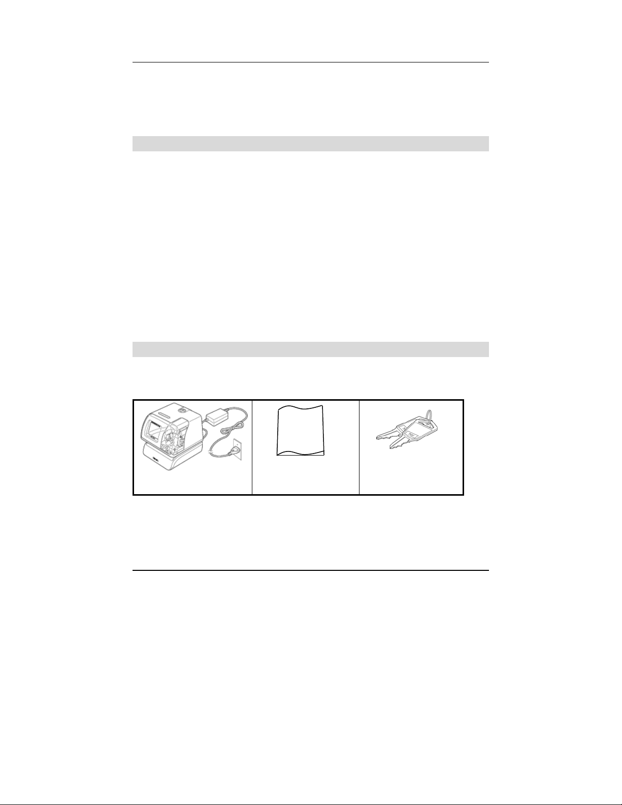
Accessories
The following accessories are provided with the Amano PIX-200. After
unpacking, please ensure that all of the following items are provided:
PIX-200 (1 unit)
• Please note that specifications, appearance, and/or description are
subject to change without notice due to product enhancements.
• This manual has been carefully prepared, but Amano assumes no liability
for errors and/or omissions. If you should find any errors or unclear
information, please contact your Amano dealer.
Amano PIX-200 Operation Manual 1-5
DC 15V
1.2A
Optional Lithium Battery for full power reserve
in case of power failure.
14°F to 113°F (-10°C to 45°C)
32°F to 104°F (0°C to 40°C) if using NiMH
battery option
10% to 90% (non-condensing)
6-1/4"(159 mm) Wide X 6-1/2”(165 mm) High X
6-3/4"(171 mm) Deep.
Approximately 4.85 lbs. (2.2 kg)
Indoor use only; dust-free environment. Keep
out of direct sunlight.
Operation
Manual
This operation
manual (1 copy)
Keys (one pair, 2
keys)
Page 8
utto
p
r
g
(+)
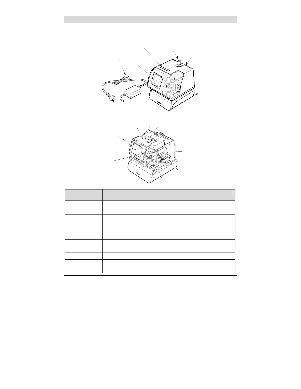
Names and Functions of Parts
The following describes the names and functions of various parts of the PIX-
200.
External View
AC Power
Internal View
LCD Display
Adapte
r
B
LCD
Display
(-) Button
Print
n
Button
(E) Button
Key
Back Plate
Print Window
(+1 Hour Button)
(+1 Min. Button)
Display Label
Ribbon Cartrid
er Senso
Pa
e
Component
Name
AC Adapter Provides clock power.
Keys Used to lock and unlock clock cover.
Back Plate Used to mount the unit to a wall when wall mounting is desired.
LCD Display Used to display information in the front window, i.e., Time & Date.
Print Button Press this button to print in “manual” mode, or when setting the printing
Print Window Large window to assist in accurate printing position.
Buttons 5 control buttons located on top of unit under the cover.
Ribbon Cartridge Easy-to-replace ribbon cartridge.
Clear LED Illuminates the printing position to increase visibility.
Paper Sensor Sensors, which detect the paper position to automatically print.
1-6
Function
activation.
Amano PIX-200 Operation Manual
Page 9
p
y
r
A
y
A
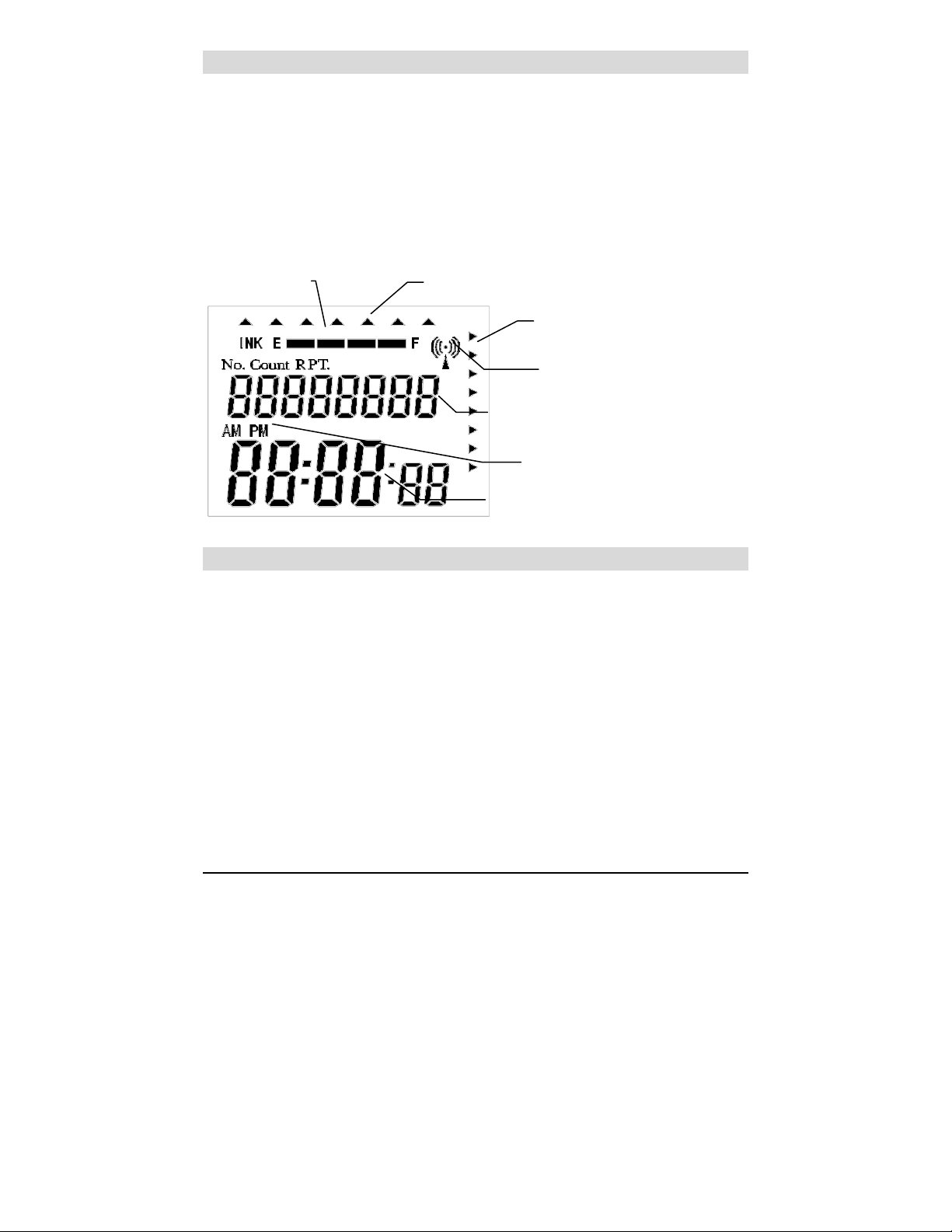
LCD Display
The LCD display contains an ink capacity gauge. This gauge indicates the
amount of ink remaining in the ribbon cartridge using four bar segments, from
E (Empty) to F (Full).
The PIX-200 calculates the remaining ink capacity of the ribbon cartridge from
the number of imprints made. As the ink capacity decreases, the bars in the
gauge will disappear. When the ribbon reaches below 25% capacity, the word
“INK” and “E” will blink until the ribbon is replaced and the ink counter is reset.
(Refer to page 5-1 for Ribbon Cartridge Replacement and Ink counter reset).
The following drawing illustrates the PIX-200 LCD display contents.
Ribbon Cartridge
Ink Ca
acit
Day of the week / Program Indicato
Program Indicator
Date (Year, Month, Date) / Number /
Repeat Times
tomic Time
nchronization Indicator
S
M/PM Indicator
Time (Hour:Minute:Second)
/Programming
Description of Controls (function buttons)
Normally, the Display Window shows the date and time. When you use the
Quick Set or Program Mode to change the settings of the PIX-200, the
instructions to change the clock are shown in this window.
The 5 function buttons underneath the cover are used to navigate through the
Quick Set and Program Mode to change the clock’s settings.
• The (-) button is used to change the information on the display by
decrementing the set value or moving the “▲” to the left.
• The (+) button is used to change the information on the display by
incrementing the set value or moving the “▲” to the right.
• The E button is used to accept the information shown on the display and
save it in memory.
• The +1 HOUR button advances the hour in the display by increments of 1.
• The +1MIN. button advances the minutes in the display by increments of
1.
Amano PIX-200 Operation Manual 1-7
Page 10
j
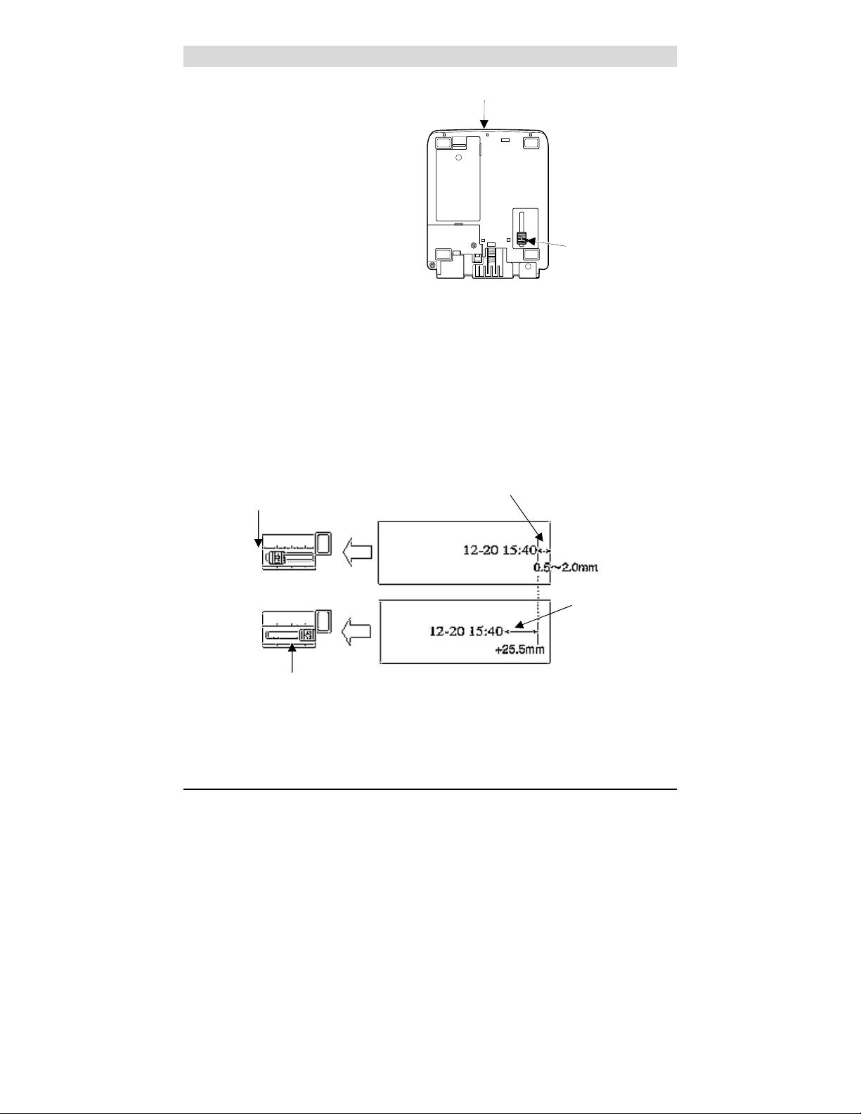
Print Position Adjustment (Slide Lever)
The print position from the paper
edge is adjustable by pressing and
Bottom View
sliding the print position adjuster
(slide lever) located on the right
outside bottom of the PIX-200 unit
as illustrated in the diagram.
The slide lever can be adjusted
using the latching mechanism which
can move a total of 17 increments
with each increment = 1.5mm (for a
total movement = 25.5mm). This
Print Position
Ad
uster
adjuster will move the paperdetecting sensor forward or
backward to change the margin from
the paper edge to the print as illustrated in the following diagram.
The minimum distance from the form edge to print is approximately 0.5mm -
2.0mm. This is achieved when you slide the slide lever to the front of the
machine. The maximum distance from form edge to print is approximately
+25.5mm. This is achieved when you slide the slide lever to the back of the
machine.
Slide Lever Print Position Adjuster
all the way forward
Minimum Distance
Slide Lever Print Position Adjuster
all the way backward
1-8
Maximum
Distance
Amano PIX-200 Operation Manual
Page 11
Chapter 2: Getting Started
Before using the Amano PIX-200 time recorder/stamp, please carefully review
this chapter of the manual, which covers removing cover and packing material,
mounting, and performing a test print.
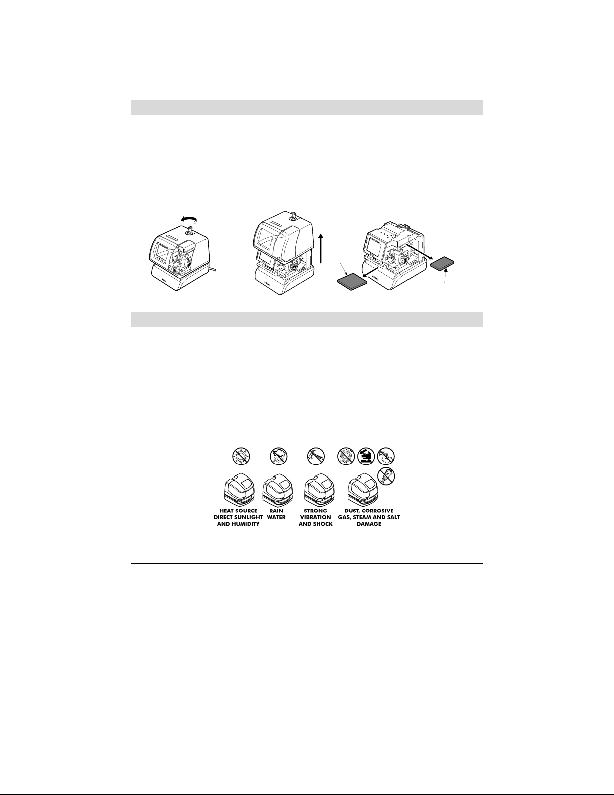
Removing the Cover & Packing Material
You must remove the packaging spacers from the printer block and the Printer
Carriage before attempting to use your PIX-200.
Step 1. Insert the key provided and turn the key counter clockwise to unlock
the cover.
Step 2. Lift the cover to remove.
Step 3. Remove the spacers between the Ribbon Cartridge and the Printer
Carriage.
Step 1 Step 2 Step 3
Mounting
Spacer
Spacer
When choosing a mounting location for your PIX-200, you should consider the
following:
• The mounting surface or hardware must be capable of supporting the unit’s
weight, 2.2 kg (4.85 lbs).
• The area must be within the specified operating temperature range:
14°F~113°F (-10°C~45°C), 10% ~90% relative humidity.
• The unit should be in close proximity to a power source or wall outlet.
• The following conditions should not exist:
• The unit should be mounted in a place able to receive radio signals for
atomic clock signal reception (see page 4-2, for more details).
Amano PIX-200 Operation Manual 2-1
Page 12
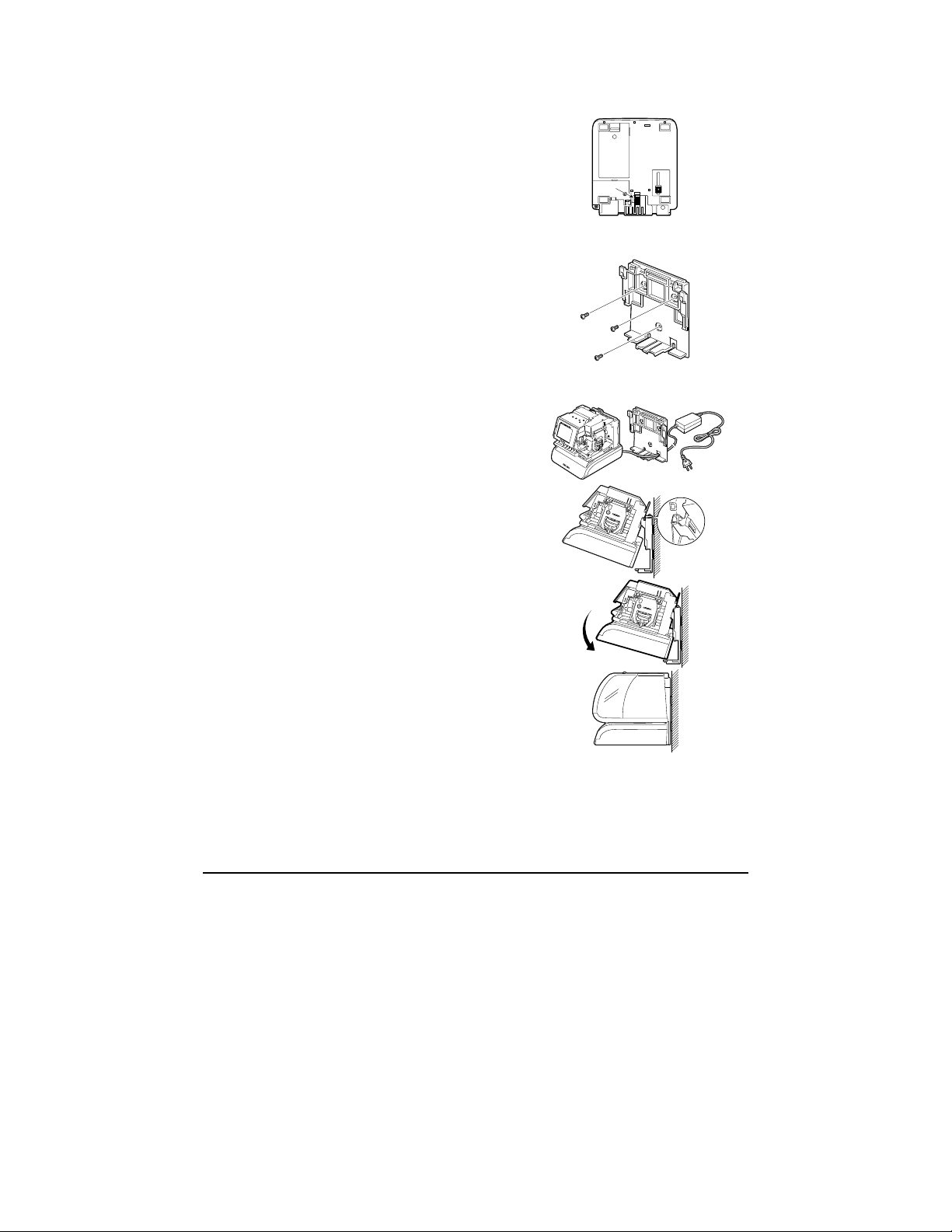
Wall Mounting
To wall mount perform the following:
1. Remove the cover, and remove the
back plate by pressing on the tab
located on the bottom of the unit
towards the rear, and rotating the
bottom of the plate away from the
clock.
2. Using the back plate as a template,
mark the lower mounting hole on the
wall.
3. Mount the plate using a #10 wood
screw (or equivalent).
4. Level the back plate and mark the
location of the two upper mounting
holes. Secure to the wall using #10
wood screws (or equivalent).
5. Feed the cable of the AC power
adapter through one of the holes in the
back plate.
6. Align the clock with the two upper tabs
on the back plate. Tilt the back of the
clock upwards to fully insert the back
plate tabs into the clock. Be careful not
to pinch the power cord with the
bracket.
7. Once the tabs are inserted, tilt the clock
back down and push it against the wall.
The tabs will snap into place.
8. Replace the cover and lock it in place
with keys provided.
Note: Wall mounting should only be performed by authorized Amano dealers.
If the PIX-200 is improperly mounted, it could fall, resulting in damage to
the unit or personal injury. When mounting the PIX-200 on a concrete
wall, or other special wall material, special screws may be required.
Note: The display LED will not light up until the cover has been put back on.
2-2
Amano PIX-200 Operation Manual
Page 13
Desktop Mounting
The PIX-200 should be placed on a level surface with adequate ventilation.
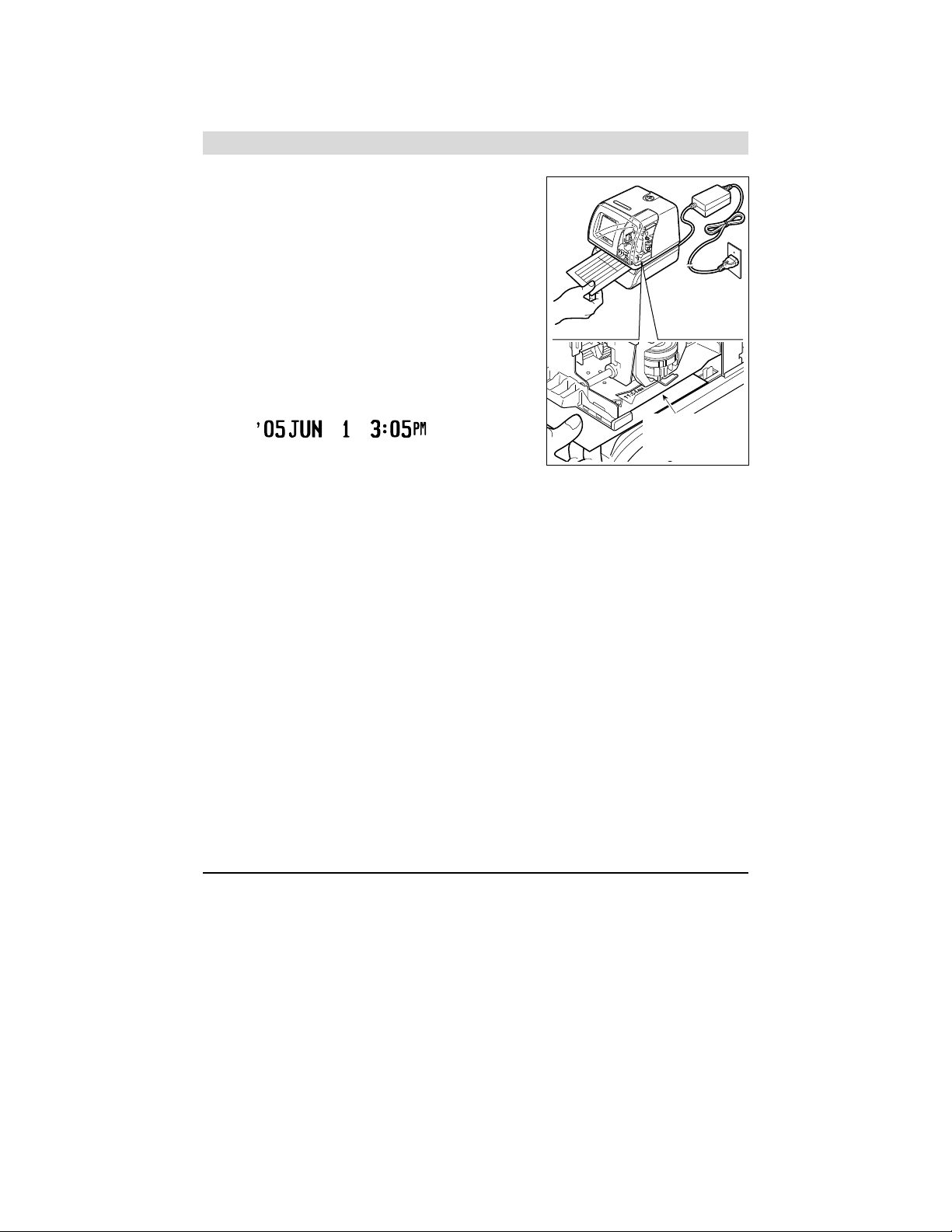
Performing a Test Print
To test print perform the following:
1. Make sure the AC adapter for the
PIX-200 is plugged in.
2. The LED should light up and illuminate
the printing position.
3. Insert a piece of paper or time card along
the guide into the PIX-200. The clock will
automatically print YEAR, MONTH,
DATE and TIME with AM or PM.
IMPRINT SAMPLE:
4. If the imprint format is satisfactory, the
PIX-200 is ready for use.
Print Guide
(metal plate)
Amano PIX-200 Operation Manual 2-3
Page 14

* This page intentionally left blank *
2-4
Amano PIX-200 Operation Manual
Page 15
Chapter 3: Program Mode
Make sure the AC power adapter is plugged in and connected to the PIX-200
before making changes to the clock settings. Unlock and remove the cover.
Locate the (-), (+), E,+1 HOUR, and +1 MIN. buttons on top of the clock.
Note: Replacing the cover during any step of programming will return the
clock to normal date and time display.
Setting the Time (If the Time Displayed is Incorrect)
The illustrations on the right show samples of the displays. The shaded area
means that the symbols, numbers or characters are blinking.
To set the correct time perform the following:
1. Unlock and remove the cover.
2. Press the (+) and (E) buttons on the top of
the unit at the same time, holding down for 2
seconds until Set UP Pro9 appears on the
display. The “▲” on the top of the display
will be blinking.
3. Press the (-) or (+) buttons to position the
“▲” under MON.
4. Press the (E) button once to display the time
and the Hour display will be blinking. While
the Hour display is blinking, adjust time to
the desired hours using the (-) or (+) buttons.
Once you have the correct hour, press the
(E) button to confirm and move to the
minute.
5. While the Minute display is blinking, adjust
the minutes using the (-) or (+) buttons to
obtain the desired minutes. Once you have
the correct minute, press the (E) button to
confirm and move to the seconds. The
seconds will start from “00” at the time you
press the (E) button. However, if you did not
change the minute, the seconds will not change.
6. The display will return to the clock display.
If you need to return to the “set up program”
[Set UP Pro9], press the (E) button again.
Replace the cover and the display will
automatically return to normal date and time
display.
MON TUE WED THU FRI SAT SUN
▲ △ △ △ △ △ △
8SEt 8UP8
8P ro 98
MON TUE WED THU FRI SAT SUN
▲ △ △ △ △ △ △
8888
8888
07:54:00
MON TUE WED THU FRI SAT SUN
▲ △ △ △ △ △ △
8888 8888
08:53:00
Blinking
Amano PIX-200 Operation Manual 3-1
Page 16

Note: When the Atomic Clock is built-in and the clock is being used in Europe,
please check if the Atomic Clock setting is correct. (Refer to page 4-3).
Note: When you are using the PIX-200 in the US, please check if the time
zone setting is correct. (Refer to page 4-4).
Easy Way to Set the Time
1. Unlock and remove the cover.
2. Press the (+1 HOUR) to change the hour, and (+1 MIN.) to change the
minute on the top of the unit until the desired time (hours and minutes)
appear on the display. The seconds will not start from “00”, but will
continue to advance while the clock is being set.
Note: these buttons only advance the hour and/or minute one increment per
depression. The date will not change.
3. Replace and lock the cover once you have set the correct time.
Setting the Date (If the Date Displayed is Incorrect)
The illustrations to the right show samples of the displays. The shaded area
means that the symbols, numbers or characters are blinking.
To set the correct date perform the following:
1. Unlock and remove the cover.
2. Press the (+) and (E) buttons on the top of
the unit at the same time, holding down
for 2 seconds until SEt UP Pro9 appears
on the display. The “▲” on the top of the
display will be blinking.
MON TUE WED THU FRI SAT SUN
△ ▲ △ △ △ △ △
8SEt 8UP8
8P ro 98
Blinking
3. Press (+) button once to position the “▲”
under TUE.
4. Press the (E) button once to display the
date and the Month will be blinking. While
the Month display is blinking, adjust
month to the desired month using the (-)
or (+) buttons. Once at the correct month,
press the (E) button to confirm and move
to the day.
5. While the day is blinking, adjust the day
using the (-) or (+) buttons to obtain the
desired day. Once you have the correct
day, press the (E) button to confirm and
move to the Year.
3-2
MON TUE WED THU FRI SAT SUN
▲ △ △ △ △ △
8888 2005
09:30:88
MON TUE WED THU FRI SAT SUN
△ ▲ △ △ △ △ △
8888 2005
10:29:88
Amano PIX-200 Operation Manual
Page 17

6. While the Year display is blinking, adjust the
year using the (-) or (+) buttons to obtain the
MON TUE WED THU FRI SAT SUN
△ ▲ △ △ △ △ △
8888 2006
10:29:88
Blinking
desired year. Once you have the correct
year, press the (E) button to confirm and
return back to the “set up program” display.
7. If you are finished programming the unit,
replace the cover to return the clock to
normal operation mode.
MON TUE WED THU FRI SAT SUN
△ ▲ △ △ △ △ △
8SEt 8UP8
8P ro 98
.
Setting the Date Format
The illustrations on the right show samples of the displays. The shaded area
means that the symbols, numbers or characters are blinking.
To set the desired date format perform the following:
1. Unlock and remove the cover.
2. Press the (+) and (E) buttons on the top of
the unit at the same time, holding down for
2 seconds until SEt UP Pro9 appears on
the display. The “▲” on the top of the
display will be blinking.
3. Press the (+) button twice to position the
“▲” under WED.
4. Press the (E) button once to display
Pr ordEr (the print order (style) format) and
the code number will be blinking. While the
code number is blinking, adjust code
number to the desired number (see the
following Date Format Table) by using the
(-) or (+) button. Once you have selected
the code number, press the (E) button to
confirm and return back to the “set up
program” display.
MON TUE WED THU FRI SAT SUN
△ △ ▲ △ △ △ △
8SEt 8UP8
8P ro 98
MON TUE WED THU FRI SAT SUN
△ △ ▲ △ △ △ △
Pr8ordEr
88 81 88
MON TUE WED THU FRI SAT SUN
△ △ ▲ △ △ △ △
Pr8ordEr
88 82 88
Blinking
Amano PIX-200 Operation Manual 3-3
Page 18

5. Replace the cover and the display will
automatically return to normal operating
mode.
MON TUE WED THU FRI SAT SUN
△ △ ▲ △ △ △ △
8SEt 8UP8
8P ro 98
Date Format Table
Y=Year, M=Month, D=Date, W=Day of the week, h=Hour, m=Minute,
s=Second, C=Comment, N=Number (6 digits except No.21 (2 digits) and No.
22 (4 digits)). (Factory Default) = No. 3
Code Imprint Format Print Example Code Imprint Format Print Exampl e
1 Y/M/D hms
2 YMD hms
3 YMD hm
4 MDY hm
5 DMY hm
6 YMD
7 MD hm
8 DM hm
9 MD
10 W D hm
11 W hm
12 D hm
13 hm
14 C YMD
15 C MDY
16 C DMY
‘ 05/JUN/ 1 3:05PM 05s
’05 JUN 1 3:05PM05s
‘05JUN 1 3:05PM
JUN 1’05 3:05PM
1 JUN’05 3:05PM
’05 JUN 1
JUN 1 3:05PM
1 JUN 3:05PM
JUN 1
WE 1 3:05PM
WE 3:05PM
1 3:05PM
3:05PM
RCVD’05 JUN 1
RCVD JUN 1’05
RCVD 1 JUN’05
17 C D hm
18 YMD C
19 MDY C
20 DMY C
21 N YMD hms
22 N YMD hm
23 N YMD
24 N MDY
25 N DMY
26 N MD hm
27 N D hm
28 YMD N
29 MDY N
30 DMY N
31 N
32
Customized comments imprint (up to 3 lines)
RCVD 1 3:05PM
’05 JUN 1 RCVD
JUN 1’05 RCVD
1 JUN’ 05 RCVD
1’
1”05JUN 1 3:05PM
1 ’05 JUN 1
1 JUN 1’ 05
1 1 JUN’ 05
1 JUN 1 3:05PM
1 1 3:05PM
‘05JUN 1 1
JUN 1’ 05 1
1 JUN’ 05 1
1
3-4
Amano PIX-200 Operation Manual
Page 19

Setting Customized Comments (A special print style)
The illustrations to the right show samples of the displays.
The shaded area means that the symbols, numbers or characters are blinking.
To set the desired customized comment print style (order) perform the
following:
1. Unlock and remove the cover.
2. Press the (+) and (E) buttons on the top of
the unit at the same time, holding down
for 2 seconds until SEt UP Pro9 appears
on the display. The “▲” on the top of the
display will be blinking.
3. Press the (+) button twice to position the
“▲” under the WED.
4. Press the (E) button once to display the
print order (style) format and the code
number will be blinking. While the code
number is blinking, adjust code number to
32 (print style) by using the (-) or (+)
button.
5. Press the (E) button once to confirm the 32
and show the P1 inPut CodE in the
display. Press the (E) button once to
program the 1st line. The “Prn LinE 1”
display means that you can program the 1
st
line. The “0” on the left side of the Line
number shows the printing length of the
comment in mm [max. length is 35mm].
6. Press (E) button while “1” is blinking.
7. You will see the “LinE1 1” display with “En”
blinking. “LinE1 1” means the 1
st
character on Line 1, and “En” means the
end of the sentence.
8. Press the (-) or (+) button and select the
character code referring to the diagram of
character code (page 6-2). Press the (E)
button every time you confirm one
character.
9. Once you finish selecting the characters for
line 1, press the (E) button. This will return
the display back to “P1 inPut CodE”.
△ △ ▲ △ △ △ △
Pr8ordEr8
32 88
△ △ ▲ △ △ △ △
P18inPut
8C od E88
△ △ ▲ △ △ △ △
Prn8 LinE
80 81 88
△ △ ▲ △ △ △ △
LinE 1881
88 En 88
△ △ ▲ △ △ △ △
LinE 1881
88 4A 88
△ △ ▲ △ △ △ △
LinE 1884
6F En 88
Blinking
Amano PIX-200 Operation Manual 3-5
Page 20

10. To enter the comments on Line 2, Press (E)
and press (+) when the line number is
Blinking
blinking. You can program line 3 by
repeating the previous steps.
11. Once you finish programming Customized
Comments, press the (E) button to go back
to the “P1 inPut CodE” Display.
12. If you want to check the printing length,
press the (E) button and select the line by
pressing the (-) or (+) button. You will see
the length in mm to the left of the blinking
line number. (The sample display on the
△ △ ▲ △ △ △ △
P18inPut
8C od E8
△ △ ▲ △ △ △ △
Prn8 LinE
358188
right shows that line 1 is 35mm)
Note: When the value exceeds the maximum length (35mm), the “Error 05”
will appear on the display when you put the cover on. Please refer to
page 5-2, “Error Codes”.
Note: You can choose the character font when programming the customized
comments. In order to make the imprint clearer, we recommend you to
use Two-Byte Font. Please refer to page 6-3, “Diagram of Font”.
Use the following codes to edit the customized comments:
Code Function
in Insert character
dL Delete character
En End of the sentence
Use the following codes to change the font for customized comments:
Code Function
J Start Two-Byte
Jn Undo Two-Byte
L Start Emphatic Byte
LL Start Double-Width Byte
Ln Undo Emphatic/Double-Width Byte
Un Undo Space Character
Sample of changing the font of “D” “E” “F” from One-Byte to Two-Byte
ABCDEFGHI → 41, 42, 43, 44, 45, 46, 47, 48, 49
ABC
DEFGHI → 41, 42, 43, in, J, 44, 45, 46, in, Jn, 47, 48, 49
See Chapter 6 – Appendix, and the paragraph “Diagram of Character Code”
for more information on codes.
3-6
Amano PIX-200 Operation Manual
Page 21

How to delete the customized comment
When the print line number is blinking, (i.e., Prn LinE 1) press (+1 HOUR)
button for 3 seconds. The blinking will stop and the line number will light
steadily. Once the printing length returns to 0 and the line number starts
blinking again, the line you have selected and all the subsequent lines will be
deleted.
Setting the Layout for Customized Comments
The illustrations to the right show samples of the displays. The shaded area
means that the symbols, numbers or characters are blinking.
To set a layout for customized comments perform the following:
1. Unlock and remove the cover.
2. Press the (+) and (E) buttons on the top
of the unit at the same time, holding down
for 2 seconds until SEt UP Pro9 appears
on the display. The “▲” on the top of the
display will be blinking.
3. Press the (+) button twice to position the
“▲” under the WED.
4. Press the (E) button once to display the
print order (style) format and the code
number will be blinking. While the code
MON TUE WED THU FRI SAT SUN
△ △ ▲ △ △ △ △
P18inPut
8C od E8
number is blinking, adjust code number to
32 (print style) by using the (-) or (+)
buttons.
5. Press the (E) button once to confirm the 32
and display P1 inPut CodE.
6. At the P1 inPut CodE, press the (+) button
once and the display will change to
MON TUE WED THU FRI SAT SUN
△ △ ▲ △ △ △ △
P28P rint
LA yo ut
”P2 Print LAyout”. Press the (E) button
once to select the “LAyout”.
7. Press the (-) or (+) button to select the
desired layout. The layout selections are;
right (ri9ht), center (CentEr), and left
(LEFt). Press the (E) button to confirm the
MON TUE WED THU FRI SAT SUN
△ △ ▲ △ △ △ △
8LAyout8
8r i9 ht
selection and display ”P3 tE5t Print”.
Amano PIX-200 Operation Manual 3-7
Blinking
Page 22

Test Printing for Customized Comments
The illustrations to the right show samples of the displays.
The shaded area means that the symbols, numbers or characters are blinking.
To test print perform the following:
Blinking
1. After confirming the layout, press the (E)
button to test print the customized comments.
2. When the “PAPEr button” display is blinking,
insert a paper and press the (-) or (+) button to
perform a test print.
3. Press the (E) button to end a test print.
4. Press the (E) button once at the “P4 End”
display to return to “Set UP Pro9” on
the display.
!
WARNING: Touching the printing area while test printing may
cause an accident resulting in injury.
△ △ ▲ △ △ △ △
P388 tE5t
Pr in t8
△△ ▲ △△△△
8PAP Er88
bu tt on
3-8
Amano PIX-200 Operation Manual
Page 23

Changing the Print Position
The illustrations to the right show samples of the displays. The shaded area
means that the symbols, numbers or characters are blinking.
You can set the print position in two directions
(the left or right side of the paper). The factory
default is set to imprint on the right side of the
paper.
To change print direction perform the
following:
1. Unlock and remove the cover.
2. Press the (+) and (E) buttons on the top
of the unit at the same time, holding down
for 2 seconds until SEt UP Pro9 appears
on the display. The “▲” on the top of the
display will be blinking.
3. Press the (+) button three times to position
the “▲” under the THU.
4. Press (E) button once to display “Prn Po5n
ri9ht” blinking.
5. Press the (-) or (+) button to change the
display to “LEFt” blinking.
6. Press the (E) button once to confirm the
setting, and return back to the “SEt UP
Pro9” display.
Setting the Print Pattern
Blinking
MON TUE WED THU FRI SAT SUN
△ △ △ ▲ △ △ △
8SEt 8UP8
8P ro 98
MON TUE WED THU FRI SAT SUN
△ △ △ ▲ △ △ △
Prn8 Po5n
8r i9ht
MON TUE WED THU FRI SAT SUN
△ △ △ ▲ △ △ △
Prn8Po5n
8L EF t8
The following illustrations show samples of the displays. The shaded area
means that the symbols, numbers or characters are blinking.
In this setup, the Year digit, the print of Hyphen (-) between month and date,
the printing type of Hour, the printing type of Minutes (Refer to page 6-4
“Diagram of Printing Type of Minutes”), the Language, the preprogrammed
comment, the type of Zero and the print of Leading Zero can be set.
Amano PIX-200 Operation Manual 3-9
Page 24

To set the print pattern perform the following:
1. Unlock and remove the cover.
2. Press the (+) and (E) buttons on the top
of the unit at the same time, holding down
for 2 seconds until SEt UP Pro9 appears
on the display. The “▲” on the top of the
display will be blinking.
3. Press the (+) button four times to position
the “▲” under the FRI.
4. Press (E) button once to display “P1 Print
YEAr” to set the year digit.
5. Press (E) button again to display “YEAr
Prn 2” to set the year digit. While the 2 is
blinking, press the (-) or (+) button to select
either “2” digit or “4” digit.
6. Press the (E) button once to confirm the
setting, and display “P2 Print HYPhen” to
set the hyphen between the month and
date. Press the (E) button again to display
“HYPhn Pr oFF”. While oFF is blinking,
select either “oFF” or “on” by pressing the
(-) or (+) button.
7. Press the (E) button once to confirm the
setting, and display “P3 Print Hour” to set
the printing style of hour. Press the (E)
button again to display “Hour
AM PM Prn
12H”. While the 12H is blinking, select
either “
AM PM 12H” or “24H” by pressing
the (-) or (+) button.
8. Press the (E) button once to confirm the
setting, and display “P4 Print minUt” to set
the printing style of minutes. Press the (E)
button again to display “min Prn 60”. While
the 60 is blinking, select either “60”,
“100A”, 100b(5/100), or “10” by pressing
the (-) or (+) button. [60 = 60 seconds/per,
100A = 100’s of a minute, 100b = 5/100’s
of a minute, and 10 = 1/10
9. Press the (E) button once to confirm the
th
of a minute].
setting, and display “P5 Print Lan9u” to
set the printing language. Press the (E)
button again to display “LAn9u Pr
Blinking
MON TUE WED THU FRI SAT SUN
△ △ △△ ▲ △△
8SEt 8UP8
8P ro 98
MON TUE WED THU FRI SAT SUN
△ △ △△ ▲△△
P18P rint
8y EA r8
MON TUE WED THU FRI SAT SUN
△ △ △△ ▲ △△
P28P rint
Hy Ph En
MON TUE WED THU FRI SAT SUN
△△ △△ ▲ △△
P38P rint
8H ou r8
MON TUE WED THU FRI SAT SUN
△△△△ ▲ △△
P48P rint
nn in ut
MON TUE WED THU FRI SAT SUN
△△ △△ ▲ △△
P58P rint
8L An 9u
3-10
Amano PIX-200 Operation Manual
Page 25

En9Lih”. While the En9Lih is blinking,
select either “English”, “Spanish”,
“French”, “German”, “Italian”,
“Portugese”, “Roman”, “123456”,
or “Japan” by pressing the (-) or (+) button.
10. Press the (E) button once to confirm the
setting, and display “P6 Print ConnEnt” to
set the preprogrammed comment. Press the
MON TUE WED THU FRI SAT SUN
△△△△ ▲ △△
P68P rint
Con nE nt
(E) button again to display “ConnEnt 1”.
While the 1 is blinking, select from number
“0” to “12” by pressing the (-) or (+) button.
Refer to the following table for a list of
preprogrammed comments:
No. Option Sample (Eng) No. Option Sample (Eng)
0 Received RCVD 7 Completed CMPL’D
1 Sent SENT 8 Origin ORIGN
2 Faxed FAXED 9 File FILE
3 Void VOID 10 In IN
4 Paid PAID 11 Out OUT
5 Confirmed CFM’D 12 Used USED
6 Approved APR’D
11. Press the (E) button once to confirm the
setting, and display “P7 SLASH 2Ero” to set
the printing style of Zero. Press the (E)
button again to display “SLASH 0”. While
the oFF is blinking, select either “
OFF” or
MON TUE WED THU FRI SAT SUN
△△△△ ▲ △△
P785 LA5H
82 Er o8
“on” by pressing the (-) or (+) button.
(Slash Zero on =
12. Press the (E) button once to confirm the
setting, and display “P8 LEAd 2Ero” to set
the printing of Leading Zeros. Press the (E)
button again to display “Print 0”. While the “r
oFF” is blinking, select either “r
ø)
MON TUE WED THU FRI SAT SUN
△△△△ ▲ △△
P888 LEAd
82 Er o8
OFF”, “C
oFF”, “L oFF”, or “on” by pressing the (-) or
(+) button. Please refer to the following
table for the meaning of the Leading Zero
codes:
Code Meaning
On Print the leading 0
R oFF Disable 0 and print the number right aligned
C oFF Disable 0 and print the number centered
L oFF Disable 0 and print the number left aligned
Amano PIX-200 Operation Manual 3-11
Page 26

13. Press the (E) button once to confirm the setting, and display “P9 End” to
finish setting the printing pattern. Press the (E) button once again to return
back to the “SEt UP Pro9” display.
Setting the Printing Length
The illustrations to the right show samples of the displays. The shaded area
means that the symbols, numbers or characters are blinking.
The PIX-200 will automatically change the character font to accommodate the
allowed print length when you set the print length. However, if you have
selected to use the Customized Comments, this function is not performed and
the font is not automatically changed to vary the printing length. The printing
length is input in millimeters (MM). If the value is smaller than the minimum
length, you will see an error message (Error 05) when the cover is put back
on. The minimum length depends on the imprint format you have chosen,
while the maximum length is 35mm.
To change print length perform the following:
1. Unlock and remove the cover.
2. Press the (+) and (E) buttons on the top
of the unit at the same time, and hold
down for 2 seconds until SEt UP Pro9
appears on the display. The “▲” on the top
of the display will be blinking.
3. Press the (+) button five times to position
the “▲” under the SAT.
4. Press the (E) button once to display “Pr
LEnth” blinking to select the printing length
5. Press the (-) or (+) button to select the
desired print length. Press the (E) button to
confirm the setting and return the display to
SEt UP Pro9. If an Error 05 message
should appear on the screen, change the
print length by repeating steps 4 and 5.
Blinking
MON TUE WED THU FRI SAT SUN
▲
8SEt 8UP8
8P ro 98
MON TUE WED THU FRI SAT SUN
▲
Pr8L Enth
88 35 88
3-12
Amano PIX-200 Operation Manual
Page 27

Setting the Printing Activation/Detecting Sensor
PIX-200 has two paper detecting sensors, which allow it to automatically print
when a card or piece of paper is inserted. In this setup, you can select the
printing activation (manual button, sensor or both) and detecting sensor
method (Use the center sensor, Use the Edge sensor or Use both) as detailed
in the following table.
Mode Code Function
Automatic Auto Will automatically print by inserting a piece of paper/time card
Manual button Print by pressing the Print Button
Either Au Btn Print by pressing the Print Button or inserting a paper/time card
To set the print sensor perform the following:
1. Unlock and remove the cover.
2. Press the (+) and (E) buttons on the top
of the unit at the same time, holding down for 2
seconds until SEt UP Pro9 appears on the
display. The “▲” on the top of the display will
be blinking.
Blinking
MON TUE WED THU FRI SAT SUN
△ △ △ △ △ △ ▲
8SEt 8UP8
8P ro 98
3. Press the (+) button six times to position the
“▲” under the SUN.
4. Press (E) button once to display “P1 Print
tri9Er” to set the printing activation.
5. Press (E) button again to display “tri 99Er Au
△ △ △ △ △ △ ▲
P18P rint
tr i9 Er
btn”. While the Au btn is blinking, press the (-)
or (+) button to select either “Au btn”, “Auto”,
or “button”.
6. Press the (E) button once to confirm the
△ △ △ △ △ △ ▲
P28P APEr
dE tE ct
setting, and display “P2 PAPEr dEtEct” to set
the paper detect sensor. Press the (E) button
again to display “dEtECt CEntEr”. While
CEntEr is blinking, select either “CEntEr” (use
only the center sensor), “Ed9E” (use only right
edge sensor), or “CE Ed9” (use both sensors)
△ △ △ △ △ △ ▲
8dEt ECt8
CE nt Er
by pressing the (-) or (+) button.
7. Press the (E) button once to confirm the
setting, and display “P3 End” to finish setting
the printing pattern. Press the (E) button
once again to return back to the “SEt UP Pro9”
display.
Amano PIX-200 Operation Manual 3-13
Page 28

Setting the Number
The illustrations to the right show samples of the displays. The shaded area
means that the symbols, numbers or characters are blinking.
In this setup, you can select the starting number for sequential number printing
and the number of digits for the printed number. Please make sure that you
have selected the imprint format, which includes number (Refer to page 3-4,
“Print Style Format”) or you have included “number” (Code No.19) when you
have programmed the customized comment. Please refer to page 6-1,
“Diagram of Character Code” for character code information.
To set the printed number perform the following:
1. Unlock and remove the cover.
2. Press the (+) and (E) buttons on the top
of the unit at the same time, holding down
for 2 seconds until SEt UP Pro9 appears
on the display. The “▲” on the top of the
display will be blinking.
3. Press the (+) button seven times to
position the “▲” alongside the 1
st
line in
the upper righthand corner of the display,
alongside “NUMBER” (on the label).
4. Press (E) button once to display
“P1 Print nubEr” to set the starting
number (1
st
digit thru 8th digit depending
upon how many digits are selected
in the following step 5). Press the (E)
button once again, and the number to
be changed will be blinking. Select the
number (blinking digit) by pressing (-) or
(+) button (the choices for each digit are
0 – 9).
To move to the 2nd digit, press
the (E) button once again and the next
number to be changed will be blinking.
Continue pressing the (E) to advance one
digit to the right each time. Keep
advancing to the right and define all
digits shown on the display by following the
above procedure. After the last digit
displayed has been defined, press the (E)
button to confirm your setting and display
P2 nubEr di9it.
Blinking
MON TUE WED THU FRI SAT SUN
△△△△△△△
8SEt 8UP8
8P ro 98
MON TUE WED THU FRI SAT SUN
△ △ △ △ △ △ △
P18P rint
8n ub Er
MON TUE WED THU FRI SAT SUN
△ △△ △ △ △ △
No.888888
81 0000000
MON TUE WED THU FRI SAT SUN
△ △ △ △ △ △ △
P28n ubEr
8d i9 it
►
△
△
△
△
►
△
△
△
△
►
△
△
△
△
►
△
△
△
△
3-14
Amano PIX-200 Operation Manual
Page 29

5. From the “P2 nubEr di9it” display set the
number of digits for the number printed
by pressing (E) button once to display No.
di9it with a blinking number. Select the
number of digits for the printed number by
pressing (-) or (+) button. (The number of
available digits are 1 to 8). Press the (E)
Blinking
MON TUE WED THU FRI SAT SUN
△△ △ △ △ △ △
No.888888
8d i9 it
88 8888
►
△
△
△
△
button once to
confirm the setting and display P3 End.
Press the (E) button once again to return
the display to SEt UP Pro9.
Setting the Initial Number and Auto Reset
The illustrations to the right show samples of the displays. The shaded area
means that the symbols, numbers or characters are blinking.
In this setup, the sequentially printed number will automatically be reset to the
initial number that has been programmed.
To set the initial number perform the following:
1. Unlock and remove the cover.
2. Press the (+) and (E) buttons on the top
of the unit at the same time, holding down
for 2 seconds until SEt UP Pro9 appears on
the display. The “▲” on the top of the
display will be blinking.
Blinking
MON TUE WED THU FRI SAT SUN
△△ △ △ △ △ △
8SEt 8UP8
8P ro 98
△
►
△
△
△
3. Press the (+) button eight times to position
the “▲” alongside the 2
nd
line from the upper
righthand corner of the display, alongside
”NUMBER AT-RESET” (on the label).
4. Press (E) button once to display “P1 nubEr
initAL” to set the initial number by pressing
(E) button once and the number to be
changed will be blinking. Select the desired
number by pressing (-) or (+) button. To
move to the next digit, press the (E) button
MON TUE WED THU FRI SAT SUN
△ △ △ △ △△ △
P18n ubEr
in it AL
△
►
△
△
△
once again and the next number to be
changed will be blinking. Continue pressing
the (E) to advance to the right thru all the
digits. Press the (E) button to confirm your
setting and display P2 Auto rE5Et.
Amano PIX-200 Operation Manual 3-15
Page 30

5. From the “P2 Auto rE5Et” display set the
auto reset by pressing (E) button once to
display Au rE5Et with a blinking on or oFF.
Select on or off by pressing (-) or (+) button.
Press the (E) button once to confirm the
setting.
6. If “on” is selected the display will show
00:00 clock reading with blinking hours.
Press (-) or (+) button to set the hours,
and press the (E) button to move to blinking
minutes. Press (-) or (+) button to set the
minutes.
7. Press the (E) button once to confirm the
setting and display P3 End. Press the (E)
button again to return the display to SEt UP
Pro9.
Blinking
MON TUE WED THU FRI SAT SUN
△ △ △ △ △ △△
P288 Auto
8r E5Et
MON TUE WED THU FRI SAT SUN
△ △ △ △ △ △ △
Au8r E5Et
00:00 88
MON TUE WED THU FRI SAT SUN
△ △ △ △ △ △ △
Au8r E5Et
01:59 88
△
►
△
△
△
△
►
△
△
△
△
►
△
△
△
Setting the Repeat Times of a Number
The illustrations to the right show samples of the displays. The shaded area
means that the symbols, numbers or characters are blinking.
In this setup, the repeat times for a number can be set. This function is useful
when the same number needs to be imprinted on more than one paper.
(Repeat times can be set from 1 to 9)
To set the repeat times for a number perform the following:
1. Unlock and remove the cover.
2. Press the (+) and (E) buttons on the top
of the unit at the same time, holding down for
2 seconds until SEt UP Pro9 appears on the
display. The “▲” on the top of the display will
be blinking.
3. Press the (+) button nine times to position the
“▲” alongside the 3
rd
line down from the upper
righthand corner of the display alongside
“NUMBER REPEAT” (on the label).
4. Press (E) button once to display “No. rEPEAt”
to set the repeat times number which will be
blinking. Select the desired number by
pressing (-) or (+) button.
Press the (E) button to confirm your
setting and display SEt UP Pro9.
Blinking
MON TUE WED THU FRI SAT SUN
△△△△△△△
8SEt 8UP8
8P ro 98
MON TUE WED THU FRI SAT SUN
△ △ △ △ △ △ △
rEP EAt8
No.
88 81 88
△
△
►
△
△
△
△
►
△
△
3-16
Amano PIX-200 Operation Manual
Page 31

Setting for Daylight Saving Time (DST)
The Daylight Saving Time Function operates in the following manner:
• For use in the US, when 2:00am comes on the first day of daylight saving
time, the clock automatically gains one hour to show 3:00am. (The clock will
change from 1:59am to 3:00am for beginning of DST)
• For use in the US, when 2:00am comes on the last day of daylight saving
time, the clock will automatically lose one hour and return to 1:00am. (The
clock will change from 1:59am to 1:00am for the end of DST)
• For use in Germany, when 3:00am comes on the last day of daylight saving
time, it automatically loses one hour and returns to 2:00am. (The clock will
change at 2:59am to 2:00am for the end of DST)
The factory default of DST is as follows. You can set DST on by setting the
begin time and ending time even though the factory default is DST Off.
With Atomic Clock Without Atomic Clock
United States DST On Germany & UK DST On DST On
Japan & Others DST Off DST Off
The illustrations to the right show samples of the displays. The shaded area
means that the symbols, numbers or characters are blinking.
To set Daylight Saving Time perform the following:
1. Unlock and remove the cover.
Blinking
2. Press the (+) and (E) buttons on the top
of the unit at the same time, holding down
for 2 seconds until SEt UP Pro9 appears on
the display. The “▲” on the top of the
display will be blinking.
3. Press the (+) button ten times to position
the “▲” alongside the 4
th
line down from the
MON TUE WED THU FRI SAT SUN
△△△△△△△
8SEt 8UP8
8P ro 98
△
△
△
►
△
△
△
upper righthand corner of the display
alongside “D.S.T.” (on the label).
4. Press (E) button once to display “bEgn2006
0402” to set the beginning date of Daylight
Saving Time and the month number will be
blinking. Select the desired month by
pressing (-) or (+) button. Press the (E)
MON TUE WED THU FRI SAT SUN
△△△△△△△
bE9n 2006
04 02 88
△
△
△
►
△
△
△
button to confirm your month setting and
now the date will be blinking. Select the
desired date by pressing (-) or (+) button.
Amano PIX-200 Operation Manual 3-17
Page 32

Press the (E) button to confirm the year
setting and now the display
(i.e., End 2006 1029) will be for the ending
date of Daylight Saving Time and the
month will be blinking. Select the desired
ending month by pressing (-) or (+) button.
Press the (E) button to confirm the ending
Blinking
MON TUE WED THU FRI SAT SUN
△△△△△△△
End8 2006
102988
△
△
△
►
△
△
△
month setting and now the ending date will
be blinking. Select the desired ending date
by pressing (-) or (+) button. Press the (E)
button to confirm the ending date setting
and now the ending year will be blinking.
Select the desired ending year by
pressing (-) or (+) button.
5. Press the (E) button to confirm the ending
MON TUE WED THU FRI SAT SUN
△△△△△△△
Hour 8d5t
02:00:88
△
△
△
►
△
△
△
year setting and now the display will show
“Hour dSt 02:00” and the hours will be
blinking. This allows the D.S.T. execution
time on the beginning of the day to be set.
Select the desired beginning hour
(in military time format) by pressing (-) or
(+) button. Press the (E) button to confirm
your setting and display SEt UP Pro9.
Displaying Settings: Programming Password and Time
The illustrations to the right show samples of the displays. The shaded area
means that the symbols, numbers or characters are blinking.
To set Display and Password perform the following:
1. Unlock and remove the cover.
2. Press the (+) and (E) buttons on the top
of the unit at the same time, holding down
for 2 seconds until SEt UP Pro9 appears on
the display. The “▲” on the top of the
display will be blinking.
3. Press the (+) button eleven times to position
the “▲” alongside the 5
th
line down from the
Blinking
MON TUE WED THU FRI SAT SUN
△ △ △ △ △ △ △
8SEt 8UP8
8P ro 98
△
△
△
△
►
△
△
upper righthand corner of the display
alongside “OTHERS” (on the label).
3-18
Amano PIX-200 Operation Manual
Page 33

4. Press (E) button once to display “P1 LCd
diSPly” to set the display. Press (E) button
once to select either 12-31-06 which
displays the Month-Date-year, or No.
12345678 which displays the number, or
No. RPT. 123456 9 which displays the
number and repeat times, or LinE 3 which
displays the line number of the customized
comment, or “L-6 rAdo” which displays the
level of radio wave strength for the Atomic
Clock signal by pressing the (-) or (+)
button. The level number will increase
when the radio wave signal is stronger).
Press the (E) button to confirm the setting
and now the display will show “P2 Hour
diSPly”
5. Press the (E) button to select either
“AM PM 12:00” which is AM/PM display,
or “23:59” which is the 24 hour display by
pressing (-) or (+) button. Press the (E)
button to confirm your setting and display
“P3 PA55 word”.
6. At P3 PA55 word, press the (E) button to
set the password. The first digit (-) will
blink and it can be set by pressing the (-)
or (+) button. Once you select the first
digit, press (E) to confirm and advance to
the remaining three digits following the
same steps.
Blinking
MON TUE WED THU FRI SAT SUN
△ △ △ △ △ △ △
P188 LCd8
di 5P Ly
MON TUE WED THU FRI SAT SUN
△ △ △ △ △ △ △
P288 Hour
di 5P Ly
MON TUE WED THU FRI SAT SUN
△ △ △ △ △ △ △
P388 PA55
△
△
△
△
►
△
△
△
△
△
△
►
△
△
uu or d8
MON TUE WED THU FRI SAT SUN
△ △ △ △ △ △ △
8PA5 5888
90 09 88
△
△
△
△
►
△
△
△
△
△
△
►
△
△
Note: When you would like to cancel the
password, change the 1
“ and the password will change to
“____”. It is recommended to keep
password in a safe place (see
directions below if password is lost).
7. Press the (E) button to confirm the
st
digit back to “-
MON TUE WED THU FRI SAT SUN
△ △ △ △ △ △ △
P488 CLoC
85 yn C8
△
△
△
△
►
△
△
password setting and display
“P4 CloC SynC” to set the time zone
(for US only), select the Offical Standard
Frequency (Europe), and whether the
Atomic Clock function is on or off.
Amano PIX-200 Operation Manual 3-19
Page 34

If the PIX-200 requires a password
• When you press the (+) and (E) button at the same time for 2 seconds to
enter the “set up program” display.
• When you press the (+1 HOUR) or (+1 MIN.) button to change the time.
In case you forget the password
You can enter the “set up program” display by entering “1441”. Make sure you
only use the (-) button when you input this password or this password will not
work.
Note: Once a password has been entered, whenever you attempt to press the
(+) and (E) buttons on the top of the unit at the same time, and hold
down for 2 seconds you will see PASS “_ _ _ _” with the left “_” blinking
to begin entering the 4 digit password. Once the correct password has
been entered, SEt UP Pro9 will appear on the display and you can
perform changes to setup.
3-20
Amano PIX-200 Operation Manual
Page 35

Chapter 4: Atomic Clock Feature
The PIX-200 has the atomic clock (radio-controlled clock) feature which
displays the current time precisely by automatically receiving time code
signals on long wave radio from a transmitting station. The unit receives the
time code signal via its built-in antenna system.
PIX-200 can receive standard frequencies from the countries listed in the
following table.
Country Specification Offical Standard
United States Standard WWVB/60kHz Fort Collins, Colorado
Germany Optional DCF/77.5kHz Mainfligen, Frankfurt
United Kingdom Optional MSF/60kHz Rugby
Japan Optional JJY/40kHz Fukushima (East Japan)
Optional JJY/60kHz Saga (West Japan)
Frequency
In the United States for more information about the WWVB-Radio signal visit
NIST’s website at: www.boulder.nist.gov
For actual signal coverage in North America visit:
http://www.boulder.nist.gov/timefreq/stations/wwvbcoverage.htm
Note: The atomic clock function is only available for the country in which you
have purchased PIX-200.
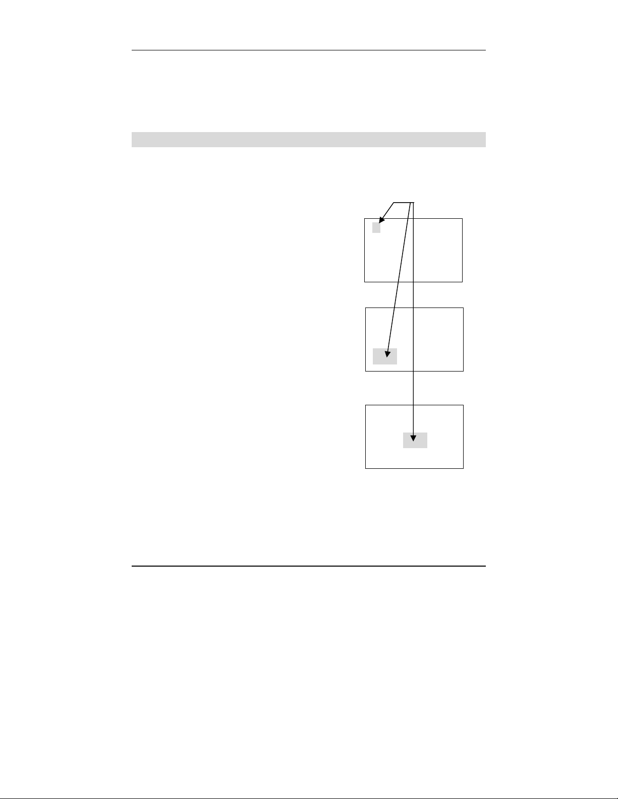
Transmitting Station
The Atomic Time Synchronization Indicator in the LCD display indicates the
status of the signal as illustrated below.
Searching
for Signal
Found
Signal
Completed Time
Synchronization
Blinking
Time
Synchronization
Failure
Automatic Reception
• The atomic clock feature will automatically start searching for time code
signals under the following conditions. (Refer to paragraph “PIX-200
Atomic Clock/Time Code Signal” at the end of this chapter for details
about reception duration)
Amano PIX-200 Operation Manual 4-1
Page 36

1) Every time you plug in the unit it will search for the signals for 15
minutes.
2) Every night starting at 1:15am until 4:00am (For 2 hours 46 minutes)
when the unit is connected to the AC adapter.
• When the time displayed on the unit is different by more than ±15 minutes
from the official standard time of the location, you can perform one of the
following actions:
1) Remove the cover and press (-) and (E)
button at the same time for two seconds.
The “L-0 USA”, “L-0 Geny (Germany)” or
“L-0 brtn (UK)” display will appear. Press
(+) button and the unit will start searching
for time code signals. The level of the
MON TUE WED THU FRI SAT SUN
△ △ △ △ △ △ △
L-688 U5A
23:59:59
▲
radio wave strength will be displayed
from “L-0” to “L-6”. “L-6” means that the radio
wave is very strong. Press the (E) button to
stop searching for time code signals.
2) Change the time manually. (Please refer to page 3-1, “Setting the
Time” , or page 3-2, “Easy Way to Set the Time).
Note:
• When the “Completed Time Synchronization” symbol is on, it means that
the unit has received the time code signal within 24 hours.
• The clock may display the wrong time. This may happen if it fails to
receive radio wave signals properly because of interference, an
inappropriate location, or bad radio wave receiving conditions. Should this
happen, move the clock to another place such as near a window where it
can receive radio wave signals.
• Please face the ribbon carriage side of the unit to the direction of the radio
wave signals.
• Even if the clock is unable to receive radio wave signals, its Quartz
mechanism will continue to keep the time.
Inappropriate places to keep the unit
Please note that the clock may be unable to receive radio wave signals
properly under the following conditions.
− Inside a large building, between tall buildings,
underground, building without windows.
− Close to overhead power lines, TV stations
and train cables.
− Close to home electrical appliances or
devices such as TV’s, PC’s, refrigerators or
fax machines.
4-2
Amano PIX-200 Operation Manual
Page 37

− Close to furniture made of steel, such as steel desk.
− In places generating radio interference, such as near construction sites,
airports or in heavy traffic.
− Inside a vehicle, train or airplane.
Setting the Atomic Clock (Germany, UK and others)
In this setup, you can select DCF in Germany, MSF in UK or disable the
Atomic Clock function. The factory default is set to DCF in Germany.
1. Unlock and remove the cover.
2. Press (+) and (E) button on top of the unit at
the same time, holding down for 2 seconds
until “SEt UP Pro9” appears on the display.
2. Press the (+) button eleven times to position
the “▲” alongside the 5
th
line down from the
upper righthand corner of the display
alongside “OTHERS” (on the label).
3. Press (E) button and you will see
“P1 LCd diSPly” display. Press (+) button
3 times to advance to “P4 CloC 5Ync”
display.
4. Press (E) button to select official standard
Atomic Clock frequency or disable the
Atomic Clock. If you are in Europe, you can
select from “GErAny” (DCF in Germany),
“britAN” (MSF in UK) or “oFF”. (Disable the
atomic clock) by pressing (-) or (+) button.
In case of other countries, you can select
either “on” or “oFF” by pressing (-) or (+)
button.
5. Press (E) button to confirm your setting and
return to “SEt UP Pro9” display
Blinking
MON TUE WED THU FRI SAT SUN
△ △ △ △ △ △ △
8SEt 8UP8
8P ro 98
MON TUE WED THU FRI SAT SUN
△ △ △ △ △ △ △
P488 CLoC
85 Yn C8
MON TUE WED THU FRI SAT SUN
△ △ △ △ △ △ △
CLC8 5ynC
9ErA Ny
MON TUE WED THU FRI SAT SUN
△ △ △ △ △ △ △
8SEt 8UP8
8P ro 98
▲
▲
▲
▲
▲
▲
▲
Amano PIX-200 Operation Manual 4-3
Page 38

Setting the Time Zone (US only)
This setup is for US only. In this setup, you can set
the time zone or select to disable the Atomic Clock
function.
1. Unlock and remove the cover.
2. Press (+) and (E) button on top of the unit at the
same time, holding down for 2 seconds until “SEt
UP Pro9” appears on the display.
3. Press the (+) button eleven times to position
the “▲” alongside the 5
upper righthand corner in the display alongside
“OTHERS” (on the label).
2. Press (E) button and you will see
“P1 LCd diSPly” display. Press (+) button
3 times to advance to “P4 CloC 5ync” display.
3. Press (E) button to set the time zone. When you
set the time zone, you need to input the
time difference from UTC (Universal Time
Coordinated). Please refer to the following chart.
Time Dif ference f rom UTC Time Zone Major Cities
-5 EST New York, Boston
-6 CST Chicago, Houston
-7 MST Phoenix , Denver
-8 PST Los Angeles, San Francisco
For example, using the chart above, t 2onE
with – 5:00 should appear on the display for
Eastern Time Zone (EST).
th
line down from the
Blinking
MON TUE WED THU FRI SAT SUN
△ △ △ △ △ △ △
8SEt 8UP8
8P ro 98
MON TUE WED THU FRI SAT SUN
△ △ △ △ △ △ △
P188 LCd8
di 5P Ly
MON TUE WED THU FRI SAT SUN
△ △ △ △ △ △ △
P488 CLoC
85 yn C8
MON TUE WED THU FRI SAT SUN
△ △ △ △ △ △ △
8t82 onE8
80:00 88
△
△
△
△
►
△
△
△
△
△
△
►
△
△
△
△
△
△
►
△
△
△
△
△
△
►
△
△
▲
▲
▲
▲
4. When you see the “t 2onE” display where the
hour is blinking, select the time difference by
pressing (-) or (+) button. Press (E)
button to confirm the setting, and go to the
“P5 End” display.
5. If you need to disable the Atomic Clock
function because of a failure to receive the
radio signal, interference, an inappropriate
location, or just bad radio wave receiving
conditions, please press (-) or (+) button
until you see “CLC SynC oFF”. Press the (E)
button to confirm the setting, and go to the
“P5 End” display.
Note: if the unit can’t receive radio signals, try moving
the unit to another place where it can receive radio signals.
4-4
Amano PIX-200 Operation Manual
MON TUE WED THU FRI SAT SUN
△ △ △ △ △ △ △
8t82 onE8
-5:00 88
MON TUE WED THU FRI SAT SUN
△ △ △ △ △ △ △
CLC8 5ynC
8o FF 88
△
△
△
△
►
△
△
△
△
△
△
►
△
△
▲
▲
▲
▲
Page 39

6. Press the (E) button again to return to the
“SEt UP Pro9” display.
PIX-200 Atomic Clock/Time Code Signal
Following is the amount of time for the PIX-200 to receive time code signals:
• When the radio wave condition is good, the clock will require
approximately 3 minutes to complete sysnchronization.
• During the automatic reception every night (from 1:15 am to 4:00 am),
it may take up to 166 minutes to complete time synchronization
depending on the radio wave reception.
• When you manually start reception, the clock will continue to search
for time code signals until this operation is discontinued. Refer to page
4-1 through 4-4 for more information about manual atomic clock
activation.
Amano PIX-200 Operation Manual 4-5
Page 40

This page intentionally left blank.
4-6
Amano PIX-200 Operation Manual
Page 41

Chapter 5: Maintenance and Troubleshooting
Ribbon Cartridge Replacement
NOTE: Before replacing the ribbon cartridge, disconnect the power plug from
the power outlet.
1. Insert the key provided and turn
counterclockwise to unlock the cover. Lift the
cover to remove.
2. Pull the two ribbon release tabs upward.
3. While holding the release tabs in an upward
position, pull the ribbon cassette out of the
cradle.
4. If the print mechanism is down and a piece
of paper cannot be inserted, unplug the
clock, then plug it back in to move the
carriage up. This will make the ribbon
installation easier.
5. Insert a new ribbon underneath the printer
head as shown.
6. Turn the knob on the cassette clockwise one
turn to take up any slack in the ribbon.
7. Check the printing quality to confirm that you
have installed the ribbon properly.
8. Reset the INK capacity gauge by pressing
the (+) and (
-) buttons at the same time for
more than 2 seconds.
9. Replace the cover.
Cleaning
For cleaning, unplug the power cord and wipe the case with a dry cloth. Do not
use any chemical solvents or oils to clean or lubricate your PIX-200. This will
damage your clock.
To clean the inside of your clock, blow it out with compressed air.
Amano PIX-200 Operation Manual 5-1
Page 42

Error Codes
In the event of an error, an error code will appear in the display. The error
codes are listed below with their possible causes and solutions. The error
code will be displayed for 2.5 seconds.
Error Code Cause
Error 02
Error 03
Error 04
Error 05
For error codes 02 through 04, unplug the clock before checking to see that
the carriage is not stuck or jammed. Also, check to see that the ribbon cables
are in good condition and that the ribbon cassette is correctly inserted in
place. After clearing any jams, plug the clock back in.
05 error code signifies that the print length should be changed by
The
adjusting the Year Digit, Type of Hour, Language type, and Digit Number.
If the error does not disappear, please contact your AMANO Cincinnati, Inc.
representative for assistance.
Home Sensor Error when starting imprint
Timing Sensor Error
Home Sensor Error when finishing imprint
Printing Length Setting Error
Note: Printing errors can be caused by the absence of grease on the printing
carriage mechanism. If this occurs, the carriage mechanism may not
slide smoothly. This movement restriction may cause the printer to
display a print error and stop working. If this occurs, apply white silicone
grease to the horizontal metal plate that the carriage mechanism slides
against. This is illustrated in the following drawing,
5-2
Place white silicone
grease here
Amano PIX-200 Operation Manual
Page 43

Chapter 6: Appendix
Diagram of preprogrammed comments and languages.
Diagram of Character Code
Japanese English Spanish French German Italian Portuguese
Monday 月 MO LU LU MO LU SG Ⅰ 1
Tuesday 火 TU MA MA DI MA TR Ⅱ 2
Wednesday 水 W E MI ME MI ME Q U Ⅲ 3
Thursday 木 TH JU JE DO GI QI Ⅳ 4
Friday 金 FR VI VE FR VE SX Ⅴ 5
Saturday 土 SA SA SA SA SA SB Ⅵ 6
Sunday 日 SU DO DI SO DO DO Ⅶ 7
January 1 JAN ENE JAN JAN GEN JAN Ⅰ 1
February 2 FEB FEB FEV FEB FEB FEV Ⅱ 2
March 3 MAR MAR MAR MAR MAR MAR Ⅲ 3
April 4 APR ABR AVR APR APR ABR Ⅳ 4
May 5 MAY MAY MAI MAI MAG MAI Ⅴ 5
June 6 JUN JUN JUN JUN GIU JUN Ⅵ 6
July 7 JUL JUL JUL JUL LUG JUL Ⅶ 7
August 8 AUG AGO A OU AUG AGO AGO Ⅷ 8
September 9 SEP SEP S EP SEP SET SET Ⅸ 9
October 10 OCT OCT O CT OKT OTT OUT Ⅹ 10
November 11 NOV NOV NOV NOV NOV NOV ⅩⅠ 11
December 12 DEC DIC DEC DEZ DIC DEZ ⅩⅡ 12
received RCVD RCVD RCBDO RECU EING RICEV RCBDO RCVD RCVD
sent SENT SENT ENVDO E NV AUSG SPED ENVDO SENT SENT
faxed FAXED FAXED FAX FAXE FAX FAX FAX FAXED FAXED
void VOID VOID ANLDO ANNUL LAGER ANNUL A NUL VOID V OID
paid PAID PAID PGADO PAYE BEZ PAGA PAGO PAID PAID
confirmed CFM ’D CFM’D CONF CONF EMPF CONF CONF CFM’D CFM’D
approved APR’D APR’D APBDO APPR B EST A PPR APRV A PR’D APR’D
completed CMPL’D CMPL’D TRMDO TERM ABGE S COMPL TERM CMPL’D CMPL’D
origin ORIGN ORIG N ORIGN ORIG ORIG ORIG ORIG ORIGN ORIGN
file FILE FILE ARCH FICH AKTE FILE ARQV FILE FILE
in I N IN ENTRA ENTRE KOMMT ENTR A ENTRA IN IN
out OUT OUT SALID SORTI GEHT USCIT SALI D OUT OUT
Used USED USED UTIL UTIL GEBRA UTIL UTIL USED USED
Roman
no.
No.
The alphanumeric characters on the upper row are for the first digit of the
code and the ones on the far left column are for the second digit of the code.
For example, if you want to program:
“(Year)(Month)(Date)(SP)(Hour)(:)(Minute)(AM/PM)(SP)(A)(M)(A)(N)(O)"
the code will be; 10, 11, 12, 20, 13, 3A, 14, 1C, 20, 41, 4D, 41, 4E, 4F
and the PIX-200 would print the following:
IMPRINT IMAGE: ‘05DEC 15 8:23AM AMANO
Note: Space characters in the bold square shown in the following illustration
will not be recognized as one-byte font (7 dots in width), but instead will
be recognized as a narrow font (5 dots in width). When “In” is placed
before the space character when changing the font size, the font will be
bigger. Please refer to the diagram showing the fonts.
Amano PIX-200 Operation Manual 6-1
Page 44

(
Space Character
d/u0 1 23456789ABCDE F
0En (Year) SP0@P`p
1 dL (Month) !1AQaq
2in (Date) "2BRbr
3 (Hour) #3CScs
4 (Minute) $4DTdt
5 (Second) 5EUeu
6
7 (Week No.) ’ 7GWgw“
8 (Julian Date) (8HXhx
9 (Number) )9IYiy\
A (Repeat Time) *:JZjz
B
C (AM/PM) , L
D - M]m} Γ LL
E . N^n~ Δ Ln
F / O_o Θ Un
(Day of the
week)
Preprogrammed
Comment)
&6FVfv‘
+;K[k{
\
l|
Ⅰ受
Ⅱ領
Ⅲ収
Ⅴ検
Ⅹ付
-
年・
月
日
平
Λ
Ξ 1 Dot SP
。
Π 2 Dot SP
「
Σ 3 Dot SP
」
Φ 4 Dot SP
、
Ψ 5 Dot SP
Æ
Ä
Ø
Ö
Ã
É
Å
Code Function
in Insert character
dL Delete character
En End of the sentence
Code Function
J Start Two-Byte
Jn Undo Two-Byte
L Start Emphatic Byte
LL Start Double-Width Byte
Ln Undo Emphatic/Double-Width Byte
Un Undo Space Character
6 Dot SP
7 Dot SP
8 Dot SP
9 Dot SP
J
Jn
L
6-2
Amano PIX-200 Operation Manual
Page 45

Diagram of Font
The maximum dots, which can fit into one line is a total of 148 dots.
Character Font Dots Character Code
I Common One-Byte 7
One-Byte Emphatic 8
Double-Width 13
II Common Two-Byte 9
Two-Byte Emphatic 10
Double-Width 17
III Special Symbols Two-Byte 9
Emphatic 10
Double-Width 17
IV Space Character + "Un"
--- 5 7
Emphatic 6 8
Double-Width 9 13
V Second One-Byte 7 15
VI AM/PM Fixed 13 1C
VII Chinese Character Fixed 10 From 90 to 98
From 10 to 89, A1 to A4
(Excluding IV,V, VI)
From A6 to B5
Characters in the Bold
Square (Refer to page 25)
Amano PIX-200 Operation Manual 6-3
Page 46

Diagram of printing type for minutes
Min 01234567892526272829303132333435515253545556575859
60 (1/60) 00 01 02 03 04 05 06 07 08 09 25 26 27 28 29 30 31 32 33 34 35 51 52 53 54 55 56 57 58 59
10 (1/10) 0000001111 44444555555 888999999
100B (5/100)
0 0 0 05 05 05 10 10 10 15 40 40 45 45 45 50 50 50 55 55 55 85 85 85 90 90 90 95 95 95
100A = One hour (3,600 seconds) is divided by 100 and the minutes are printed in a
00-99 range. The minute increments by 1 every 36 seconds and seconds are printed in
a 00-35 range.
th
60
(mins) 100A (mins)
:00 00s .00 00s
. .
:00 35s .00 35s
:00 36s .01 00s
:33 00s .55 00s
:33 01s .55 01s
. .
:33 35s .55 35s
:33 36s .56 00s
:59 24s .99 00s
. .
:59 57s .99 33s
:59 58s .99 34s
:59 59s .99 35s
The minute increments by 1
every 36 seconds
33 minutes = 33/60*100 = 55
6-4
Amano PIX-200 Operation Manual
Page 47

NOTES
Amano PIX-200 Operation Manual 6-5
Page 48

NOTES
6-6
Amano PIX-200 Operation Manual
Page 49

Page 50

(800) 526
-
255
9
Corporate Headquarters
140 Harrison Avenue, Roseland, NJ 07068-1239
www.amano.com/time
AJR-501102 • Copyright © 2012 Amano Cincinnati, Inc. • 04/12/0
 Loading...