

Page 1

TM
MTX-15
Data Collection Terminal
Installation and Operation Guide
Page 2

Thank you…
For purchasing another fine product from
Proprietary Notice
This document contains proprietary information and such
information may not be reproduced in whole or in part without
written permission from:
Roseland, New Jersey, 07068-1239
Amano Cincinnati, Inc. reserves the right to make equipment
changes and improvements that may not be reflected in this
document. Portions of this document may have been updated to
include the latest hardware or firmware version, if applicable.
We recommend that this document be read in its entirety before
any attempt is made to operate the equipment.
For more information about Amano’s complete line of time
products, visit our web site at:
Amano Cincinnati, Inc.
Amano Cincinnati, Inc.
140 Harrison Avenue
www.amano.com/time
About This Operation Guide
This Operation Guide covers the MTX-15 Terminals for use with Amano
Time & Attendance software for the following versions; Time Guardian
v5.0, Time Guardian Plus v2.0, and Time Guardian Pro v4.0.
This Operation Guide discusses:
Chapter 1: Details typical MTX-15 terminal installation.
Chapter 2: Setting up your MTX-15 terminal for use with Amano Time &
Attendance software.
Chapter 3: Details MTX-15 diagnostics.
Page 3

Table of Contents
Chapter 1: MTX-15 Installation 1-1
Unpacking Your MTX-15 ............................................................................... 1-1
Dip Switch ..................................................................................................... 1-2
Wall Mounting ............................................................................................... 1-3
Coin Battery Activation (setup retention) ....................................................... 1-5
Battery Backup for Full Power Reserve ........................................................ 1-6
Signal Relay Circuit (used to ring Bell/Buzzer) .............................................. 1-7
Communication Connections ........................................................................ 1-8
Serial Connection 1-8
Modem Connection 1-12
Ethernet Connection (Network) 1-14
MTX-15 Startup (Initialization) ..................................................................... 1-16
Chapter 2: MTX-15 Operation with Time & Attendance Software 2-1
Daily MTX-15 Use ......................................................................................... 2-3
Normal Punching at the MTX-15 terminal 2-3
View Employee Punches at MTX-15 2-4
View Employee Hours at MTX-15 2-7
Lock-In Schedule Feature 2-9
Unlock Schedule Procedure at the MTX-15 terminal 2-9
Meal Punch Procedure for MTX-15 2-11
Break Punch Procedure for MTX-15 2-12
Labor Transfer Procedure for MTX-15 2-13
MTX-15 Terminal Communications ............................................................. 2-15
MTX-15 Setup with Amano Time & Attendance Software 2-16
Time & Attendance Software Communications Module 2-26
Chapter 3: MTX-15 Diagnostics 3-1
Running Diagnostics ..................................................................................... 3-1
Relay, Keypad, LED and Buzzer Test 3-2
Reader Test 3-3
Screen Test 3-4
Network Configuration 3-4
Invalid Network Settings 3-6
Contrast Adjustment 3-6
Specifications ................................................................................................ 3-7
MTX-15 Installation & Operation Guide i
Page 4

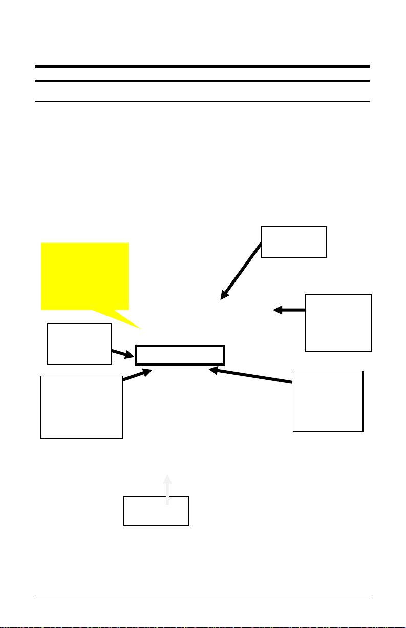
Basic Installation for Time Guardian MTX-15/A300 Package
Step 1 – Unlock and remove the
rear terminal back plate. Connect the
MTX-15 terminal using direct connect,
Ethernet, or modem cable, and host
PC. Plug MTX-15 into AC power to
power up.
Step 2 – Install Time Guardian
Software on the host PC. The
installation should start automatically,
but if it stalls, browse on CD to
\Disk1\InstData\Windows\VM\install.exe
Step 3 – Perform software activation by entering
the Serial Number and perform on-line registration for
Time Guardian.
Note: QuickBooks® integration is available, but it
needs to be setup in Time Guardian. Also,
QuickBooks must be installed on the same host
computer and running.
Step 4 – perform the Wizard Setup for Time
Guardian and end by pressing
Note: integration and synchronization will occur with
employee transfer from Time Guardian when the
MTX-15 terminal is polled.
Note: Other installations, i.e. with FPT40 terminal, with Time
Guardian Plus, or with Time Guardian Pro may be slightly
different. This procedure of connecting the MTX-15 terminal
utilize examples with Time Guardian software.
button.
ii MTX-15 Installation & Operation Guide
Page 5
Chapter 1: MTX-15 Installation
Unpacking Your MTX-15
In addition to this guide, your package should include the following:
MTX-15 Data Collection Terminal with AC Adapter
1 set of Keys (2)
Time Guardian CD (only included with MTX-15/A300 package).
CommStik 50 ft cable (only included with MTX-15/A300 package).
6 ft. Ethernet cable (only included with MTX-15/A302 package).
*AA Batteries for power backup are not included
Front View
Soft Function
Buttons
Downloaded
from Software
Function
Buttons
Display
Magnetic
Card
Reader
Green LED
will flash
here.
Red LED
will flash
here.
Keypad
Figure 1: MTX-15 Front View
MTX-15 Installation & Operation Guide Page 1-1
Page 6
Note: The date and time in the desired format (e.g., military or
AM/PM) are downloaded from the Time & Attendance
software. The software will also control DST and any offset
(TZ). Also downloaded to the terminal for display are the
employee hours and last 4 punches.
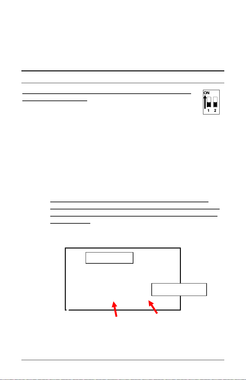
Dip Switch
The Dip Switch on the MTX-15 PCB in most instances should
not have to be changed from the default factory setting, which
is both S1 and S2 set to ON as follows:
Switch 1: Enables the termination resistor (ON position).
When RS-485 serial communications are used and the terminal i s
located at the end of the serial chain, this switch should be ON. It
should also be ON for Modem and Network terminals. For all RS-485
terminals except the last one, this switch should be OFF.
Switch 2: Disables RS-485 communications (OFF position) in order
to permit firmware upgrades via RS-232 (serial models only). For
normal operation, this switch should always be in the ON position.
Note: Firmware upgrades should never be attempted without
consulting Amano Technical Support for detailed instructions.
Data should always be polled from the Amano Time &
Attendance Software before updating the firmware on the
terminal as the current punch information at the terminal
could be lost.
The following Figure illustrates the DIP switch location on the MTX-15
PCB relative to other MTX-15 PCB components.
Reset Button
Coin Battery Signal Relay Contact Serial Port
Figure 2: MTX-15 PCB Component Location
Note: The Dip Switch, Signal Relay Output and AC Power Adapter
cord can be found at the same location on all MTX-15 models.
Page 1-2 MTX-15 Installation & Operation Guide
Page 7

Wall Mounting
Warning! Before selecting a mounting location for your MTX-15, you
must consider the following:
The mounting surface and hardware must be able to support the
unit’s weight, 6 lbs. (2.7 kg).
The area must be within the specified operating temperature range.
Close proximity to a power source or wall outlet.
The area or wall can accommodate signal and/or power conduits.
Note: Wiring can be routed through either cable feed.
Note: If you are using rigid (1/2” EMT) conduit, secure the conduit to
the bottom cable feed using two nuts, making sure the pipe
doesn’t extend beyond the thickness of the nut. Do not bend
the cable feed.
Amano recommends the following procedure for wall
mounting:
Step 1. Insert the key into the keyhole, turn clockwise, and remove the
back plate as shown (see Figure 3). Set the terminal face up
on a flat surface. Do not remove the key.
Figure 3: Rear Back Plate Removal
Step 2. Using the back plate as a template, mark the location of the
upper mounting hole on the wall. Mark a vertical line on the
wall as a guide to align the lower mounting hole.
MTX-15 Installation & Operation Guide Page 1-3
Page 8
Step 3. Install a screw or anchor at the mark and hang the back plate
from the top-mounting hole. Level the back plate by centering
the vertical line in the bottom hole (see Figure 4).
Step 4. Mark the location of the bottom hole.
Step 5. If using the square Cable Feed hole in the Backing Plate for
power or communications, mark this location (see Figure 4).
Step 6. Install another screw or anchor for the bottom-mounting hole
and secure the back plate to the wall.
Note: The Rest Slots on the terminal slip over the Rest Hooks (see
Figure 4) on the Back Plate to hold the terminal in the open
position for wiring and configuration, such as connecting to the
signal relay to ring a bell (see Figure 7).
Square Cable
Feed Hole
Rest Hooks &
Rest Slots
Keylock to
Unlock Back Plate
Note: Please connect all the desired communications wiring now with
Figure 4: MTX-15 Terminal on Rest Hooks
the back plate off.
Page 1-4 MTX-15 Installation & Operation Guide
Page 9

Coin Battery Activation (setup retention)
Once the terminal back plate has been removed the coin battery should
be activated with the terminal face down, by pulling and removing the
green paper insulating strip from under the coin battery (see Figure 5).
This battery is used to maintain time/date setup.
Coin
Battery
Insulating
Strip
Figure 5: Coin Battery Insulating Strip
Note: If the insulating strip is not removed or the button battery is
bad the following error and message may appear on the
display:
Figure 6: Coin Battery Error
MTX-15 Installation & Operation Guide Page 1-5
Page 10
Battery Backup for Full Power Reserve
Once the terminal back plate has been removed the 6 disposable AA
batteries should be inserted in the battery slots in the correct position
[polarity] (see Figure 7). These batteries are used to provide emergency
full power reserve for a limited time should AC power to the terminal be
interrupted. During this type of emergency the terminal will maintain full
function utilizing the power from these batteries to let employees in or
out. However, the amount of reserve power provided by these batteries
corresponds to the battery level as these batteries are disposable and
not charged by the MTX-15. Also, the battery life can be reduced by the
type of MTX-15 (i.e., the Ethernet MTX-15 requires the most power). The
function of these batteries should not be confused with the coin battery
function, which maintains power to the flash memory for setup and
transactions.
Coin
Battery
AA
Battery
Placement
Figure 7: AA Disposable Battery
Note: Depleted AA batteries can leak which could lead to MTX-15
PCB corrosion and damage.
Page 1-6 MTX-15 Installation & Operation Guide
Page 11
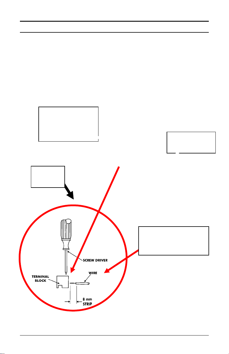
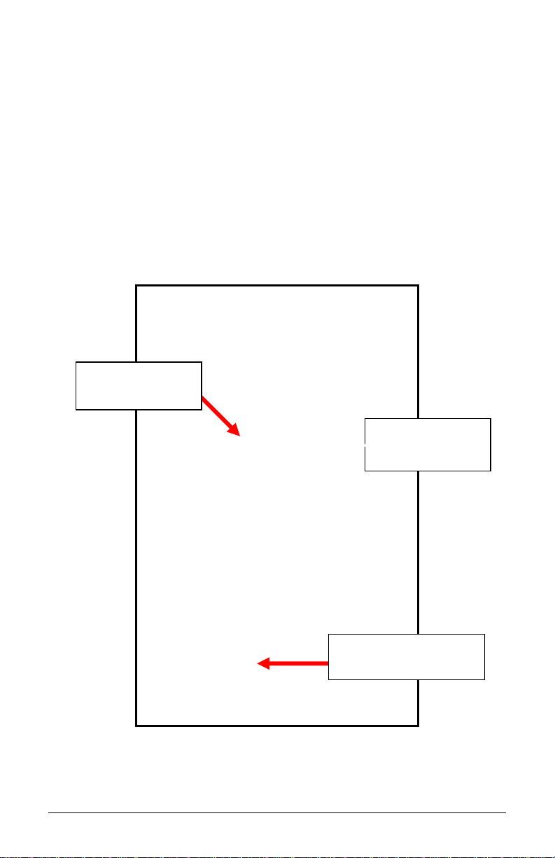
Signal Relay Circuit (used to ring Bell/Buzzer)
Warning! All connections to the relay contacts must be Class 2 wiring
with a maximum of 24 VDC, 1A.
The MTX-15 is equipped with one (1) NORMALLY OPEN (NO) relay
contact that can be used to control external equipment such as a bell or
buzzer. Connection to the contacts is via the screw terminal block
located on the back panel PCB alongside the serial connector. The
terminal block can be removed from the PCB to facilitate wiring
(see Figure 8). If removed, once connections are made, carefully
re-install the terminal block.
Relay Circuit
Terminal Block
Removed from
PCB.
Coin
Battery.
Serial
Connection.
Connections to the
relay contacts are
made as follows.
Figure 8: Signal Relay Circuit Location & Connection
MTX-15 Installation & Operation Guide Page 1-7
Page 12
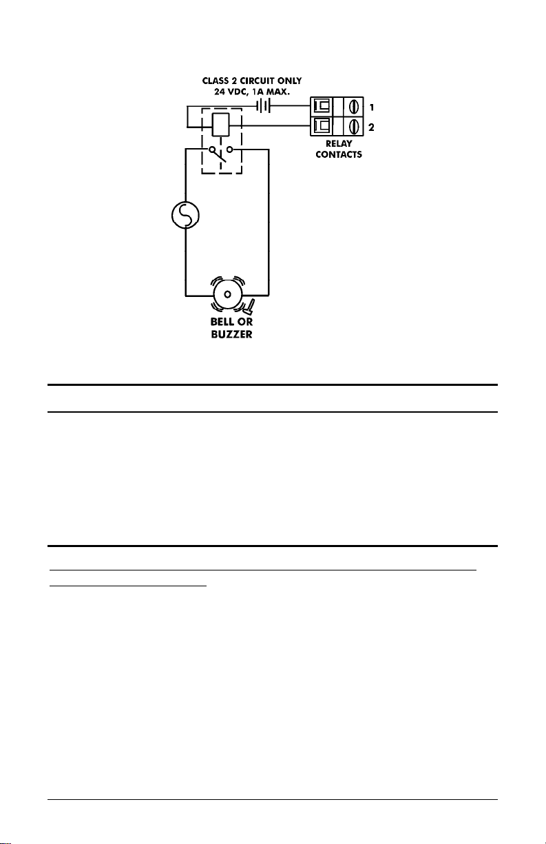
A typical wiring diagram for a bell circuit is shown below:
Communication Connections
Connections between your Host PC and MTX-15 terminal(s) are based
upon the model of the MTX-15 terminal you have purchased (SerialDirect, Ethernet-network, or Modem).
Serial Connection
Use the CommStik™ (50 foot RJ-11 to USB) communications cable to
interface with the host PC. This part comes standard with the Time
Guardian MTX-15/A300 package. If you purchased the terminal
separately, Amano recommends that you use Amano AUS-10065x
CommStik™ (50 foot RJ-11 to USB) Communications Cable to interface
with the host PC.
RS-485 communications can be used for systems requiring up to 31
terminals. You will require the following accessories for each additional
RS-485 terminal:
AMX-206950: Communications Cable – 10’, 6 conductor RJ-11
AMX-206700: Junction Box
Page 1-8 MTX-15 Installation & Operation Guide
Page 13
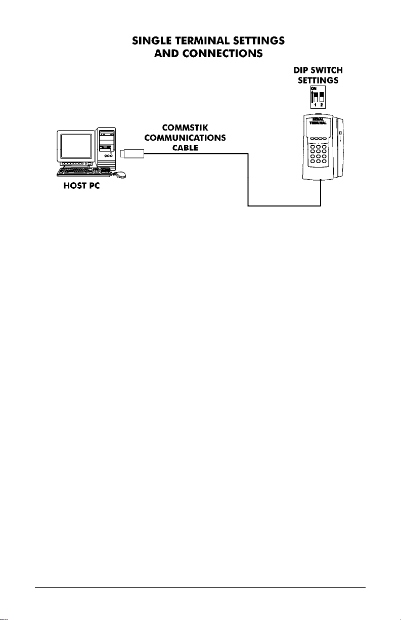
Note: When there is only one RS-485 MTX-15 terminal in the
system, DIP Switch 1 must be in the ON position to enable the
termination resistor.
Note: If the distance between the terminal and the host PC is more
than 50 feet, two junction boxes will be required (see the next
page), or you can use an RJ-11 coupler with a RJ-11
extension cable, not to exceed 3,950 feet.
Multi-terminal (maximum of 31) applications require the DIP Switches to
be OFF in all but the last terminal on the communications line. DIP
Switch 1 of the last terminal must be set to ON to enable the termination
resistor so that all the terminals can properly communicate with the Host
PC. The terminal settings and connections between the PC and
terminals for this application are as follows:
MTX-15 Installation & Operation Guide Page 1-9
Page 14
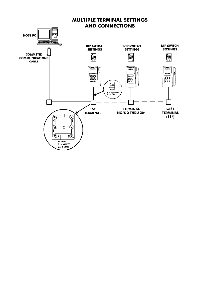
*The maximum number of terminals is dependent upon the distance and
the quality of cabling used. It is recommended that Belden Low Voltage
Computer Cable, P/N 9841 or equivalent be used to connect the junction
boxes for this application.
Warning! Please note that terminal #3 (used for the RS-485 cab le
Shield) is disconnected from the internal RJ-11 receptacle
of the junction box. This is deliberate; the shield connection
is NOT fed through to the MTX-15 Terminal.
Page 1-10 MTX-15 Installation & Operation Guide
Page 15

A
Interior View with Back Plate Removed
RJ-11 Jack
(RS-232/485)
from CommStik
Connected to
USB-Serial Port.
Signal
Relay
Output.
DIP Switch
and Reset
Button.
C Power.
Figure 9: Serial Connection to MTX-15
MTX-15 Installation & Operation Guide Page 1-11
Page 16
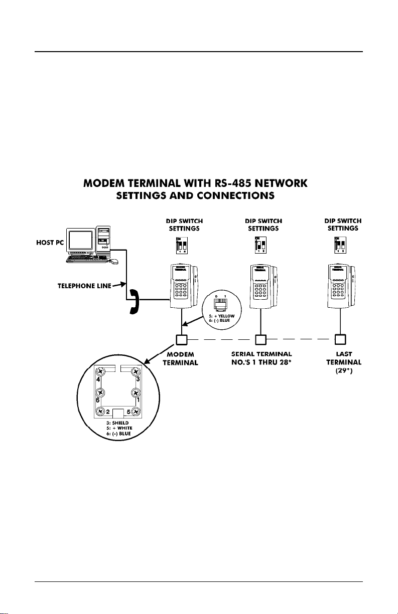
Modem Connection
The dial-up modem communication is generally used when the host PC
is located at a different facility from the terminal(s). This configuration can
consist of a single MTX-15 Modem Terminal, or an MTX-15 Modem
Terminal networked (via RS-485) with a group of up to (29) Serial
MTX-15 Terminals.
The Modem Terminal is connected to a standard telephone line. The
terminal settings and connections between the Modem Terminal and
Serial Terminals are as follows:
Note: The serial connections depicted in the above illustration are
the same as for the RS-485 wiring described previously.
Page 1-12 MTX-15 Installation & Operation Guide
Page 17

Interior View with Back Plate Removed
RJ-11 Jack
for Serial
Port (Not
Used).
RJ-11 Jack
for Modem
(Plug Phone
Line In).
Figure 10: Modem Connection to MTX-15
MTX-15 Installation & Operation Guide Page 1-13
Page 18
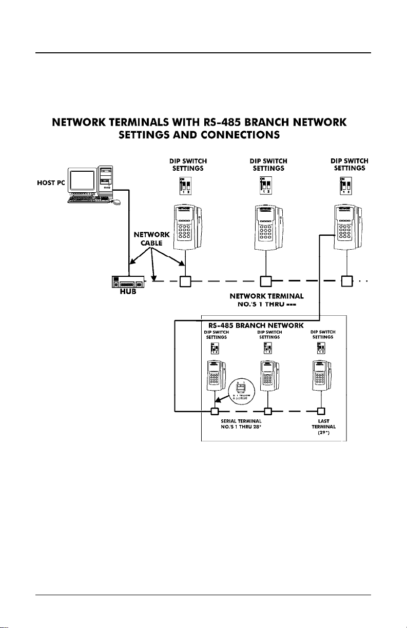
Ethernet Connection (Network)
Network Terminals can be connected to a standard 10BaseT or 100
BaseTx computer network. In addition, each Network Terminal can have
a group of up to 29 Serial Terminals networked via RS-485 (in the same
manner described previously for a Modem Terminal).
Note: The serial connections for the RS-485 branch network are the
same as for the RS-485 wiring described previously.
Page 1-14 MTX-15 Installation & Operation Guide
Page 19

Disposeable
AA Batteries
for Backup
Power for
Display and
Reader
Interior View with Back Plate Removed
Connect
RJ-45 Jack
for Ethernet
Cable Here
[on Digi™]
MAC Address
Located Here
Figure 11: Ethernet Connection to MTX-15
Note: Failure of the AA Batteries will not
transaction and setup data stored in the flash memory of the
terminal, provided the coin battery is enabled (see page 1-5).
cause the loss of any
MTX-15 Installation & Operation Guide Page 1-15
Page 20

MTX-15 Startup (Initialization)
Once connections have been made and the terminal back plate has
been mounted on the wall, the MTX-15 terminal can be initialized. To do
so perform the following:
Step 1. Re-install the MTX-15 terminal on the back plate by placing the
notch on the bottom of the Back Plate (see Figure 3) over the
plastic tab in the bottom of the terminal cabinet. Pivot the
terminal up so the locating pin on the Back Plate aligns with its
corresponding hole in the cabinet. Rotate the key
counterclockwise to lock the terminal in place. Remove the
key.
Step 2. Plug in the terminal AC power adapter into an outlet. The
terminal will beep and do the following:
Test memory banks “0” through “6” and display the results.
Figure 12: Initial Memory Bank Test
Note: After this test has been initially performed, the 0 thru 6 screen
will not appear on startup
Display the serial number of this terminal.
Display the terminal communication type: serial (RS232/RS485),
Modem or Ethernet.
Test the keypad and if OK, display the keypad version.
Display the version of firmware installed.
Display the Terminal Number (TN always defaults to “0” until
re-assigned by the Time & Attendance Software).
unless the coin battery fails.
Page 1-16 MTX-15 Installation & Operation Guide
Page 21

Figure 13: Terminal Status
After display of terminal status, the initial startup display will
appear with January 1, 2000, 12:00 am. Also no function buttons
will be displayed until the terminal is downloaded from the host.
Figure 14: MTX-15 Initial Startup Display
Note: The time and date cannot
downloaded to the terminal using the Time & Attendance
software from the host PC. Pressing any numeric key will
display a flashing “E04 Keypad Lock” on top. All MTX-15
terminal features and functions must be enabled from the host.
Step 3. Once the default time is displayed (see Figure 14), you can
swipe a badge to verify that the badge reader is working. The
badge number will be displayed at the top of the screen.
Step 4. Please insert the Amano Time & Attendance Software CD into
the CD-ROM drive of your PC to install the software. See the
next Chapter for additional details on using your MTX-15
terminal with the Amano Time & Attendance software.
be set from the keypad; it must be
MTX-15 Installation & Operation Guide Page 1-17
Page 22

This page intentionally left blank.
Page 1-18 MTX-15 Installation & Operation Guide
Page 23

Chapter 2: MTX-15 Operation with
Time & Attendance Software
The MTX-15 is a data collection terminal to record the time attendance
information, which is integrated with the Amano Time & Attendance
software such as Time Guardian, Time Guardian Plus and Time
Guardian Pro for further data processing. The MTX-15 terminal enables
an employee to swipe a magnetic badge card, use a proximity reader, or
enter his/her badge number and other information. It has a 12 button
numerical keypad to enter the badge number with 4 additional function
buttons for operation, configuration, or Diagnostics (see Chapter 3). The
terminal has a graphical LCD display to show the current date/time and
other information depending upon the mode. The terminal can be
powered through the AC power adapter or utilize backup power from AA
batteries (not included). It can be connected to the host Time &
Attendance computer by modem, serial-direct, or Ethernet-network
interface. The MTX-15 Data Collection Terminal can support:
12 Digit Badge Number: The MTX-15 supports a 12 digit
employee badge number. When the MTX terminal bar code or
mag card reader reads a card, it reports 8-digits to the software.
However, a proximity card will report 12-digits.
View Punch Information: The MTX-15 allows the user to view
the last 4 punches on any MTX-15 terminal in a multiple terminal
configuration. The Time & Attendance software will download the
last 4 punch data of each employee to each MTX-15 terminal at
a predetermined time every night. Each terminal will hold the last
4 punch information in its memory for all employees in the table.
The user can view the last 4 punches from the main screen as
shown in Figure 19.
Note: The latest punch will replace the last punch and be displayed
only at the terminal where the punch occurred. All other
terminals will have to be polled by the Time & Attendance
software to get updated punch information.
View Hour Information: The MTX-15 allows the user to view the
number of hours on any MTX-15 terminal in a multiple terminal
configuration. The Time & Attendance software will download the
number of hours in each different pay category for each
employee to each MTX-15 terminal at a predetermined time.
Each terminal will hold the hour information in its memory for all
employees in the table. The maximum type of the hours will be
MTX-15 Installation & Operation Guide Page 2-1
Page 24

limited to 5. The host software will decide the number of hours
that should be downloaded and the text label for each hour type.
The user can view this information from the main screen as
shown below.
Lock-In Schedule: The MTX-15 supports the ability to restrict
the employee to a certain time period. The schedules are
configured and downloaded from the Amano Time & Attendance
software. Each employee can have his/her own schedule for
each day with a grace time period configured for all employees
through the software. The terminal will allow the user to punch
during the grace period. For example, if there is a 15 minute
grace period for start time and a 30 minute grace period for end
time, the terminal will allow the user to punch between 7:45AM to
5:30PM for a normal 8:00AM – 5:00PM schedule. Once this time
period is expired, the terminal will restrict the user from making a
punch on the terminal.
Unlock Schedule: If the employee has passed the scheduled
time to punch, the supervisor has the ability to unlock the
schedule to allow the employee to punch. When the employee
table is downloaded, there is one field that distinguishes between
the regular employee and the supervisor. Only a supervisor is
allowed to override the schedule so the employee can punch.
Note: Previous versions of the Amano Time & Attendance software
cannot enable all the discussed features on the MTX-15
terminal. These previous versions are;
Time Guardian v4.0 or lower.
Time Guardian Plus v1.0.
Time Guardian Pro v3.7 or lower.
2-2 MTX-15 Installation & Operation Guide
Page 25

Daily MTX-15 Use
Normal Punching at the MTX-15 terminal
The MTX-15 firmware supports a 12 digit badge number so the terminal
will always expect the user to press the enter
entering the badge number and it will prefix the badge number with
zeroes if it is less than 12 digits. For example, if the user enters “1234”
for a badge number and presses the enter
will be treated as “000000001234”.
button after
button, the number
Swipe
badge or
use the
keypad
to enter
ID to
punch.
When the user enters a valid employee ID with the keypad and/or swipes
a valid badge, the Last and First name (see Figure 15) of the employee
will appear in the display if that ID is associated with a name in the Time
& Attendance software.
Figure 15: Normal Punch Display at Terminal
MTX-15 Installation & Operation Guide Page 2-3
Page 26

Note: The terminal contains repunch protection. An
error message, “E03 Only one” will appear if you try
to punch more than one within 3 minute period.
Note: All employee information such as hours, punches, and unlock
schedule is always displayed at the MTX-15 terminal in military
time format (i.e., 5:00PM = 17:00). However, the clock time
displayed is controlled by the settings in the Amano Time &
Attendance software, which can be set to either AM/PM or
military.
Note: When performing View Punches, View Hours, and Unlock
Schedule the same error messages can appear for invalid
punch, etc.
View Employee Punches at MTX-15
The user should be on the main screen as shown below to access the
employee punch information. The terminal will always timeout within 3
seconds of no activity and return to the normal display.
Figure 15: MTX-16 Normal Startup Display
Note: The function buttons shown in Figure 15 will only appear after
successful download with Amano Time & Attendance software.
The coffee break options must be enabled in the Time &
Attendance software for these function buttons to be active.
Step 1. From the normal main display (see Figure 16) press the menu
button on the left to view employee information
(see Figure 17). From this screen, use the Back
button
to exit and return to the main display.
2-4 MTX-15 Installation & Operation Guide
Page 27

Figure 17: View Employee Punches
Step 2. Use the Function buttons (see Figure 17) as indicate d
underneath the display to move Up
highlight “View Punches” and press enter to select
and the screen will change to the following (see Figure 18).
or Down to
Figure 18: Enter ID for Punches
Step 3. The user can swipe his/her badg e magnetic card or use the
keypad to enter the ID number. Press enter
the ID number. If a mag card is used, there is no need to press
enter
recorded for that ID with the employee name (see Figure 19).
. The terminal will display the last 4 punches
to accept
Figure 19: View 1st Page of Punches at Terminal
Use the Down
punch at the terminal (see Figure 20 for an example).
function button to scroll down to view the 4
th
MTX-15 Installation & Operation Guide Page 2-5
Page 28

th
Figure 20: Scroll Down to View 4
Note: The terminal will display the punch information if a valid ID is
entered and it finds the ID in the employee table in the
terminal. The following error message will display for invalid
entry;
Punch
“E00 ID NOT Found”
All the punch information is not communicated in real time with
the terminals from the Time & Attendance software, so the
terminal will show the last 4 punches as of yesterday.
However, the terminal where the punch occurred will
actually be the latest punch.
Note: The feature to View Punches, View Hours, and Unlock
Schedule is enabled or disabled in the Time & Attendance
software. If View Punches is disabled in the Time &
Attendance software the following error message will appear
for an entry;
“E08 NOT Allowed”
If the feature is enabled but there is no data downloaded from
the host Amano Time & Attendance software, the following
message will be displayed;
“NOT Available”
If there is no activity by the user (no key press, badge swipe,
etc.) after entering this mode in 3 to 9 seconds, the terminal
will timeout and exit this mode and return back to the normal
main screen.
2-6 MTX-15 Installation & Operation Guide
Page 29

View Employee Hours at MTX-15
The user should be on the main screen to access the employee hour
information.
From the normal main display press the menu
button on
the left to view employee information choices (see Figure 21).
Figure 21: View Hours at Terminal
Use the Function buttons as indicated underneath the display
to move Up and Down to highlight “View Hours” and
press enter
change to the following (see Figure 22).
on the keyboard to select and the screen
Figure 22: Enter ID for Hours
The user can swipe his/her badge magnetic card or use the
keypad to enter the ID number. Press enter
the ID number. The Time & Attendance software will download
the numbers of hours worked in the pay period for each
different category setup for each employee to all the MTX-15
terminals at a predetermined time every night. The date that
the last download occurred will be displayed “As of
MM/DD/YYYY” (see Figures 23 and 24). Each MTX-15
terminal will store the hour information for all employees in that
location. The hours worked depends on the Time &
Attendance software setup.
to accept
MTX-15 Installation & Operation Guide Page 2-7
Page 30

Figure 23: First Page of Employee Hours at Terminal
To see the 2nd page of an employee’s hours, press the Down function
button.
Figure 24: Second Page of Employee Hours at Terminal
Where the display, for example, might show depending upon what
has been defined in the Time & Attendance software:
REG = REGULAR HOURS
OT1 = OVERTIME1
OT2 = OVERTIME2
SCK = Sick Time
VAC = Vacation Time
Note: The terminal will display the hour information if a valid ID is
entered and it finds the ID in the employee table in the
terminal. The same error messages will displayed as shown for
View Punches.
Note: All the hour information is not communicated in real-time with
the terminals and the Time & Attendance software, so the
terminal will show the hours as of the date displayed.
Press the Back function button or esc key to
return to the previous menu.
2-8 MTX-15 Installation & Operation Guide
Page 31

Lock-In Schedule Feature
The new MTX-15 firmware has the ability to restrict the employee to a
scheduled time period. For example, depending on the schedule an
employee will not able to punch before 8:00AM and after 5:00PM,
Monday thru Friday.The schedules can be configured and downloaded
from the host Time & Attendance software. Each employee will have
his/her own schedule for each day. See the Time & Attendance Software
User Guide for additional information about Schedules.
A grace period for the lock-in schedule feature can be defined in the
Time & Attendance software. If a grace period is defined it will affect all
employees and all schedules on the terminals that have the lock-in
schedule feature enabled. If some terminals have this feature disabled
then it will not be active on those terminals.
For example, an enabled lock-in schedule of 08:00am to 05:00pm with a
grace period of 15 minutes for Start and End times would allow an
employee to successfully punch from 7:45am to 5:15pm. The following
error message will appear for invalid punch due to lock-in schedule rules:
“E07 ScheduleLock”
Unlock Schedule Procedure at the MTX-15 terminal
The MTX-15 firmware supports the ability to restrict invalid employee
punching times. The following procedure can be used at the terminal to
override lockout and allow an employee to punch. For example, an
employee might be asked to work on Saturday and need supervisor
assistance to punch.
For successful procedure, the Supervisor will need his/her
badge:
Step 1. From the normal main display press the menu button on
the left to view employee information choices (see Figure 25).
Figure 25: MTX-15 Unlock Schedule at Terminal
MTX-15 Installation & Operation Guide Page 2-9
Page 32

Step 2. Use the Function buttons (see Figure 25 as indicated
underneath the display to move Up
highlight “Unlock Schedule” and press enter on the
keyboard to select. The screen will change to the following
(see Figure 26).
and Down to
Figure 26: Swipe Supervisor Badge
Step 3. A user with supervisor rights must swipe his/her badg e
magnetic card to unlock the terminal and the screen will
change to the following (see Figure 27).
Figure 27: Employee Hours at Terminal
Note: The terminal will display the Supervisor name and Schedule
Unlock if a valid badge is swiped and it finds the ID in the
employee table in the terminal. The same error messages will
displayed as shown for View Punches.
Step 4. The screen will change to the normal main screen to allow the
user who was locked out to punch. The user must punch
within 10 seconds. After a successful punch or the 10 second
timeout the employee lock-in schedule will be re-enabled.
Note: The employee lock-in schedule feature and supervisor ID’s are
all configured in the Time & Attendance software and
downloaded to the terminals when they are polled.
2-10 MTX-15 Installation & Operation Guide
Page 33

Meal Punch Procedure for MTX-15
The user should be on the main screen as shown in the example Figure
to access the employee Meal punch function. The Meal button box must
be checked on the Time & Attendance Terminal Options screen (see
page 2-24) for this function button to be active on the MTX-15 terminal.
Step 1. From the normal main display (see Figure 28) press the meal
Figure 28: MTX-15 Normal Startup Display
function button to enter an employee ID for a meal
punch (see Figure 29).
Figure 29: Enter ID for Meal Break
Step 2. The user can swipe his/her badg e magnetic card or use the
keypad to enter the ID number. Press enter
the ID number when using the keypad. If the ID is valid for that
terminal, the screen will change to display name [if a name
exists] and allow meal punch (see Figure 30).
to accept
Figure 30: Enter Meal Punch
MTX-15 Installation & Operation Guide Page 2-11
Page 34

Note: The terminal will allow the meal punch if a valid ID is entered
and it finds the ID in the employee table in the terminal. The
following error message will displayed for invalid entry.
“E00 ID NOT Found”
Note: If the ID fails the validation rule, the screen will display the
following error message.
“E03 ID Only One”
Step 3. Press the Back function button or esc key to
return to the previous menu.
Break Punch Procedure for MTX-15
The user should be on the main screen as shown in the example Figure
to access the employee Break punch function. The Break button box
must be checked on the Time & Attendance Terminal Options screen
(see page 2-24) for this function button to be active on the MTX-15.
Step 1. From the normal main display (see Figure 31) press the break
Figure 31: MTX-15 Normal Startup Display
function button to enter an employee ID for a break
punch (see Figure 32).
Figure 32: Enter Employee ID for Break
2-12 MTX-15 Installation & Operation Guide
Page 35

Step 2. The user can swipe his/her badg e magnetic card or use the
keypad to enter the ID number. Press enter
the ID number when using the keypad. If the ID is valid for that
terminal, the screen will change to display name [if a name
exists] and display the 2
nd
row with Coffee and Break function
buttons under the first row of buttons (see Figure 33).
to accept
2nd row of
function
buttons will
appear.
Step 3. At this point choose to punch for a coffee break by pressing
Figure 33: Select Coffee or Break Function
the Coffee function
regular break by pressing the break
button or choose to punch for a
function button.
Note: The terminal will not display this 2
nd
row of buttons if the coffee
and/or break function is not enabled in software Terminal
Options setup (see page 2-24).
Labor Transfer Procedure for MTX-15
The user should be on the main screen as shown in the example Figure
to access the employee labor transfer function. The Labor button MUST
be selected on the Terminal Options screen in the Time & Attendance
software (see page 2-24) for the transfer function to appear on
the MTX-15 and be active.
Figure 34: MTX-15 Normal Startup Display
MTX-15 Installation & Operation Guide Page 2-13
Page 36

Step 1. From the normal main display (see Figure 34) press the
transfer
function button to enter an employee ID for a
labor transfer (see Figure 35).
Figure 35: Enter Employee ID for Transfer
Step 2. The user can swipe his/her badg e magnetic card or use the
keypad to enter the ID number. Press enter
the ID number when using the keypad. If the ID is valid for that
terminal, the screen will change to display name [if a name
exists] and display the JOB1, JOB2, JOB3, and JOB4 function
buttons under the first row of buttons (see Figure 36).
to accept
Step 3. At this point choose the Labor Level to transfer by pressing the
appropriate JOB function button. There are 6 Labor levels that
can be defined in the Amano Time & Attendance software, but
only 4 JOB fucntion buttons will appear on the MTX-15.
However you can choose to assign more than one labor level
to a JOB function button. Also, the labor level name will appear
after the JOB fucntion button has been pressed (see Figure ) if
a labor level has been defined in the Time & Attendance
software (see page 2-25) and transfered to the terminal.
Figure 36: Select JOB for Transfer
Figure 37: JOB1 Selected for Labor Level 1
2-14 MTX-15 Installation & Operation Guide
Page 37

Step 4. If the function button has more than one labor level, use the
function keys to move Up
desired labor level. At this point use the keypad to enter the
department number [4 digits maximum] to transfer to the Labor
Level (in this example Level 1). Press the Save
button to save the transfer. From this screen, use the Back
button to exit and return to the main display.
and Down to highlight the
function
Note: This operation is controlled by configuring the Time &
Figure 38: Labor Level 1 Department Number Entered
Attendance software and downloading the information to the
MTX-15 terminal. An invalid department number entry will
cause the following error message tol appear at the bottom of
the display:
“E01 Invalid num.”
MTX-15 Terminal Communications
The Communications module in the Time & Attendance software is
used to communicate with MTX-15 terminals when setup. Locations and
terminals can be configured utilizing the Time & Attendance software
Clock tab in the Setup Wizard. Operations from this module include
polling, downloading, setting the time, and viewing specific terminal
settings in a location. Polling, or polled operation, refers to actively
sampling the status of the external terminals by the client Time &
Attendance program. Downloading is utilized to send data to the remote
terminals from the Time & Attendance software.
Note: All operations at the clock including time and employee ID’s
are controlled by downloading information from the Time &
Attendance software.
The following sections describe how to setup the Amano Time &
Attendance Software to communicate with the MTX-15 terminal for
normal time and attendance functions.
MTX-15 Installation & Operation Guide Page 2-15
Page 38

MTX-15 Setup with Amano Time & Attendance Software
Note: Prior to commencing with the Time & Attendance software
Setup Wizard, Amano recommends that you install the MTX15 terminal(s), using this MTX-15 Terminal Installation and
Operation Guide. The MTX-15 terminal is installed to
communicate with your PC/Time & Attendance software. You
may need to obtain the IP address for each Ethernet MTX-15
terminal(s) connected to the system. Also, see the section on
“Network Configuration” for how to obtain an automatic IP
and/or enter a specific IP in your MTX-15 terminal.
During the installation and setup of the Time & Attendance software the
Setup Wizard for Step 8: Clock Setup is optional;
Figure 39: Clock Setup from Time & Attendance Software
2-16 MTX-15 Installation & Operation Guide
Page 39

Use Step 8 if:
Do you have Terminals other than Access Control Terminals?
If Yes, the Time & Attendance software will automatically poll and upload
punches from connected MTX-15 terminals each time the software is
opened.
If No, the connected MTX-15 terminals will have to be polled manually
using the Communications module in the Time & Attendance software.
Do you want to configure Terminal Validation?
If Yes is selected for Terminal Validation, click the Terminal Validation
button and the Terminal Validation screen will appear (see Figure 40).
Terminal validation provides employee filtering from the setup configured
in the General, Department, and Employee tabs in the Time &
Attendance software.
Terminal Validation is used to assign employees and Labor Levels to
specific MTX-15 terminals in the system. When validation is used, only
employees assigned to a particular terminal with the selected Labor
Levels can use that terminal. Labor transfers at the terminal can only
occur within the selected Labor Levels. Terminal Validations are
downloaded to the selected MTX-15 terminals by location from the
Communications module. To do so, see the Time & Attendance Software
User Guide for more detailed information:
Figure 40: Software Setup for Terminal Validation
MTX-15 Installation & Operation Guide Page 2-17
Page 40

Do you want to configure Bell Schedules?
If Yes is selected for Bell Schedules, click the Bell Schedule button for
the Bell Schedules screen (see Figure 41).
Figure 41: Software Setup for Bell Schedules
Special Note:
Selecting Holidays will only work with HandPunches
(all HandPunch models).
A Bell schedule requires you to enter the Duration for the bell to ring, the
time of day for the bell to ring and the days of the week. Multiple entries
can be made for Bell Schedules with different duration and day
assignments. Bell Schedules are downloaded to the selected MTX-15
terminals by location by using the Communications module in the Time
& Attendance Software. To do so, see the next section and/or Time &
Attendance Software User Guide for more details.
2-18 MTX-15 Installation & Operation Guide
Page 41

Do you want to configure your Terminals?
Answer Yes to this question if you are using terminals such as a MTX-15
terminal via a serial, Ethernet, or modem connection.
Direct (serial) Connection
If Yes is selected, and a Direct connection
USB/serial cable is desired, you can just use the “MTX-15 Default”
location. You do not have to do anything else. The MTX-15 terminal, if
connected, will automatically be detected upon login.
Note: The default terminal connection is for a USB (serial-direct)
MTX-15 Terminal.
Ethernet (network) Connection
If Yes is selected, and you are installing an Ethernet connection
MTX-15 click on the Location/Terminal
button (see Figure 38) and the Locations screen will appear
(see Figure 42).
using the included 50 foot
for the
Figure 42: Software Setup for Locations
MTX-15 Installation & Operation Guide Page 2-19
Page 42

Select “MTX-15 Default” on the General tab
menu for Locations [recommended for easy configuration].
Click on Connection tab
enter your IP Address. The default MTX-15 Location automatically
defines everything else for Ethernet. Click on
Figure 43: Software Setup for Locations with Connections Tab
to select Ethernet for Connection Type and
from the dropdown
button.
A Bell Schedule (optional) and Terminal Validation list should be setup.
You can create a Location to communicate with your MTX-15 terminals.
A Location enables the Time & Attendance software to distinguish and
interact with the desired terminal(s). Only one terminal type can be used
per Location. If you have more than one terminal type, you must have
multiple Locations.
To create a new Location in Time & Attendance software
for the MTX-15 terminal:
Step 1. Click the new + button to create a new Location. You will be
required to enter a unique Name [yellow required field] that will
be used to describe the area or site where a terminal or group
of terminals is located.
2-20 MTX-15 Installation & Operation Guide
Page 43

Step 2. In the Description field, enter a brief description of the
Location. This field is optional.
Step 3. In the Term Type field; select MTX-15.
Step 4. In the TZ (Time Zone) Offset field, select the time zone
difference (if applicable) between the physical location of your
PC and the MTX-15 terminals.
Step 5. In the Output Path field, enter the path of the output XML file.
If necessary, press the Browse button to navigate to the
location of the XML output file.
Step 6. If necessary, check the “Secondary Output File” box, and In
the Output Path field, enter the path of the secondary output
file. Press the Browse button to navigate to the location of the
secondary output file.
Step 7. For DLS (Daylight Savings Time ) Settings, enter the
following:
Start Date: The date that the DLS period will begin.
Start Time: The time of the day of the Start Date that the
DLS period will begin.
End Date: The date that the DLS period will end.
End Time: The time of the day of the End Date that the
DLS period will end.
Press the Reset button to Reset the DLS at the Terminal.
Step 8. Click on the Connection tab.
Note: The Port number for Ethernet terminals must be set to;
MTX-15 = 2101, MTX-10 & 20 = 401, FPT-40 = 4370, and
HandPunch’s = 3001.
Step 9. In the Connection field, select the type of connection you are
using to communicate with the MTX-15 terminal(s). The
required information in the Connection Info depends on your
connection.
Ethernet: The MTX-15 terminals communicate to the Host
PC via Ethernet connection. If selected, you must enter the
IP Address and Port 2101.
from your network administrator, or alternatively, please
[Obtain the correct IP address
MTX-15 Installation & Operation Guide Page 2-21
Page 44

consult Chapter 3: Network Configuration of this Guide for
additional information about hardware configuration, and
identifying the IP address].
Modem: A modem can be used at the Com Port of the
Host PC to communicate to the terminal(s). If selected,
you must select the Com Port, Baud Rate, Modem Type,
and enter the Phone Number. If your modem is not
available from the list, select a compatible model. This
information should be provided in the modem’s
documentation. The telephone number entered must be
the terminal’s modem. (Include 1 + (Area Code) + 7-digit
phone number, when applicable).
Direct: The MTX-15 terminal(s) are directly connected to
the Host PC via Com Port. If selected, you must select the
Com Port and Baud Rate.
Step 10. Click on the Terminals tab to add, edit, delete, or find
terminals.
Figure 44: Software Setup for Locations with Terminals Tab
Step 11.
To find terminals, click on the Find Terminals button to search
for terminals (see Figure 45).
Figure 45: Software Communicating with Terminals
2-22 MTX-15 Installation & Operation Guide
Page 45

Note: The error message “ no terminals found” will appear if there
is a communication problem with the terminal(s) at the
location. Please check cable connection and/or configuration.
The Ethernet and direct connection MTX-15 terminals in this location
should appear in the Terminals list (see Figure 46) if found.
Figure 46: Locations Terminal List
Note: Search eyeglass function is only for MTX terminals.
Step 12.
Double-click on the found terminal or highlight the terminal and
click on the Add button to add a new Terminal to the Location
and the Terminal window will appear for setup. If adding a new
MTX Terminal you must first search for the Terminal.
Figure 47: Software Terminal General Setup
MTX-15 Installation & Operation Guide Page 2-23
Page 46

Step 13. In the Name field, enter in a unique name [required field] that
will be used to describe the terminal. This field will be
automatically populated with the MAC address when the
eyeglass find button is used.
Step 14. In the Number field, enter in a unique number for the terminal
if allowed.
Step 15. In the Serial No. field, a unique number will appear for a found
MTX-15 terminal.
Step 16. If you wish to assign a Bell Schedule to the terminal, select
one from the dropdown list in the Bells field.
Step 17. If you wish to assign a Terminal Validation setting to the
terminal, select one from the dropdown list in the Validation
field.
Step 18. Click on the Options tab (see Figure 48). To activate the Labor
button on a MTX-15 terminal, place a check in the Labor box.
Step 19. In the Time Format box, select the time format (12-hour or 24-
hour) for the terminal.
Step 20. In the Misc boxes, select whether to enable the RR, Keypad,
and/or Repunch Protection for the terminal.
Figure 48: Software Terminal Options Setup
2-24 MTX-15 Installation & Operation Guide
Page 47

Note:
The Coffee, Break, and Meal buttons will not be able to be
selected if the Advanced Overtime Module has not been
activated. This module provides the Shifts with Meal
Templates (see Time & Attendance User Guide). By default
the Labor button will be selectable. However, if the Labor
button box is not checked the transfer button will
not appear on the MTX-15 terminal display. Therefore, no
labor transfer will be allowed at the terminal.
Step 21.
Click on the Labor Button tab (see Figure 49) to enable
departments for Labor transfer with the buttons on a MTX-15
terminal, place a check in the appropriate Department box.
Figure 49: Software Terminal Labor Button Setup
Step 22. To update the terminal settings, click on the Update button.
This will download the current settings in this window to the
terminal.
MTX-15 Installation & Operation Guide Page 2-25
Page 48

Time & Attendance Software Communications Module
With the Time & Attendance Software open on the host PC, from the tree
view, click on the Communications module within the Daily Activities
group and the following type of screen should appear for Time Guardian
Plus. Note – the tree view can look a little different depending upon
which modules are activated and/or whether it is Time Guardian Pro (all
modules will be active).
Figure 50: Time & Attendance Software Tree View
Locations are selected by clicking on the desired row (see highlighted
example in Figure 50). You can select multiple locations by holding
down the Ctrl Key and clicking on other locations. Also, you can sort the
displayed Locations list by clicking on the dropdown list in the upper lefthand corner and selecting on; Name, Description, Term Type, TZ Offset,
Connection, IP, Port, COM Port, Baud Rate, Modem, and Phone. Once
the location is selected use the following commands found at the bottom
of the screen to communicate with the connected MTX-15 terminal(s) at
that location:
2-26 MTX-15 Installation & Operation Guide
Page 49

To select specific terminals within a location, double-click on the desired
location row, and the following Communications dialog will appear:
Note: The Send fingerprint maps , Receive fingerprint maps
, and Clear fingerprint maps icons will be grayed out
unless an FPT-40 terminal is selected.
Figure 51: Software Communications Screen
Select terminals in the Terminals list by placing a check in the Select box
of each terminal. When you have finished making your selections, use
one the commands to communicate with the MTX-15 terminals.
MTX-15 Installation & Operation Guide Page 2-27
Page 50

This page intentionally left blank.
2-28 MTX-15 Installation & Operation Guide
Page 51

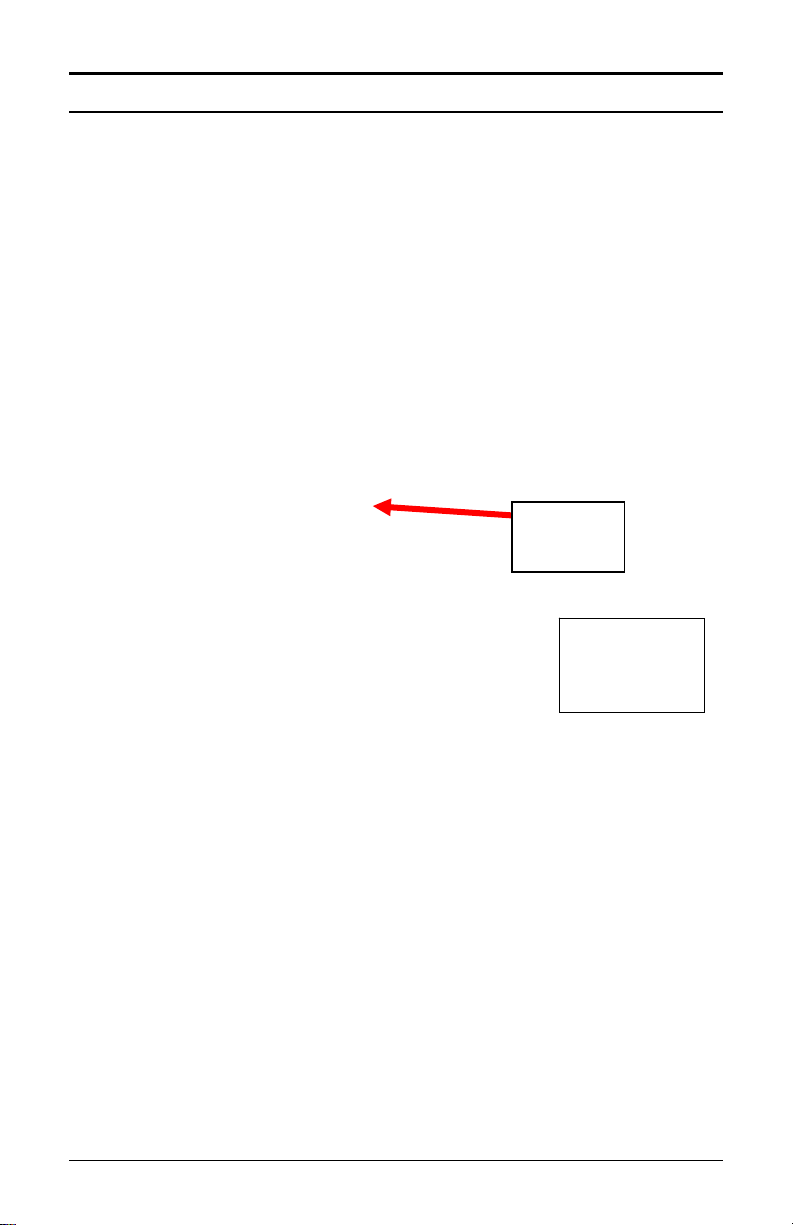
Chapter 3: MTX-15 Diagnostics
Running Diagnostics
In addition to a power up diagnostic, the MTX-15 has an internal
diagnostic utility for verifying the correct operation of the terminal,
adjusting the display contrast and configuring network communi cations
(Ethernet terminals only).
To access diagnostics:
Step 1. Cycle the AC power on the MTX-15 or press the Reset button
on the PCB (see Figure 2).
Step 2. Press the enter
appears. After the terminal initializes, the Diagnostic screen
will appear with the Relay, Keypad, LED and Buzzer test
highlighted as illustrated in Figure 52.
Figure 52: MTX-15 Main Diagnostic Screen
Note: Cycling the power and/or using the Reset button will not erase
any employee transactions at the terminal.
Use the Function keys (see Figure 50) as indicated underneath the
display to move Up
press enter
this screen, use the Back
the main display.
and Down to highlight the desired test and
on the keyboard to advance to the test screen. From
key when the Memory Bank test first
button to exit diagnostics and return to
MTX-15 installation & Operation Guide Page 3-1
Page 52

Relay, Keypad, LED and Buzzer Test
With Rely, Key, LED, Buz highlighted press enter on the
keyboard to advance to the test screen.
Figure 53: Relay, Keypad, LED & Buzzer Test Screen
Use the Function keys to move up or down to highlight the desired test
and press enter
Keypad test: Pressing any numeric key will display the number on
the Keypad test line. Pressing the esc
while pressing the enter
keys (from left to right) will display “L”,”M”,”N” and “O”, respectively.
Press the “
Relay: With this test highlighted, pressing enter
“ON” and energize the signal relay (closing the contacts). Pressi ng
enter a second time will display “OFF” and deactivate the relay.
Buzzer: With this test highlighted, pressing enter
“ON” and sound the internal buzzer for approximately one second.
Red LED: With this test highlighted, pressing enter
display “ON” and turn the red “ERROR” LED on for one second,
then deactivate the LED and display “OFF”.
Green LED: With this test highlighted, pressing enter
display “ON” and turn the green “OK” LED on for one second, then
deactivate the LED and display “OFF”.
Press the left Function key to return to the previous Diagnostic menu.
” function key twice to exit this test.
to perform that test.
key will display “C”,
key will display “E”. The function
will display
will display
will
will
Page 3-2 MTX-15 Installation & Operation Guide
Page 53

Reader Test
With Reader highlighted press enter on the keyboard to advance
to the READER TYPE test screen (see Figure 54).
This test will display the type of reader installed in the MTX-15 terminal
and indicate the functional status of the reader.
Figure 54: Reader Type Test Screen
Swipe a badge to initiate the test. If the buzzer beeps, the green LED
(OK) flashes and the display advances to the following screen, the
reader is functioning normally:
Figure 55: Reader Test Results Screen
If the red LED (ERROR) flashes and “FAIL” is displayed instead of a
number it indicates an unreadable card. A name will appear a s illustrated
in the example shown in Figure 42 if that badge has been assigned to an
employee in the Time & Attendance software.
The test can be repeated by re-swiping a card.
Press the left Function key to return to the main Diagnostic menu.
Note: When using previous versions of Amano Time & Attendance
software only 4 digits will be displayed for employee ID instead
of 12 digits.
MTX-15 installation & Operation Guide Page 3-3
Page 54

Screen Test
With Screen highlighted press enter on the keyboard to perform
the screen test. This diagnostic tests the display by turning on all the
pixels. Any spots would indicate a defective pixel.
Press the left Function key to return to the main Diagnostic menu.
Network Configuration
This selection will only function on an MTX-15 Terminal with Ethernet
and can be used to configure network communications.
From the main diagnostic screen use the down or up function keys to
highlight Network and press enter on the keyboard to advance
to the IP ADDRESS screen. “Please Wait” will momentarily be displayed
on the bottom.
Automatic IP is the default, which will obtain the settings automatically
when the terminal is connected to the network. If this is acceptable,
press the right Function
terminal. “Please Wait” and “Rebooting” will momentarily flash along the
bottom of the display while the terminal reboots. The left Function key or
esc
terminal.
To view the IP address set by the network, from the IP ADDRESS
screen highlight Specify and press enter and the following type
of screen will appear.
Page 3-4 MTX-15 Installation & Operation Guide
key will exit without saving your setting or rebooting the
Figure 56: IP ADDRESS Screen
key to save the setting and reboot the
Page 55

Copy down the Address, Subnet, and Gateway IP settings displayed in
order to configure your Time Guardian time and attendance software.
Press the left function key or esc
maintain the automatic setting.
Note: It is important to exit this screen without saving. If save is
pressed, the terminal will reboot with the displayed address in
manual mode (see below); automatic IP setting will be
disabled.
If you need to set the IP Address manually use the IP Address window.
You may need to obtain the appropriate IP settings from your network
administrator.
Enter the IP Address, Subnet Mask and Gateway settings using the
Figure 57: IP Settings Screen
key to exit the screen to
numeric keypad. The Up
to move between the three fields.
Press the right Function
automatically reboot the terminal. “Please Wait” and “Rebooting” will
flash along the bottom of the display for a few minutes while the terminal
reboots. The new settings will be in effect after the terminal reboots. The
left Function key or esc
rebooting the terminal.
and Down Function keys will allow you
key to save the settings. This will
key will exit without saving your setting or
MTX-15 installation & Operation Guide Page 3-5
Page 56

Invalid Network Settings
If you set the IP Address manually with the wrong IP Address, Subnet
Mask, and/or Gateway Address one of the following error messages may
be displayed;
ERROR Invalid IP Address,
Invalid subnet mask,
Invalid gateway address, or
Invalid network configuration (no route from host to gateway)
Press enter
You may need to obtain the appropriate IP settings from your network
administrator.
to reboot the terminal and clear the error message.
Contrast Adjustment
This function adjusts the contrast of the LCD display.
From the main diagnostic screen use the down or up function keys to
highlight Contrast and press enter on the keyboard to advance
to the Contrast adjustment screen.
Figure 58: Contrast Adjustment Screen
Use the Up and Down Function keys to darken or lighten the contrast.
Press the right Function
Diagnostic menu. Use the left Function key or esc
without saving your setting.
key to save the setting and return to the
key to exit
Page 3-6 MTX-15 Installation & Operation Guide
Page 57

Specifications
Operating Environment:
32°F to 113°F (0°C to 45°C) 10 - 90%
relative humidity, non-condensing
AC Adapter Power Input:
Power Consumption:
Dimensions:
Weight:
Daylight Saving Time
(DST):
Employee Badges:
Readers:
105 - 130 VAC, 50-60 Hz
1.5 Watts (Serial version)
2.1 Watts (Modem version)
3.0 Watts (Network version)
8.86" L X 5.5" W X 1.9" D
(225 mm L X 140 mm W X 49 mm D)
6 lbs. (2.7 kg)
Settings are programmable through
Amano Time & Attendance software.
3.375" L X 2.215" W X 0.030" D
(86 mm L X 54 mm W X 0.76 mm D)
Magnetic stripe card badges conform to
Amano proprietary standard.
Barcode badges are Amano standard
code 39.
Proximity devices have embedded chip
with Amano format.
Index No.’s A201, A202 and A203: Magstripe reader that accepts Amano
proprietary standard mag-stripe
encoding.
Index No.’s A204, A205 and A206:
Equipped with visible barcode reader
that accepts Amano standard code 39
barcode card.
Index No.’s A207, A208 and A209:
Proximity reader, ACI format
Memory Backup:
Battery Backup:
(Optional)
MTX-15 installation & Operation Guide Page 3-7
Provides up to 1 year of continuous
memory backup without AC power.
(6) AA size alkaline (non-rechargeable)
batteries.
Page 58

Battery Backup Time
(Range dependant on
reader type)
Display:
Keypad:
External Signal
Capability:
Serial Version: 14 to 24 hours
Modem Version: 7 to 10 hours
Ethernet Version: 5 to 6 hours
2.8” diagonal, 128 x 64 dots resolution
LCD reflective (no backlight)
3x4 keypad (0~9, ENT, ESC)
+ 4 function keys (used for Cost Center
/Job costing feature).
1 Dry contact: 1A, 24V, Class 2 circuit,
Normally Open
Page 3-8 MTX-15 Installation & Operation Guide
Page 59

Page 60

www.amano.com/time
AMX-407600 ● Copyright © 2010 Amano Cincinnati, Inc. ● Printed in U.S.A. ● 5/10/0
 Loading...