

Page 1
Corporation
YOKOHAMA
JAPAN
AMANO ELECTRONICS OF AMERICA, INC.
1485 N Manassero Street, Anaheim, CA. 92807.
U
NEW JERSEY OFFICE
N.J
80 Little Falls Road,
07006,US.A
LOS ANGELES OFFICE
U
3071 E. Ceena Court, Anaheim, CA 92806,
S.A.
CHICAGO OFFICE
650 Grand $304 Elmhurst,
ILL.
60126,
DALLAS OFFICE
TX.
2156 West Northwest, Highway, Suite 314, Dallas,
75220,
ATLANTA OFFICE
8601 Place, Suite 340 Atlanta, GA. 30350,
U
NE W YORK OFFICE
1180 Avenue the Americas Suite 820, New York, N. Y. 10 03 6, US.A.
TORONTO OFFICE
2740 Boulevard East, Unit Mississauga, Ontario Canada
AMANO ELECTRONICS
Westerring 2, 3600, Genk, Belgium
AMANO
ELECTRONICS EUROPE N.V. BRUSSELS OFFICE
31 Vuurberg,
EUROPE
1831, Belgium
N.V.
OFFICE &GENK
FACTORY
AMANO DEUTSCHLAND GMBH
Stadionring German.
CORPORATION
Eclipse Road, Sparta, North Carolina, 2867 5, U .S. A.
a
...
I
1900
PrintedinJapan
Page 2
Contents
INTRODUCTION
Introduction
List of EX9000 Series
Accessory
BEFORE OPERATION
PlaceofInstallation
to Remove the Front Case
ConnectionofBattery (Full Power Reserve) (option)
HowtoInstall onWall
Name a nd Function ofEach Part
InitialValue
HOWTOOPERATE
TIMECARD
ListofTypes ofTime Card
Adjustment toCard Width
Adjuslment ofSideMargin
Adjustment to Card Thickness
Adjustment of Slot Depth
SIGNAL
Connection ofTimeSignal Line
.......................................................................
..............................................................
.........................................................................
...............................................................
..............................................................
...........................................
..........................................................
....................................
..............................................................
.............................................
......................................................................
....................................................................
...........................................................................
..........................................................
..........................................................
.........................................................
......................................................
...........................................................
..........................................................................
O
OO]
..................
..............
...................................
EX9500
.........................
1
1
2
2
10
11
12
18
18
19
19
20
20
SETTING METHOD
Setting
Setting ofDate
Setting of Time
Print Column Change-overTime (In t he case of 1-row-a-daycard)
Print Column a nd
Setting of Pay Period EndingDate and Blank Row(In the case ofMonthly Pay)
Setting
Setting ofDaylight Saving Time (to month and day)
SettingofDaylightSaving Time (tomonth and day ofwhich week)
Time Signal Duration
Print Format
Settingof2-color Printing
SettingofTime Signal EX9200 and EX9500
Setting of Print Column
SettingofRESTRICTED
ExampleofMain Settings
Example ofMain Setting (CopyingofWeekly Program)
MODIFICATION
Additional Setting
MAINTENANCE
of
Modification
CancellationofSet Details
Changeof Ribbon
Under SpecificSituations
Maintenance
......................................
............................
......................................................
..........................................
.....................................................
............
Change-overTime (In the case of 2-row-a-day card)
Pay Period Ending Day o f and Current Week(In the case of Weekly Pay)
...................................
. .
......
<
.............................
..........................
.................
ZONE
................
<
EX9500
.........
.....................
............................
.................................
......
OF
SET
DETAILSOFWEEKLY PROGRAM
(or
Confirmation) ofWeekly Program
...................................
....................................
.................................................................
..........................................................
.......................................................................
..................................................................
...........................................................
................................................................
..........
.....................
...........
.............
...........
21
21
22
23
24
26
27
28
29
30
31
34
35
36
37
38
39
40
40
41
41
42
42
43
43
APPENDIX
Indexof Itemsfor Setting
Weekly Program Setting List
............................................................................
...........................................................
.......................................................
44
45
Page 3
INTRODUCTION
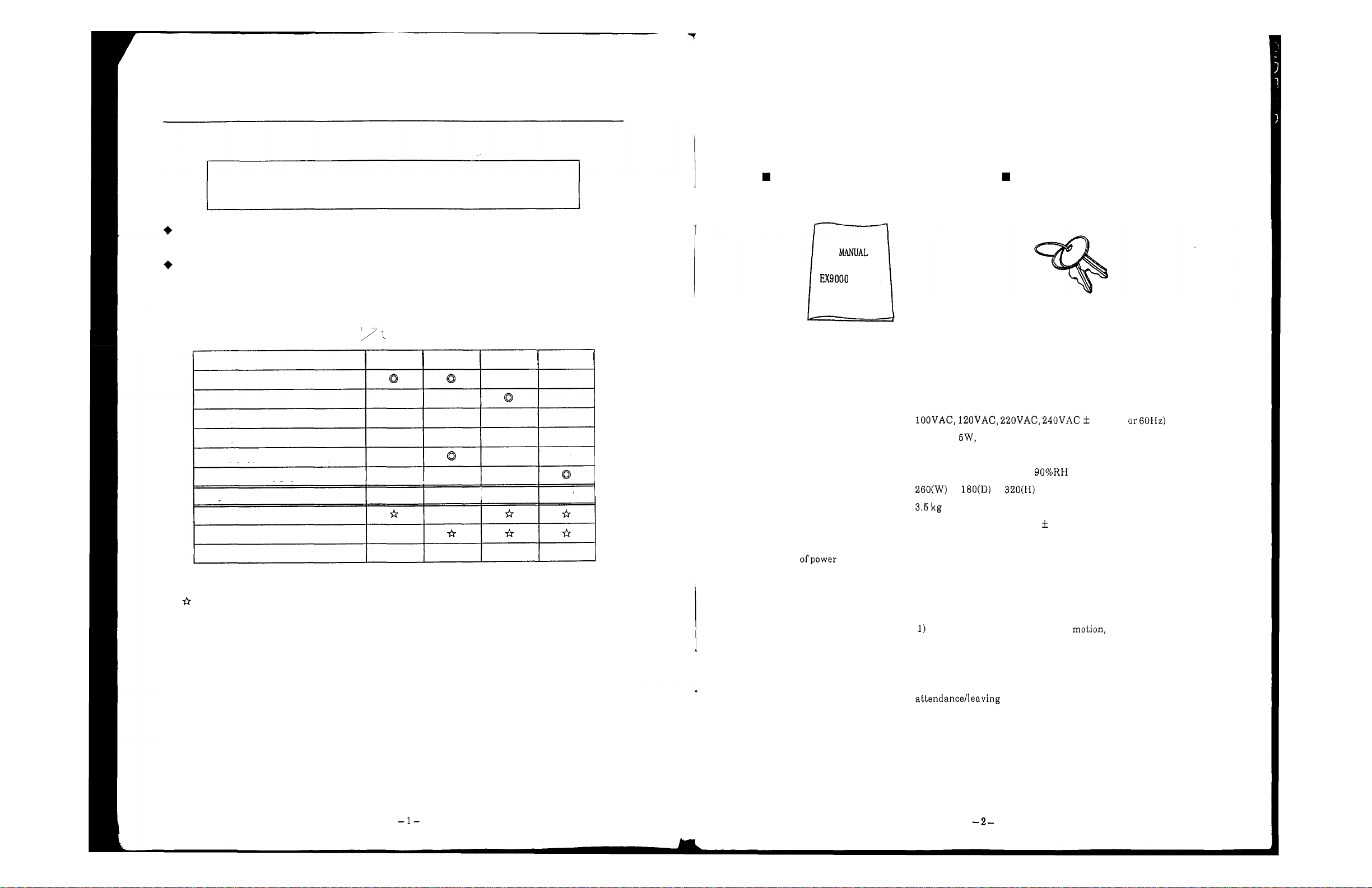
Accessory
After unpacking the package ofEX9000Series,pleasecheck all the accessories.
We hope you will read this instruction manual and operate EX9000 Series
correctly
Please note that specification, apperance, descriptions, etc. may be subject to change due to
improvementofproduct.
This manual has been prepared very carefully, but, if you find a n y errorordescriptions which you
cannot understand clearly, please contact the dealer from whom you have bought our EX9000
Series.
List of
EX9000
1-color printing
2-color printing
Timesignal
Shiftof print column
Monthly pay, vertical weekly pay
Horizontal weekly p ay
Full power reserve OP
Column dividing sensor
Party line function
Tw o time signal circuits
OP
:
Optional
:
Extension
so
Series
:
:
as
tolet them operatefullyefficiently foralong time.
EX9000 EX9050 EX9200 EX9500
Q
Q
Q
Q
Q
Q Q
I
I
OP
I
I
OP
Q
OP
*
*
*
Availableatdealersatthe time of purchase.
Since expansion functions ar e assembled i n during pr o d uc tion process in our
us
plant, please inform
is
somethimes impos sible to assemble the expansion function in your unit
toreplace your unit afterpurchase.
in advance that you need the expansion functions. It
*
*
*
or
Instruction Manual Key
OPERATION
SERIES
Production Specification
Power source
Power consumption
Environmental conditions
Outside dimensions
Weight
Clock system
Power compensation at
the time
failure
:
:
Ordinary Maximum 30W
:
Temperature
Humidity
:
:
:
Crystal oscillator, Accuracy 3 seconds (20°Cto30°C)aweek
:
For3years of accumulated power failure time with lithium baltery
(All functionsother than the inner clock sto p.).
Full power reserve
When t he battery is fully charged, the followings are c om pe ns ated:
2) 200times of printing, but within
When the unit
X
For less than72hoursofclock 2-color selection, shift
print column, time signalormelody.
:
:
X
is
10%(50
-
10°Cto 45°C
10%
to
operating on the full power reserve, the
lamp goes on andoff.
(withoutdew condensation)
72
hours.
of
Page 4
BEFORE
OPERATION
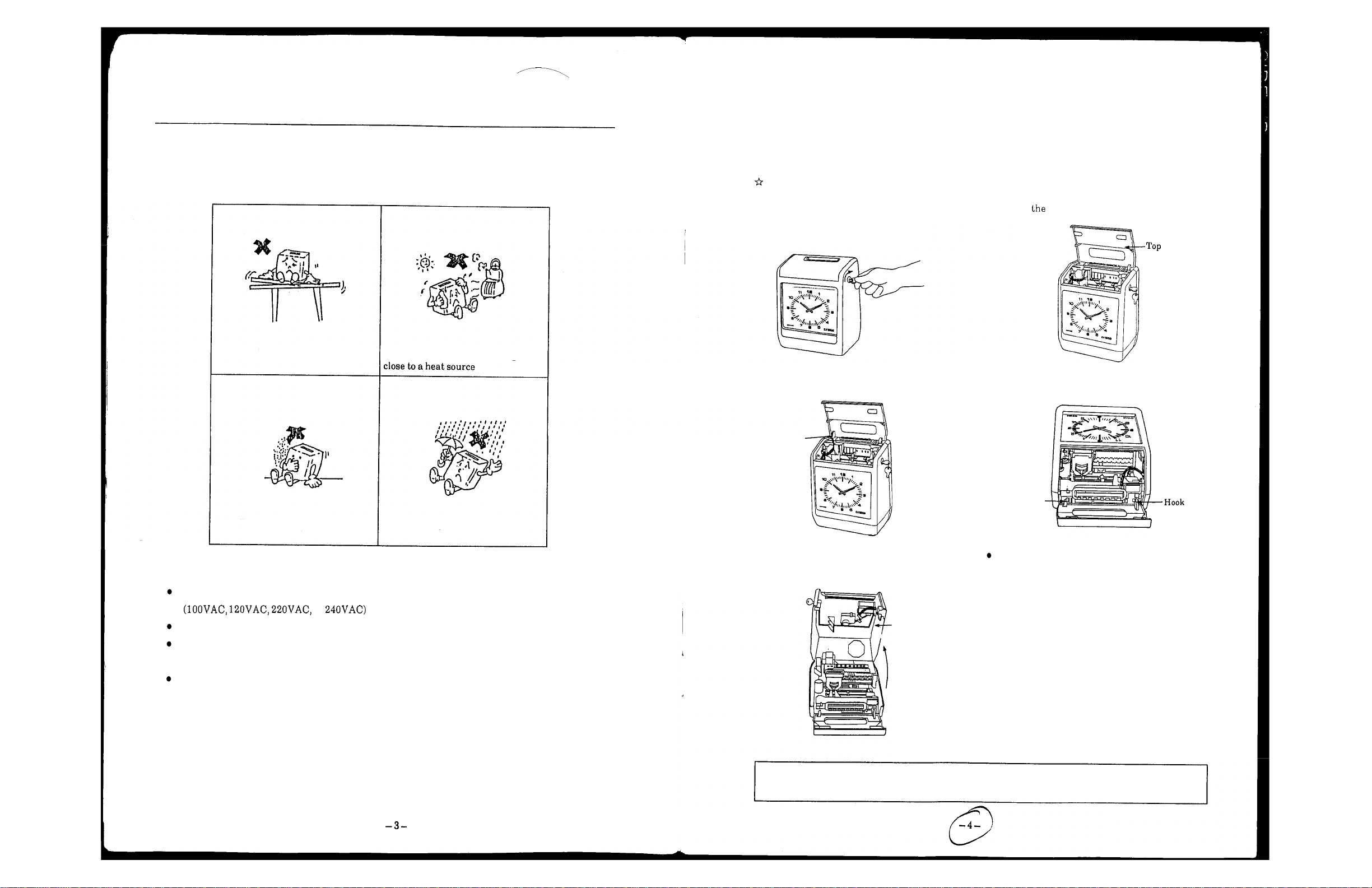
Ho wto Remove the Front Case
PlaceofInstallation
To
usethe unit f oralong ti me, donot install itat the places mentioned below:
Unstable places
Places exposed to directsunlightor
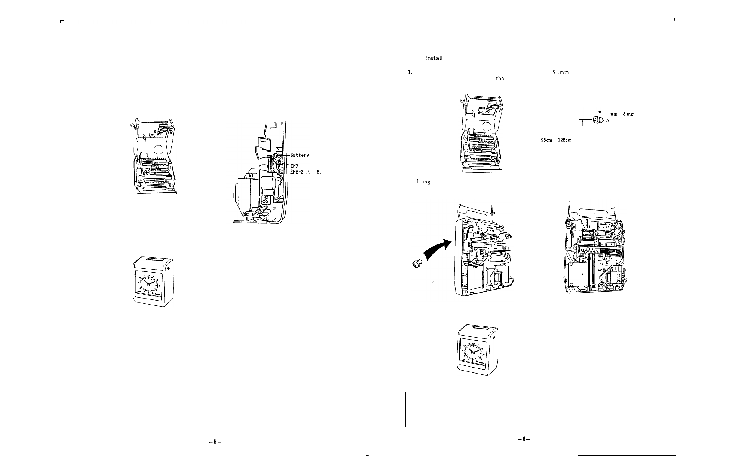
The front cover shou ld be re moved when setting the battery (full power reserve), connecting the time
a
signal cord an d w he n hanging the unit o n
Before removing the front case, besure topull off thepower cable from the plug receptacle.
1.
Turntheke y to thearrow direction. 2. Open top cover.
3.
Remove the c on ne ct or as shown below:
Connector
wall.
cover
4. Face the backplate o fthe unit to the ground.
Dustyorvibrant places
Places exposed to rainwater
Power Source
Check the ACpower commercially available in your district.
or
Select such places where supplyvoltages a re stable.
Make the power available all the day from the power source, which sh ou ld be independent from
other equipment.
The unit containsa lithium battery inside, and the inner clock keeps running.
(For3years ofaccumulated powerfailuretime.)
Hook
5.
Widen th e upper right and left hooks by force
and liftthe front case toremove i t .
Front
case
I
Whenremoving the front case, be sure toface th e backplate ofthe unit to the ground (unless hung on
a
wall). When the front case is removed without turning it aside, the rear case may fall down.
Before closing the front case, connect the
connec to r removed i n the Procedure
3.
Page 5
1
ConnectionofBattery
1.
Pull off the power cable from th e plug
(Full
Power Reserve) (Option)
2.
Insertabattery connector i n place.
receptacle, face th e backplate to the ground, Make sure tha t the inserting direction i s
then removethe connector a n d t h e front case correct.
from t h e unit.
3.
Set the front case tothe unit, insert th e
connector in the unit, then close the top
cover.
connector
C.
How
to
Pull off the power cable from t he p lug
receptacle, face the backplate to
then remove t h e connector and the front case 4mm
on
Wall
2.
Fix
a
wood screw at the
"A"
ground, shown below on the wall and leaveaspace of
or
5mm between th e wall and th e screw
from the unit. head.
4
to
to
high
from
the
floor
3.
the unit on the wood screwsothat the
Fix the unit with wood wcrews at three more
4.
wood screw enters the pobellied hole on t he pl aces.
back ofthe unit.
position
In addition to t he battery, a lithium battery is also included in th e unit, and the inner clock keeps
running.
Therefore, when you insert the power ca bl e in the plu g receptacle after connection of the battery, the
unit keeps running.
[Note]
Usecare toinsert the battery connector tothe correctdirection. If it i s inserted to th e other
dir e c t io n ,the unit may getouto forder.
5.
Set the front case to t he unit, insert the
connector in the unit and close the top cover.
Precaution concerning Installing Method an d Wall Material
When the unit
is
installed onawall madeofsoft material like gypsum board, plywood, etc., the
wood screw will become loose and the unit may drop from the wall during operation.
plate between cleats, and fix the unit on the plate. (Prepare a n appropriate plate before
installation.)
So,
set a
Page 6
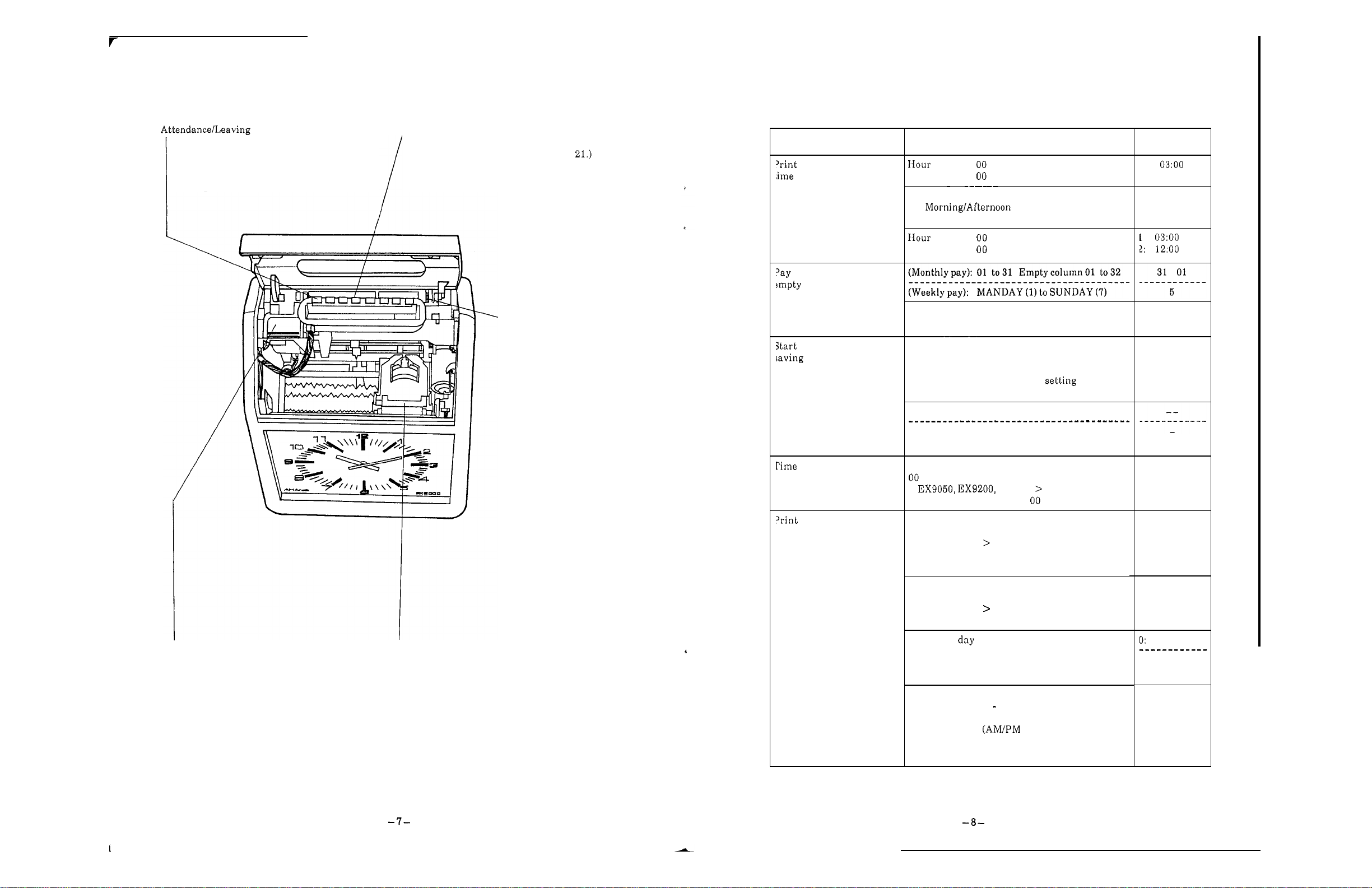
Nameand Function
of
Each
Part
(item) button
:
This button is generally used for printing in
the lightedprint column.
When the top cover is open (in the setting
mode), setting can be corresponded to t he
setting index.
Setting index
:
is used at the time of setting and t urns
around
as
the dial is rotated.
(See
Page
InitialValue
column change-over
period endingdate,
column
Items
Minute
1:
Date change-over
2:
(2
-
column-a-daycard)
Minute
Set points
:
to23
:
to59
Initial values
1
change-over
:
to23
:
to59
'Dial
:
is used to turn
the setting i nd ex.
(End) of daylight
time
signal duration
format
-
Current week: 1, 2 Bi
weekly pay is only
set.
Change-over method
O:
Nofunction
1:
Forsetting month a nd
date.
2: For month and
dayof the week
Month:O1to
12,
Day:O1to 3 1
Week:1to5Day of the week: Monday to Sunday
To
set d ay of which week
To
decidelime signal duration in sec onds:
to 59 (sec.)
<
No
time signal is output fo r (sec.)
EX9500
Manual selectionofprint column
<
EX9500 (Vertical monthly pay and vertical
weekly pay only)
O:
Manual selectionpossible
1:Manual selecl i on i mp o ss i bl e
Double stampingprevention
<EX9500 (Vertical monthly payand vertical
weekly pay only)
O:Ineffective
1
:
Effective
1
O
05
O
O
Display
:
displaysa n item selected bythe item button.
Ribbon holder
Press the holder a t the time
:
of
replacing a
ribbon, and t h e rear section goes up and the
ribbon ca n be removed.
Printingof of the
O
:
Date
3
:
French 4:German
6
:
Japanese
1
7
Printing of time
1:
24 hours(O23hours)
(O
is not printed at the ten's place ofhour.)
2: 12 hours
3:
24 hours
(O
(Oisprinted a t the ten's place of hour.)
week
:
English 2:Spanish
5
:
Italian
8
:
:
Day No.
No printing
hours)
-
23 hours)
Monthly pay
1: Weeklypay
1
Page 7
HOW
TO
OPERATE
format
Neekly
Items
2
-
printing
I
Time signal
Print column
II
Restricted
zone
color
Se t points
Printing of minute
1:
Minutes
hour
2:
3:
4:
1/10 hour
To
decide detailsforeach print color
R
Start of printing i n red
B
:
Start of printing i n black
To
decidetime signal circuit
O
:
No
:
Time signal isgiven toCircuit
2:
Time signal isgiven toCircuit 2
(extension).
3:
Timesignal i s given to Circuits1and
(extension).
To
decide print column.
(Vertical monthly pay and vertical
weekly pay only)
to The
00:
No
To decide the time zone for double stamping
prevention.
<EX9500
weekly pay only)
(Vertical monthlypayand vertical
01: Startingtime ofdoublestamping
prevention
02:
Finishing time of double stamping
prevention
A
hour
B
EX9500
EX9500
time signal i s given.
MAX
column ofeach card type.
printcolumnisshifted.
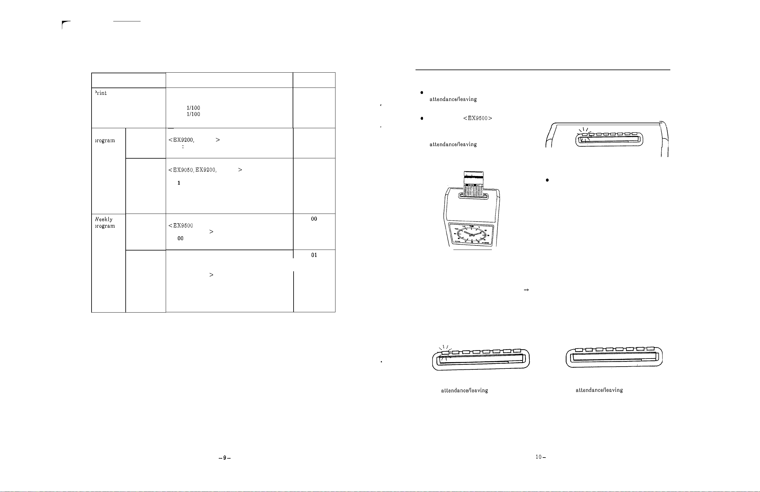
1.
Initial values
1
R
1
2
I
I
Selectaprint columnwith the
button, insertacard, and
i t is possible to print in the c o lumnwhere the
button is lit.
In the case of
columnsca n be shifted,print columns ar e
shiftedastimepasses. (Whenanother
column
replaced by t h e originalcolumn after
printing or after ten seconds.)
During Power Failure
Whenpower s upply i s suspended, everything except the inner clock s tops. When th e power supply i s
restored, everything returns to normal.
accumulated power failure time.
(When
years.)
At t he time of power failure
If
is
selected with the
a
full power reserve [Option] comes no t to function, the duration is counted i n the three
a
full power reserve functions,
for which print
button, thecolumn
is
II
Since card i s automatically pulled i n, do not
push it inor donot pull it out.
The lithium battery is effective f or three years of
If a full power reserve does not function,
The
Full Power Reserve
can compensate clock motion, 2
72
hours, or
200
timesof printing within72hours (whenfully charged).
lamp goes on and off.
The
-
color selection, shiftofprint column, time signal or melody fo r
lampgoes
-
out.
Page 8
TIME
Time
Card
CARD
List
of
TypesofTime
Card type code
Card type
Card
1
7
liftsacross t h e card
2
3
In the case
of
EX9000
series, card format can be changed by setting the inner dip switch.
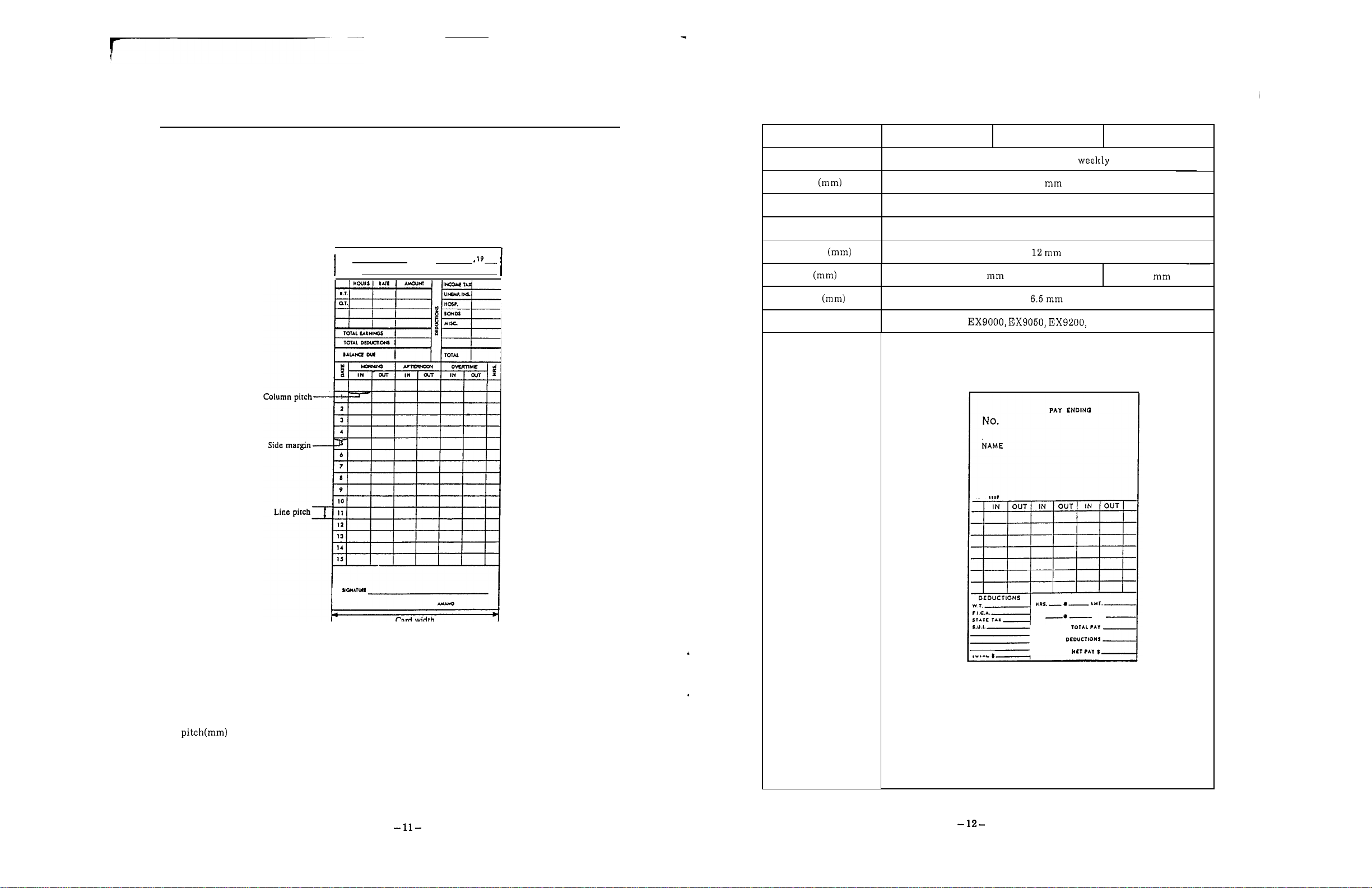
Representative timecards a r e shownasfollows.
I
Na
NAME
PAY
ENDING
+
Cardwidth
Number of columns
Numberoflines
86
6
columns
7
lifts
Column pitch
Line pitch
6
7
Sidemargin
Applicable models
EX9500
Sample
I...
To
change timecard format, inform the dealer from whon y ouhave bought
For
adjustmentofcard width, sidemargin, thickness and slot depth, see Pages
Step can be adjusted by replacing sensor belt .
Othersa r e setbydip switch.
our
time recorder.
12
to
TOTAL
TOTAL
17.
Page 9

type code
type
width
?umberofcolumns
of
pitch
pitch
margin
models
iample
(1st
6
columns
14
lifts
12
6
(2nd week)
Card type code
Card type
6
Monthlypay,
16/16
Amanostandard card
lifts , 2 sides
I
7
Monthly pay,
1
sides
15/16
lifts,
82.5
Cardwidth
4
I
columns
7
2
lifts
Number
Number
of
columns
of
lines
6
columns
16
lifts
3
2 columns
12
Colum n pitch (mm)
12
Line pitch
16
Side margin
7
(Back)
7
(Right)
EX9500
Applicable models
Sample
II
IN
OUT
IS
OUT
IN
OUT
Page 10

type code
type
8
Monthl y p a y , 31 lifts
9
TAB
card 16 lifts
the card, weekly
Card t ype code
Card type
TAB
card 22 lifts
weekly
10
the card,
16lifts the
card,weekly card,weekly
22lifts
the
width
Yumber
Yumber
Line pitch
Side margin
of
of
pitch
columns
lines
models
104
6 columns
31 lifts
12
8
Card width
7
columns
16 lifts
I
I
10.55
6
4
Number
Number
Line p itch
Side margin
Applicable models
Sample
of
columns
of
lines
pitch
7
22lifts
10.55
4.35
4
98 to 106
columns
16 lifts 22 lifts
12
6
7
-
Page 11

Adjustment to Card Width
type code
Zard type
Zard width
Number of columns
Number of lines
Column pitch
Line
margin
Applicable models
13
16
liftsdowdup the card, monthly
98
16
lifts
8
(Front)/
8
(Back)
to
8
columns
EX9500
OUT
I
TO
14
22
liftsdowdup the card, monthl y
106
22
lifts
10.7
4.35
7
-
TO
7 (Back)
1.
Pull off the power cable from plug receptacle,
Loosen three screws indicated in the figure
face th e backplate of the unit to the ground with a Phillips type screwdriver and adjust
and remove the connectorand thefront case.
the slot width to t he one of card to be used.
The width can be adjusted i n the range from
82.5
106
mm.
Screw
AdjustmentofSide Margin
1.
P u l l off t h e power cable from t h e p lu g
receptacle, face the backplate of th e unit to section indicated by hand
th e ground a n d remove t h e connector an d the i t with
front case.
After having removed the case, hold th e
2.
a
Phillips type screwdriver and adjust
the side margin. (Scalesa r e indicated.)
The adjusting range extends from 3mm to
mm.
below, loosen
15
-
Page 12

AdjustmenttoCard Thickness
TIM
/
E
-
'SIGNAL
Pull off the power cable from t he plug
1.
receptacle, face the backplate of the unit to right and left dials
the ground an d remove th e connector an d t he forth width
front case.
2. After having removed t he case, l ur n both
The adjusting range extends from
to
0.9
mm.
At th e time of shipment, this width is set to
0.37
mm.
Dial
AdjustmentofSlotDepth
to
adjust the back and,
of
th e slop. (Scales a r e indicated.)
ConnectionofTime Signal Line
1.
Pull off the power cable from th e plug
receptacle, face the backplate of the unit to case left bot to m.
the ground and remove th e connector and the
front case.
3.
Press the protrusion on the top of th e time
siganal terminal and insert the time signal connector and close th e topo cover.
lines in
t he cord h older. In the cases of time signal
second circuit and parental function
(expanded functions), insert them i n
and
Nos.
1
and3.Then, fix them with
Nos.
5.
2.
Pass
the time signal line through t he rear
4.
Set the front case to unit, insert the
4
2.
Pull of t he power cord from the plug
1.
receptacle, face t h e backplate of the unit to section indicated in the figure with
th e ground an d remove t h e connector and the type screwdriver and adjust the depth.
front case. (Scales are indicaled.)
After having removed th e case, loosen th e
a
The adjusting range extends from 17mm to
Phillips
Screw
I
Time Signal Line
WiringDiagram o fTime Signal Line
Time
signal
unit
a
Include
noise absorbing capacitor example,S-1205) in t h e time signal unit,
Bell
or
buzzer
Cord holder
Specification for
Time circuit
1
Contact capacily
inductive load max.
Contact output
No-voltage contact output
:
circuitsc an be expanded.)
:
inductive load max.
:
Page 13

SETTING METHOD
SettingofDate
Setting
O
For program setting,open the top cover, and the setting mode starts. Turn the setting index, press
the item button, then start each setting.
all
O
hours on t h e millitary hours system.
Set
CLOCK
HWMN
START
DAY
HWMN
DAY PRINTINO RESTRICTED
D.L.S.
END DURATION
WEEKLY PROGRAM1
WEEKLY
POSITION ZONE
IMPRINT
MELODY DAYON DAYOFF
II
CURRENTW.
BLANK
C
t
I
t
I
t
t
DAYON DAYOFF
E
E
E
-
-
E
Example:Set"August the time recorder.
1.
Press the button, and the present dateisindicated.
CLOCK
HWMN
2.
Set"91"tothe year usina the
to 90representthose
of
20009,
CURRENTW.
BLANK
+
or
-
button.
whi l e91 to 9 9 representthose of
1900s.
3.
Press the Ebutton.
4.
Set to the month by using the
5.
Press the Ebutton.
+
or
-
button.
t
E
I
on
the
display
turnstogoing
on
effective.
When a n item is changed to another during setting, items registered by button ar e effective.
(Weekly programs ar e excluded.)
Starts and ends of Daylight Saving Time and Restricted Zone should be s e t together at the same
Also,
time.
such setting may not extend beyond the print column changeover time.
6.
Set tothedaybyusing t he
7.
Press theEbutton.
+
or
-
button.
Page 14

SettingofTime
Example
1.
Set a.m."onthe recorder.
:
Press the but t on . and the time is indicated.
Print Column Change-overTime (Inthe
:
Example
I
1.
Set the print column change-over time to
Pressthe
DAY
CHANGE
button,and the initial value appears.
caseof1-row-a-day card)
LI
CLOCK
2.
Set
"08"
to
the hour b y using the+or-button.
:
Note
3.
PresstheEbutton.
Sethours ont he millitary hours system.
4. Set"48"tothe minute by using th e+or-button.
5.
Press theEbutton.
CURRENT
BLANK
+
E
I
T he clock startsrunning immediately after the button hasbee n
pressed.
*
When the clock is slightly fast, press the STOP button.
The clock stops while the button is pressed a n d starts runningimmediately after thebuttonhas been
released
CLOCK
HWMN
2.
Set
"04"
tothe hour by using the +or-button.
3.
PresstheEbutton.
4.
Set"30"tothe minute b yusing the+or-button.
5.
PresstheEbutton.
J
BLANK
+
E
-
Page 15

PrintColumn and Change-overTime
(Inth e
Example
case
of 2-row-a-day card)
:
Set the change-over time to
1.
Press the DAY CHANGE button, and the initial values appear.
1
:
Division1(Datechange-over time) 0 3
2:Division 2 change-over time) 12
CLOCK
2. Set"2"tothe divisionby using the +and-buttons.
:
CURRENTW.
t
:
Pay
Setting of
Example:Set pay period endingdate to the 25thday of a month and a blank rowa t the 17th row.
E
2.
"25"
Set
Period Ending Date and Blank
CLOCK
HWMN
lo the pa y period endingdateby using the+and
CURRENTW.
Row
(Inthe
-
case
of
Monthly
Pay)
3.
Pressthe E button.
(The initial value forthe Division 2 appears.)
4. Set"14"tothe hour byusing the+and-buttons.
5.
Press the E button.
"30"
6. Set
7. Press the Ebutton.
to the
using the +and-buttons.
Press E button, and the blank row turns to
3.
"
17.
"
I
4. S et t he blank row by using the
Press the E button.
5.
Blank Row
The top row
row on theback isnumbered 32,and
setby designating a number onthe card.
*
When
25th day, th e blank row automatically turns to
Whenapay peri od ending date isset to anyother date,
the initial value
of
time card is numberO1an d th e lowest
a
pay period ending date is set to the 20th or
"1"
remains unchanged.
+
and-buttons.
a
black row can be
Front of card
(Top row)
Toprow
Second row
16th row
(Bottom row)
Back ofcard
1
I
2nd
9th
17th 18th
25th 26th
-
to
leave this column of the card blank.
8th-Front side
16th Backside
24th Front ride of the card
32nd Backside
1st
card
(Top row)
17th row
181hrow
32th row
(Bottom row)
Page 16

Setting
(Inthe
of
case
Pay
Period Ending Da yofthe Week and Current Week
of
Weekly Pay)
of
Setting
DaylightSaving Time (to month an dday)
Example:Set the starting date ofdaylight saving time toJuly
5.
Example:Se t the pa y period ending day ofthe we ek to Saturday (bi-weekly pay) and the current week
to t h e second week.
1.
Pressthe CURRENT PAY END BLANK button, and the initial
values appear. (The payperiod ending dayof the week is Friday,
andthe current week is the first o ne .)
CLOCK
2.
Set
"2"
tothe current week by using t he+and-buttons.
*
Only bi-weekly pa yisset.
3.
Pressthe E button.
4.
Set
"6"
to the day of the week by using+and-buttons.
:
Monday:Tuesday:Wednesday:Thursday
:
Friday
:
Saturday:Sunday
CURRENTW.
BLANK
t
E
1.
Press the D.L.S. START button, and the initial value appears.
D.L.S.
START END
2.
Select
+
3.
PresstheEbutton.
4.
Set
D.L.S.
"1"
as t he setting methodof daylight svaing time by usin g the
IMPRINT
and-buttons.
"07"
tothe month by using+and-buttons.
E
O
:
No
function
1
:
Settingofmonth and date
2
:
Setting of month and day of the we e k
I
I,,
5.
Press"E"button.
*
When the card specificationis set toweek pay, the current week is not shown on the display.
5.
Pressthe E button.
6.
Set
"05"
to
the da y by using the+and-buttons.
I
\
I
LI
PresstheEbutton.
8.
Also, set the ending date of daylight saving time in the same wa y.
Se t both the stating and ending datesofdaylight saving time. When only either of themisset,
is
daylight saving time
When the starting date and the endingdatear e set to
Thechange
-
over time fordaylight saving time is a.m.
notset.
a
same date,the both dates ar e erased.
I
Page 17

I
SettingofDaylightSavingTime (to month an ddayofwhich week)
Example Set starting dateofdaylight saving to t he second Monday ofJuly
1.
Pressthe
D.L.S. D.L.S.
START END
2.
Select"2"as thesetting method o fdaylight svaing time by usingt he
+
3.
Pressthe button.
4.
Set to th emonth by using+and-buttons.
D.L.S.
and-buttons.
STA RT button, and the initial value appears.
DURATION
IMPRINT
+
Settingofmonth and date
1
:
Setting of month
2
:
E
day of the week
SettingofTime Signal Duration
Example
1.
*
:
Set the time signaldurationto10seconds.
Press the SIGNALDURATION button, and the initial value
appears (for
D.L.S.
START
Set
"10"
(Thesetting range extendsfrom
outputa t
PresstheE button.
Even in the case of 2-circuit output of time signal [Extension], t h e time signal duration is set lothe
same
5
seconds).
D.L.S.
END DURATION
tothe time signal duration by using the+and-buttons.
second.)
IMPRINT
to59seconds.Notime signal is
+
E
I
,
I
5.
PresstheEbutton.
6.
Set"02"toth e week by using
and-buttons.
1:1 st week 4:4th week
2: 2nd week
3:
3rd week
7.
Press lhe Ebutton.
8.
Set"1"tothe day ofthe by using+and-buttons.
:
Monday
:
9. PresstheE butto n.
10. Also, set the ending date o fdaylight savingtime i n the same wa y .
Set
both the stating and ending datesofdaylight saving time. When only either of them is set,
daylight saving time
When the startingdate and the ending date ar e set to
The change
-
overtimefor daylight saving time
5:
Tuesday
:
Saturday
is
5t h week
not set.
+
: :
Sunday
is
Thursday
In
a
same date,the bothdates a re erased.
a.m.
I
Page 18

SettingofPrint Format
Example: Set the print column manual selection to possible, t h e double printing prevention to
12
effective, indication of d ay of the week to English, hour indication to th e
hou r s)and minute ind icalion to the
Printcolummanual (applicable to vertical
1: Manual selection possible
Double printing prevention weekly
O:
Ineffective 1: Effective
Indic at io n ofd ay of t h e week Print format
O:
Date
3:
French
6:
Japanese7:Day
Minute indication
1: Minutes
3:
Printcolumn manual seleclion
By use of"print column shifting",aprinting column other than the preset column may be selected
manually.
Double printingprevenlion
Sometimes is difficult to identify work beginning time work ending time. Toprevent double
printing, print column should be changed over from t he work beginning time to work ending time.
Otherwise, nothing is printed even if
*
Be cautious that setting t heprinling column manual selection to impossibleand
prevention to effective will make the unit unprintable during working hours.
*
In the case of
weekly pay ar e set),start setting from Procedure
1: English
4:
German5:Italian
B
No.
2:
8:
Spanish
No
indication
2:
4:
EX9200
2:
Manual selec tion imp ossible
1:
24
hours
(O
is not printed a t the ten's place ofhour.)
2:
12 hours hours)
3: 24
hours
(O
is printed a t the ten's placeofhour.)
A
a
cardisinserted.
and
EX9500
(when horizontal monthly pay and horizontal
6
below:
(O
(O
monthly pay and vertical
-
23
hours)
-
23
hours)
hours
double printing
2.
Set the"printcolumn manual seleclion"by use
3.
PressEbutton.
4.
Set
"1"
to th e double printingprevention by using the+and
buttons.
5.
Press theEbutton.
Set
but tons.
<The following proced ur es are applic ab le to all models.
7.
Press the Ebutton.
8.
Set
9.
Press the
EX9500
"1"
tothe indication of d ayof th e weekby using
"2"
t o the print format by using th e+and-buttons.
E
of
+
and-buttons.
the
and
-
-
I
I
I
I]
1.
Pressthe IMPRINT button, and valueappears.
D.L.S.
START
END
DURATION
E
When the card typei s weekly pay, the
initial value
is
10.
Set
"3"
to minute indicalion by using th e and-buttons.
11. Press the E button.
Page 19

hour A, hour B an d 1/10 hour
:
Settingof2-color Printing
Minute
hour
11100hour
1/10hour
1/10hour
15
15
-
-
A
02
05 05
05
10 10 10
Example:Start 2-color printing a t a.m.from Monday to Friday.
1.
Select WEEKLY PROGRAMIfro mthe setting i n de x e s ,and
program No.appears.
a
I
90
90 95
WEEKLY
DAY
2. Press the DAY button.
3.Ada y of th e week is set asfollows:
:
Monday:Tuesday:Wednesday:Thursday
:
Friday Saturday:Sunday
When setting
press the DAY ON button. In the othercases, press t he DAY
button.
4.
To
set the time when 2-color printingstarts,follow the procedures
mentioned i n the Paragraph
a
da y oft h e week wherethe LED goes on and off,
I
"
CLOCK
C
Page23.
+
E
OFF
5.
Press th eWEEKLY PROGRAMIand the buttons.
:
Start ofprinting in red
R
B
Start of printing in black
Use the
press the E button.
6.
Checkifthe above settingiscorrect, and press theEbutton againto
register the setting.
(Thenext program
+
and-buttons to indicate on the dis pla y, then
No.
is indicated.)
Page 20

Setting
of
Time
Signai
EX9200
and
EX9500
Setting
of
Print
Column
Example
1.
:
a
timesothatatime signal goesona t from Monday toSaturday.
Select WEEKLY PRO GRAMIfrom the setting i n de x e s ,and a
program No. appears.
WEEKLY PROGRAM
DAY
HWMN
2.
PresstheDAY button.
3.
A d ay of the week i s set asfollows:
:
Monday:Tuesday:Wednesday:Thursday
:
Friday
When setting
:
a
day of th e week where the LEDgoes onand off,
I
SIGNAL
Saturday:Sunday
C
t
DAYON
press the D A YONbutton. In the other cases, press the DA Y
button.
4.
Tosetthe time when the time signal goes on,follow the pr ocedures
mentionedin the Paragraph
"
SettingofTime"Page
23.
I
DAYOFF
OFF
E
I I
Example
1.
Shiftt he printcolumn to the Column 4at f ro m MondaytoSunday.
Select WEEKLY PROGRAMIIfromthe setting indexes, anda
programNo. appears.
WEEKLY
DAY PRINTING
HWHM POSITION ZONE
Pressthe DAY button.
2.
A day of t he week is set
3.
:
Monday:Tuesday:Wednesday:Thursday
:
Friday
II
RESTRICTED DAYON
as
follows:
Saturday:Sunday
t
When setting a day o f the weekwhere the LEDgoeson and off,
press the DAY
ON
button. In the other cases,press the DAY
button.
Tosetthe lime whe naprint column is shifted, follow the procedures
4.
mentioned i n t he Paragraph
"
SettingofTime"Page
23.
DAYOFF
OFF
E
El ElElEl
5.
Press theWEEKLY PROGRAMIand t h e SIGNALbuttons.
O:
Nosignal goes on.
1
:
2
:
3
:
Use the
The signal goeson in Circuit
The signal goeson in Circuit [Extension]
The signal goeson i n both Circuits1and2.[Extension]
+
and-buttons to d e cide the content to be indicatedonthe
1.
display, then press the E button.
6.
Checkif the above settingis correct, a n d press theE button again to
register the setting.
(Thenextprogram No.is indicated.)
Press the WEEKLY PROGRAM
5.
to
buttons
display.
Use t he
set the position ofthe column to be shiftedtoon the
to t h e MAX column ofeach card type)
+
and-buttons to position the print column,then press
II
and the PRINTINGPOSITION
the E button. If the print col umnshiftingis set to
before printing and after printing stays
programming.
Checkif
above settingiscorrect, a n d press t heEbutton again to
register th e setting.
(Thenext program No.
is
indicated.)
the column
without regard tothe
Page 21

of
Setting
RESTRICTEDZONE
EX9500(Vertical monthly payandvertical weekly pay)
ExampleofMainSettings
:
Example
Start printing in blac k and sound a time signal at Monday to Saturday.
Example
Make the Double Printing Prevention effective between and from Monday to
:
Friday.
Select WEEKLY PROGRAMIIfrom th e setting indexes, and
program
DAY
2.
Press the DAY button.
A d a y of the week is set asfollows:
3.
When setting
press the D A YON bu tt on .
No.
appears.
WEEKLY
PROGRAM
POSITION
:
Monday:Tuesday
:
Friday
:
Saturday:Sunday
a
day ofth e week where t he LED goes on and off,
II
RESTRICTED
ZONE
:
Wednesday:Thursday
In
the other cases, press the DAY O F F
DAYON
button.
Tosetthe time zone during which
4.
double stampingprevention
remainseffective, follow the procedures mentioned i n the
Paragraph
5.
Pressthe WEEKLY PROGRAMIIand t h e RESTRICTEDZONE
"
Settingof Time"Page
23.
buttons.
O1
:
Start of double stampingprevention
02
:
En d ofdouble stampingprevention
Use the
+
and-buttons toindicateO1or02on t h e display a nd
press the E button.
1.
Select the WEEKLY PROGRAMI,seta day ofthe week and a time,
E
thence press the
button.
a
WEEKLY
PROQRAM
I
DAY
+
DAYOFF
E
2.
Press the button, indicate "B"on the displayby using
the
+
and-buttons, then press the E button.
3.
Pres the SIGNALbutton, indicate
SIGNAL
"1"
C
on th e display by using the
+
DAYON
DAYOFF
+
E
I
and-buttons, thence press theEbutton.
4.
Checkif the above setting a r ecorrect,and press the E button again
to register the setting.
(The next program
Ifthe E button iskept bein g p res se d for
For the details, seePage
*
If you have madeamistake during the settingprocedu r e s , press the C button. The function of the
No.
38.
appears.)
2
secondsat this stage, the weekly program is copied.
C
button depends on the length of the time that the Cbutton is kept beingpressed.
When the Cbutton has been pressed for less than
2
seconds,P-O5appearson the display (and
program remain).
2
When the Cbutton has been pressed for more than
seconds, th e contents of relevant program
a r e completelyerased.
6.
Checkifthe above setting is correct, an d press the E button again to
register the setting.
(Thenext program No . is in dicated.)
Register the ending time
7.
of double stampingprevention i n
the same w ay.
*
Be sure to set the starting and ending times of double stamping prevention together at the same
time. These times cannot bese t when extending beyond a printcolumnchange
-
overtime.
Page 22

ExampleofMainSetting (Copying ofWeekly Program)
MODIFICATION OF SET DETAILS
OF
WEEKLY
PROGRAM
Copyi ng of Weekly Program:
Details (day
of
the week and set in aprogram ar e copied in its ne xt-numbered program. When
the next programs have already been set, however, they are copied in the smallest-numbered
program not set.
Example:Sound time signals at
Setaweekly programtosoundatime signal a t
WEEKLY PROGRAM
WEEKLY
PROGRAM
DAY
HWMN
SIGNAL
2. Keep pressing the E button
9:00
and fr om Monday to Friday.
9:00
in the
I.
C
for
2 seconds, andanumber ofprogram,
t
DAYON
DAYOFF
E
in whic h th e weekly program iscopied, appears on the display.
No.
7
(to
is empty.)
and press th e
E
(WhenProgram
3.
Release theEbutton. Then,you will s et th e time.
4.
Change the time
Modification (or Confirmation) of Weekly Program
Example:When modifying (confirming) 2-color printing and time signal,
1.
Open the top cover and select the
setting indexes.
WEEKLY
PROGRAM
I
DAY SIGNAL
HWMN
2.
Selectaprogram
No.
to be modified
C
(or
confirmed) by usingthe
and-buttons.
Example
3.
PresstheEbutton, and the detailsofthe program to b e (or
:
Program
No.
12
confirmed) appear on the display.
Thedetails mean tochangeover
to
printing in bl ac k andlosound
time signal a t from Monday toFriday.
4.
When modifying th e press the button o fan itemtobe
+
modified, modify it by using th e
and-buttons, thenpress the
button toregister.
:
Modify
so
as
to
Example
sound a time signal a t
change over to printing i n black and to
from Monday to Friday.
I
among
t
DAYON DAYOFF
a
E
I
E
I
5.
Sel the lime signal in the same wayasthat mentioned in Paragraph
"
Setting ofTime Signal"Page then press th eEbutton.
6.
Checkif the setting is correct, then press theE button again
register the setting.
(Thenext program number appears.)
to
After completionofmodification, press the
5.
No.
program
modified in the Procedure
program
(Press
appears on the display. When nothing ha s been
4,
press t he+button, and the next
No.
appearsonthe display.
the-button toindicate the previous program
E
button, and the next
No.)
Page 23

Add
i
ti
o
naISetting
1.
Open the topcover a nd select th e WEEKLY PROGRAMIamong
settingindexes.
MAIN
ChangeofRibbon
NCE
WEEKLY
DAY SIGNAL
2.
Keep pressing E button for2seconds,a nd an empty program
No.
appears on l hedisplay.
3.
Toset an additional item, see the WEEKLY PROGRAM from Page
I
C
t
DAYON
34.
CancellationofSet
1.
Open the topcover a n d s el ec t t he WEEKLY PROGRAMIamong
Details
settingindexes.
WEEKLY
PROGRAM
DAY REDlBLACK SIGNAL
HWMN
I
C
+
DAYON
DAYOFF
DAYOFF
I
E
E
Open the topcover,thedotprinter head moves
2.
tothe plac e where yo u can change the ribbon. a t the end
3.
Setanew ribbon cassette correctly between
th e ribbon guideand the dot printer head.
Ribbon
4.
Turn the knob clockwise, and the ribbon
becomes light.
guide
To
remov e the ribbon, pul l t he ribbon holder
of
the ribbon to you, and t h e ribbon
So,
end comes out.
pull it off.
I
I
Ribbon
I
holder
2.
Selectthe program
No.
tob e canceled by using the +and
buttons. (Programs can be canceledeven after having dis pla yedthe
contents by pressing the
:
Example
3.
PresstheC button for2seconds
CancelProgram
time.), a nd you will hear
E
button.)
No.
"
Pip!
3.
(All
items go on and offduring the
"
Now,
th e cancellation ha s ended.
-41-
-
Dot
printer
5.
Close the top cover.
-42-
Page 24

Under SpecificSituations
APPENDIX
When the error sound goes"Pip, pip, and the lamp goes out,atrouble h as
occurred inside the unit. Pull out an d disconne ct the powe r cord plugjustfor once, before inserting back
to
the receptacle after a little while. In case the unit would not restore the normal state, contact the
dealer from whomyou have bought the unit.
Under the condition, t h e clock st ops, and n o time card cannot bestamped.
Errorcode
Errorof analog clock
Columnhome po siti on error
Column timing pulse error
.
Abnormal setdetails of weekly
program
Dai
I
y
Maintenance
Cleaning of case when it becomes dirty:
Meaning of error
Measures
the dealer fromwhomyou have
bought the unit.
Set th e weekly program again.
Ifit cannot be restored, contact the dealer
fromwhomyou have bought the unit.
Wetasof t clo th with water orneutral detergent and
wipe t he case lightly with the close. Daylight saving time (todate)
D onot use benzine, (volatile) thinner and other
chemical for cleaning, but the case may be deformed
or discolored.
Do not spray insecticide over the case, but the case
may also be deformed or discolored.
Index of Items
When settingaprogram, open the top coverand the setting mode appears. Turn the setting index
select items and press items buttons forsetting.
Set al l hours an d minutes on the millitary hours system
Itemsforsetting and their explanations are
Date
Time
Printcolumn change
(1
-
row-a-day card)
Print column change
(2
-
row-a-daycard)
Pa y period ending date, blank row
(monthlypay)
Pa y period ending day of t he week,
currentweek (weekly pay)
Daylight saving time
(tomonth and day o fwhich week)
Time signal duration
Print format
Weekly
program
program
for
Setting
Items
-
over
-
over time,
change-over time
I
Timesignal
II
RESTRICTEDZONE
as
follows:
Explanation
Toset year, month and day.
Toset hour an d minute.
Toset the time forchanging overprint column.
To
set the time forchanging overprintcolumn
and also the time forchanging over morning and
afternoon.
Toset pay period ending dateand blank rowin
time card.
To
setpay period endingday of week a n d
current week (in the case ofbi
To setdaylight saving time toa designated date.
Tosetdaylight saving time to
month and dayofwhich week.
To
set the length o ftime signal.
Tosetformatsfor da ily printing
(day ofthe week, 12
hours system and minute indication system)
Tosetitemschangedover to 2
Tosetdetails forsounding time signal.
To
set
column
To
set the time zone of double stamping
prevention.
-
hour systemormillitary
No.
for shifting column.
-
weekly pay card).
a
designated
-
color printing.
lo
Page
22
23
24
25
26
27
28
29
30
31
34
35
36
37
Wipe th e window glass with a drysoft cloth. Note that the is seciallv finished.
Page 25

Weekly Program Setting
Example ofEntry
PROGRAM
NO.
DAY
SettingList
I
DAY
MO TU WE SA S U
08
13
15
16
MO TU WE SA
MOTU
WE TI1 SA S U
MOTUWETHFRSASU
MOTUWETHFRSASU
MOTUWETIIFRSASU
MOTUWETHFRSASU
MOTUWETHFRSASU
MOTUWETHFRSASU
List
SU
SIGNAL
I
PRINTING POSITION
I
I
I
I
I
I
I
I
RESTRICTED
I
I
I
I
02
I
02
I
I
I
O1
I
I
I
02
02
02
02
02
02
02
02
02
02
02
02
02
02
02
02
02
02
02
02
I
I
WEEKLY PROGRAM
WEEKLY PROGRAM
:
:
I I
RIB
I I
I
I
RIB
R
I
SIGNAL PRINTING POSITION
1
SIGNAL PRINTING POSITION RESTRICTED
B
WEEKLY PROGRAM II
RESTRICTED
WEEKLY PROGRAM
I
I
II
I
02
02
02
02
I
02
I
02
I
02
02
I
02
02
02
PROGRAM
NO.
26
27
28
29
30
31
32
33
34
35
36
37
38
39
40
41
42
43
44
45
46
47
48
49
DAY
MOTUWETHFRSASU
MOTU WE SA
MOTUWETHFRSASU
MO TU WE
MO TU WE
MO TU WE SAS U
MOTUWETHFRSASU
MOTUWETHFRSASU
MO
TU
WE FRSA SU
MO TU WE
MO TU WE FRSA SU
MOTUWETHFRSASU
MOTUWETHFRSASU
MO TU WE
MOTUWETHFRSASU
MO TU WE
MO TU WE FRSA SU
MO TU WE
MOT U W E FRSA
MO TU WE SA
MO TU WE FRSA SU
MO TU WE
MO TU WE FRSA SU
MOTUWE
SA SU
SA
SA
SASU
SA
FRSA
FRSA
SU
SU
SU
SU
SU
SU
SU
SU
DAY
:
:
:
:
:
:
:
:
:
WEEKLY
PF
BLACK
RIB
RIB
I
I
RIB
I
50
50
weekly programs can be setatmost.
*
2-color
*
RESTRICTED
I
MO TU WE
:
02
MOTUWETHFRSASU
printing
R
B
ZONE
O1
02
:
Starting time for changing over to printing in red
Time
for
changing over to printing in blac k
Start of double stamping prevention
Endofdouble stamping prevention
02
 Loading...