

Page 1

CP-5000
Electronic Time Recorder
User’s Guide
Page 2

Proprietary Notice
This document contains proprietary information and such information
may not be reproduced in whole or part without the written permission
from Amano Cincinnati, Inc. 140 Harrison Ave., Roseland, New Jersey
07068.
Amano Cincinnati, Inc. reserves the right to make equipment changes
and improvements which may not be reflected in this document. Portions
of this document may have been updated to include the latest hardware
or firmware version, if applicable.
To ensure safe use of this time recorder/stamp, be sure to thoroughly
read this manual in its entirety before any attempt is made to operate the
equipment. After you have finished reading this manual, be sure to store
it and in a safe place for further reference.
Thank You…
For purchasing another fine product from
Amano Cincinnati, Inc.
Page 3

Table of Contents
Chapter 1: Introduction..........................................................................1-1
Specifications.......................................................................................1-1
Accessories..........................................................................................1-2
Names and Functions of Parts.............................................................1-3
Front Panel Description........................................................................1-3
Chapter 2: Getting Started.....................................................................2-1
Top Cover ............................................................................................2-1
Front Cover..........................................................................................2-2
Removal............................................................................................2-2
Installation.........................................................................................2-2
Placement/Location..............................................................................2-3
Desktop Installation...........................................................................2-3
Wall Mounting....................................................................................2-4
External Signal Connections................................................................2-6
Optional Accessory Battery Pack (ATR-20095x)..................................2-8
Installation.........................................................................................2-8
Power Connection................................................................................2-9
Initialization and Reset.........................................................................2-10
Reset Button......................................................................................2-10
Initialization (All Clear).......................................................................2-10
Chapter 3: Time Cards ...........................................................................3-1
Making a Test Print ..............................................................................3-1
Chapter 4: Programming .......................................................................4-1
Introduction ..........................................................................................4-1
General Programming Guidelines........................................................4-1
Entering Program Mode ....................................................................4-1
Entering and Saving Values..............................................................4-2
Scrolling Through the Program Mode................................................4-2
Exiting Program Mode.......................................................................4-2
Programming Guide
Basic Programming..............................................................................4-6
Programming Password (Menu 3).....................................................4-6
Year, Month, and Date (Menu 1, Items 1 & 2)...................................4-6
Hours and Minutes (Menu 1, Item 3).................................................4-8
Daylight Savings Time (DST) (Menu 2)................................................4-9
Automatic Adjustment Settings..........................................................4-9
Programming DST (Menu 2, Items 1 – 3) ..........................................4-10
Disabling DST ...................................................................................4-11
Hours Display and Imprint (Menu 4, Items 1 – 7).................................4-12
Index Number Imprint (Menu 4, Item 8)................................................4-14
Signal Duration (Menu 5, Item 1) .........................................................4-14
Weekly Programming (Items 01 – 80)..................................................4-15
Functions Available in Weekly Programming ....................................4-15
Creating a Weekly Program ..............................................................4-16
..........................................................................4-3
CP-5000 User’s Guide i
Page 4

Obtaining a Printout of Programmed Data (Menu 7).............................4-18
Editing Weekly Programs .....................................................................4-19
Adding Additional Weekly Programs.....................................................4-19
Deleting a Weekly Program..................................................................4-20
Chapter 5: Maintenance..........................................................................5-1
Service..................................................................................................5-1
Exterior.................................................................................................5-1
Ribbon Replacement............................................................................5-1
Time/Date Memory Backup Battery......................................................5-3
Chapter 6: Troubleshooting...................................................................6-1
Introduction...........................................................................................6-1
General Problems.................................................................................6-1
Signal.................................................................................................6-1
Foreign Object or Material .................................................................6-2
Programming.....................................................................................6-2
Key Failure.........................................................................................6-2
Audible Beeps....................................................................................6-2
Error Messages ....................................................................................6-3
Err 1 thru Err 9...................................................................................6-3
Display Related Problems ....................................................................6-7
Low Battery........................................................................................6-7
Power Failure.....................................................................................6-7
Inaccurate Clock................................................................................6-7
LED’s Not Functioning..........................................................................6-7
Hour Change ........................................................................................6-8
Card Feed Problems.............................................................................6-8
Card Refused.....................................................................................6-8
Card Cannot Enter or Card Blocked ..................................................6-8
Card Refused, Date and Time in Display...........................................6-9
Imprint Problems...................................................................................6-9
Overprint
............................................................................................6-9
Imprint Position Wrong.......................................................................6-9
Wrong Color Printed ..........................................................................6-10
Weak or Light Printing .......................................................................6-10
Diagnostics (Menu 8)............................................................................6-11
LED Test (Menu 8, Item 1).................................................................6-11
Mode and Keys Test (Menu 8, Item 2)...............................................6-12
LCD Test (Menu 8, Item 3) ................................................................6-13
EPROM (Memory) Test (Menu 8, Item 4)..........................................6-13
Buzzer Test (Menu 8, Item 5) ...........................................................6-14
Signal Test (Menu 8, Item 6)..............................................................6-15
Motor Test (Menu 8, Item 7) ..............................................................6-15
Firmware Version Number (Menu 8, Item 8)......................................6-16
Print Counter (Menu 8, Item 9) ..........................................................6-16
Card Print Test (Menu 8, Item 10) .....................................................6-16
Chapter 7: Appendix...............................................................................7-1
ii CP-5000 User’s Guide
Page 5

Chapter 1: Introduction
Before attempting to use the Amano CP-5000 time recorder/stamp,
please carefully review Chapter 1: “Introduction”, Chapter 2: “Getting
Started”, Chapter 3: “Time Cards”, and Chapter 4: “Programming”. This
chapter of the manual covers the specifications, accessories, names and
functions of parts, LCD Display, and description of controls.
Specifications
Power Requirements:
Power Consumption: 6 W Idle, 60W maximum
Ambient Temperature: 32°F to 113°F (0°C to 45°C)
Ambient Humidity: 10% to 90% (non-condensing)
Dimensions: 12.3” (313 mm) High X 10.2" (259 mm) Wide X 6.1" (155 mm)
Weight: Approximately 9.00 lbs. (4.1 kg)
Environment: Indoor use only; dust-free environment. Keep out of direct
Mounting:
Time Card: Amano Time Cards
Ribbon: Two-color cartridge
120 VAC ± 10%, 50/60 Hz
Deep.
sunlight.
Wall or Table Mount
Amano Part Number: C-3000 Time Cards
3.36 ± .016” (85.4 ±.4mm) (W) x 8.27” (210mm) (H) 150 lb.
Manila card (.0126” (0.32mm) thick)
Amano Part Number: CE-316452
CP-5000 User’s Guide 1-1
Page 6
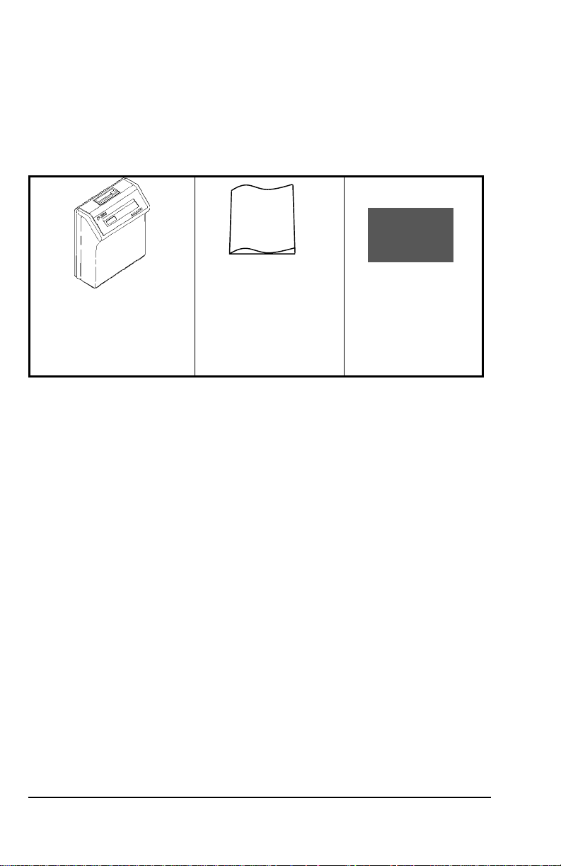
Accessories
The following accessories are provided with the Amano CP-5000. After
unpacking, please ensure that all of the following items are provided:
User’s
Guide
CP-5000
This User’s Guide
(1 unit)
(1 copy)
(one pair, 2 keys)
Keys
• Please note that specifications, appearance, and/or description are
subject to change without notice due to product enhancements.
• This user’s guide has been carefully prepared, but Amano assumes
no liability for errors and/or omissions. If you should find any errors
or unclear information, please contact your Amano dealer.
1-2 CP-5000 User’s Guide
Page 7
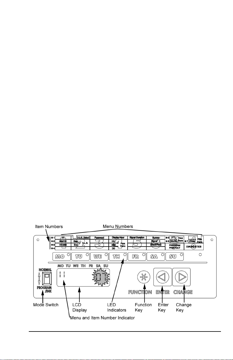
Names and Functions of Parts
The following describes the names and functions of various parts of the
CP-5000.
External View
Front Panel Description
The front panel displays the date, time, day of the week, and is used for
programming the unit. It is accessed by removing the top cover. (see
Chapter 2: “Getting Started” for more details).
CP-5000 User’s Guide 1-3
Page 8
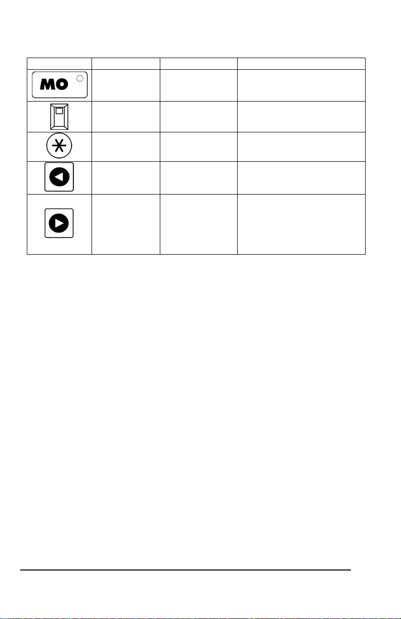
Component Name Normal Mode Program/Ink Mode
LED Indicator Day of the week Current menu in display
Mode Switch Normal Operation Enter Program/Ink Ribbon
Function Key Not Available Move to the next menu
Enter Key Not Available Accept data in the display, and
Change Key Not Available Edit data in the display. Pressing
replacement mode
move to the next item in the
current menu or next menu.
this key will increment the
displayed value by one. Holding
the key down for more than three
seconds will increment the
displayed value by ten.
Note: ESD (Electrostatic Discharge) precautions should be observed
before removing the top cover.
1-4 CP-5000 User’s Guide
Page 9
Chapter 2: Getting Started
Before using the Amano CP-5000 time recorder/stamp, please carefully
review this chapter of the manual, which covers:
• Top cover removal and installation
• Front cover removal and installation
• Placement/Location
• Desktop Installation
• Wall Mounting
• External Signal Connections
• Battery Connection
• Initialization and Reset
• Power Connection
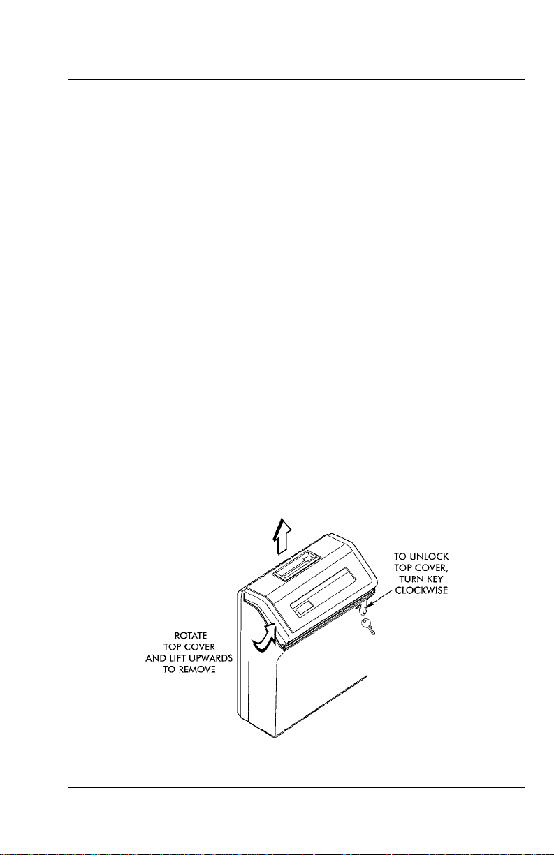
Top Cover
The top cover must be removed to configure, install, and program the
CP-5000. To remove the top cover, follow these steps:
1. Insert the key provided in the keyhole, and turn the key clockwise to
unlock the cover. The top cover should “pop” open.
2. Pivot the top cover upwards, and lift the cover to remove.
3. To re-install the top cover, set and align it with the groves on the
housing, then press it into place until it clicks.
CP-5000 User’s Guide 2-1
Page 10
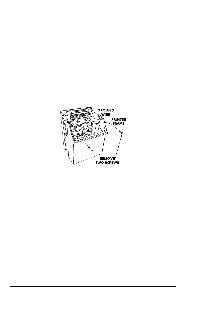
Front Cover
Removal
The front cover must be removed to connect the Full Power Reserve
Battery and connect the external signal line for the CP-5000. To do so,
perform the following steps:
1. Disconnect the power cord from the power source if applicable.
2. Remove the top cover.
3. Lay the unit face up on a flat surface.
4. Facing the front of the unit, remove the two Phillips head screws in
the upper corners of the housing.
5. Press both of your hands flat against the sides of the front cover.
6. Pivot the front cover towards you. Support the front cover so that it
doesn’t stress the ground wire connections. Set face up on a flat
surface.
Installation
1. With the front cover on a flat surface and facing up, press both of
your hands flat against the sides.
2. Facing the bottom of the unit, set and align the tabs on the bottom of
the front cover with the grooves on the housing.
3. Pivot the front cover towards the housing. Reconnect the ground
wire, push the cover down in place and secure it with the two Phillips
head screws.
4. Reinstall the top cover. Reconnect the power cord to the power
source.
2-2 CP-5000 User’s Guide
Page 11
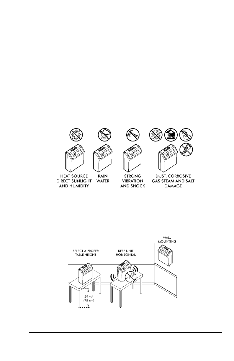
Placement/Location
When choosing a mounting location for your CP-5000, you should
ensure the following parameters are met:
• The mounting surface and hardware is capable of supporting the
unit’s weight, approximately 10 lbs., or 4.54 kg.
• The area must be within the specified operating temperature range
(see page 1-1).
• The unit has access to a power source (AC wall outlet).
• The area can accommodate signal and/or power conduits.
• The following conditions do not exist:
Desktop Installation
Place the time recorder on a level surface. The recommended height of
the surface should be 29½” (75 cm) from the floor.
CP-5000 User’s Guide 2-3
Page 12
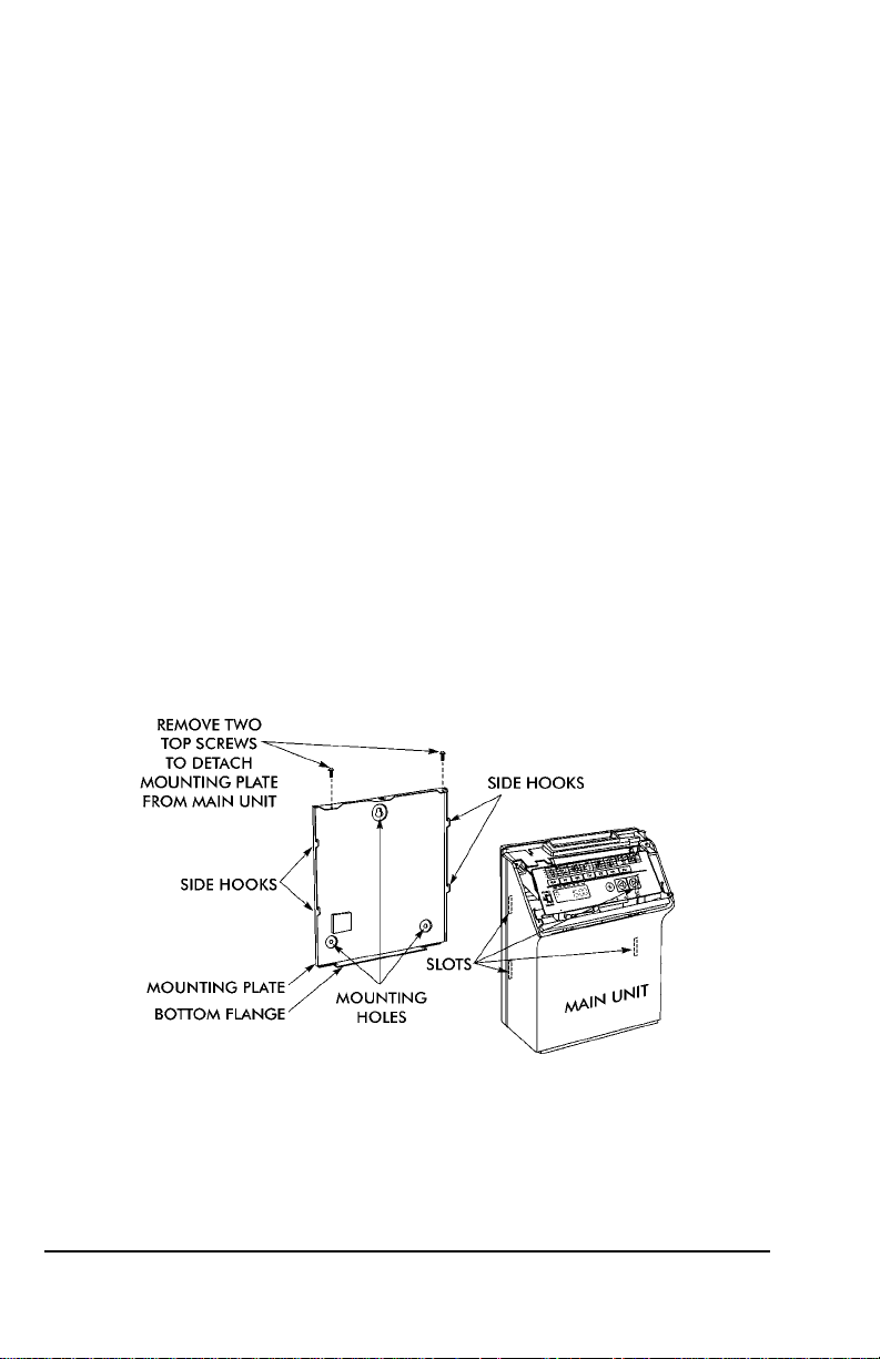
Wall Mounting
For proper wall mounting, follow these steps:
1. Disconnect the power cord from the power source.
2. Unlock and remove the top cover.
3. Remove the two screws on the top and slide the back plate
downward to remove it. Set the CP-5000 face up on a flat surface.
Note: The right side back plate screw also secures a ground wire.
4. Using a punch, knock out the center material from the teardropshaped mounting hole on the back plate.
5. Using the back plate as a template, approximate the final location of
the clock, and mark the location of the teardrop mounting hole on the
wall.
6. Hang the back plate on a screw or anchor from the teardrop-shape d
mounting hole.
7. Level the back plate and mark the location of the bottom two
mounting holes.
8. Secure the back plate to the wall by inserting screws through the
bottom two mounting holes.
9. Holding the sides of the cover, lift the CP-5000, bottom forward, to
the back plate.
10. Align the tabs on the bottom of the CP-5000 housing with the
grooves in the bottom flange of the back plate. Hold the CP-5000 in
place so that the tabs are even with the bottom flange. Do not rest
the unit on the flange.
2-4 CP-5000 User’s Guide
Page 13
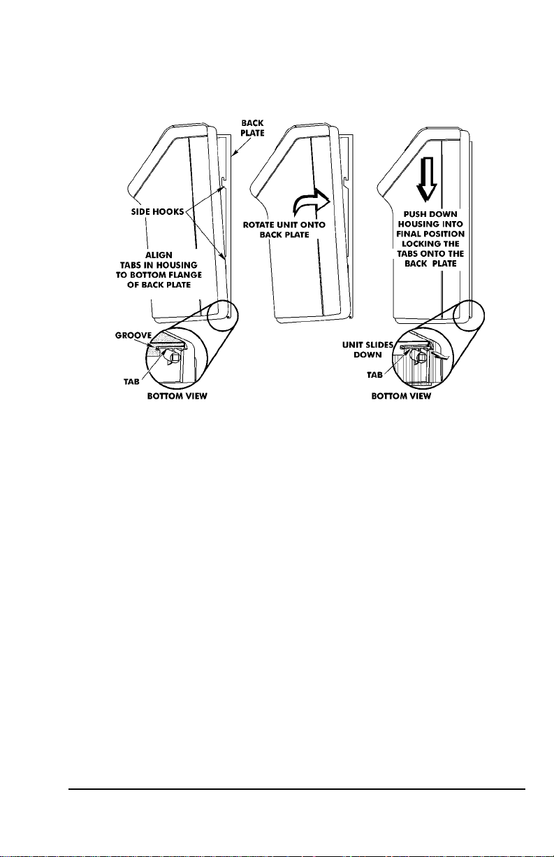
11. Carefully pivot the CP-5000 away from you onto the back plate until
its side hooks fit in the slots on the back of the unit. The upper flange
of the back plate should be aligned with the slot in the top of housing.
12. Install the two screws that secure the back plate to the unit. Make
sure you re-install the ground wire.
13. If you need to connect external signal wiring, or connect the battery,
do not replace the top cover or reconnect the power cord at this time.
CP-5000 User’s Guide 2-5
Page 14

External Signal Connections
The CP-5000 is equipped with a single external signal relay circuit that
enables you to activate an audible device such as a bell or buzzer. The
relay contacts of the circuit are Normally Open and should not exceed
Class 2 Circuit requirements (24 VDC at 1A). The duration (in seco nds)
that the relay contacts will be activated or closed is set in the Signal
Duration menu item, and the time of the day and day of the week that
this will occur on is set in the Weekly Programming menu.
The wiring schematic for the external signal relay circuit is as follows:
Note: This procedure must be performed with power to both the
external device and the CP-5000 disconnected.
To connect a device to the relay signal circuit, perform the following
steps:
1. Make sure that power to both the external device and the CP-5000
are disconnected.
2. Following the manufacturer’s guidelines for the external device,
connect the signal wires to it and run them to the mounting location
of the CP-5000. Make sure the wires are properly labeled.
2-6 CP-5000 User’s Guide
Page 15
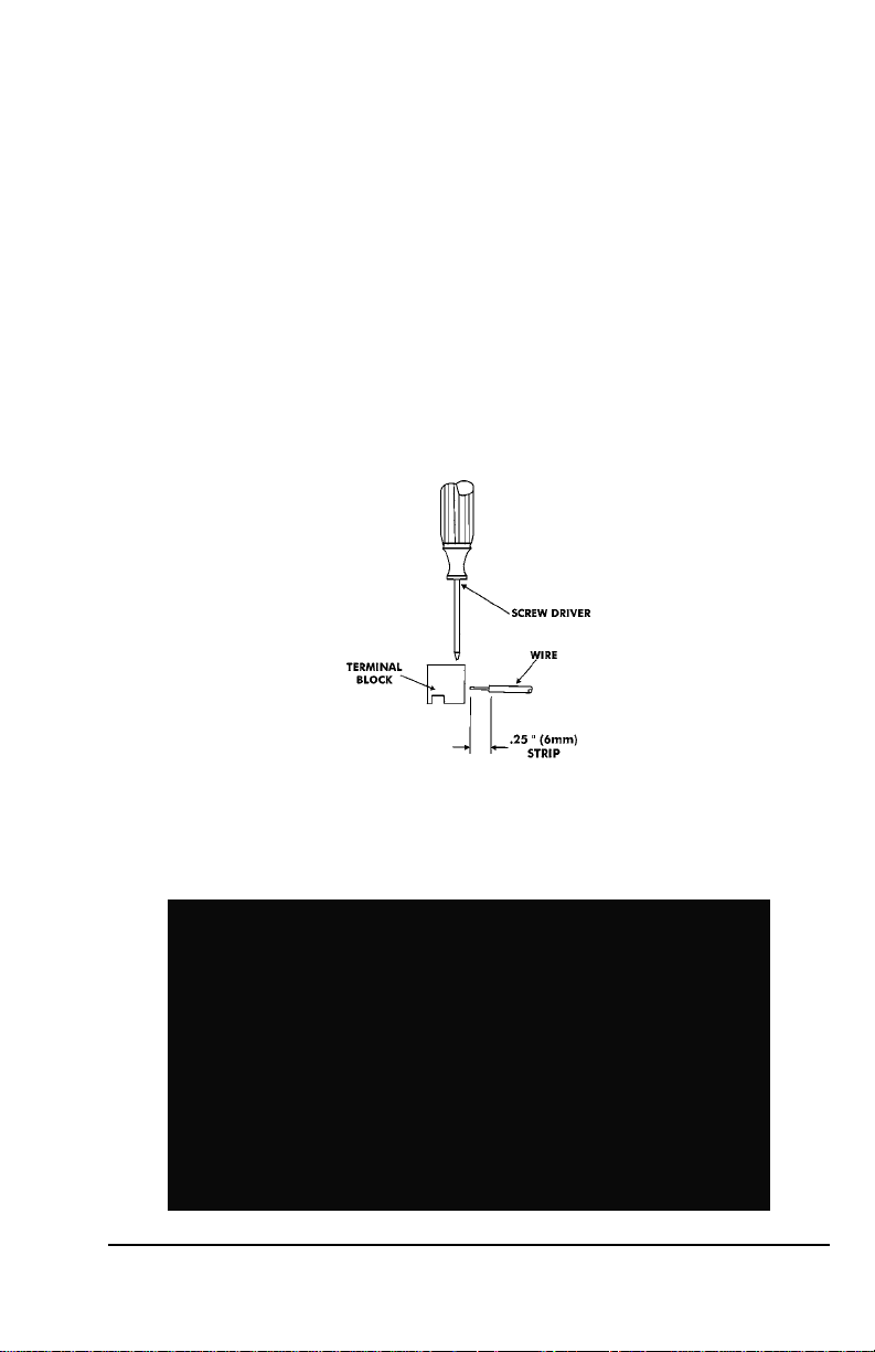
3. Strip approximately .25” (6 mm) of insulation off the ends of the wires
that will be connected to the CP-5000.
4. Remove the top cover from the CP-5000.
5. Remove the front cover; support the cover so that it doesn’t hang
from the ground wire.
6. With the unit flat and face up, locate terminal block TB1.
7. Using a small-blade screwdriver, loosen the screws on the TB1 side
of the connector block.
8. Observing polarity, insert one wire into the CP-5000 through the
open hole and connect it to the proper terminal position of TB1.
Using a screwdriver, secure the wire in place. Insert the other wire
into the unit and secure in place. Make sure that only the stripped
wire is clamped, and not the insulation.
9. Check the connections by tugging on each wire. If they appear loose,
repeat the previous step.
10. Clamp the signal wires as shown in the following drawing using a
cable clamp appropriate to your cable thickness.
CP-5000 User’s Guide 2-7
Page 16

Optional Accessory Battery Pack (ATR-20095x)
Installing the Full Power Reserve Battery (available as a kit: P/N ATR20095x) will allow the CP-5000 to maintain normal operations for 12
hours or 300 punches in the event of an AC power failure.
Installation
Note: This procedure must be performed with the power cord
disconnected from the power source.
To install the Full Power Reserve Battery perform the following steps:
1. Remove the top cover.
2. Remove the front cover.
3. Remove the back plate.
4. Remove the backing paper from the Velcro.
5. Slide the battery pack into the compartment and press firmly into
place to allow the adhesive on the Velcro fastener to hold.
6. Feed the battery cable through the cable feed slot at the top of the
battery compartment and over the top of the PC board.
7. Connect the battery cable to FPR on the PC Board.
2-8 CP-5000 User’s Guide
Page 17
Note: The battery will not power the clock until after the clock is initially
plugged in. Afterwards, power will automatically be supplied by
the battery in the event of an AC power failure.
8. Replace the back plate
9. Replace the front cover.
10. Replace the top cover.
Note: To insure premium performance it is recommended that the
battery be fully charged prior to use (approximately 24 hours).
Note: To avoid damaging the battery, or draining it to an unrecoverable
level, keep the machine plugged into an AC power source during
normal operation. The power reserve battery is intended to be
used for limited power outages, not as a power source during
normal operations.
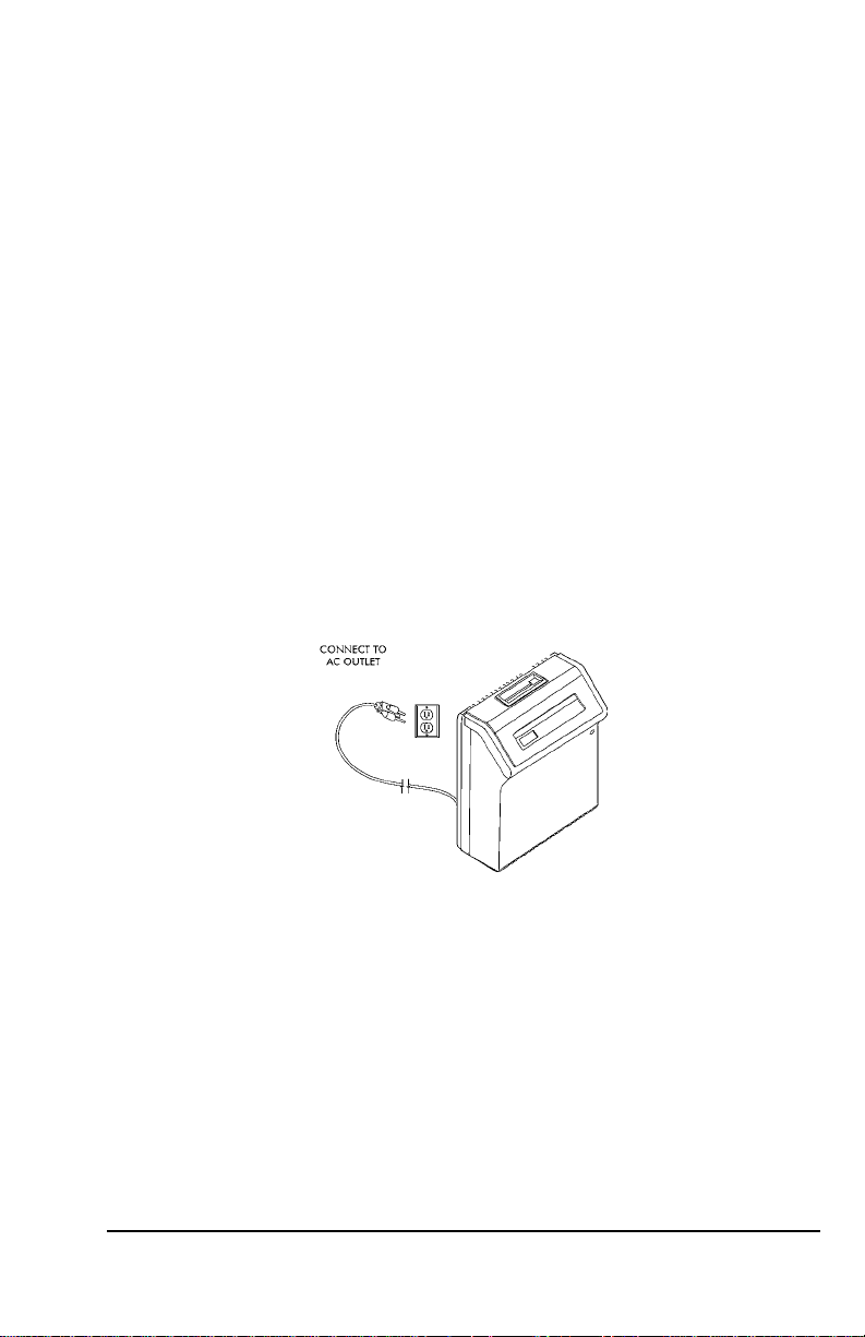
Power Connection
AC Power connections are made by plugging the power cord into a
suitable, grounded outlet.
CP-5000 User’s Guide 2-9
Page 18

Initialization and Reset
Prior to first use, the CP-5000 must be initialized to clear any possible
unexpected program parameters. Initialization (All Clear) erases all user
programming and resets the time and date to their default settings.
Reset Button
The Reset button can be pressed if the clock becomes unresponsiv e.
This has the same effect as cycling the power, and will not change the
time and date or erase any programming.
Insert a small screwdriver into the Reset Hole on the bottom of the unit
and press the Reset button.
Initialization (All Clear)
This function is provided to clear all programmed settings (weekly
programs, imprint formatting, etc.) from the CP-5000. When used, all
programming (including time, date and password) will be erased and the
unit will be returned to its default settings. You should only initialize your
CP-5000 prior to programming a new unit or when instructed to in the
Troubleshooting section of this manual.
Note: ESD (Electrostatic Discharge) precautions should be adhered to
when removing the top cover.
2-10 CP-5000 User’s Guide
Page 19
Initialize your CP-5000 as follows:
1. Remove the top cover. Set the Mode Switch to Program/Ink Mode.
2. Insert a small screwdriver into the Reset Hole on the bottom of the
unit and press and hold the Reset button.
3. While holding the Reset button, simultaneously press and hold the
Enter key and the Change key.
4. Release the Reset button; continue to hold
the Enter key and the Change key until five
rapid beeps sound, indicating a successful
reset to all default settings (showing a time of
12:00 AM on January 1, 2007). After a few moments, the clock will
return to its Enter Password mode.
5. Enter the default password (0000) and reprogram the unit as
desired. Set the Mode Switch to Normal and reinstall the top cover.
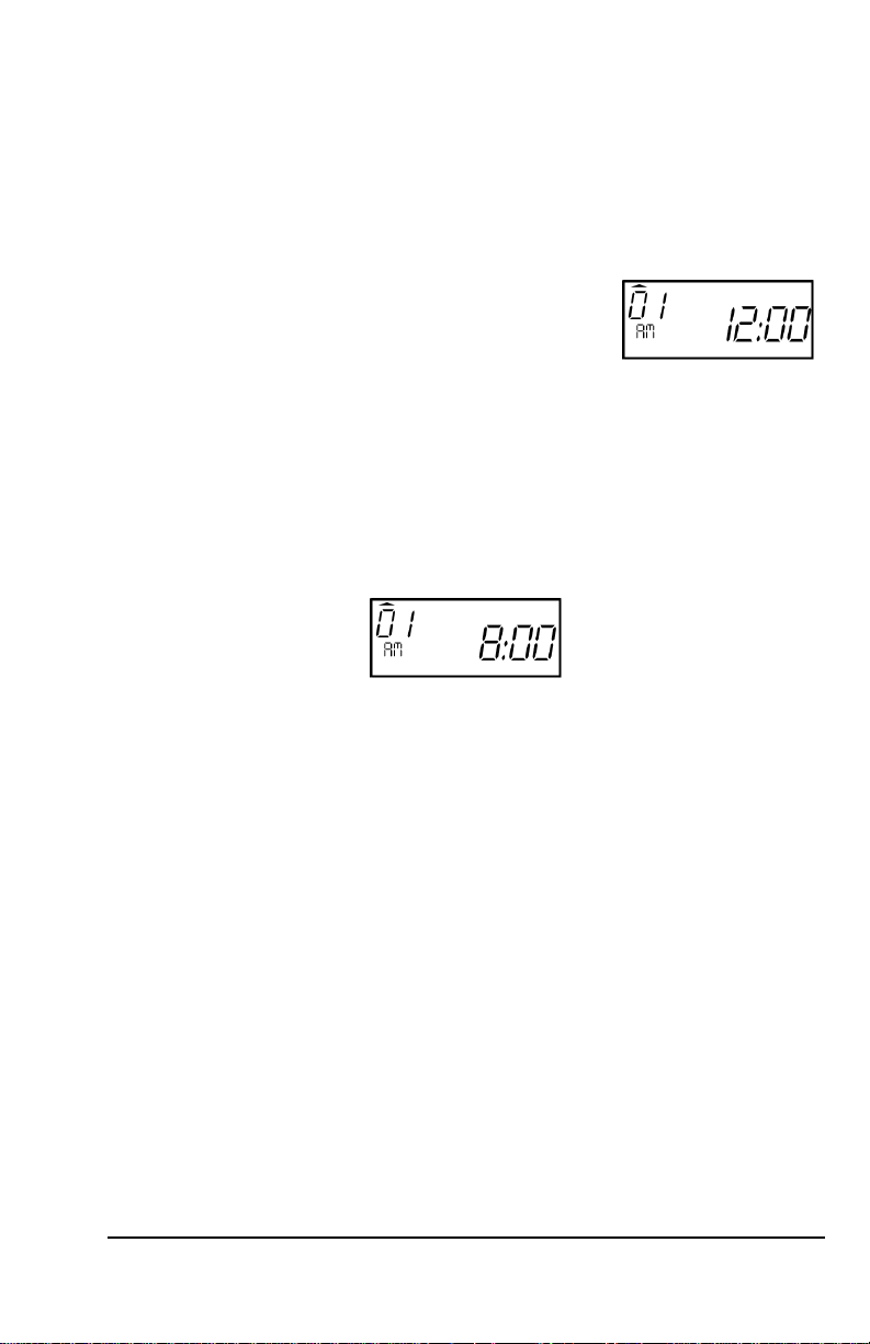
When the AC power is properly connected, the LED will cease to flash
and the LCD display will show normal time indication in the (12 hour)
format:
Note: If using the Full Power Reserve Battery, to insure premium
performance, it is recommended that the battery be fully charged
prior to use (approximately 24 hours).
Note: If using the Full Power Reserve Battery, to avoid damaging the
battery or draining it to an unrecoverable level, keep the machine
plugged into an AC power source during normal operation. The
Full Power Reserve Battery is intended for limited power outage
usage, and not as a power source during normal operations.
CP-5000 User’s Guide 2-11
Page 20

This page intentionally left blank.
2-12 CP-5000 User’s Guide
Page 21
Chapter 3: Time Cards
Making a Test Print
Follow these steps to make a test print:
1. Make sure that there is power to the CP-5000, and that the top cover
is in place.
2. Gently insert a time card into the card throat. The card will
automatically be fed in, printed and ejected. Do not force it in or
attempt to pull it out before it has been ejected.
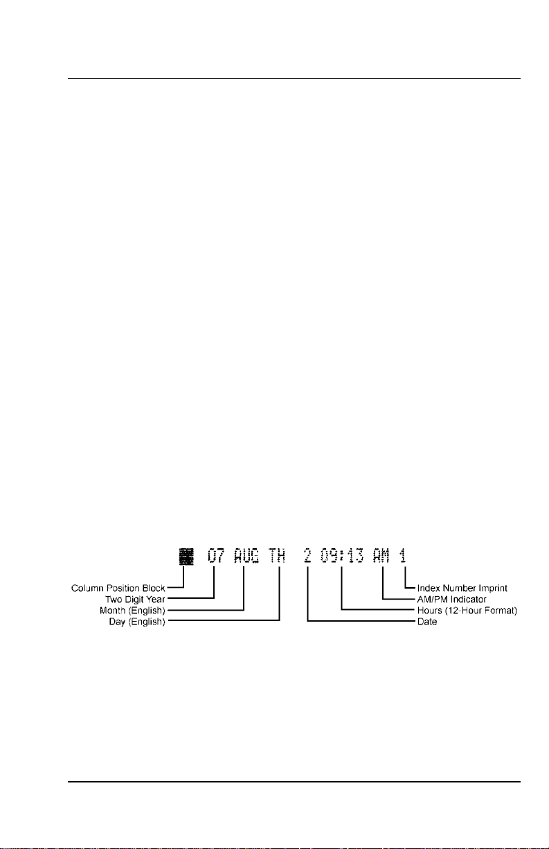
3. As shipped, the CP-5000 is configured to print in the following
format:
4. If this imprint is acceptable, the CP-5000 is ready to be programmed
for use (time and date). If you wish to change the style of the imprint,
you must program an imprint style for your application in addition to
setting the time and date for your CP-5000. Please refer to the Basic
Programming section of Chapter 4 to set year, time, and date
imprints.
CP-5000 User’s Guide 3-1
Page 22

This page intentionally left blank.
3-2 CP-5000 User’s Guide
Page 23

Chapter 4: Programming
Introduction
The CP-5000 must be programmed before use. There are two types of
programming: Basic and Weekly.
Basic Programming is used to program clock functions such as time,
date, time display, Daylight Saving Time (DST) adjustment, and card
imprint.
Weekly Programming consists of activating specific features of the CP5000 such as the activation of the built-in buzzer, triggering the relay
signal contacts, and changing the ribbon color at predetermined times of
the day and on specific days of the week.
General Programming Guidelines
Entering Program Mode
Note: ESD precautions should be observed when removing the top
cover.
To enter the Program Mode, remove the top cover and place the Mode
Switch in the Program/Ink position. After entering the password (page 4-
6), the first program menu/item (see Item 5 , page 4-13) will appear in
the display and the first LED indicator will illuminate.
CP-5000 User’s Guide 4-1
Page 24

Entering and Saving Values
Values are changed in each programming menu item by pressing the
Change key. Holding down the Change key for more than three seconds
will increment the value more rapidly in certain menu items. For example,
year values (07 to 50) will be incremented by a value of ten when the
Change key is pressed for more than three seconds.
To save values entered, press the Enter key. Some menus require that
several items be sequenced through before the parameters entered can
be saved.
All the parameters in the display will flash when an item is ready to be
saved. Pressing Enter will save the displayed parameters.
Exiting Program Mode or pressing the Function key will skip past the
item without saving.
Scrolling Through the Program Mode
While in the Program Mode, press the Function key to advance to the
next menu position. An LED indicator will light for each menu position.
Continue pressing the Function key and the cursor will eventually return
to the first menu.
Exiting Program Mode
To exit the Program Mode at any time, place the Mode Switch in the
Normal position.
4-2 CP-5000 User’s Guide
Page 25

Programming Guide
The following is a reference guide for programming the CP-5000:
Indicator Menu/
Item
11 Year
Description Display Accepted Values
(page 4-6)
07 to 50
12 Month and Date
13 Hour and
21 Daylight Saving
22 DST Begin
23 DST End
31
(page 4-6)
Minutes
(page 4-8)
(DST) Mode
(page 4-10)
(page 4-10)
(page 4-10)
Programming
Password
(page 4-6)
(Continued on next page)
Month: 01XX to 12XX
Date: XX01 to XX31
Hours: 00XX to 23XX
Minutes: XX00 to XX59
0: Disable
1: Date entry with rolling
calendar
2: Based on a specific date
Month: 01XX to 12XX
Date: XX01 to XX31
Month: 01XX to 12XX
Date: XX01 to XX31
0000: Disable
0001 to 9999: Password
CP-5000 User’s Guide 4-3
Page 26

Indicator Menu/
Item
41 Hour Display
42 Hour Imprint
Description Display Accepted Values
1: 24-hour format
(page 4-12)
(page 4-12)
2: 12-hour format (default)
1: 24-hour format
2: 12-hour format (default)
43 Fraction of Hours
44 Day Imprint
45 Year Imprint
46 Month Imprint
47 Date Imprint
Imprint
(page 4-12)
(page 4-12)
(page 4-13)
(page 4-13)
(page 4-13)
1: 60th hour (default)
th
hour
2: 10
3: 100 A (36 sec. = 0.01h)
4: 100 B (3 min. = 0.05h)
0: Off
1: Day of Week (1 to 7)
2: Day of Week (D1 to D7)
3: Day of Week (English)
(default)
4: Day of Week (Spanish)
5: Day of Week (French)
6: Day of Week (German)
7: Day of Week (Dutch)
8: Day of Week (Italian)
0: Off
1: On (default)
0: Off
1: Month (1 to 12)
2: Month (l to Xll)
3: Month (English) (default)
4: Month (Spanish)
5: Month (French)
6: Month (German)
7: Month (Dutch)
8: Month (Italian)
0: Off
1: On (default)
48 Index Number
Imprint
(page 4-14)
0: Off
1-99: Machine Index
Number
(Continued on next page)
4-4 CP-5000 User’s Guide
Page 27

Indicator Menu/
Item
51
01 to 80 Weekly Program
7
8
Description Display Accepted Values
Signal Duration
(page 4-14)
1 -15: Signal Duration
(seconds)
01 to 80 Programs
(page 4-15)
Program Printout
(page 4-18)
Diagnostics
(page 6-11)
0: Off
1: Program Printout
01: LED Test
02: Mode and Keys Test
03: LCD Test
04: Memory Test
05: Buzzer Test
06: Signal Test
07: Motor Test
08: Firmware Version No.
09: Print Counter
10: Card Print Test*
11: Crystal Adjustment*
12: Block Sensor Adjust*
13: Home Sensor Test*
14: Card Sensor Test*
15: Block Sensor Test*
16: Timing Sensor Test*
17: Block Read Test*
18: Sensor Rank Test*
*These tests are for factory use only.
CP-5000 User’s Guide 4-5
Page 28

Basic Programming
Programming Password (Menu 3)
Note: As supplied, the CP-5000 is configured with the default password
“0000”. Whenever a user removes the top cover to enter
programming mode, the clock will request a password by
displaying 0000. If no password has been configured by the
operator, then pressing Enter to accept the default and enter
programming mode. If security regarding clock settings is
important, it is recommended to configure a password other than
the default “0000” setting.
If a password has been programmed, it must be correctly entered in
order to modify any of the clock’s settings. Proceed as follows:
1. Remove the top cover. The display will show four
zeros, the first two of which will be flashing.
2. All passwords contain 4 digits. Using the Change
key, enter the first two digits of the password.
3. Select Enter. The last two digits will flash. Enter
the last two digits of the password.
4. Upon correct entry, the currently set month and
year will display as seen in the next section.
Note: If no password has been programmed, simply press Enter at the
four zero prompt.
Year, Month, and Date (Menu 1, Items 1 & 2)
Note: To set the year, month, and date, you must cycle through the
following sequence of displays for both items and save the data
entered. The data entered will not be saved if you exit the Program
Mode or press the Function key before completing each step.
1. Remove the top cover and enter the previously set password as
explained in the prior section. Upon correct password entry, the Year
menu item will flash in the display.
4-6 CP-5000 User’s Guide
Page 29

2. Press the Change key until the correct two digit
year (00 thru 50) is flashing in the display.
Holding down the Change key for more than
three seconds will increment the number in the
display by ten.
3. When the correct year appears, press the Enter
key. The display will automatically move to the
Month and Date menu item. The first pair of
digits (month) will flash in the display.
4. Press the Change key until the correct month number (01 thru 12)
appears in the display, then press the Enter key.
5. The next set of digits, the Date of the Month, will
flash in the display.
6. Press the Change key until the correct date of the month (01 thru
31) appears in the display, then press the Enter key.
7. The year, month, and date entered will flash
in the display (seen here: July 27, 2007). To
edit these settings, press the Change key.
This will return you to the display described
in step 1. To save these settings, press the
Enter key.
8. When the year, month and date are saved, the
next menu item, Hours and Minutes will appear
in the display.
Note: After saving the date, the LED indicator on the front panel will
automatically indicate the correct day of the week when returning
to Normal Mode.
CP-5000 User’s Guide 4-7
Page 30

Hours and Minutes (Menu 1, Item 3)
Note: To set the hours and minutes, you must cycle through the
following sequence of displays and save the data entered. The
data entered will not be saved if you exit the Program Mode or
press the Function key before completing all steps.
Note: All time programming is done in 24 hour time format, even if the
time is displayed in 12 hour time format. If you wish to change
the time format for the display, you must do so in the Hours
Display menu item.
1. Remove the cover and enter the pre-determined password. For
password entry information, refer to section Password Entry
Prior to Programming on page 4-6. Upon
correct password entry, the clock will enter the
PROGRAM MODE. The Year menu item will
automatically appear in the display.
2. If applicable, press the Enter key until the
Hours and Minutes menu item appears in
the display with the first pair of digits (hour)
flashing.
3. Press the Change key until the correct hour
(in 24 hour format, 00 thru 23) is flashing in
the display. Holding down the Change key for
more than three seconds will increment the
number in the display by ten.
4. When the correct hour appears, press the
Enter key. The second pair of digits, minutes,
will begin to flash.
5. Press the Change key until the correct
minutes (00 thru 59) appear in the display.
Holding down the Change key for more than
three seconds will increment the number in
the display by ten.
6. When the correct minutes appears in the
display, press the Enter key.
4-8 CP-5000 User’s Guide
Page 31

7. The hour and minutes entered will flash in the display. To edit these
settings, press the Change key. This will return you to the display
described in step 2. To save these settings, press
the Enter key. When saved, the next menu item,
Daylight Saving Change Time, will appear in
the display.
Daylight Savings Time (DST) (Menu 2)
The DST function can be programmed to operate in one of three
modes: change automatically each year by “rolling calendar;”
change automatically by a fixed date; or set inactive. By default,
the CP-5000 is configured for DST to be active, using the rolling
calendar mode and employing the expanded 2007 standard.
To program for DST, you must specify the date that the DST period will
begin and end. The time change will occur at 2:00 am on the begin and
end dates. At the DST Begin Date the time will increment by one hour,
and at the DST End Date the time will decrement by one hour.
Note: To set the DST Begin Date and End Date you must cycle
through the parameters for each item and save the data
entered. The data entered will not be saved if you exit the
Program Mode or press the Function key before completing
the steps as described.
Note: When setting the Begin Date and End Date for DST, you must
set those dates based upon the current year. This rule must be
applied regardless of whether the current date is within the DST
date span or not.
Automatic Adjustment Settings
There are three items to be configured for Daylight Saving Time setup:
• Menu 2, Item 1
set to 0: DST is disabled
set to 1: DST employs a rolling calendar. Set the DST start date
and end date once, and each year the correct DST change dates
will auto-calculate based upon the initial year’s settings.
Recommended.
Set to 2: DST employs a fixed calendar. Set the DST start date
and end date to this year’s dates, and each year that same date
will be employed for the DST change dates. Not generally
recommended.
CP-5000 User’s Guide 4-9
Page 32

• Menu 2, Item 2
Sets the DST start date’s month and date.
• Menu 2, Item 3
Sets the DST end date’s month and date.
Note: Setting the year is not necessary. If employing the rolling calendar
(Menu 2, Item 1, option 1), the year is understood to be the
current year and will be adjusted automatically into the future. If
employing a fixed calendar (Menu 2, Item 1, option 2), the month
and date are the same every year.
Programming DST (Menu 2, Items 1 – 3)
1. Remove the cover and enter the password. For password entry
information, refer to section Programming
Password on page 4-6. Upon correct password
entry, the clock will enter the PROGRAM MODE.
The Year menu item will automatically appear in
the display.
2. Select the Function key until mode 21 (DST)
appears.
3. Select the Change if a selection other than “1”
(default) is desired. This is the rolling calendar
option, and is the most common selection. Refer
to Menu 2, Item 1 on page 4-9 for details
regarding this option and others.
4. Select the Enter key twice. Mode 22 should
appear and the month and date will appear. On
this screen the start date for DST gets
programmed. The month flashes.
5. Select the Change key until the correct month (1-12) appears for the
start of DST. (For this example, programming for the year 2007 is
shown. You must set the start date and end date
for the current year, regardless of how far into
the year’s calendar when setting up DST. The
rolling calendar function will adjust future years
DST automatically based upon this initial setting.)
4-10 CP-5000 User’s Guide
Page 33

6. Select the Enter key, and now the date value
flashes. Select the Change key until the correct
date appears for the start of DST for the
selected year.
7. Select Enter and the entire screen flashes.
Select Enter again and Menu item 23 appears.
In this menu the end date for DST can be
programmed.
8. Select the Change key until the correct month
(1-12) appears for the end of DST. (For this
example, programming for the year 2007 is
used.)
9. Select the Enter key, and now the date value
flashes. Select the Change key until the correct
date appears for the end of DST for the selected
year.
10. Select Enter and the entire screen flashes. Select Enter again and
the Save process is complete. The top cover may be returned to its
normal position.
Disabling DST
1. Remove the cover and enter the password. For password entry
information, refer to section Password Entry
Prior to Programming on page 4-6. Upon correct
password entry, the clock will enter the Program
Mode. The Year menu item will automatically
appear in the display.
2. Select the Function key until mode 21 (DST) appears.
3. Select the Change key once so that “0” is
selected. This is the DST Disabled option.
4. Select the Enter key twice, then return the top
cover. The DST function is now disabled.
CP-5000 User’s Guide 4-11
Page 34

Hours Display and Imprint (Menu 4, Items 1 – 7)
This group of menu items is used to set the time format (12 or 24 hour)
of the display in Normal Mode and the imprint that will appear on the time
card. To set the hours displayed and/or imprint proceed with the
following steps:
1. Enter the Program Mode and press the Function key until the Item
1 - Hours Display appears in the display.
2. Press the Change key to select a value of “1” for
24-hour time format or “2” for 12-hour time
format.
3. When the desired value appears, press the Enter key. The display
will automatically move to Item 2 - Hour Imprint.
4. Press the Change key to select a value of “1” for
24-hour time format or “2” for 12-hour time
format. If “2” is selected, an “AM” or “PM” will
appear after the time in the imprint.
5. When the desired value appears, press the
Enter key. The display will automatically move
to Item 3 - Fraction of Hours (Minutes) Imprint.
6. Using the Change key, select one of the
following:
Accepted Values Imprint
1 60
2 10
3 100th A’ (36 sec. = 0.01h)
4 100th B (3 min. = 0.05h)
th
th
hour
hour
7. When the desired value appears, press the Enter
key. The display will automatically move to Item 4 Day Imprint.
4-12 CP-5000 User’s Guide
Page 35

8. Using the Change key, select one of the following:
Accepted Values Imprint
0 Off
1 Day of Week (1 to 7)
2 Day of Week (D1 to D7)
3 Day of Week (English)
4 Day of Week (Spanish)
5 Day of Week (French)
6 Day of Week (German)
7 Day of Week (Dutch)
8 Day of Week (Italian)
9. When the desired value appears, press the
Enter key. The display will automatically move
to the Item 5 - Year Imprint.
10. Press the Change key to select a value of “0” for no year imprint
(OFF) or “1” to include the year in the imprint (ON).
11. When the desired value appears, press the
Enter key. The display will automatically move
to the Item 6 - Month Imprint.
12. Using the Change key, select one of the following:
Accepted Values Imprint
0 None
1 Month (1 through 12)
2 Month (l through Xll)
3 Month (English) (default)
4 Month (Spanish)
5 Month (French)
6 Month (German)
7 Month (Dutch)
8 Month (Italian)
13. When the desired value appears, press the Enter key. The display
will automatically move to the Item 7 - Date Imprint.
14. Press the Change key to select a value of “0” to
disable this feature or “1” to include an additional
day of the month (00 to 31) in the imprint.
CP-5000 User’s Guide 4-13
Page 36

15. When the desired value appears, press the Enter
key. When saved, the next menu item, Index No.
Imprint, will appear in the display.
Index Number Imprint (Menu 4, Item 8)
This menu item is used to identify individual time clocks by printing a
time clock-assigned code number onto the time card. The Index Number
may be any number between 01 through 99.
Note: To disable the Index Number Imprint, enter “00”.
1. Enter the Program Mode and press the Function
key until the Index No. Imprint menu item appears
in the display.
2. Press the Change key to select a value of 00 thru 99 that will be
used to identify this time clock on a time card.
3. When the desired value appears, press the Enter key. The display
will automatically move to the Signal Duration menu item.
Signal Duration (Menu 5, Item 1)
This selection is used to set the duration (in seconds) that the relay
contacts of the installed signal device will be closed. It also defines the
time the internal buzzer will sound.
1. Enter the Program Mode and press the Function
key until the Signal Duration menu item appears in
the display.
2. Press the Change key to select a duration of one to fifteen seconds
that relay contacts of the signal device will be closed.
Note: While setting a one second duration is possible, it is not
recommended.
3. When the desired value appears, press the Enter key. The display
will automatically move to the Weekly Programming menu item.
4. Exit the Program Mode by re-installing the top cover, which
automatically switches the unit to Normal Mode.
4-14 CP-5000 User’s Guide
Page 37

Weekly Programming (Items 01 – 80)
This menu allows you to create a weekly schedule that will enable or
disable certain features of the CP-5000 at predetermined times of the
day and on specific days of the week. This schedule is comprised of two
components: Moments and Objects. They are:
Moments Objects
Days of the Week Built-in Buzzer
Time of the Day Signal
Color of Imprint
Note: Days are indicated numerically, and begin on Monday (1) and end
on Sunday (7).
Functions Available in Weekly Programming
• Buzzer: Menu code number 1. This function activates a small internal
buzzer, providing a locally-heard audible signal of medium tone. The
duration of time for the buzzer’s signal is controlled by the Signal
function, next.
• Signal: Menu code number 2. This function activates the internal
relay controlling an external signal device.
Note: The duration (1 to 15 seconds) that the relay and buzzer will be
ON for is set in the Signal Duration (page 4-14) menu item.
• Ink Color Selection: Menu code number 3.
Up to eighty Weekly Programs or schedules can be entered into the
CP-5000. Programming charts are provided in the Appendix to help you
set up weekly programs. A sample Weekly Program is shown in the
following table:
Pgrm
No.
Days Time 1. Buzzer 2. Signal 3. Color
1 2 3 4567HH:MM
01 X X X 08:27 0 1 1
02 X X X 10:12 1 0 2
In this example, at 8:27 am, on the second (Tuesday), fourth (Thursday),
and fifth (Friday) day of the week, the external signal will activate and the
CP-5000 will print in black ink. At 10:12 am on the same days, the built-in
buzzer will sound and the CP-5000 will print in red ink.
Moment Code Number / Object
0: Off
1: On
0: Off
1: On
0: No Change
1: Black
2: Red
CP-5000 User’s Guide 4-15
Page 38

Creating a Weekly Program
Note: To create a program or schedule, you must cycle through the
sequence of displays of each program number and save the data
entered. The data entered will not be saved if you exit the
Program Mode or press the Function key before completing each
sequence.
1. Enter the Program Mode and press the Function
key until the Weekly Program menu item appears
in the display. The first program number will
appear, with the first cursor or day of the week
(Monday) flashing in the display.
2. Press the Change key to (deselect) omit days of
the week from the schedule or press the Enter
key to (select) include days of the week on the
schedule. Days that the schedule will operate on
will be shown in the display as cursors.
3. When the days of the week are selected, the
display will flash the hour of the selected days
that the schedule will be activated.
Note:
All time programming is done in 24 hour time format.
4. Press the Change key until the hour of the day
(00 thru 23) appears in the display, then press the
Enter key. The digits that represent the minutes
of the hour will appear and flash in the display.
5. Press the Change key until the correct minutes
(00 thru 59) appear in the display, then press the
Enter key. This is the time (hours and minutes)
that the schedule will be activated on the selected
days of the week. The display will move to the
Buzzer, which is the first object to be turned on or
off in the schedule.
6. Press the Change key to enter a value of “0” to
disable (OFF) or “1” to enable (ON) the Buzzer.
When the correct value appears in the display,
press the Enter key. The display will move to the
next object, Signal.
4-16 CP-5000 User’s Guide
Page 39

Note: The duration (1 to 15 seconds) that the Buzzer will be ON for is
set in the Signal Duration menu (page 4-14).
7. Press the Change key to enter a value of “0” to
disable (OFF) or “1” to enable (ON) Signal.
When the correct value appears in the display,
press the Enter key. The display will move to
the next object, Color.
Note: The duration (1 to 15 seconds) that the relay contacts of Signal
will be closed is set in the Signal Duration menu (page 4-14).
8. Press the Change key to enter a value of “1” to
change to black ink, or “2” to change to red ink.
Note: If you program a color change, you must
program another step or schedule to return the ribbon to its
original color.
9. When the desired value is displayed, press Enter
key. The program number, days of the week, and
time of the day that the program will be activated
will flash in the display. To edit these settings,
press the Change key. This will return you to the
display described in step 1. To save these
settings, press the Enter key. When saved, the
display will move to the next program number.
10. Repeat the previous steps to enter in the next
program. If a mistake is made at any time, the
fastest way to return to the Weekly program to
be changed is to select the Function key and
cycle through the other programming options
until the Weekly programming reappears.
Warning!: Do not schedule to programs to occur at the same time;
the results will be inconsistent and unpredictable.
CP-5000 User’s Guide 4-17
Page 40

Obtaining a Printout of Programmed Data (Menu 7)
1. If you have not already done so, enter the Program Mode and press
the Function key until the Program Printout menu item (7) appears
in the display. The default value of this item is
zero or OFF.
2. Press the Change key to change the value in
the display to “1” or ON.
3. With “1” flashing in the display, press the Enter
key. The “1” will cease to flash.
4. Insert a time card. All Basic Programming
information will be printed on the time card. The information will be
printed in red ink.
5. If you have programmed one or more Weekly Programs, insert
another time card (or the reverse side of the one used in step 4) to
obtain a printout. Up to twenty Weekly Programs are printed per
card.
In the sample above, program one (STP column: 01) is configures.
For that event, which takes place Mondays and Tuesdays (DAYS
column: 1 and 2) at 10:00 a.m., the buzzer (BZR) will sound, the
relay (RLY) will close, and the ink (CLR) will change to red color.
4-18 CP-5000 User’s Guide
Page 41

There are no programmed events for programs two and three (STP 2
or STP 3).
6. To stop printing at any time, press and hold either the Change or
Enter key. Only the currently inserted time card will be printed on,
and the remainder of the programming data will not be printed.
7. When printing is completed, the display will automatically move to
the next menu. Exit the Program Mode to Normal Mode by re-
installing the top cover.
Editing Weekly Programs
1. Obtain a printout of the current Weekly Programs.
2. Mark on the printout the desired Weekly Program that you want to
change.
3. Enter the Program Mode and press the Function key until the
Weekly Program menu item appears in the display.
4. Press and hold the Enter key until the desired program number
appears. To move to previously numbered Weekly Programs, press
and hold the Change key.
5. Change the Weekly Program as desired. For the changes to be in
saved, you must cycle through the sequence of parameters for the
program and press Enter to save your changes.
6. After saving the program, press the Function key to move to the
Program Printout menu item and print out a copy of the program to
verify your changes.
Adding Additional Weekly Programs
1. Obtain a printout of the current Weekly Programs.
2. Mark the last Weekly Program on the printout.
3. Enter the Program Mode and press the Function key until the
Weekly Program menu item appears in the display.
4. Press and hold the Enter key until an empty Weekly Program
appears in the display. The program number should be the last
program number on the printout + 1.
5. Enter the program parameters as desired. For the changes to be in
saved, you must cycle through the sequence of parameters for the
program and press Enter to save your changes.
6. After saving the program, press the Function key to move to the
Program Printout menu item and print out a copy of the program to
verify your settings.
CP-5000 User’s Guide 4-19
Page 42

Deleting a Weekly Program
Note: Weekly Program number 1 can not be deleted.
1. Obtain a printout of the current Weekly Programs.
2. Mark on the printout the desired Weekly Program that you want to
delete.
3. Enter the Program Mode and press the Function key until the
Weekly Program menu item appears in the display.
4. Press and hold the Enter key until the desired weekly program
number appears. To move to previously numbered Weekly
Programs, press and hold the Change key.
5. Press the Change key to delete all days of the week that the
program was scheduled for.
6. All the objects in the program will flash in the display.
7. Press the Enter key to delete this program. The remainder of the
programs in the CP-5000 will automatically have their program
number moved down one to fill the empty space left by the program
that was just deleted. For example, if program number seven was
deleted, program number eight will now be program number seven.
8. After saving the program, press the Function key to move to the
Program Printout menu item and print out a copy of the program to
check.
4-20 CP-5000 User’s Guide
Page 43

Chapter 5: Maintenance
Service
With the exception of the ribbon and the time/date memory backup
battery, there are no user-serviceable parts in the time recorder. Do not
attempt to service/disassemble the time recorder other than prescribed in
this manual.
Exterior
Gently wipe the exterior of the unit with a soft cloth dampened with water
and a neutral detergent. Do not use thinner, benzene, or similar solvent.
Ribbon Replacement
The ribbon should be replaced when the imprint of the time card appears
light, overprinting (one line of print overlapping another) occurs or when
the following message appears in the display:
Always use Amano-approved ribbons. Non-Amano rib bons bind in the
printer carriage, produce weak quality prints and leave ink residue on
print head, rollers, and time cards.
Perform the following steps to replace the ribbon:
1. Remove the top cover and set the Mode Switch to Program/Ink.
2. Grasp the front panel from the bottom and flip it up.
3. Using two fingers, press the two white release tabs down and
towards the case, and while holding them, remove the ribbon.
CP-5000 User’s Guide 5-1
Page 44

4. Insert a new ribbon between the ribbon guide and the printer head.
5. Press the ribbon down until it clicks into place. Turn the knob
clockwise to remove any slack in the ribbon.
6. Rotate the front panel down until it clicks in place.
7. Set the Mode Switch back to Normal and replace the top cover.
8. Insert a time card into the card throat to check the printing quality
and to confirm that you have installed the ribbon properly.
5-2 CP-5000 User’s Guide
Page 45

Time/Date Memory Backup Battery
Amano recommends the replacement of this battery every five years.
The battery maintains the time and date settings in the CP-5000 during
power interruptions.
Perform the following steps to replace the battery:
1. Disconnect the power cord from the AC outlet.
Warning!: Do not proceed without disconnecting AC power. A
serious shock hazard exists when the front cover is off
and AC power is applied.
2. Remove the top cover.
3. Remove the front cover (see Chapter 2).
4. Using an insulated tool (plastic screwdriver, toothpick, etc.) push up
lightly on either bottom corner of the battery to lift it partially out of
the battery holder. Grasp the top of the battery and lift it out of the
holder.
5. Install the new battery with the positive (+) side facing you. Press
down until the battery is fully seated in the battery holder.
6. Replace the front cover.
CP-5000 User’s Guide 5-3
Page 46

7. Plug the power cord into the AC outlet.
8. Reprogram the date and time.
Note: If the Full Power Reserve Battery option is installed, it might not
be necessary to reprogram the date and time; verify the settings
before proceeding.
9. Replace the top cover.
5-4 CP-5000 User’s Guide
Page 47

Chapter 6: Troubleshooting
Introduction
If your CP-5000 should fail to operate properly, you should perform the
following to determine the cause:
• Visually inspect the unit.
• Obtain a printout of programmed data and verify the programming.
• Check that AC power is connected.
• Check the condition of the time card, if it is dirty or damaged, it must
be replaced.
• Run the specified test in the Diagnostics menu.
• Press the Reset key.
• Reinitialize the unit to reset the unit to defaults.
If, after performing the above, you still are unable to resolve the problem
or feel that your unit requires servicing, contact your local Amano dealer.
General Problems
Signal
If you are experiencing a problem with the relay signal circuit, you
should perform the following:
• Verify that the connections to TB1 (page 2-6) are correct.
• Verify that the external device is working properly.
• Verify that the maximum load is not exceeded.
• Check to see that the appropriate surge absorber is properly
connected to the external device.
• Check all wiring.
• Obtain a printout of programmed data in your CP-5000. Verify that
Signal is correctly programmed in the Weekly Program.
CP-5000 User’s Guide 6-1
Page 48

• Run the Signal Test from the Diagnostics menu to check if the
Signal relay is operating properly. If it is not, contact your local
Amano dealer.
Foreign Object or Material
Only a time card should be inserted into the unit. If foreign objects or
materials get inside the CP-5000, you must disconnect the AC power
and the battery, and remove the foreign objects.
Programming
If you suspect a programming problem, it is recommended that you
obtain a printout of the programmed information as described in
Chapter 4 and troubleshoot the programmed data, or initialize the clock
(page 2-10) to reset the unit to defaults.
If you are unable to resolve the problem, please contact your local
Amano dealer.
Key Failure
If you suspect that one of the keys has failed, you should run the Key
Test in the Diagnostics menu.
Audible Beeps
The time recorder is equipped with an audible alarm that “beeps”. The
beeps will vary in duration and corresponding meaning (see the
following).
6-2 CP-5000 User’s Guide
Page 49

Error Messages
There are nine possible error messages (Err 1 thru Err 9) that can
appear in the display. When one of the errors occur, the CP-5000 will
display the error message and may beep. The display will return to
normal after an error message is displayed.
Err 1 thru Err 9
Printing or Ribbon Error
The time card sensors could not detect the Column Position Block.
Possible reasons are:
• The imprint quality (black color) is poor or too light. Replace the
ribbon cassette.
• No ribbon cassette is inside the machine. Install a ribbon cassette.
• The ribbon cassette is not seated correctly in the printer carriage.
Reinstall the ribbon cassette.
• The red color is active in front of the dot head. This is due to
normal interference between the slider and printer carriage. Push
slider to normal (protruding from the left side of the printer carriage)
position.
• Printer or printer carriage is damaged. Contact your local Amano
dealer.
• A non-Amano ribbon was used. Always use Amano approved
ribbons: non-Amano ribbons bind in the printer carriage, produce
weak quality prints and ink residue on print head, rollers, and time
card.
CP-5000 User’s Guide 6-3
Page 50

• The slider on the printer carriage is not moving correctly due to a
missing black plastic bushing in the small holes on the right or left
side of the printer frame. Contact your local Amano dealer.
• There is dirt, oil, dust, or ink residue on the surface of the time card
or the time card surface is too rough for the time card sensor to
detect the Column Position Block. Replace the card.
• The background color of the time card is too dark.
Time Card Error
When this message is displayed, printing will stop immediately. This
occurs when the time card is pushed or pulled when fed into the card
throat or during the printing cycle.
Time Card is Full
This message indicates that the time card is full; no more space is
available for printing.
Invalid Card Edge Detection
The block sensor is not detecting the edge of the card. Possible causes
are:
• The rubber roller in the card transport mechanism is dirty. The roller
can be cleaned with Fantastik
cotton swab. Be sure to completely dry all residue.
6-4 CP-5000 User’s Guide
®
spray cleaner on a clean cloth or
Page 51

• The block sensor is malfunctioning. If this condition persists, contact
your local Amano dealer.
Card not in Clock
This message will be displayed if the card is not pulled into the transport
mechanism after five attempts. This can occur if someone fails to release
the card when attempting a punch.
Block Read Sensor Error
The block sensor is not detecting the Column Position Block after
printing due to the card not moving (due to slippage or interference) or a
block sensor malfunction. If this condition persists, contact your local
Amano dealer.
CP-5000 User’s Guide 6-5
Page 52

Timing Sensor Error
This error occurs when a card gets stuck or irregular card motion is
detected by the card transport mechanism. Possible causes are:
• A non-standard time card shape is used or the time card is forced
into the card throat. In either case, the time card sensors detect the
presence of the time card, but the unit is unable to flush out the card.
The time card has to be removed manually to resolve this problem.
• The rubber roller in the card transport mechanism is dirty. The roller
should be cleaned; see page 6-4 for details.
• The time card feed mechanism or time card sensors are damaged.
Password Error
This message is displayed when an invalid password is entered when
attempting to access programming mode.
Real Time Clock Error
This error indicates an unexpected clock value.
Blank Display
When this condition occurs, the CP-5000 will also emit a continuous
beep. If possible, perform the LCD Test in the Diagnostics menu. If this
condition persists, contact your local Amano dealer.
6-6 CP-5000 User’s Guide
Page 53

Display Related Problems
Low Battery
If the accessory battery is installed and operating the clock during a
power failure, this display indicates that the battery is weak. During this
low battery display indication, the time and date will be maintained. The
number of prints made should be kept to a minimum to conserve power.
There will be no loss of programmed data. The clock will return to normal
operation when AC power is restored.
If there is no damage to the battery, the battery will be recharged by the
AC power supply when power is restored. Please allow the CP-5000 24
hours to recharge the battery completely.
Power Failure
A blinking LED and constant colon in the display indicates an AC power
failure. When this occurs, the operation of the CP-5000 is taken over by
the internal battery.
If AC power is connected and working, and the display indicates a power
failure, contact your local Amano dealer.
Inaccurate Clock
The clock frequency is factory set. If you feel that your clock is
inaccurate, please contact your local Amano dealer.
LED’s Not Functioning
If the LED’s fail to function on the front panel, run the LED test in the
Diagnostics menu. If the problem is not resolved, contact your local
Amano dealer.
CP-5000 User’s Guide 6-7
Page 54

Hour Change
If the time displayed is off by an hour (either up or down), one of the
following may have occurred:
• The programmed DST settings are incorrect.
• The Enter or Change key was inadvertently pressed.
Card Feed Problems
Card Refused
• Check whether the column of your time card is already completely
filled with imprints. If all positions are already occupied by an imprint,
two beeps will sound, and the card will be rejected without making an
imprint.
• Check the condition of the time card. If there is dirt, oil, dust, or ink
residue on the card, the time card sensors cannot read the Column
Position Block.
• Verify the imprint position. If the Column Position Block is
positioned on artwork or a column line, the time card sensor will read
this as a column full condition.
• A non-Amano ribbon was used. Always use Amano approved
ribbons, non-Amano ribbons bind in the printer carriage, and produce
weak quality prints, and ink residue on print head, rollers, and time
card.
• The background color of your time card is too dark
Card Cannot Enter or Card Blocked
When you insert a time card into the card throat, the feed motor will
grasp it and pull it down to be printed. The feed motor will attempt to
grasp the card a maximum of three times. If the third attempt fails, a
long beep will sound, the feed motor will shut off, and the card must be
manually removed from the card throat.
If a card is blocked or stuck inside the card throat after the imprint has
been printed, the feed motor will attempt to flush out the card a maximum
of three times. If the card is still inside the card throat after the third
attempt, the feed motor will shut down, leaving the card inside the unit. If
the card was unable to be flushed out by the feed motor, it must be
manually removed.
6-8 CP-5000 User’s Guide
Page 55

Card Refused, Date and Time in Display
If a time card is inserted into the card throat, refused, and a beep
sounds, the time card is too short. The time card sensors compare the
top margin of the time card with the imprint position. If it can not reach
this imprint position, the unit will beep and refuse the card.
Imprint Problems
Overprint
The Column Position Block in the imprint is used by the CP-5000 to
prevent overprinting. If your CP-5000 is overprinting, any one of the
following may be the cause:
• The time card was pushed, pulled, or moved during the printing cycle
causing the time card sensors to misinterpret the Column Position
Block.
• The quality of the ribbon is poor. The system can not detect a weak
Column Position Block.
• A non-Amano ribbon was used. Always use Amano approved
ribbons: non-Amano ribbons bind in the printer carriage, produce
weak quality prints and ink residue on print head, rollers, and time
card.
• The background color of the time card is too dark.
• The surface of the time card is too rough or there is dirt, oil, dust, or
ink residue on the card.
Imprint Position Wrong
If your CP-5000 is functioning normally, but the position of the imprint is
incorrect, perform the following:
• Verify that the programmed date and time are correct.
• A non-Amano ribbon was used. Always use Amano approved
ribbons: non-Amano ribbons bind in the printer carriage, produce
weak quality prints and ink residue on print head, rollers, and time
card.
• The feed rollers may be damaged or require cleaning. Contact your
local Amano dealer.
CP-5000 User’s Guide 6-9
Page 56

Wrong Color Printed
The CP-5000 has the ability to print in red or black ink. When the top
cover is installed (Normal Mode), the default ink color is black, and the
color of ink printed is determined by the settings in the Weekly Program.
When the top cover is removed (Program Mode), the CP-5000 will print
in red. If the wrong color is being printed by your CP-5000, please
perform the following:
• Obtain a print out of the programmed data from the CP-5000. Verify
that your Weekly Program settings are correct.
• The red color is active in front of the dot head. This is due to normal
interference between slider and printer carriage. Push slider to
normal position.
• Printer or printer carriage is damaged. Contact your local Amano
dealer.
• The slider on the printer carriage is not moving correctly due to a
missing black plastic bushing in the small hole of the right printer
frame. Contact your local Amano dealer.
• The ribbon cassette is not seated correctly in the printer carriage.
Reinstall the ribbon cassette.
• Printer or printer carriage is damaged. Contact your local Amano
dealer.
Weak or Light Printing
Please refer to Printing or Ribbon Error Message, Err1 section of this
chapter for troubleshooting weak or light printing problems.
6-10 CP-5000 User’s Guide
Page 57

Diagnostics (Menu 8)
The Diagnostics Menu is used to run specific diagnostic routines for
troubleshooting and determining the condition of your CP-5000.
The Diagnostics menu is accessed by entering the Program Mode, and
pressing the Function key until the LED Test (Menu 8, Item 1) appears
in the display and the last LED indicator is illuminated.
The general guidelines for the Diagnostics Menu are as follows:
• Each test is indicated by a specific number (refer to the
Programming Guide, page 4-3) flashing in the display.
• To select and start a test, press the Enter key.
• To stop a test press the Enter key again. A beep will sound and the
test number will flash in the display.
• Press the Change key to move to the next test.
• Press the Function key to leave the Diagnostics Menu.
LED Test (Menu 8, Item 1)
1. If you have not already done so, enter the Program Mode and press
the Function key until the LED Test menu
item appears in the display.
2. Press the Enter key to select and start the
test. The test number will cease to flash in the
display, and the LED indicators will illuminate
one at a time from left to right.
3. Press the Enter key to stop the test. A beep
will sound and the test number will flash in the
display.
4. Press the Change key to move to the next test
or exit the Diagnostic Menu by pressing the
Function key, or by exiting the Program Mode.
CP-5000 User’s Guide 6-11
Page 58

Mode and Keys Test (Menu 8, Item 2)
1. If you have not already done so, enter the Program Mode and press
the Function key until the LED Test menu item
appears in the display.
2. Press the Change key. The Mode and Keys
Test menu item will appear in the display.
3. Press the Enter key to select and start the test.
The test number will cease to flash in the
display, and the first LED indicator (on the left
side of the front panel) will illuminate
4. Place the Mode Switch in the Normal position.
The LED indicator should turn off.
5. Set the Mode Switch back to Program/Ink. The LED indicator should
illuminate. Repeat this sequence several times.
6. To test the keys, place the Mode Switch in the Normal position. The
LED indicator should turn off.
7. Press the Function key, the second LED indicator will illuminate.
8. Press the Enter key, the third LED indicator will illuminate.
9. Press the Change key, the fourth LED indicator will illuminate.
Repeat this sequence several times.
10. Set the Mode Switch back to Program/Ink and press the Enter key
to stop the test. A beep will sound and the test number will flash in
the display.
11. Press the Change key to move to the next test
or exit the Diagnostics Menu by pressing the
Function key, or by exiting the Program Mode.
6-12 CP-5000 User’s Guide
Page 59

LCD Test (Menu 8, Item 3)
1. If you have not already done so, enter the Program Mode and press
the Function key until the LED Test
menu item appears in the display.
2. Press the Change key twice. The LCD
Test menu item will appear in the display.
3. Press the Enter key to select and start
the test. The test number will disappear
and all the segments of the LCD display
will flash.
4. Press the Enter key to stop the test. A
beep will sound and the test number will
flash in the display.
5. Press the Change key to move to the
next test or exit the Diagnostics Menu by
pressing the Function key, or by exiting
the Program Mode.
EPROM (Memory) Test (Menu 8, Item 4)
1. If you have not already done so, enter the Program Mode and press
the Function key until the LED Test menu
item appears in the display.
2. Press the Change key three times. The
EPROM Test menu item will appear in the
display.
3. Press the Enter key to select and start the
test. The test number will cease to flash in
the display, and the second LED will
illuminate and the size of the EPROM will be
in the display.
CP-5000 User’s Guide 6-13
Page 60

4. Press the Enter key to stop the test. A beep will
sound and the test number will flash in the
display.
5. Press the Change key to move to the next test or
exit the Diagnostics Menu by pressing the
Function key, or by exiting the Program Mode.
Buzzer Test (Menu 8, Item 5)
1. If you have not already done so, enter the
Program Mode and press the Function key until
the LED Test menu item appears in the display.
2. Press the Change key four times. The Buzzer
Test menu item will appear in the display.
3. Press the Enter key to select and start the test.
The test number will cease to flash in the display,
and the Buzzer will sound for a maximum of eight
beeps.
4. Press the Enter key to stop the test. A beep will
sound and the test number will flash in the
display.
5. Press the Change key to move to the next test or
exit the Diagnostics Menu by pressing the
Function key, or by exiting the Program Mode.
6-14 CP-5000 User’s Guide
Page 61

Signal Test (Menu 8, Item 6)
1. If you have not already done so, enter the
Program Mode and press the Function key until
the LED Test menu item appears in the display.
2. Press the Change key five times. The Signal
Test menu item will appear in the display.
3. Press the Enter key to select and start the test.
The test number will cease to flash in the display
and you will hear a clicking sound as the relay
contacts open and close.
4. Press the Enter key to stop the test. A beep will
sound and the test number will flash in the
display.
5. Press the Change key twice to move to the next
test or exit the Diagnostics Menu by pressing the
Function key, or by exiting the Program Mode.
Motor Test (Menu 8, Item 7)
1. If you have not already done so, enter the
Program Mode and press the Function key until
the LED Test menu item appears in the display.
2. Press the Change key six times. The Motor Test
Number menu item will appear in the display.
3. Press the Enter key to select and start the test.
The test number will cease to flash in the display and you will hear
the sounds of the motor whirring. The cycle completes in a few
seconds.
4. Press the Enter key to complete the test. A beep will sound and the
test number will flash in the display.
5. Press the Change key to move to the next test or
exit the Diagnostics menu by pressing the
Function key, or by exiting the Program Mode.
CP-5000 User’s Guide 6-15
Page 62

Firmware Version Number (Menu 8, Item 8)
1. If you have not already done so, enter the
Program Mode and press the Function key until
the LED Test menu item appears in the display.
2. Press the Change key seven times. The
Firmware Version Number menu item will appear
in the display.
3. Press the Enter key to start the version display
function. The test number will cease to flash in the
and the firmware version will display.
4. Press the Enter key to stop the test. A beep will
sound and the test number will flash in the
display.
5. Press the Change key to move to the next test
or exit the Diagnostics menu by pressing the
Function key, or by exiting the Program Mode.
Print Counter (Menu 8, Item 9)
1. If you have not already done so, enter the
Program Mode and press the Function key until
the LED Test menu item appears in the display.
2. Press the Change key eight times. The Print
Counter menu item will appear in the display.
3. Press the Enter key to select and the print counts.
A beep will sound and the number of imprints the
clock has made will be displayed.
4. Press the Enter key to complete the test. A beep
will sound and the test number will flash in the
display.
5. Press the Function key to exit the Diagnostics menu, or exit
Program Mode.
Card Print Test (Menu 8, Item 10)
This test, for factory use only, will sequentially print on a time card until it
is full. It is not recommended for field use as it rapidly consumes the ink
ribbon.
Calibration & Sensor Tests (Menu 8, Items 11 - 18)
These are calibration tests for factory use only.
6-16 CP-5000 User’s Guide
Page 63

Chapter 7: Appendix
The following blank chart is provided to assist you in creating Weekly
Programs for your CP-5000.
Program
No.
Days Time 1. Buzzer 2. Signal 3. Color
1 2 3 4567HH:MM
01 :
02 :
03 :
04 :
05 :
06 :
07 :
08 :
09 :
10 :
11 :
12 :
13 :
14 :
15 :
16 :
17 :
18 :
19 :
20 :
21 :
22 :
23 :
24 :
25 :
26 :
27 :
28 :
29 :
30 :
Moment Object
0: Off
1: On
0: Off
1: On
0: No Change
1: Black
2: Red
(Chart continued on next page)
CP-5000 User’s Guide 7-1
Page 64

Program
No.
Days Time 1. Buzzer 2. Signal 3. Color
1 2 3 4 5 6 7 HH:MM
31 :
32 :
33 :
34 :
35 :
36 :
37 :
38 :
39 :
40 :
41 :
42 :
43 :
44 :
45 :
46 :
47 :
48 :
49 :
50 :
51 :
52 :
53 :
54 :
55 :
56 :
57 :
58 :
59 :
60 :
Moment Object
0: Off
1: On
0: Off
1: On
0: No Change
1: Black
2: Red
(Chart continued on next page)
7-2 CP-5000 User’s Guide
Page 65

Program
No.
Days Time 1. Buzzer 2. Signal 3. Color
1 2 3 4567HH:MM
61
62
63
64
65
66
67
68
69
70
71
72
73
74
75
76
77
78
79
80
Moment Object
0: Off
1: On
0: Off
1: On
0: No Change
1: Black
2: Red
CP-5000 User’s Guide 7-3
Page 66

This page intentionally left blank.
7-4 CP-5000 User’s Guide
Page 67

Page 68

Corporate Headquarters
140 Harrison Avenue, Roseland, NJ 07068-1239
(800) 526-2559
ATR-105904A • Copyright © 2009 Amano Cincinnati, Inc. • 04/09/0
 Loading...