

Page 1
ATVS
Amano Time Validation System
Installation and Operation Guide
Enterprise Edition Version 4.2
Page 2

Thank you…
for purchasing another fine product from
Amano Cincinnati, Inc.
Proprietary Notice
This document contains proprietary information and such information may not be
reproduced in whole or in part without written permission from:
Amano Cincinnati, Inc.
140 Harrison Avenue
Roseland, New Jersey, 07068
Amano Cincinnati, Inc. reserves the right to make equipment changes and
improvements that may not be reflected in this document. Portions of this document
may have been updated to include the latest hardware or firmware version, if applicable.
We recommend that this document be read in its entirety before any attempt is made to
operate the equipment.
For more information about Amano’s complete line of products, visit our web site at:
www.amano.com
Page 3

Table of Contents
Chapter 1: Introduction and Installation................................................................................1-1
How This Manual is Organized ..............................................................................................................1-1
Introduction – What is ATVS? ................................................................................................................1-1
What is OATS Compliance? ..................................................................................................................1-2
ATVS Software Features ...................................................................................................................1-2
ATVS Benefits....................................................................................................................................1-3
ATVS Typical User/Market................................................................................................................. 1-3
PIX-3000xN & PIX-3000xNT Hardware Features.............................................................................. 1-3
ATVS Requirements ..........................................................................................................................1-3
ATVS General Information.................................................................................................................1-4
ATVS Installation Guide .........................................................................................................................1-5
ATVS Initial Software Installation.......................................................................................................1-5
ATVS Software Activation................................................................................................................1-10
ATVS Initial Configuration................................................................................................................1-12
Chapter 2: ATVS Config Operation ........................................................................................2-1
General Information ...............................................................................................................................2-1
ATVS Config Startup.......................................................................................................................... 2-1
ATVS Config Layout...........................................................................................................................2-2
ATVS Config Main Dropdown Menus ................................................................................................ 2-2
Common Buttons ...............................................................................................................................2-4
Wizard Icons ......................................................................................................................................2-4
Using the ATVS Config Setup Wizard ...................................................................................................2-5
Using ATVS Config ..............................................................................................................................2-18
How to Create Users........................................................................................................................ 2-18
How to Delete Users ........................................................................................................................ 2-19
How To Modify Users....................................................................................................................... 2-20
How to Create an SNMP Server ......................................................................................................2-20
How to Delete an SNMP Server ......................................................................................................2-21
How To Modify an SNMP Server .....................................................................................................2-21
How to Create A Schedule............................................................................................................... 2-21
How to Delete A Schedule ...............................................................................................................2-24
How To Modify a Schedule ..............................................................................................................2-24
How to Add Groups and Devices.....................................................................................................2-25
How To Modify a Group ...................................................................................................................2-26
How To Delete a Group ...................................................................................................................2-26
How To Add a Device to the Group ................................................................................................. 2-26
How To Rename a Device ............................................................................................................... 2-28
How To Delete a Device ..................................................................................................................2-28
Device Setup and Configuration ......................................................................................................2-29
General Device Settings ..................................................................................................................2-29
Time Servers....................................................................................................................................2-30
How To Add Time Servers...............................................................................................................2-30
How To Delete a Time Server..........................................................................................................2-31
How To Define the Time Server Sequence .....................................................................................2-32
General System Options..................................................................................................................2-32
General E-Mail Settings ................................................................................................................... 2-33
How To Delete E-Mail Account and/or Template............................................................................. 2-34
How To Add E-Mail Account and/or Template................................................................................. 2-34
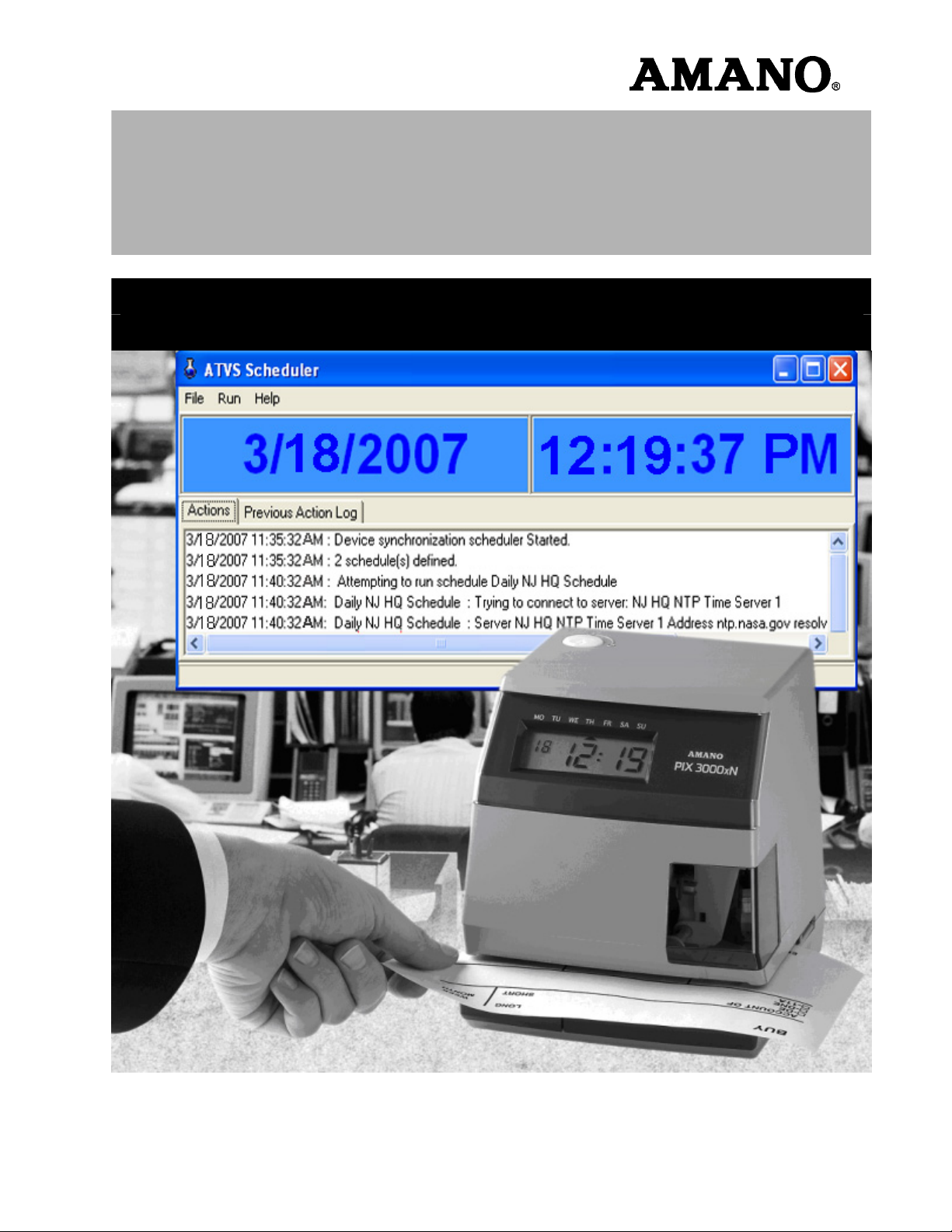
Chapter 3: ATVS Scheduler Operation ..................................................................................3-1
Actions Log.............................................................................................................................................3-1
Previous Action Log ...............................................................................................................................3-4
Exiting The Program ..............................................................................................................................3-4
ATVS Enterprise Edition v4.2 Installation & Operation Guide i
Page 4

Chapter 4: DeviceInstaller Use ...............................................................................................4-1
Importing Device IP/MAC Address.........................................................................................................4-1
Moving a Device to Another Group........................................................................................................4-5
Chapter 5: ATVS Reports ........................................................................................................5-1
How To Create a Report ........................................................................................................................5-1
How To Run a Report ............................................................................................................................5-5
How To Print a Report............................................................................................................................5-5
How To Create a Report File .................................................................................................................5-6
How To Delete a Report Profile .............................................................................................................5-7
How To Modify a Report Profile .............................................................................................................5-7
How To Navigate a Report.....................................................................................................................5-7
Device Report.........................................................................................................................................5-7
Schedule Report.....................................................................................................................................5-8
Time Server Report................................................................................................................................5-9
Transaction Report.................................................................................................................................5-9
Status Report .......................................................................................................................................5-10
Chapter 6: Action Log Messages ...........................................................................................6-1
Startup and Shut Down Messages.........................................................................................................6-1
Network Time Synchronization Messages.............................................................................................6-1
NIST ACTS Messages ...........................................................................................................................6-3
PIX Transmission Messages..................................................................................................................6-3
General and Other Messages ................................................................................................................6-4
Troubleshooting......................................................................................................................................6-5
ii ATVS Enterprise Edition v4.2 Installation & Operation Guide
Page 5

Chapter 1: Introduction and Installation
The ATVS application is available in 2 different versions:
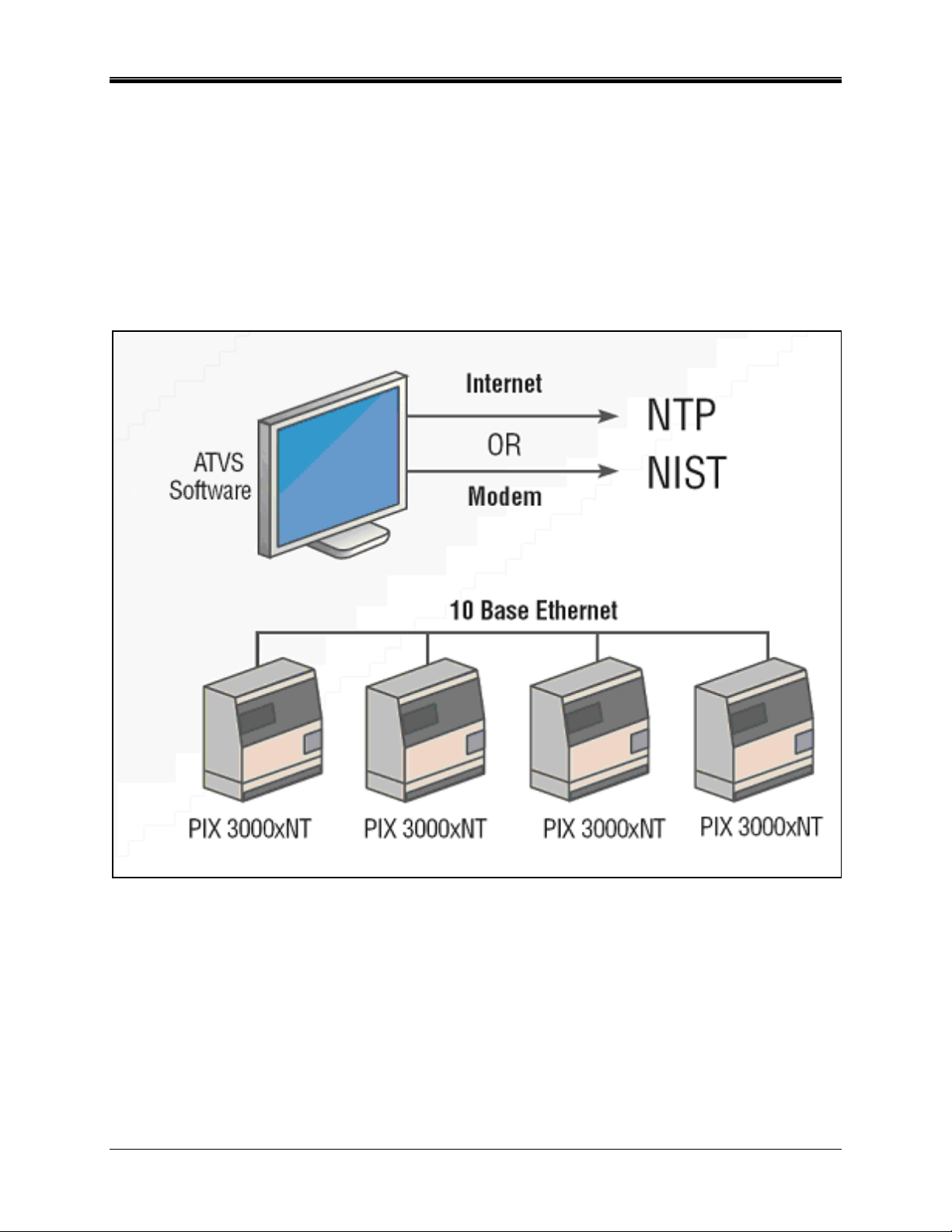
• An enterprise edition to provide the TCP/IP solution
solution. It does not simply attach to a network workstation, as with other so called TCP/IP
solutions. Each PIX-3000xNT time stamp has an internal NIC and is given an IP address for
synchronization over your network. The enterprise ATVS Software is installed on a server on
your network. The PIX-3000xNT time stamps are then deployed anywhere on your network.
Each time stamp requires an active available network port set to Base 10 communication
speed, with network connectivity back to the single ATVS Software installation. Also works
with PIX-3000xN time stamps, and the PIX-3000xN and PIX-3000xNT can co-exist on the
same server.
• A standard edition for a serial broadcast solution
Software installed on your own server as the host, but using the PIX-3000xN time stamps
(note: also works with PIX-3000xNT). Instead of transmitting the signal to each clock over
your network via TCP/IP, the signal is transmitted via the 9-pin serial port of the single
server. This in turn would attach to provided line drivers and patch panels to the office
cabling infrastructure going out to the clocks at the facility. The end-user can utilize standard
CAT5 or better grade, straight cable—no special wiring required. The PIX-3000xN and PIX3000xNT can co-exist on the same server.
This manual [AJR-40120X] covers only the Enterprise Edition, while Amano ATVS Standard
Edition Manual [AJR-40110X] discusses the standard version of the ATVS software.
for a “true” Ethernet time stamp
utilizing the same ATVS Configuration
How This Manual is Organized
The installation, configuration, and operation procedures in this manual are provided for user
assistance.
Chapter 1 provides a brief overview of features, benefits, and system components. Also
described is the general installation and configuration (using the Initial Wizard) guidelines. In
most instances, configuration should only need to be completed once.
Chapter 2 provides step-by-step procedures for general operation of ATVS. Also, this chapter
details how to use the Setup Wizard for additions/deletions to configuration performed with the
Initial Wizard during installation.
Chapter 3 provides a user's guide to the operation of ATVS Scheduler.
Chapter 4 provides a user's guide to the operation of DeviceInstaller.
Chapter 5 explains how to define, modify and run Report Profiles in ATVS.
Chapter 6 contains a complete list of Action Log Messages and basic troubleshooting
information.
Introduction – What is ATVS?
The Amano Time Validation System (ATVS) time synchronization software works in conjunction
with one or more devices (PIX-3000xN or PIX-3000xNT Time Recorders). The software and
time clock combination may communicate by way of TCP/IP or Serial RS485 connection.
The PIX-3000-series time clocks communicate according to these protocols:
• PIX-3000xN clocks with Serial RS485 direct connection
ATVS Enterprise Edition v4.2 Installation & Operation Guide 1-1
Page 6

• PIX-3000xNT clocks via Ethernet TCP/IP network connection
ATVS software runs on a Windows NT® 4.0 (or later) platform. This enables the use of standard
network management software and backup procedures to manage, maintain, and monitor the
software host.
The devices connected to the ATVS Host Server are synchronized by having the ATVS
synchronized to NIST's NTP (Network Time Protocol) server in Boulder, Colorado, or another
preprogrammed NTP source via the Internet. Once the ATVS Host Server has synchronized
itself, the correct time is then transmitted to all the devices.
What is OATS Compliance?
The Amano PIX-3000xN and PIX-3000xNT, used in conjunction with ATVS software, have been
specially designed by Amano in compliance with the Order Audit Trail System (OATS) rule
6953, Synchronization of Member Business Clocks.
Following is the OATS NASD rule:
Rule 6953 requires any NASD member firm that records order, transaction or related data
required under the By-Laws and Rules of the Association to synchronize all business clocks used
to record the date and time of any market event. Clocks, including computer system clocks and
manual time stamp machines, must record time in hours, minutes and seconds with to-thesecond granularity and must be synchronized to a source that is synchronized to within three
seconds of the National Institute of Standards’ (NIST) atomic clock. Clocks must be synchronized
once a day prior to the opening of the market, and remain in synch throughout the day. In
addition, firms are to maintain a copy of their clock synchronization procedures on-site. Clocks
not used to record the date and time of market events need not be synchronized.
Note: The above rule is similar to NYSE Rule 132A, to which this application and associated hardware
is also compliant.
ATVS Software Features
• Automatic time synchronization to an official time source.
• Event notification through SNMP (Simple Network Management Protocol) traps. This feature
enables network administrators to manage time clock performance, find problems, and solve
them in a timely manner.
• Amano has registered a unique SNMP identifier, which validates the SNMP trap feature.
• Multiple communications options to time validation units.
• NTP (Network Time Protocol) syncs clocks to a time reference over a data network.
• NIST (National Institute of Standards & Technology) synchronization available via modem.
• Direct synchronization to the time source rather than to a computer.
• Log-in security with configurable rights to sections of application.
• Software supports two communication options and validation units:
- PIX-3000xN clocks with Serial RS485 direct connection.
- PIX-3000xNT clocks via Ethernet TCP/IP network connection.
• Synchronization logging data maintained per Order Audit Trail System (OATS) Rule 6953
requirements.
• Full OATS compliance with stand-alone units not linked to a PC.
• Complete server-based solution, not on individual trader computers.
1-2 ATVS Enterprise Edition v4.2 Installation & Operation Guide
Page 7

• Reports including status/error, transaction log, and configuration settings.
• Unlimited syncs per day for improved accuracy.
• Compatible with Windows NT/98/2000/ME/2003/XP/Vista.
• Employs Windows Services to perform synchronization.
• E-mail notification of clock status and/or failure to synchronize time, configurable to select
group/device and send e-mail to chosen recipients.
ATVS Benefits
• Assures financial institutions’ compliance with OATS Rule 6953 as per NASD/SEC.
• Amano time stamp will continue to function and maintain time as a stand-alone unit, even if
it does not receive synchronization from the provided ATVS host software.
• The PIX-3000 series is the highest quality OATS-compliant time stamp available.
• Log files maintained automatically on hard drive of computer to which the software is
installed. Logs may be e-mailed, saved or printed as desired.
• Convenient system support provided by visible alarms on time stamp imprint and LCD
display should synchronization not occur.
• Provides a solution for industry sectors that require strict adherence to good time keeping
practices.
ATVS Typical User/Market
The following list is comprised of typical users/markets for Amano ATVS:
• Banks • Manufacturing
• Investment Brokers • Healthcare
• NASDAQ traders • Emergency Call Centers
PIX-3000xN & PIX-3000xNT Hardware Features
• Maintain time within four tenths of a second over a 24-hour period once synchronized.
• Time imprint format includes seconds as per OATS 6953 requirements.
• Prints through up to 6 multiple-part carbonless copies.
• Capable of printing the alphanumeric identification.
• Full power reserve permits clock operation in the event of power outage.
• Quick and easy ribbon cartridge replacement.
• Direct-connect or Ethernet time validation units.
ATVS Requirements
ATVS Time Synchronization software (Enterprise version) for Windows may be used in
conjunction with PIX-3000xN Time Recorders or PIX-3000xNT Time Recorders.
The ATVS software may be loaded on any PC and/or server operating under Windows NT or
later.
ATVS Enterprise Edition v4.2 Installation & Operation Guide 1-3
Page 8
ATVS General Information
During the installation process, both the ATVS application and ATVS Scheduler application use
the Setup.exe file and the same supporting files.
The installation procedure provides simple instructions on each screen. It is important to follow
these instructions carefully in the order for the ATVS Enterprise Edition to run correctly.
End-users may never need to change the configuration settings created thru the wizard at a
later time after the initial configuration setup. However, it is recommended that all configuration
settings should be recorded in the event that the setup needs to be repeated in the future.
While the Enterprise Edition of ATVS is running, the ATVS Scheduler runs as a service.
Figure 1. Enterprise Edition ATVS Diagram
1-4 ATVS Enterprise Edition v4.2 Installation & Operation Guide
Page 9
ATVS Installation Guide
ATVS Initial Software Installation
1. Turn on the computer for the ATVS application to be loaded.
2. Verify that no additional applications are running.
3. Insert the ATVS disk in the CD-ROM drive.
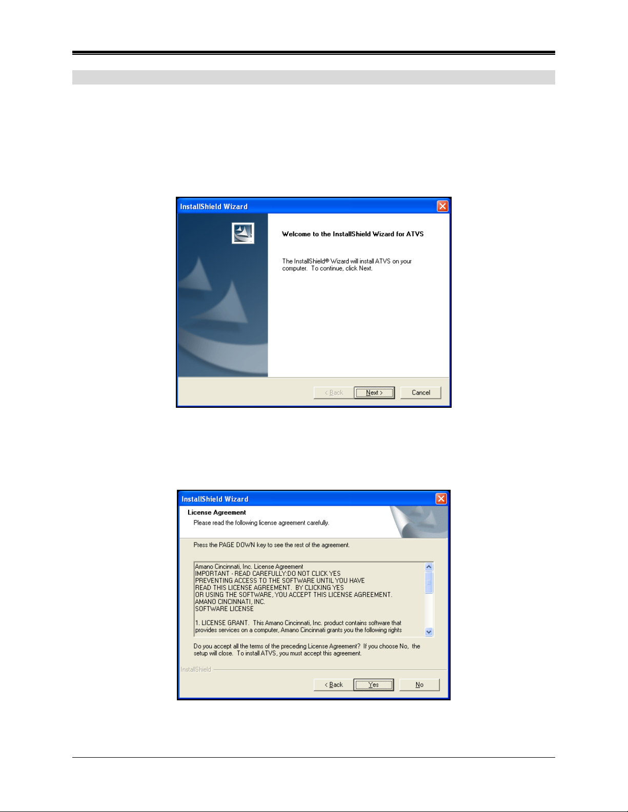
4. The InstallShield Wizard screen for ATVS will appear as shown in Figure 2.
Figure 2. InstallShield Wizard
5. Click Next to continue the installation, and the Software License Agreement will appear to
advise users of their legal responsibilities (see Figure 3). To continue the installation you
must click Yes to accept this agreement.
Figure 3. InstallShield Wizard License Agreement
ATVS Enterprise Edition v4.2 Installation & Operation Guide 1-5
Page 10
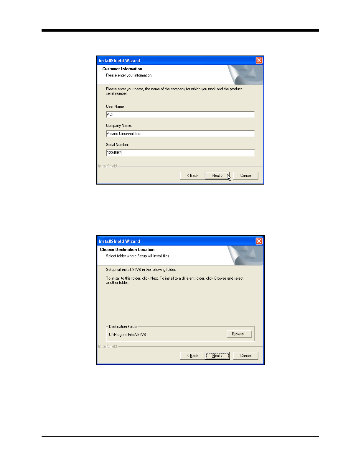
6. The following Customer Information screen will appear (see Figure 4). The ATVS serial
number should be on the CD.
Figure 4. InstallShield Wizard Customer Information
7. Enter the User Name, Company Name, and ATVS serial number. Then click Next to
continue with the setup, and the Destination Location screen will appear as shown in
Figure 5.
Figure 5. InstallShield Wizard Choose Destination Location
1-6 ATVS Enterprise Edition v4.2 Installation & Operation Guide
Page 11
8. When asked to Choose Destination Location, use the suggested Destination Folder (ATVS).
If the drive is not applicable to your system, click the Browse button to select a drive. Then
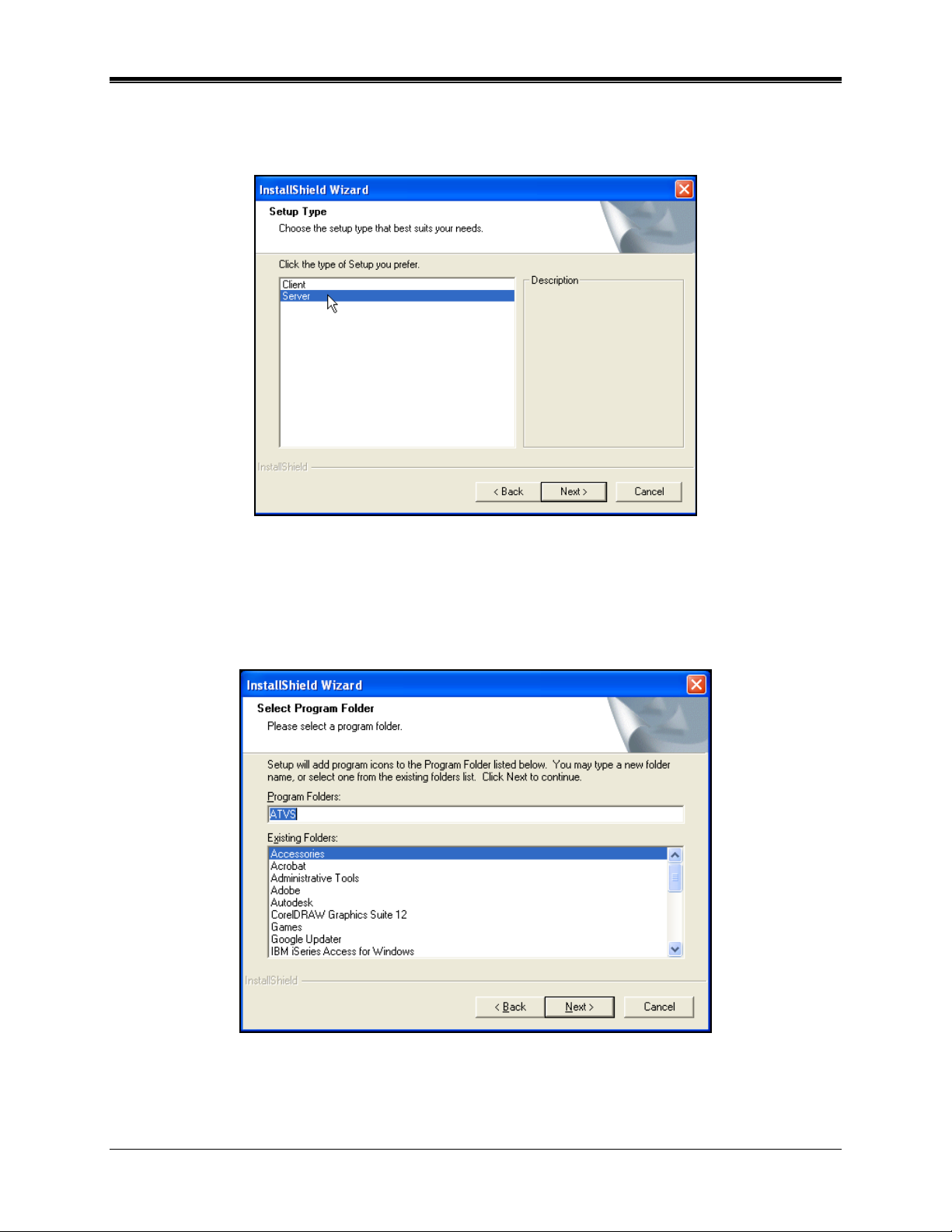
click Next to continue, and the Setup Type screen will appear (see Figure 6).
Figure 6. InstallShield Wizard Setup Type
9. When asked to choose the type of setup, it is recommended to click on Server. If the PC
you are loading ATVS on is connected to the ATVS system, you may want to click on Client.
Then click Next to continue, and the Select Program Folder screen will appear (see
Figure 7).
Figure 7. InstallShield Wizard Select Program Folder
ATVS Enterprise Edition v4.2 Installation & Operation Guide 1-7
Page 12
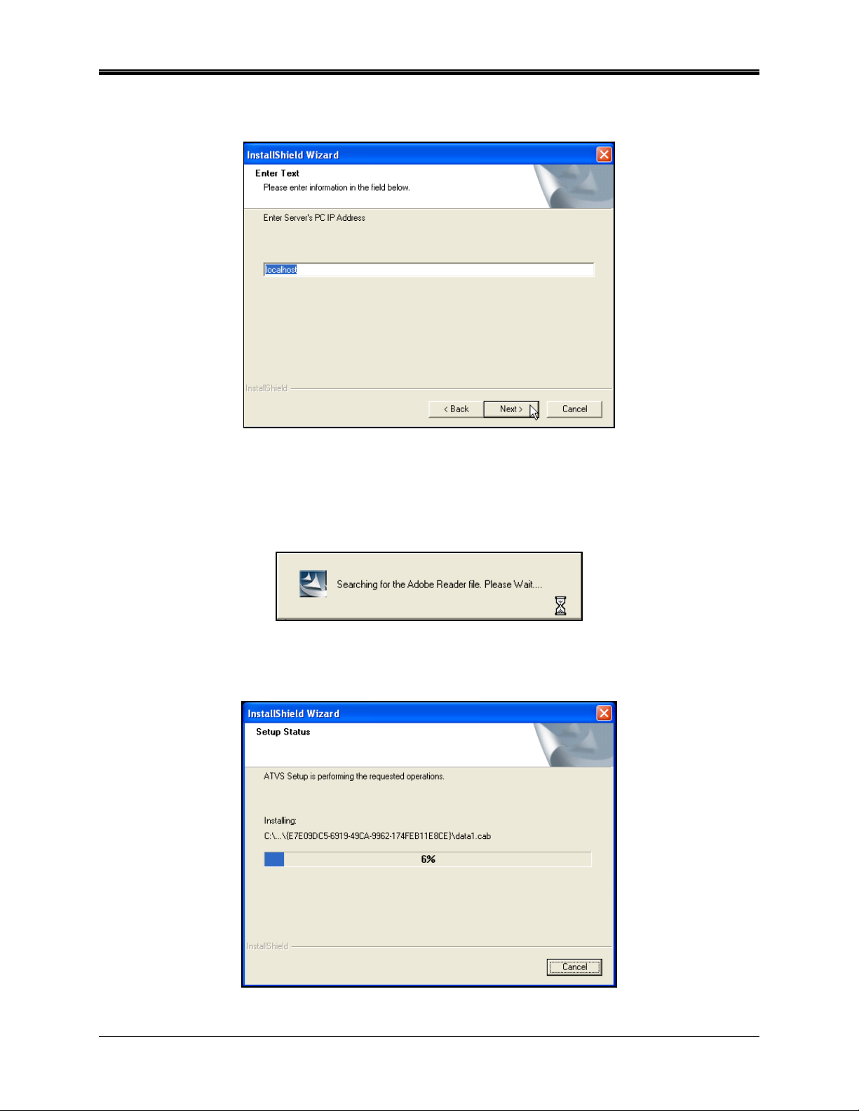
10. When asked to enter a server's (PC) IP Address, use the suggested localhost, and click
Next to continue (see Figure 8).
Figure 8. InstallShield Wizard Enter Text
11. During installation, the installation will check for the presence of the Adobe Acrobat Reader,
necessary for the display of PDF-formatted reports. If no Reader is present, that application
will install. During that process, the following screen will briefly appear:
12. Next a Setup Status screen will appear showing a progress status bar for the ATVS
installation as shown in Figure 9.
Figure 9. InstallShield Wizard Setup Status
1-8 ATVS Enterprise Edition v4.2 Installation & Operation Guide
Page 13
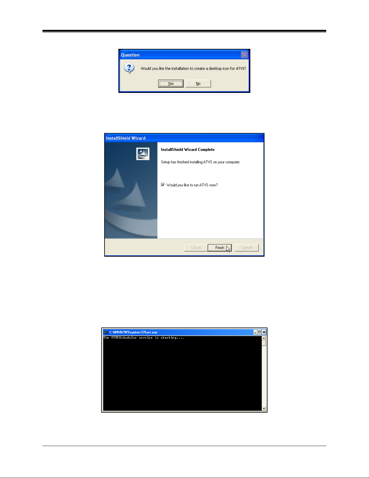
13. During installation, if desired, click Yes to create a desktop icon for ATVS (see Figure 10).
Figure 10. Desktop Icon Dialog
14. The InstallShield Wizard Complete will appear (see Figure 11) when done.
Figure 11. InstallShield Wizard Complete
15. Click on Finish, and if the box "Would you like to run ATVS now?" is checked, the program
will immediately start, and the following screen will appear signifying the ATVS Scheduler
service is starting (see Figure 12).
Note: See the next section, "ATVS Software Activation, which should normally be performed
immediately following the ATVS software installation.
Figure 12. ATVS Scheduler Service Starting
ATVS Enterprise Edition v4.2 Installation & Operation Guide 1-9
Page 14
ATVS Software Activation
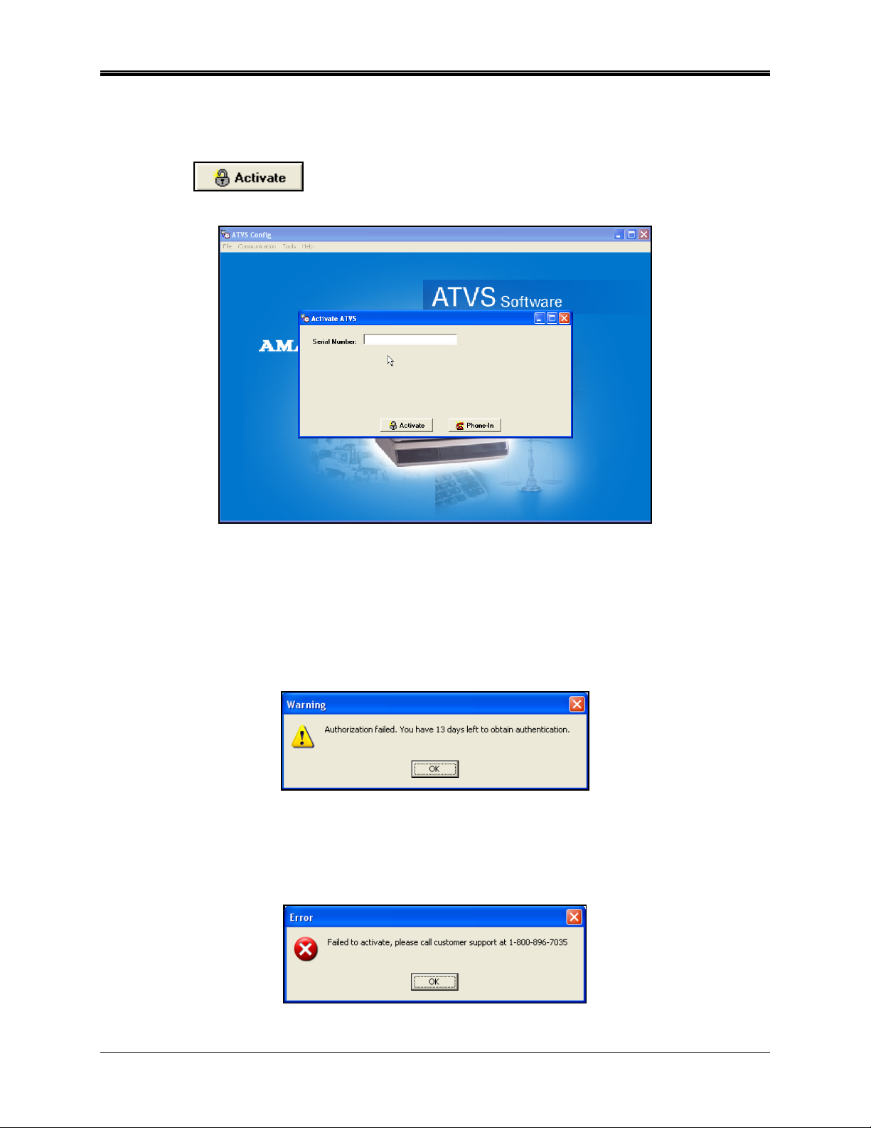
1. Figure 13 displays the Activate screen which appears the first time the program is started up
after initial installation. Enter the serial number supplied with the software and click on the
Activate
button. If activation is successful the "Activation was successful.
Would you like to register?" screen will appear (skip to step 4).
Figure 13. Activate ATVS
If you choose not to Activate the software at this point by canceling the activation the
following error message will appear (see Figure 14). At this point you have a trial period of
up to 14-days to use the ATVS software. During this period you must successfully activate
the software. Click on the OK button to launch the ATVS program and display the Initial
Wizard screen (from this step proceed to step 1 of the ATVS Initial Configuration, page
1-12).
Figure 14. ATVS Authorization Failed
2. If an Activation error dialog message appears (see Figure 15), the serial number is incorrect,
no Internet connection with the Amano authorization server occurred, or the same serial
number has previously been installed.
Figure 15. Failed to Activate Customer Support Required
1-10 ATVS Enterprise Edition v4.2 Installation & Operation Guide
Page 15
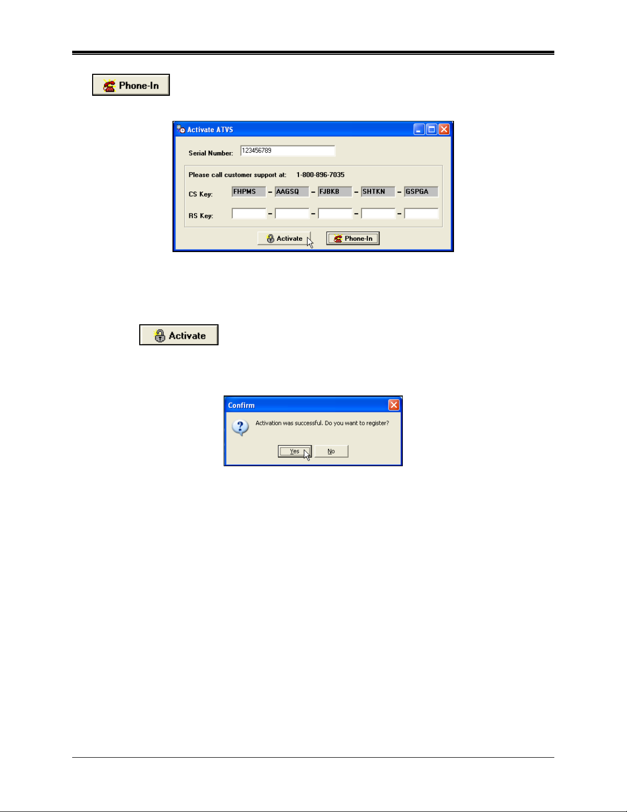
3. If the serial number is valid, but customer support is desired click on the Phone In
button from the Activate screen and the Activate ATVS screen for customer
support will appear (see Figure 16).
Figure 16. Activate ATVS with Customer Support
Call Amano support at 1-800-896-7035 and the support personnel will ask for the CS Key
code letters displayed on your screen (see Figure 16). Enter the supplied [from Amano
support] RS Key code into the appropriate fields in five character increments. Click on the
Activate
button to activate and launch the ATVS program.
4. Upon successful authorization the following screen will appear (see Figure 17). Click Yes to
register.
Figure 17. Confirm ATVS Activation
Alternately, the registration can be skipped by clicking the No button. However, it is
suggested at this time to register the new customer, but a customer can always register by
clicking on the File menu and pulling down to Register to open the Register screen (see the
following figure).
Note: You cannot register the software until the activation process is complete.
5. Enter the appropriate information in the registry fields (see Figure 18). The minimum
information required to successfully register is; Last Name, First Name, City, and Type [Red
outlined fields]. Select the type from the dropdown menu, and click OK to register and
launch the ATVS program to display the Initial Wizard (see Figure 19).
ATVS Enterprise Edition v4.2 Installation & Operation Guide 1-11
Page 16
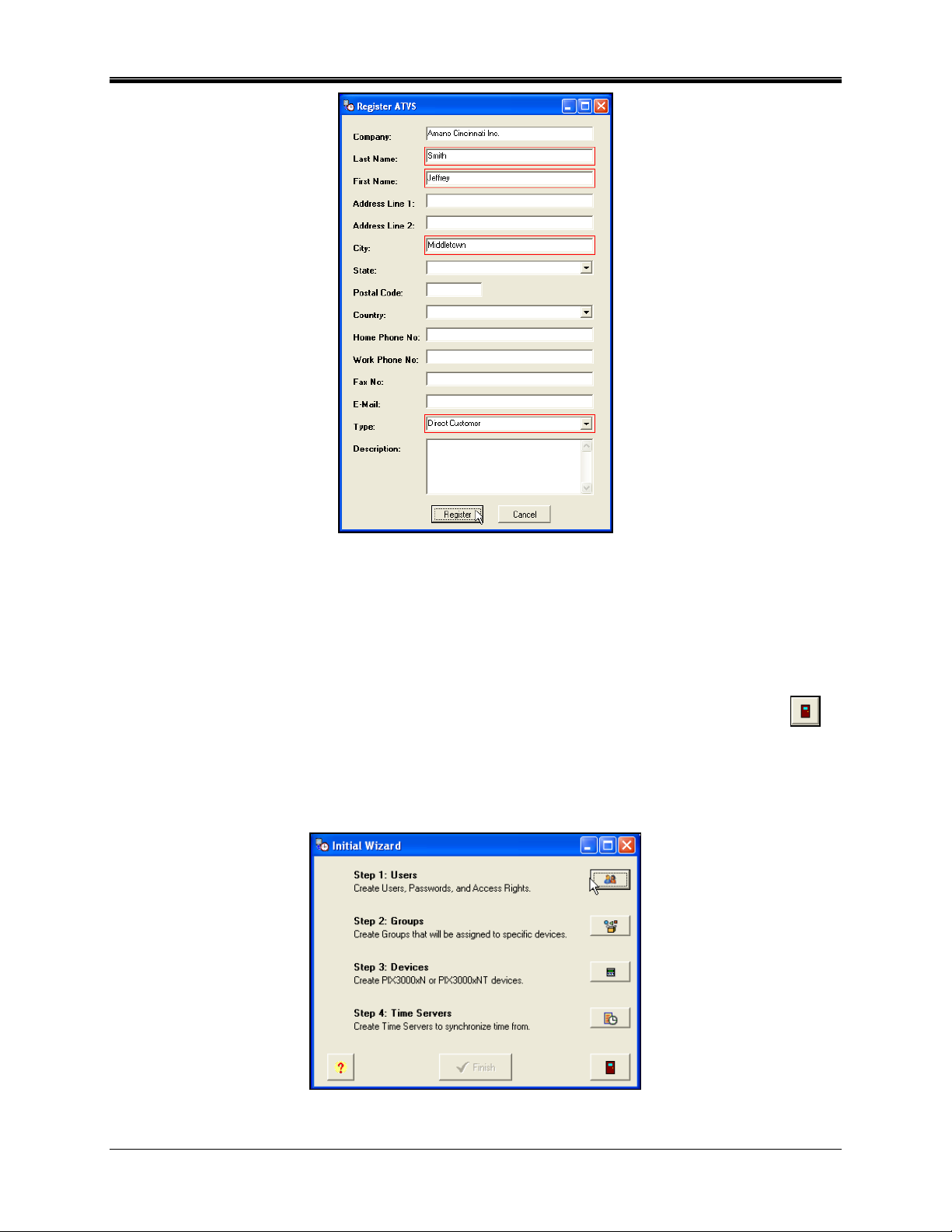
Figure 18. ATVS Registration
Click on the Cancel button to abort the registration process and perform at a later time. The
ATVS Initial Wizard screen should now appear (see Figure 19).
ATVS Initial Configuration
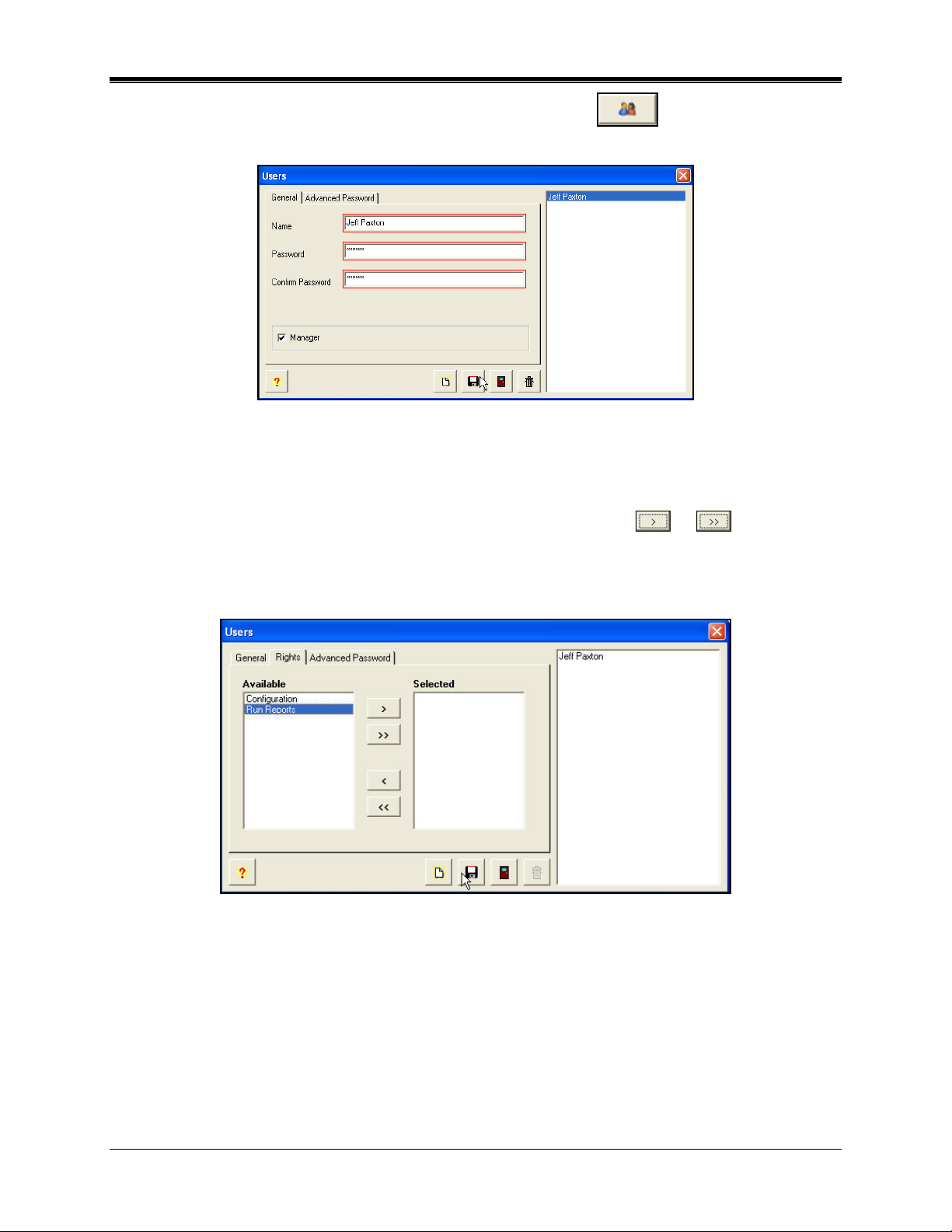
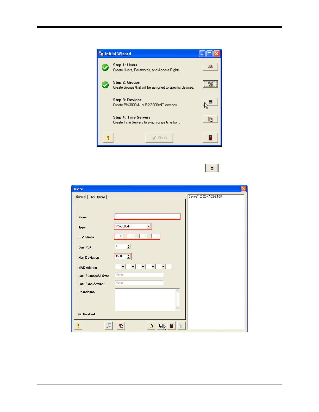
1. After the ATVS Scheduler and program has started the Initial Wizard screen will appear. All
4 steps must be completed to finish the initial configuration and installation. If the Exit
button is pressed before completion a warning confirmation dialog will appear. The next time
ATVS is started the Initial Wizard screen will pickup with the last completed step. It is
suggested to complete all the steps, and in numerical order.
Note: The green checkmarks indicate that a step is complete.
Figure 19. Initial Wizard
1-12 ATVS Enterprise Edition v4.2 Installation & Operation Guide
Page 17
2. For Step 1 from the Initial Wizard, click on the Create Users icon, and the Users
screen will appear (see Figure 20).
Figure 20. Users General Tab
3. Enter a Name, Password [6 character minimum], Confirm Password, and select a Language
from the dropdown menu. Note that user names and password are case-sensitive. If
Manager is not checked, click on the Rights tab to select the rights (see Figure 21). From
the Available list, select the Rights by using the selection arrows (
or ) to move
them to the Selected list on the right.
Note: If Manager is checked, then the "Rights" tab will not appear as all rights will
automatically be assigned to this user.
Figure 21. Users Rights Tab
4. Click on the Advanced Password tab to select expiration (see Figure 22). The default is
Never Expire, so this screen can be skipped if the default selection is acceptable. From the
three choices, select one of the following: Never Expire, Expires after, or Expires On.
ATVS Enterprise Edition v4.2 Installation & Operation Guide 1-13
Page 18
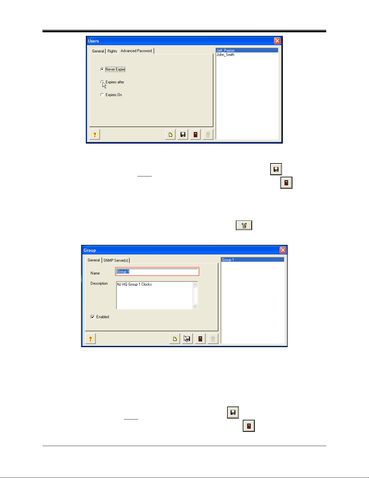
Figure 22. Users Advanced Password Tab
5. When finished with entering each new user in this step, click on the Save button to
save the user settings. When finished creating new users, click on the Close
button to
return to the Initial Wizard screen.
6. Step 1 is now complete, and the Initial Wizard screen will indicate this with a green
checkmark.
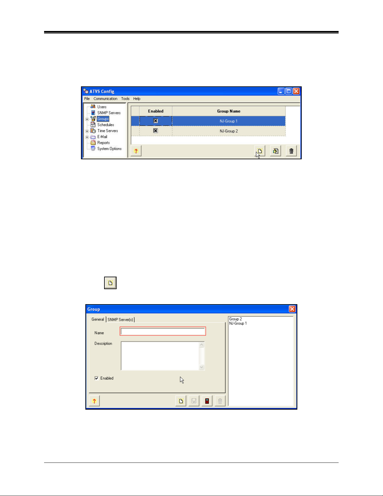
7. For Step 2 from the Initial Wizard, click on the Create Groups
icon, and the Group
screen will appear (see Figure 23).
Figure 23. Create Groups General Tab
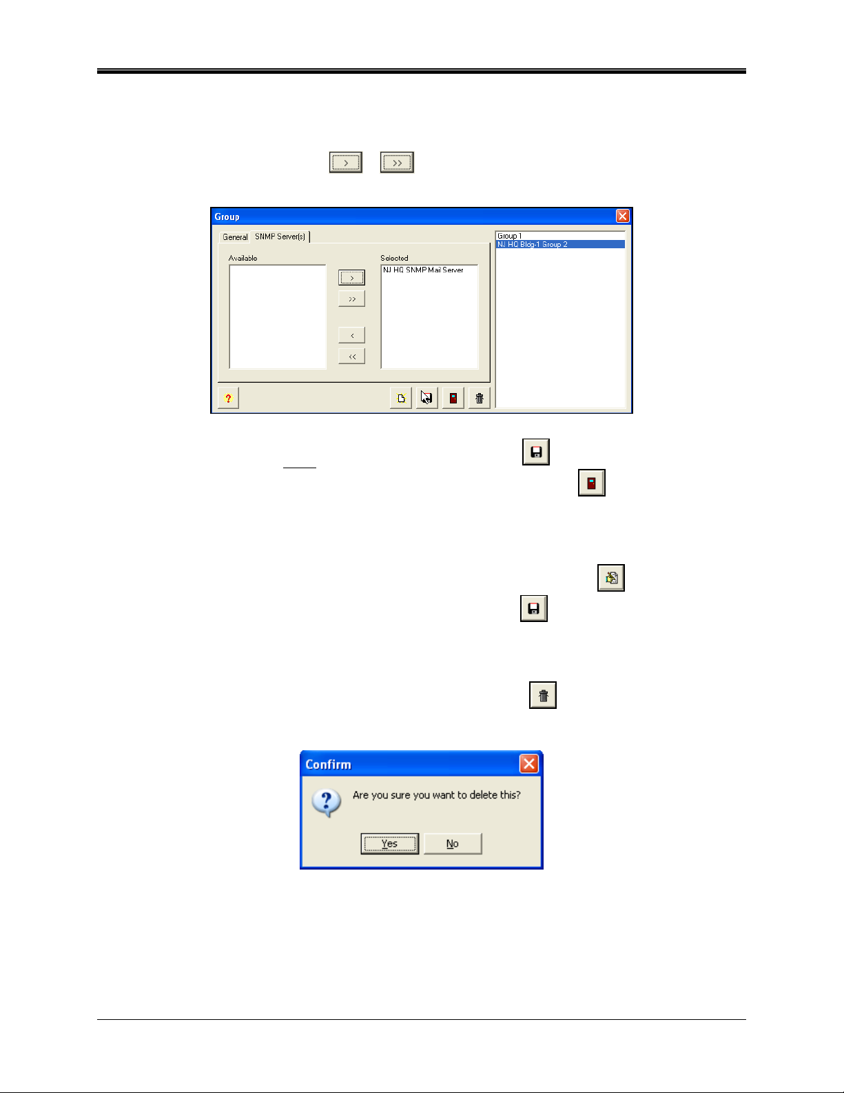
8. Enter a Name and Description. The SNMP Server(s) tab should not be used at this
moment. See page 2-5 for more information about setting up SNMP Servers for SNMP
traps.
Note: If "Enabled" is checked, then all defined Groups will be active.
9. When finished entering each new group, click on the Save button to save the group
settings. When finished creating new groups, click on the Close
button to quit, and
return to the Initial Wizard screen.
1-14 ATVS Enterprise Edition v4.2 Installation & Operation Guide
Page 19
10. Step 2 is now complete, and the Initial Wizard screen will indicate this with a green
checkmark (see Figure 24).
Figure 24. Initial Wizard Step 2 Complete
11. For Step 3 from the Initial Wizard, click on the Create Devices icon, and the Device
screen will appear (see Figure 25).
Figure 25. Create Devices General Tab
12. Select the Group from the dropdown menu, and enter the Name. Select the device Type
from the dropdown menu (PIX-3000xN or PIX-3000xNT). Enter the IP Address if known
(PIX-3000xNT only).
ATVS Enterprise Edition v4.2 Installation & Operation Guide 1-15
Page 20
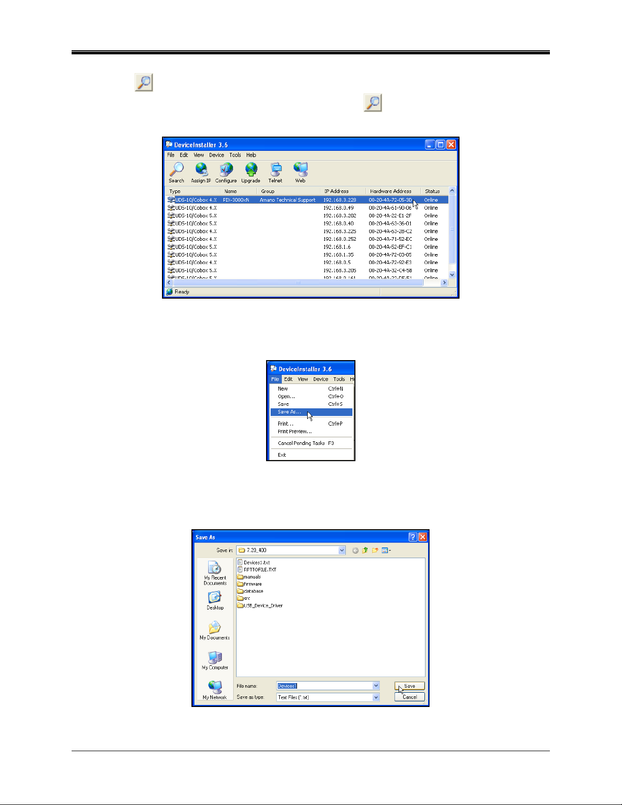
13. If the IP address/ MAC Address is unknown, from the Device screen, click on the Device
Lookup
14. From the DeviceInstaller, click on the Magnifying glass
button, and the DeviceInstaller will launch (for PIX-3000xNT lookup only).
to use the search tool to locate
the PIX-3000xNT IP/Mac addresses. shows an example of a search.
Figure 26. DeviceInstaller Search Results Example
15. Click on File and select the Save As sub-menu (see Figure 27).
Figure 27. DeviceInstaller File/Save As Menu
16. From the Save As dialog (see Figure 28), select a destination folder [Save in:] and enter a
file name. Click on the Save button and a text file with the IP search results will be saved.
Figure 28. Save As Dialog
1-16 ATVS Enterprise Edition v4.2 Installation & Operation Guide
Page 21
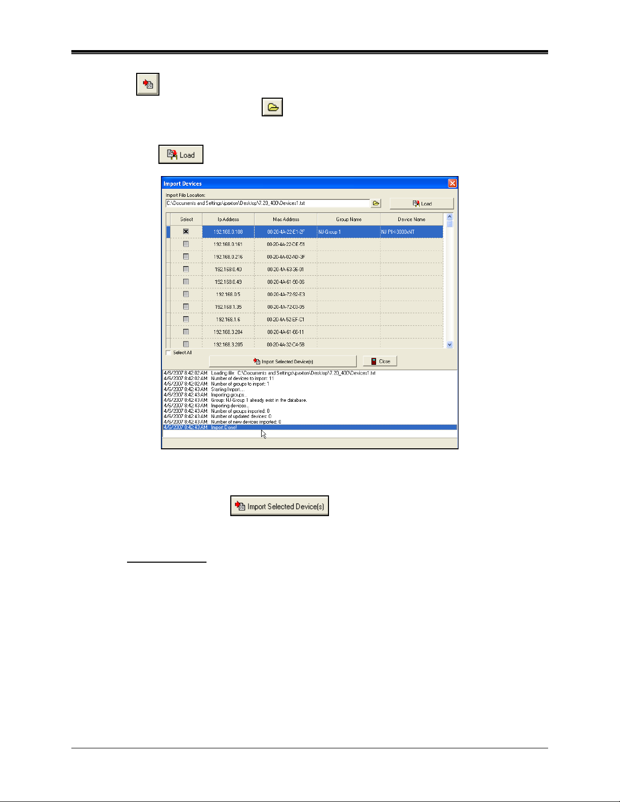
17. Close the DeviceInstaller, and from the ATVS Config Device screen click on the Import
Devices
Click on the Import File Location
button and the Import Devices screen will appear (see the following figure).
button and navigate to the saved Devices txt file
from the previous step. Once the file is selected, click on the Open button and the path for
the text file with the IP search results will appear in the "Import File Location" field. Click on
the Load File
button and the device information will appear on the screen (see ).
Figure 29. Import Devices Example
18. Select the desired device to import (load) by clicking in the "Select" box, and click the
Import Selected Device(s)
button and the dialog "Are you sure you
want to import these devices?" will appear. Click on Yes to import the device(s). The status
display on the bottom of the Import Devices screen will show the device import transaction.
Note: The Description field on the Device screen will be auto populated with the text; " This
device was created in the import module" when the Import Module is used to create the
device.
19. Click on the Other Options tab, and the screen will appear as shown in Figure 30. Either
use the local Time Zone, or select the appropriate time zone from the dropdown menu. The
Time Zone selected controls the specific Time Zone adjustment sent to the individual PIX3000 device currently being configured within your ATVS setup. The setup for each PIX3000 device allows for custom Time Zone configuration. Where OATS compliance is
necessary, verify that the Use Local PC Time Zone option is not checked. The Time Zone
must be set to Coordinated Universal Time (UTC) UTC-5:00 Eastern.
ATVS Enterprise Edition v4.2 Installation & Operation Guide 1-17
Page 22
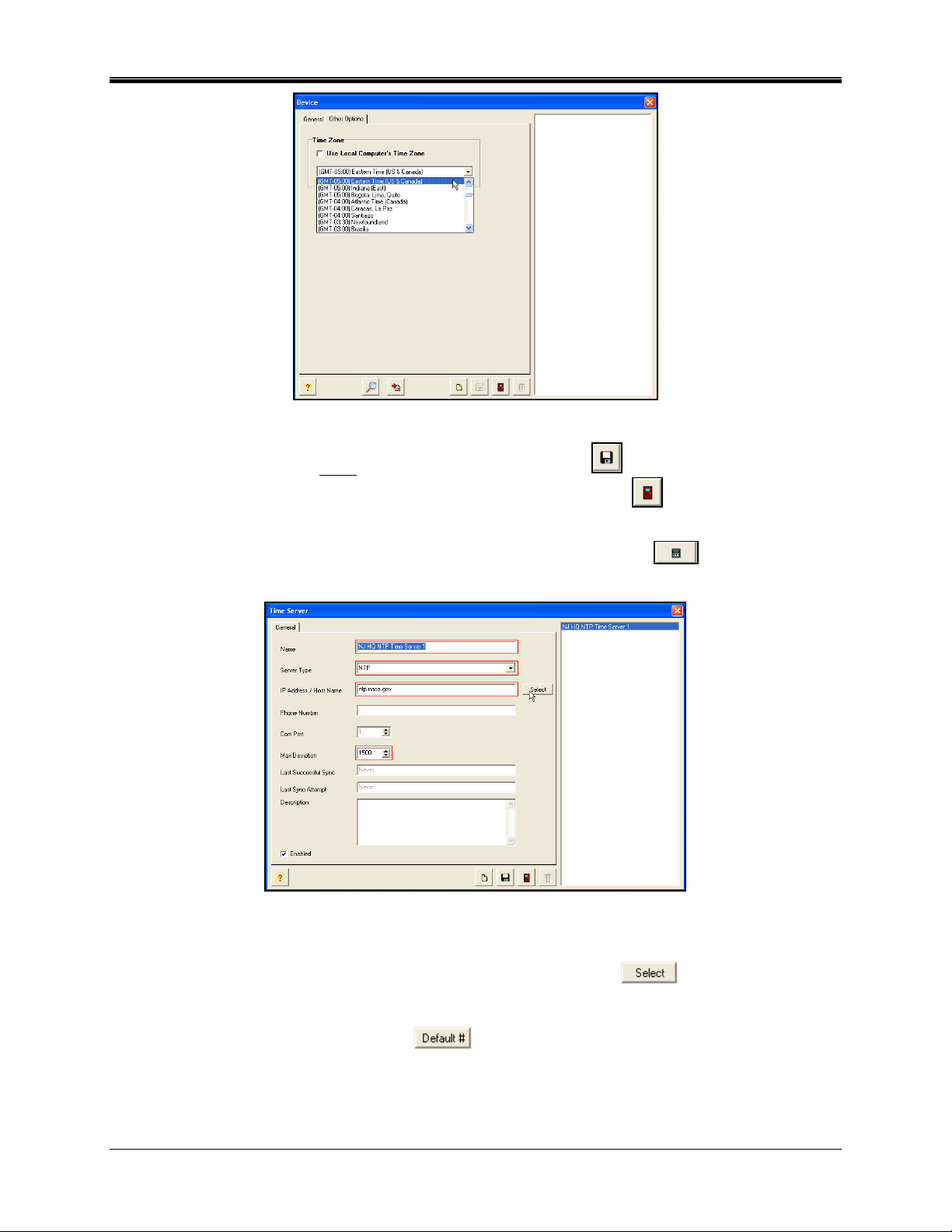
Figure 30. Create Device Other Options Tab
20. When finished entering each new device, click on the Save button to save the device
settings. When finished creating new devices, click on the Close
button to quit, and
return to the Initial Wizard screen.
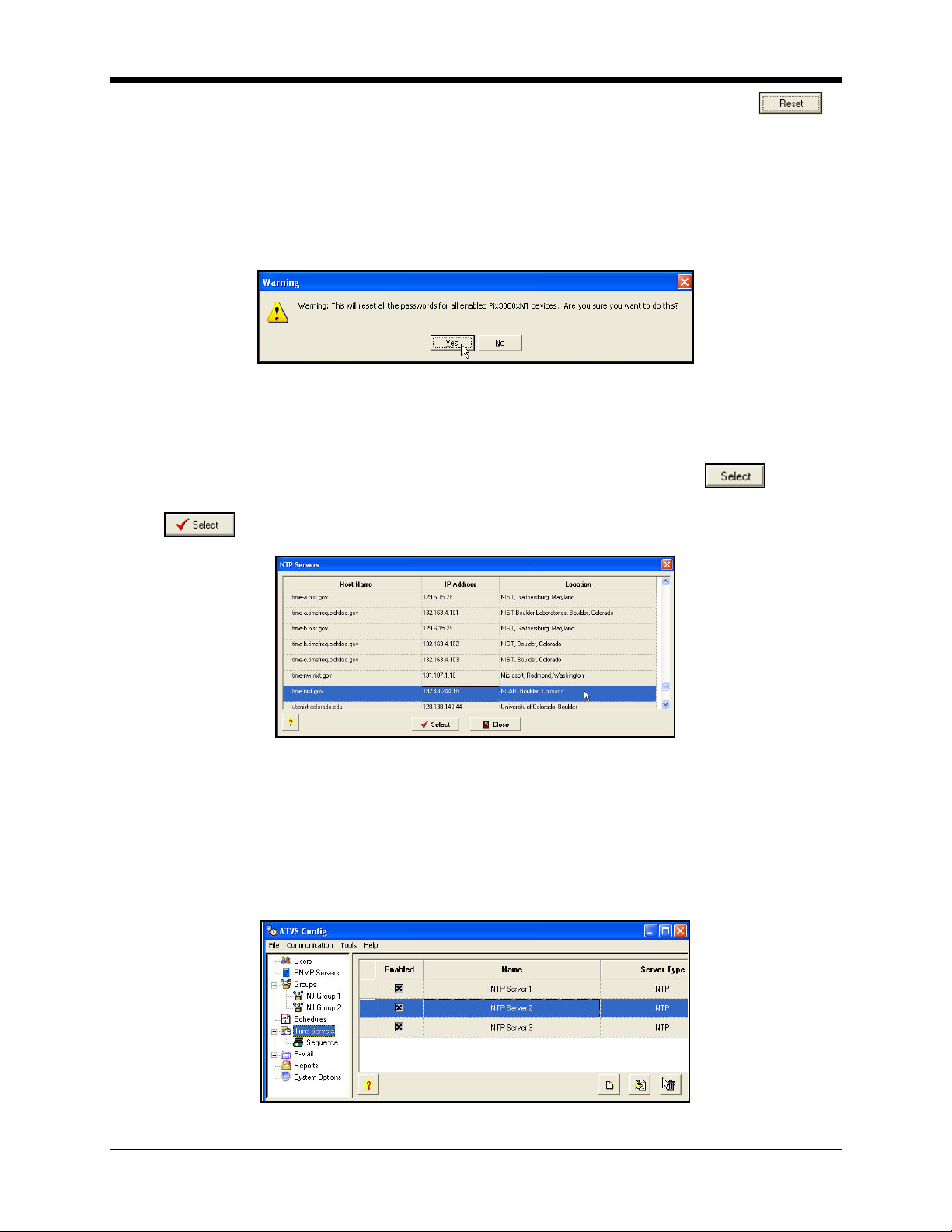
21. For Step 4 from the Initial Wizard, click on the Create Time Servers
icon, and the
Time Server screen will appear (see Figure 31).
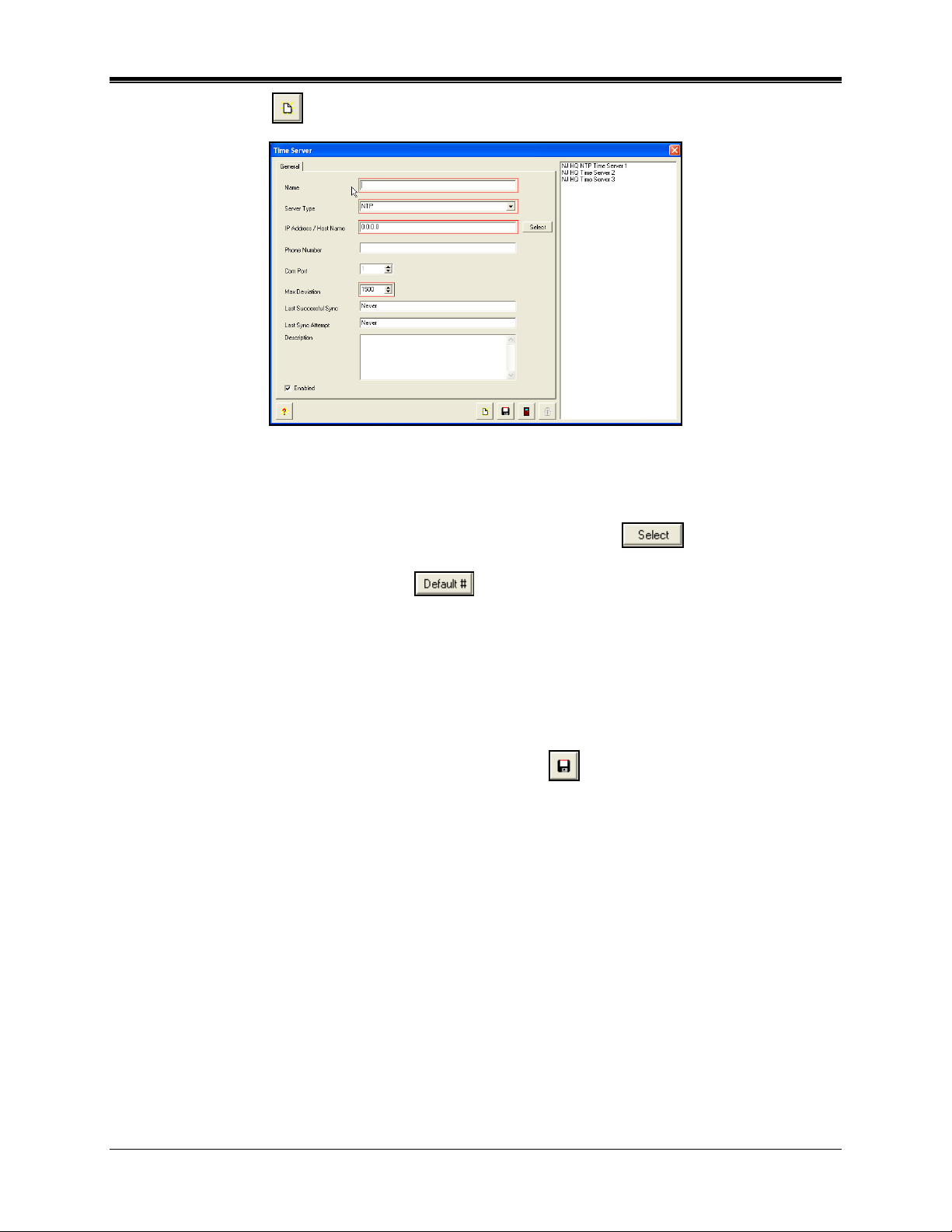
Figure 31. Create Time Server
22. Enter a Name, and select the server type from the dropdown. The server type choices are;
NTP, NIST (US), NPL (UK), or PTB (DE). For NTP, click on the
button and a list of
suggested NTP servers will appear to choose from (see ). See Chapter 6 for additional NTP
server information.
For NIST, NPL, or PTB, click on the
button and the default modem phone number
for the server will appear in the Phone Number field. Also, the Com Port field will be active to
enter the desired Com Port. (If employing NIST, NPL or PTB, a phone modem and phone
line are necessary.)
1-18 ATVS Enterprise Edition v4.2 Installation & Operation Guide
Page 23
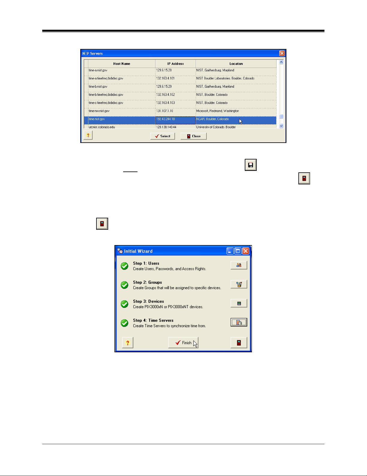
Enter the Max Deviation. The default is 1500 ms (1.5 seconds).
Figure 32. NTP Servers
23. When finished entering each new Time Server, click on the Save button to save the
Time Server settings. When finished creating new Time Servers, click on the Close
button to quit, and return to the Initial Wizard screen.
24. The Initial Wizard is now complete (see Figure 33). Click on the Finish button.
Note: The user can quit the initial wizard at any time during the step-by-step process by clicking
on the Exit
icon. However, all 4 steps must be completed with the minimum required
information before the installation process is complete.
Figure 33. Initial Wizard Complete
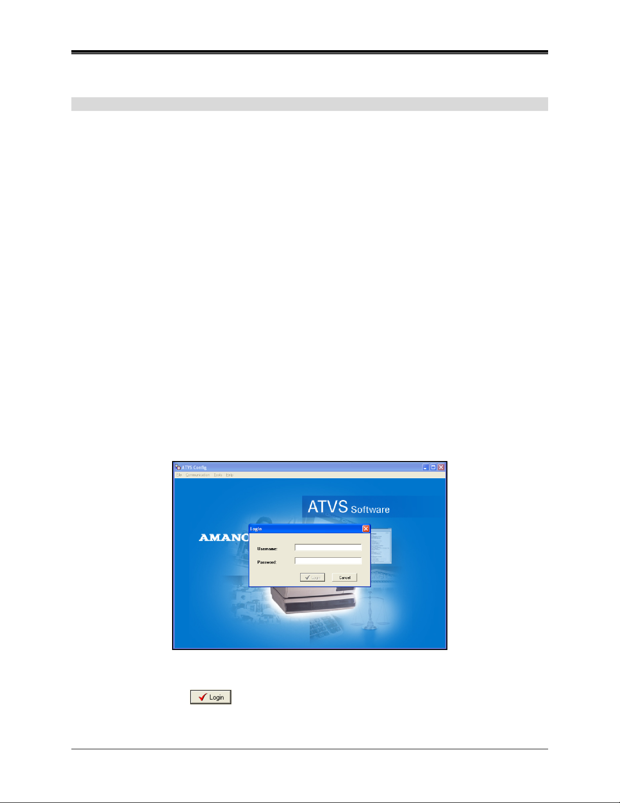
25. A user can now login, and he ATVS program will start with the Login (see Figure 34).
ATVS Enterprise Edition v4.2 Installation & Operation Guide 1-19
Page 24
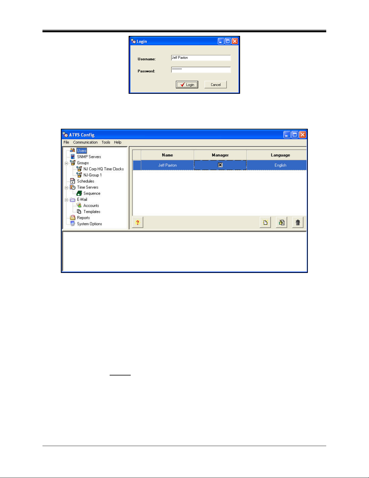
Figure 34. ATVS Login
26. Enter the correct Username and Password (previously defined in Step 3:Users on page 1-
13), and the ATVS Config main screen will appear (see Figure 35).
Figure 35. ATVS Config Main Screen
27. The ATVS software installation is now complete. Remove the installation disk from the CDROM drive.
Notes:
The ATVS Scheduler and ATVS Config programs will automatically start after the installation in
order for the configuration to be completed.
Refer to Chapter 2: ATVS Operation in order to set up the schedules, E-mail, Reports, and/or
System Options in the ATVS Config before using the program.
After installation, ATVS Scheduler will be added to the Windows Startup Menu, so that it will
automatically run as a service
whenever a user logs onto Windows.
1-20 ATVS Enterprise Edition v4.2 Installation & Operation Guide
Page 25
Chapter 2: ATVS Config Operation
General Information
After ATVS has been initially installed on a PC and the initial setup wizard completed, ATVS
Config will automatically start.
To configure the system, you must:
• Prepare synchronization schedules.
• Verify that the installed NIC’s (Network Interface Cards) in the ATVS system are recognized
by ATVS and configured properly.
• Define groups that reference the locations of the installed PIX-3000xN and/or PIX-3000xNT
Time Recorders (using the Wizard).
• Add and configure the devices (PIX-3000xN and/or PIX-3000xNT Time Recorders) that will
be used in each group (using the Wizard).
• Assign communication parameters (IP addresses and Com ports) to each PIX-3000xN
and/or PIX-3000xNT (using the Wizard).
• Assign the NTP servers that will be used to synchronize your ATVS host (using the Wizard).
• Choose the system settings, time zone, and Daylight Saving Time (DST) that are applicable
to your installation (using the Wizard).
Note: Users should be reminded that this configuration usually remains unchanged after
installation. Any questions can be directed to Amano's technical support.
ATVS Config Startup
At startup, ATVS will display the ATVS Startup and Login screen (see Figure 36).
Figure 36. ATVS Startup and Login
Enter the case-sensitive Username and Password (previously defined during the Initial Wizard),
then click on the Login
button, and the ATVS Config main screen will appear (see
Figure 37).
ATVS Enterprise Edition v4.2 Installation & Operation Guide 2-1
Page 26
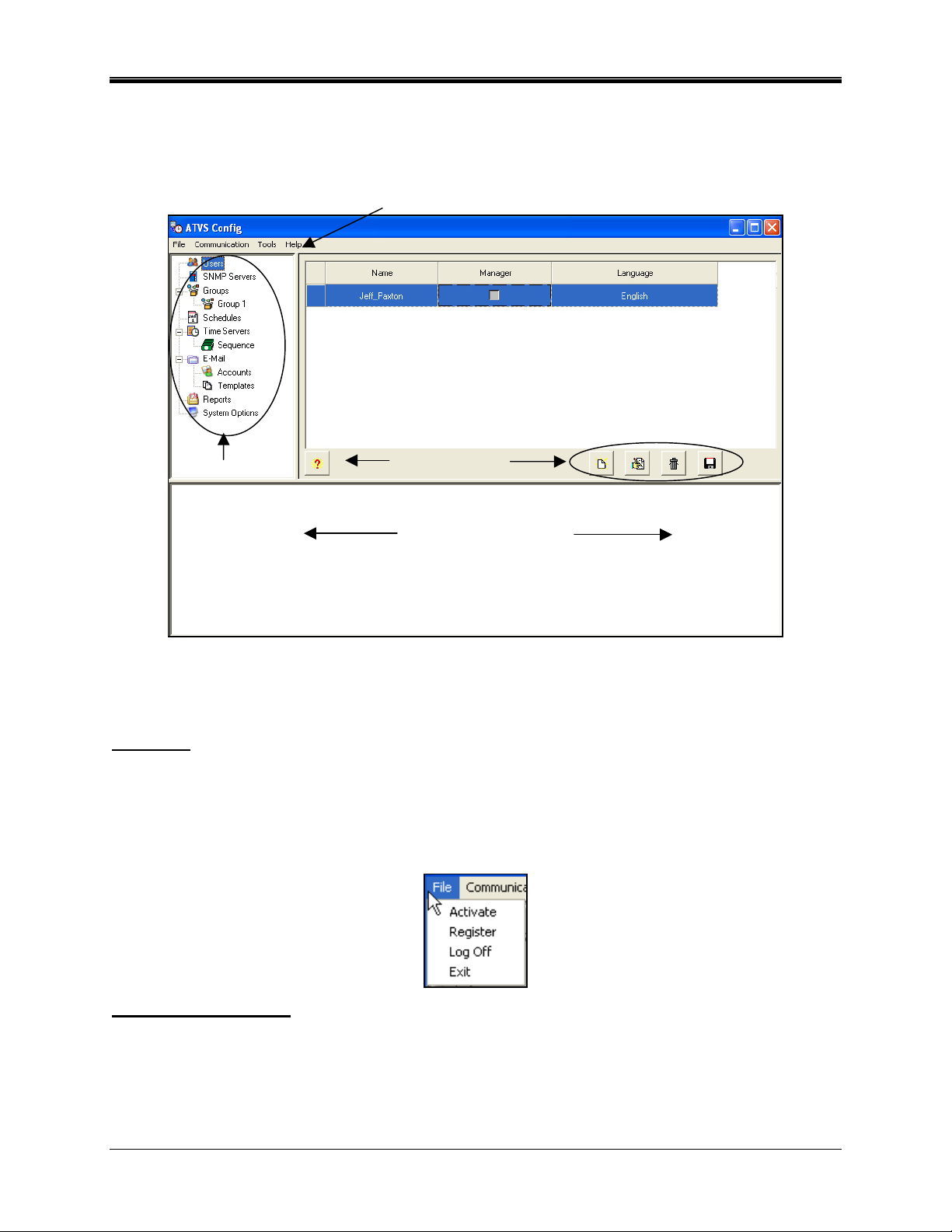
ATVS Config Layout
Figure 37 displays the default main view of ATVS Config screen and identifies its various
sections. This view can be changed based upon the selection made from the menu selections
and/or the tree view selections on the left-hand side of the screen.
Menu Selections
Tree View
Common Icons
Time Sync Log Viewer
Figure 37. ATVS Main Screen Layout
ATVS Config Main Dropdown Menus
File Menu
The File menu provides the following functions: The "Activate" selection allows entry of the
product serial number, necessary for continued operation of the software beyond the 14-day
trial period allowed during initial installation; "Register" allows you to register as a new ATVS
user, “Log Off” allows you to log off the program without quitting the application; Selecting "Exit"
quits the application.
Communication Menu
The Communication menu has two synchronization methods:
• Obtain Time Server time, and then sync devices
• Use the host PC’s time for synchronization, not employing any recognized Time Server
(generally, not the preferred method)
2-2 ATVS Enterprise Edition v4.2 Installation & Operation Guide
Page 27
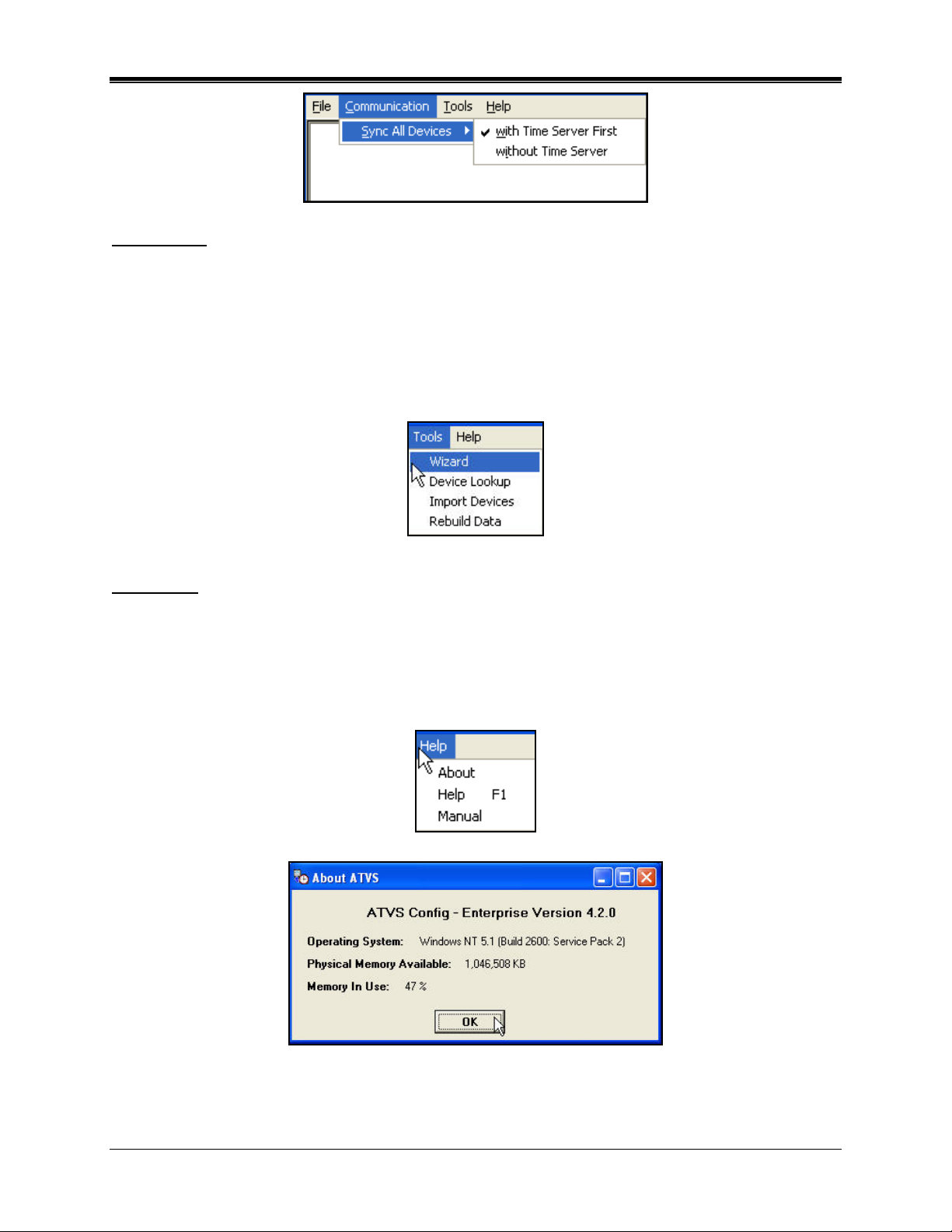
Tools Menu
The Tools menu allows you to configure the ATVS application by following a numbered step-bystep process using the "Setup Wizard".
The "Device Lookup" sub-menu selection will launch "DeviceInstaller", which can be used to
find and configure devices for ATVS communications.
The "Import Devices" sub-menu selection will launch the Import Devices screen allowing IP
addresses and/or MAC addresses to be loaded directly into the Device configuration (see
Wizard Step 1.3: Devices for more information).
Help Menu
The Help menu "About" selection (see Figure 38) will provide you with the current version of
ATVS that you are using. This information is required when placing a support call.
The "Help F1" selection provides online help.
The "Manual" selection will launch a PDF version of the ATVS Installation and Operation Guide
(AJR-40120X).
Figure 38. About ATVS
ATVS Enterprise Edition v4.2 Installation & Operation Guide 2-3
Page 28

Common Buttons
Certain common functions are performed using buttons. These buttons are shown below. In the
following table, the names shown in the description column explain the associated function.
Within the application, hovering the cursor over a button will display the tool tip description.
Button Description Button Description
Add
Close or Exit
Edit
Save
Print Report
Previous/Next Page
Zoom In/
Zoom Out
Help
Delete
Run Report
Device Lookup
Import Devices
Wizard Icons
Certain wizard functions are performed using icons. These icons are shown below. In the
following table, the names shown in the description column explain the associated function.
Hovering the cursor over an icon will display the tool tip description.
Icon Description Icon Description
Create Groups
Create Schedules
Create Devices
Create Time Servers
Create SNMP Servers
Create E-Mail Templates
Previous Step
Setup System Settings
Create Users
Create E-Mail Accounts
Create E-Mail Settings
Next Step
2-4 ATVS Enterprise Edition v4.2 Installation & Operation Guide
Page 29

Using the ATVS Config Setup Wizard
Step 1: Communication
1. From the ATVS Config screen, click on the Tools menu, and select the Wizard. The Setup
Wizard screen will appear (see Figure 39). It is recommended to configure ATVS in the step-
by-step order displayed in the Setup Wizard. The Setup Wizard will always start at Step 1:
Communication.
Figure 39. Setup Wizard Step 1
2. For Step 1.1, click on the Create SNMP Servers icon, and the SNMP Server screen
will appear (see Figure 40). Enter information into the required fields: Name, IP Address,
Port, and Community Name.
Figure 40. Create SNMP Server
Note: All fields outlined in Red should be completed.
3. When finished defining an SNMP Server, click on the Save button to save your SNMP
Server and return to the Setup Wizard screen. Click on the Close
button to quit without
saving. The new SNMP Server information will be displayed to the right of the tree view list.
4. For Step 1.2, click on the Create Groups
icon, and the Group screen will appear
(see Figure 41).
ATVS Enterprise Edition v4.2 Installation & Operation Guide 2-5
Page 30

Figure 41. Create Group General Tab
Note: All fields outlined in Red should be completed.
5. Enter information in the required Name field, and elective Description field. Click on the
Enabled box to enable all devices within the group. Then click on the SNMP Server(s) tab,
and the screen will appear as shown in Figure 42. Next assign SNMP Servers, from the
Available list (default status for SNMP Servers previously defined in Step 1.1), select the
SNMP Servers by using the selection arrows (
or ) to move them to the Selected
list on the right from the Available list on the left.
Figure 42. Group SNMP Servers Tab
6. When finished entering each new Group, click on the Save button to save the Group
settings. When finished creating all new groups, click on the Close
button to quit, and
return to the Setup Wizard screen.
7. For Step 1.3, click on the Create Devices
icon, and the Device screen will appear
(see Figure 43).
2-6 ATVS Enterprise Edition v4.2 Installation & Operation Guide
Page 31

Figure 43. Create Devices General Tab
8. Enter the required information. Click on the Enabled box to enable the device. For PIX-
3000xNT clocks, if the IP/Mac address is unknown use the DeviceInstaller to locate and
import (see page 4-1). Then click on the Other Options tab, and the screen will appear as
shown in Figure 44. Either use the local computer's time zone (default), or select the
appropriate Time Zone from the dropdown menu. The Time Zone selected controls the Time
Zone adjustment sent to the selected device. Where OATS compliance is necessary, verify
that the Use Local PC Time Zone option is not checked. The Time Zone must be set to
Coordinated Universal Time (UTC) UTC-5:00 Eastern.
Figure 44. Device Other Options Tab
ATVS Enterprise Edition v4.2 Installation & Operation Guide 2-7
Page 32
9. Enter the required information. When finished entering each new Device, click on the Save
button to save the Device settings. When finished creating all new devices, click on the
Close
button to quit, and return to the Setup Wizard screen.
10. For Step 1.4, click on the Create Time Servers
appear (see Figure 45).
Figure 45. Create Time Server General Tab
icon, and the Time Server screen will
11. Enter the required information. When finished entering each new Time Server, click on the
Save
servers, click on the Close
button to save the Time Server settings. When finished creating all new time
button to quit, and return to the Setup Wizard screen.
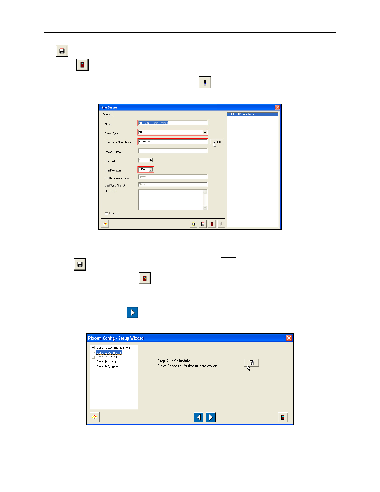
Step 2: Schedule
1. Click on the Next Step
button, to advance to Step 2: Schedule, and the Setup Wizard
screen will appear for Step 2: Schedule (see Figure 46).
Figure 46. Setup Wizard Step 2 Schedule
2-8 ATVS Enterprise Edition v4.2 Installation & Operation Guide
Page 33
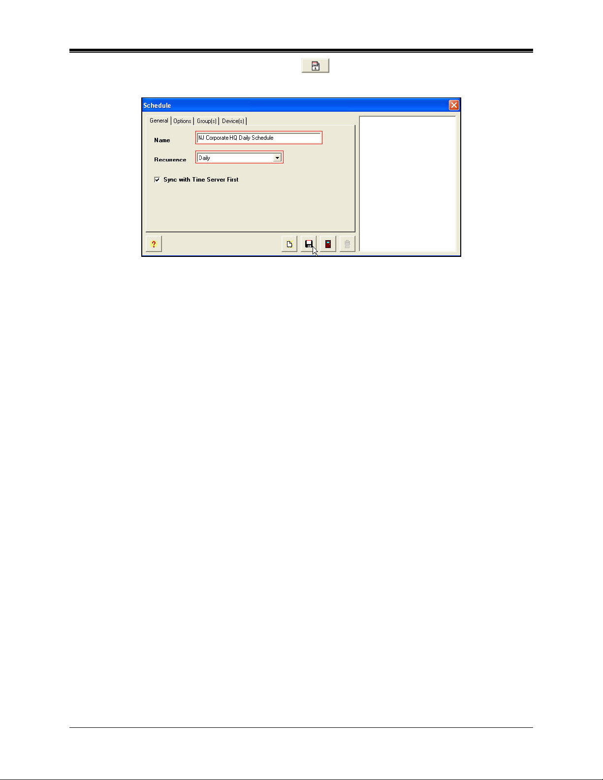
2. For Step 2.1, click on the Create Schedules icon, and the Schedule screen will
appear (see Figure 47).
Figure 47. Schedule General Tab
The Create Schedules icon is used to setup the schedules for time synchronization and
reporting. At these user-specified times, ATVS will synchronize the PIX-3000xN and PIX3000xNT Time Recorders connected to the ATVS.
An unlimited number of schedules and events per day can be set. When creating schedules,
verify that the Sync with Time Server First option is checked. This enables the ATVS to
seek synchronization with a time server first before transmitting the time to all connected
PIX-3000xN and PIX-3000xNT Time Recorders.
If no schedules are set, the system will automatically (by default) attempt to connect to an
NTP server or call the Automated Computer Time Service (ACTS) every day at 3:30 am,
and transmit the time to all connected PIX-3000xN and PIX-3000xNT Time Recorders.
Note: The PC running the ATVS software will always reflect the time retrieved from the time
server. Therefore, the time setting on this PC time may not be the same as your local
time.
If the host PC uses a version of Windows that provides its own atomic clock
synchronization utility, it is recommended to disable this option, as this method is less
accurate and would conflict with the more accurate timekeeping of ATVS.
3. Enter the required General field information. Select the schedule recurrence. The choices
are: Daily, Weekly, Monthly, or Yearly.
4. Click on the Options tab, and an example of a possible screen that could appear is shown
in .
If Daily is selected, then define Every, Start Date [use calendar], Start Time [click in the field
to change time], and check Run Every to set the number of minutes.
If Weekly is selected, then define Recur every week(s) on X day [check box for each day] or
check box for All Week, Start Date [use calendar], and Start Time [click in the field to change
time].
If Monthly is selected, then define Day X of every N month(s), Start Date [use calendar],
and Start Time [click in the field to change time].
If Yearly is selected, then define Every X month for N date, and Start Time [click in the field
to change time].
ATVS Enterprise Edition v4.2 Installation & Operation Guide 2-9
Page 34
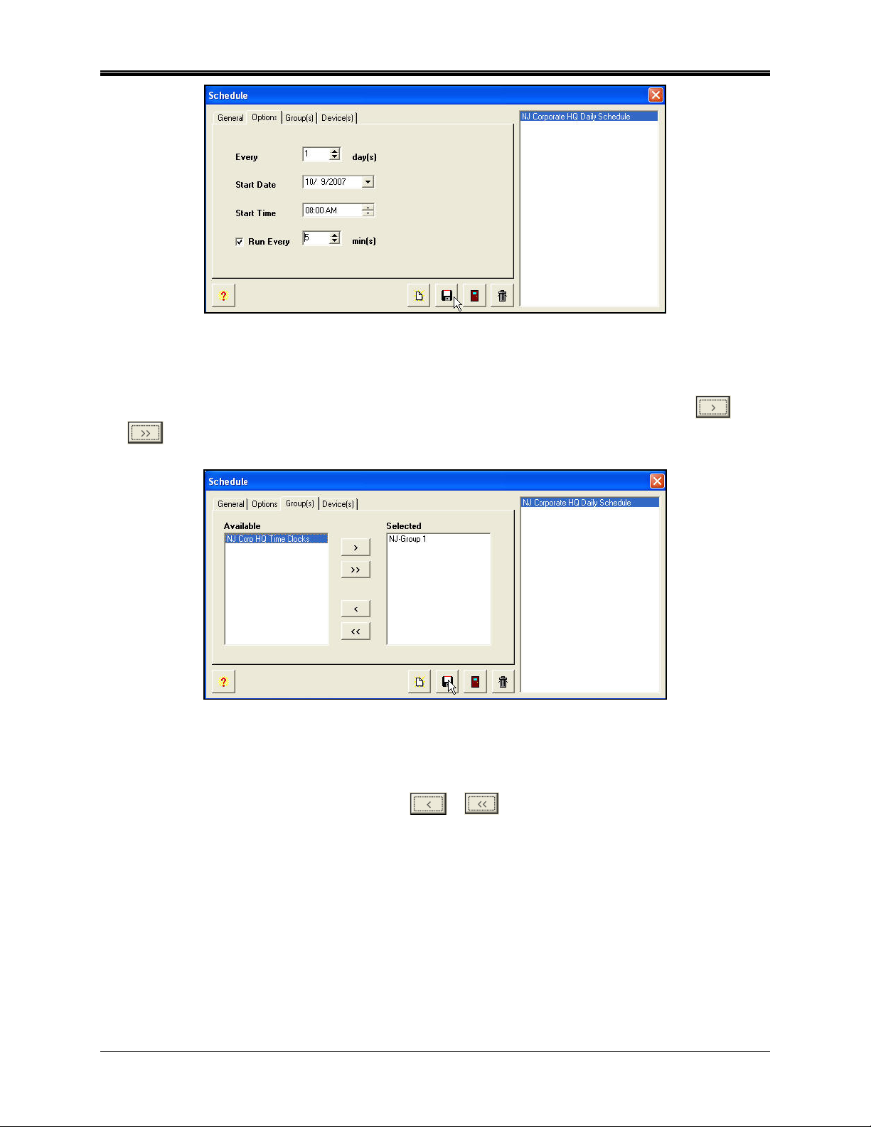
Figure 48. Schedule Options Tab
5. Enter the required Options information. Click on the Group(s) tab, and the screen will
appear as shown in Figure 49. If desired, from the Available list (default status for Groups
previously defined in Step 1.2), select the Group(s) by using the selection arrows (
) to move them to the Selected list on the right from the Available list on the left.
Figure 49. Schedule Group(s) Tab
6. Click on the Device(s) tab, and the screen will appear as shown in . If desired, from the
Selected list (default status for devices previously defined in Step 1.2), deselect the
Device(s) by using the selection arrows (
Selected list on the right to the Available list on the left.
or ) to move them from the default
or
Note: The devices will be automatically selected once the Groups are selected in the previous
step.
2-10 ATVS Enterprise Edition v4.2 Installation & Operation Guide
Page 35
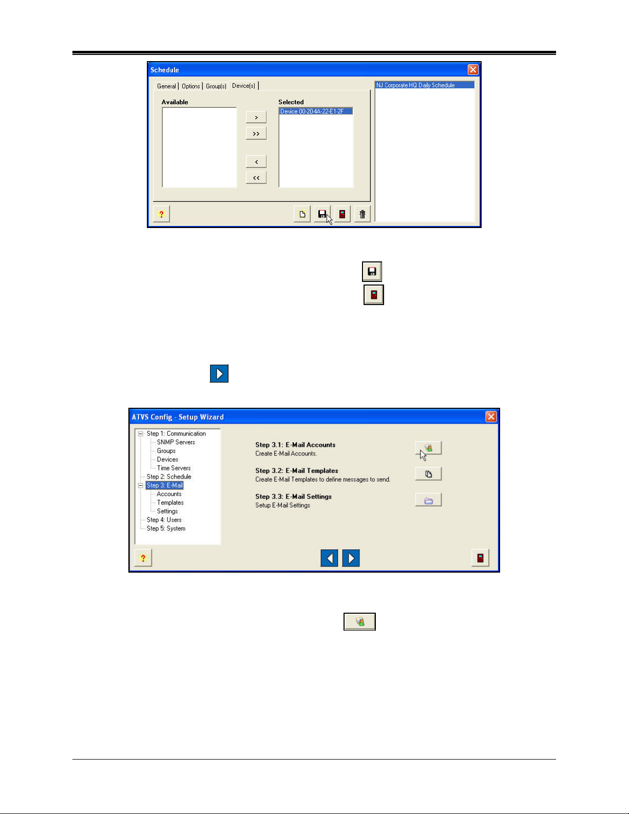
Figure 50. Schedule Device(s) Tab
7. When finished defining a Schedule, click on the Save button to save your Schedule and
return to the Setup Wizard screen. Click on the Close
button to quit without saving. The
new Schedule information will be displayed to the right of the tree view list.
Step 3: E-Mail
1. Click on the Next Step
button, to advance to Step 3: E-Mail, and the Setup Wizard
screen will appear for Step 3: E-Mail (see Figure 51).
Figure 51. Setup Wizard Step 3: E-Mail
2. For Step 3.1, click on the Create E-Mail Accounts icon, and the E-Mail Account
screen will appear (see Figure 52).
ATVS Enterprise Edition v4.2 Installation & Operation Guide 2-11
Page 36
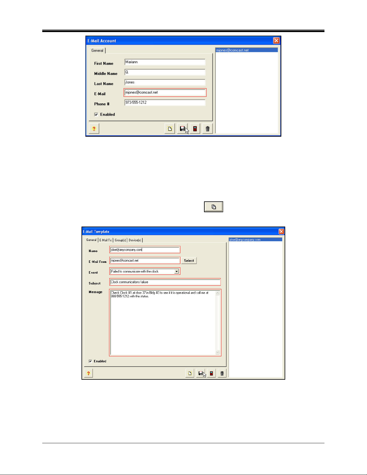
Figure 52. Create E-Mail Account
The Create E-Mail icon is used to setup the E-Mail for status report notification.
The Enabled option, when checked, will automatically send an e-mail notification the remote
support or help desk that the scheduled event has been completed. For proper operation,
the mail (SMTP) server must be specified in Step 1.1, and the addressees and message
must be set in the following E-mail templates.
3. For Step 3.2, click on the Create E-Mail Templates
screen will appear (see Figure 53).
Figure 53. E-Mail Template General Tab
icon, and the E-Mail Template
4. Enter the required general information; Name, E-Mail From [select address from previously
defined address by pressing the Select button – see Figure 54], Event [select from
dropdown list, Subject, and Message.
2-12 ATVS Enterprise Edition v4.2 Installation & Operation Guide
Page 37

Figure 54. E-Mail Account(s) For From
5. Then click on the E-Mail To tab, and the screen will appear as shown in Figure 55. From the
Available list (e-mail addresses previously defined in Step 3.1), select the desired emails by
using the selection arrows (
or ) to move them to the Selected list on the right.
Figure 55. E-Mail Template E-Mail To Tab
6. Enter the required E-Mail To information. Figure 56 is an example of the ATVS system
sending an e-mail notification to the designated E-Mail To recipient.
ATVS Enterprise Edition v4.2 Installation & Operation Guide 2-13
Page 38
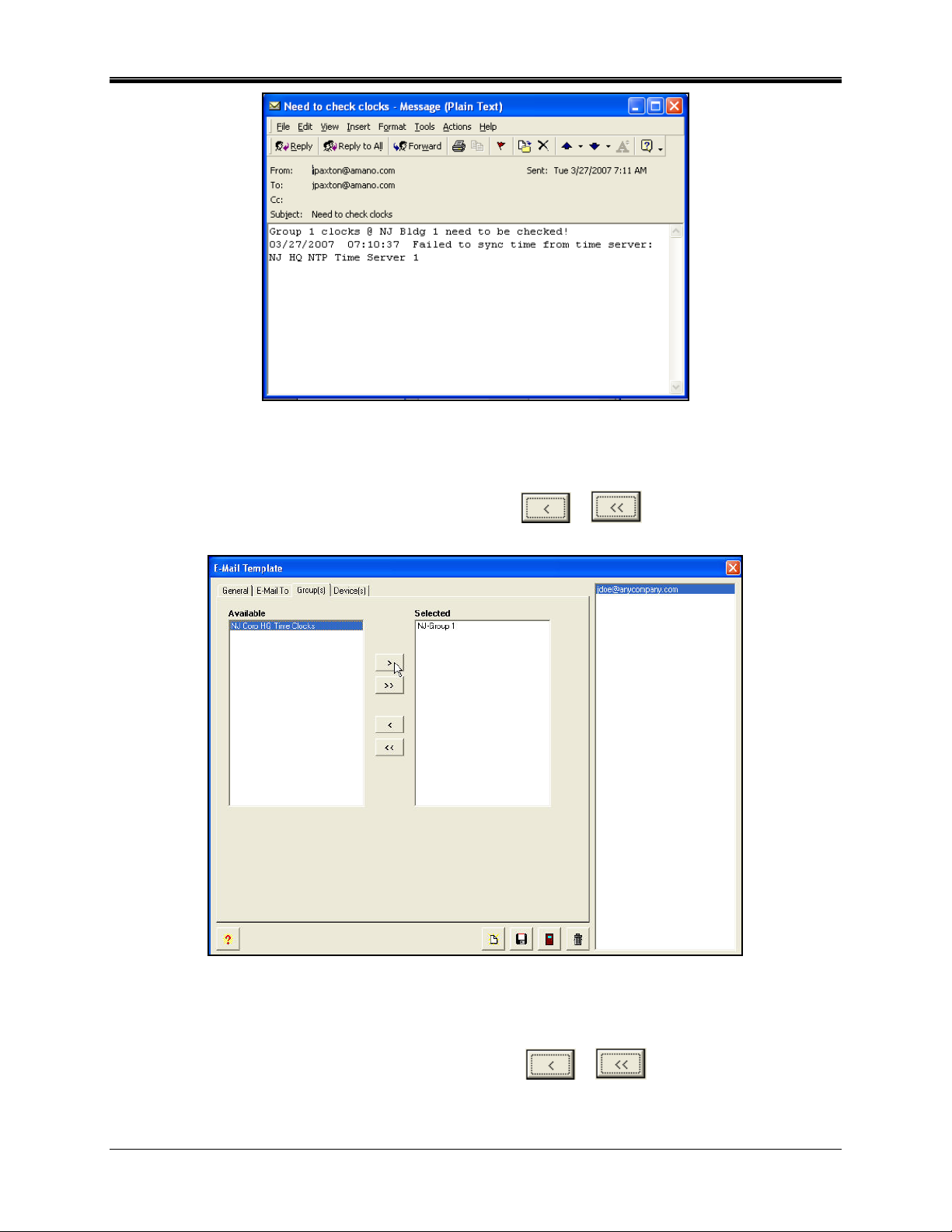
Figure 56. Example of E-Mail Notification
Then click on the Group(s) tab, and the screen will appear as shown in Figure 57. If
desired, from the Selected list (default status for devices previously defined in Step 1.2),
select the Group(s) by using the selection arrows (
default Selected list on the right to the Available list on the left.
Figure 57. E-Mail Template Group(s) Tab
or ) to move them from the
7. Then click on the Device(s) tab, and the screen will appear as shown in Figure 58. If
desired, from the Selected list (default status for devices previously defined in Step 1.3),
select the Device(s) by using the selection arrows (
or ) to move them from the
default Selected list on the right to the Available list on the left.
2-14 ATVS Enterprise Edition v4.2 Installation & Operation Guide
Page 39
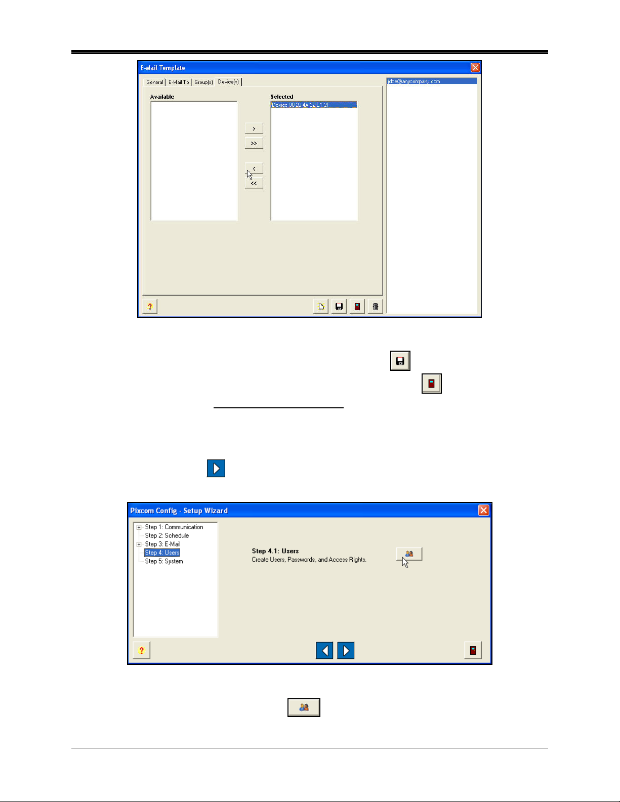
Figure 58. E-Mail Template Device(s) Tab
8. When finished defining an E-Mail account, click on the Save button to save your E-Mail
settings and return to the Setup Wizard screen. Click on the Close
without saving. The new general E-Mail information
will be displayed to the right of the tree
button to quit
view list.
Step 4: Users
1. Click on the Next Step
button, to advance to Step 4: Users, and the Setup Wizard
screen will appear for Step 4:Users (see Figure 59).
Figure 59. Setup Wizard Step 4: Users
2. For Step 4.1, click on the Create Users icon, and the Users screen will appear (see
Figure 60).
ATVS Enterprise Edition v4.2 Installation & Operation Guide 2-15
Page 40
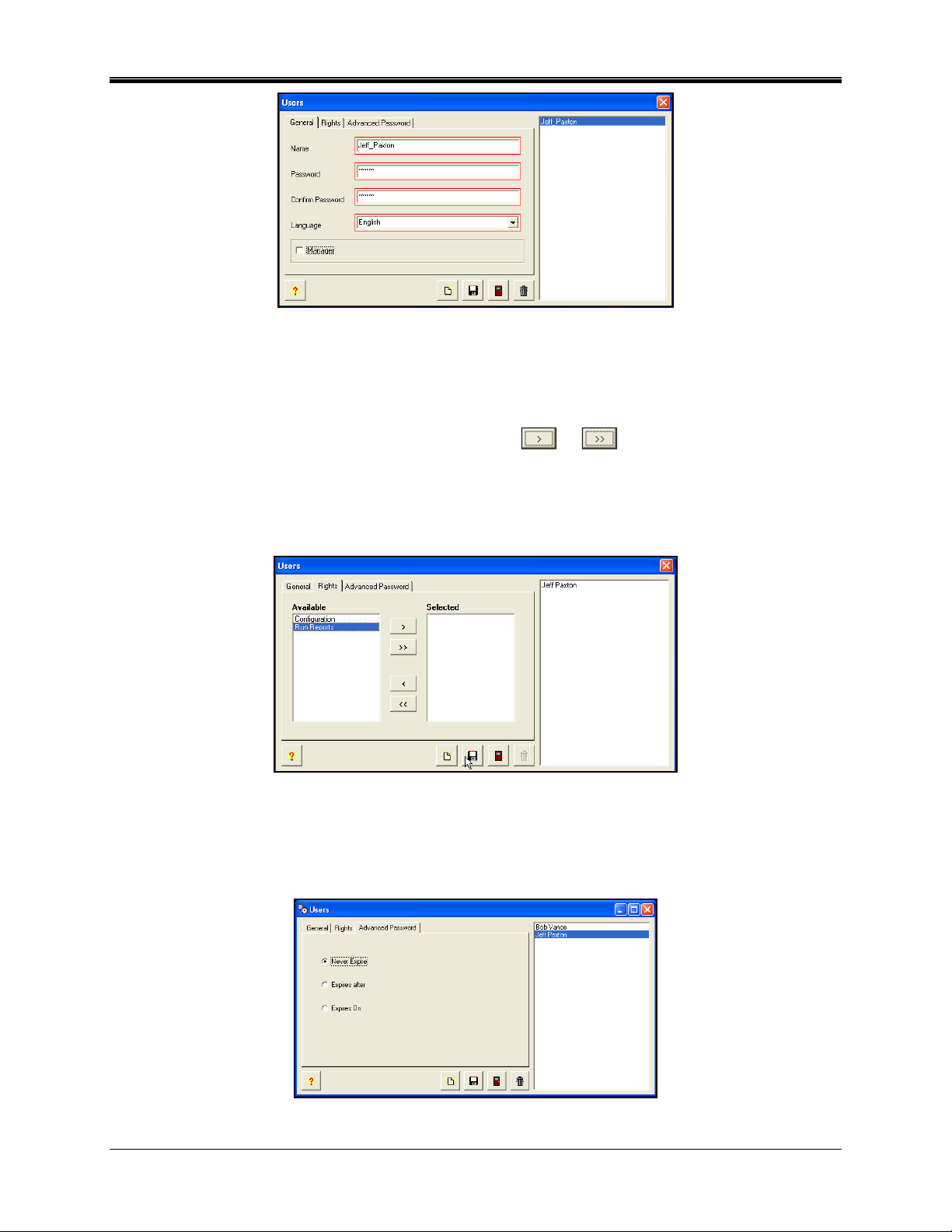
Figure 60. Users General Tab
Note: Any Users already created appear in the pane at the window's right.
3. Enter the required general user field information. If Manager is not checked, click on the
Rights tab, and the screen will appear as shown in Figure 61. From the Available list, select
one or more Rights by using the selection arrows (
or ) to move them to the
Selected list on the right. At least one right must be selected for the User to exist in the
system.
Note: If Manager is checked, then the "Rights" tab will not appear as all rights will automatically
be assigned to this user. This is the default setting.
Figure 61. Users Rights Tab
4. Click on the Advanced Password tab, and the screen will appear as shown in Figure 62.
From the 3 choices select one of the following for the highlighted user: Never Expire,
Number of Days, or Specific Date. The default is Never Expire.
Figure 62. Users Advanced Password Tab
2-16 ATVS Enterprise Edition v4.2 Installation & Operation Guide
Page 41
6. When finished entering each new User, click on the Save button to save the User
settings. When finished creating all new Users, click on the Close
button to quit, and
return to the Setup Wizard screen.
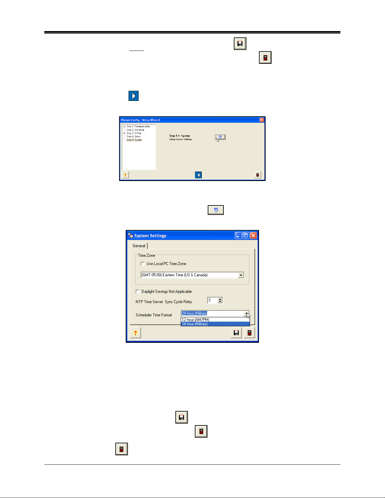
Step 5: System
1. Click on the Next Step
button, to advance to Step 5: System, and the Setup Wizard
screen will appear for Step 5: System (see Figure 63).
Figure 63. Setup Wizard Step 5: System
2. For Step 5.1, click on the Setup System Settings icon, and System Settings will
appear (see Figure 64).
Figure 64. General System Settings
3. Use the local PC time zone, or select the desired time zone, and check whether or not
daylight savings is applicable. Note that the Time Zone selected determines the Time Zone
for only the PC on which ATVS is installed, and is independent of the Time Zone for each
PIX-3000 clock connected to that PC (each PIX-3000 may have its Time Zone separately
configured). Select the number from the dropdown for the NTP Time Server Sync Cycle
Retry. Also, set the time format for the ATVS Scheduler to display. When finished defining
the System settings, click on the Save
the Setup Wizard screen. Click on the Close
4. Click on the Close
button on the bottom of the Setup Wizard to Exit and finish.
button to save the System settings and return to
button to quit without saving.
ATVS Enterprise Edition v4.2 Installation & Operation Guide 2-17
Page 42

Using ATVS Config
How to Create Users
1. Click on the Users
icon in the tree view (see Figure 65), and the previously defined
Users will appear to the right of the tree view.
Figure 65. Select Users
2. Select the Add button on the bottom of the displayed Users, and the Users screen will
appear (see Figure 66).
Figure 66. Users General Tab
Note: Any Users already created appear in the pane at the window's right.
3. Enter the required general user field information. If Manager is not checked, click on the
Rights tab, and the screen will appear as shown in Figure 67. From the Available list, select
one or more Rights by using the selection arrows (
or ) to move them to the
Selected list on the right. At least one right must be selected for the User to exist in the
system.
Note: If Manager is checked, then the "Rights" tab will not appear as all rights will automatically
be assigned to this user. This is the default setting.
2-18 ATVS Enterprise Edition v4.2 Installation & Operation Guide
Page 43
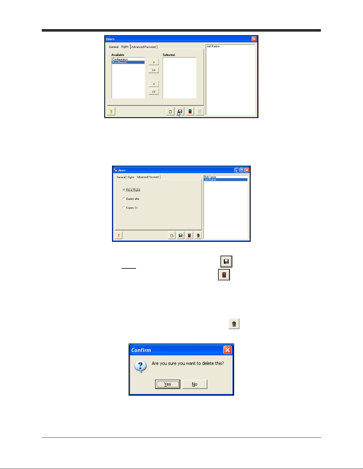
Figure 67. Users Rights Tab
4. Click on the Advanced Password tab, and the screen will appear as shown in Figure 68.
From the 3 choices select one of the following for the highlighted user: Never Expire,
Number of Days, or Specific Date. The default is Never Expire.
Figure 68. Users Advanced Password Tab
5. When finished entering each new User, click on the Save button to save the User.
When finished creating all new Users, click on the Close
button to quit.
How to Delete Users
1. To delete an User in ATVS Config, click on Users in the tree view (see Figure 65
2. Select the desired User from the list, and click on the Delete
button. A dialog box will
).
appear to confirm the deletion (see Figure 69).
Figure 69. Confirm Deletion Dialog
3. Clicking on the Yes button will delete the selected User.
ATVS Enterprise Edition v4.2 Installation & Operation Guide 2-19
Page 44

How To Modify Users
1. Select a User from the list (see Figure 65), and double-click on it, or click on the Edit
button.
2. Type in the modified information (see How Create a User) for the User and click on the Save
button. The modified User will be displayed in the tree view list.
How to Create an SNMP Server
1. Click on the SNMP Servers
icon in the tree view (see Figure 70), and the previously
defined SNMP Servers will appear to the right of the tree view.
Figure 70. Select SNMP Servers
2. Select the Add button on the bottom of the displayed SNMP Servers, and the SNMP
Server screen will appear (see Figure 71). Enter information into the required fields: Name,
IP Address, Port, and Community Name.
Figure 71. Create SNMP Server
Note: All fields outlined in Red should be completed.
3. When finished defining an SNMP Server, click on the Save
Server, or click on the Close
button to quit without saving. The new SNMP Server
button to save your SNMP
information will be displayed to the right of the tree view list.
2-20 ATVS Enterprise Edition v4.2 Installation & Operation Guide
Page 45

How to Delete an SNMP Server
1. To delete an SNMP Server in ATVS Config, click on SNMP Servers in the tree view (see
Figure 70).
2. Select the desired SNMP Server from the list, and click on the Delete
button. A dialog
box will appear to confirm the deletion (see Figure 72).
Figure 72. Confirm Deletion Dialog
3. Clicking on the Yes button will delete the selected SNMP Server.
How To Modify an SNMP Server
1. Select an SNMP Server from the list (see Figure 70), and double-click on it, or click on the
Edit
button.
2. Type in the modified information (see How Create an SNMP Server) for the SNMP Server
and click on the Save
button. The modified SNMP Server will be displayed in the tree
view list.
How to Create A Schedule
The Schedules icon is used to setup the schedules for time synchronization and reporting. At
these user-specified times, ATVS will synchronize the PIX-3000xN and PIX-3000xNT Time
Recorders connected to the ATVS.
An unlimited number of schedules and events per day can be set. When creating schedules,
verify that the Sync with Time Server First option is checked. This enables the ATVS to seek
synchronization with a time server first before transmitting the time to all connected PIX-3000xN
and PIX-3000xNT Time Recorders.
If no schedules are set, the system will automatically (by default) attempt to connect to an NTP
server or call the Automated Computer Time Service (ACTS) every day at 3:30 am, and
transmit the time to all connected PIX-3000xN and PIX-3000xNT Time Recorders.
Note: The PC running the ATVS software will always reflect the time retrieved from the time
server. Therefore, the time setting on this PC time may not be the same as your local
time.
If the host PC uses a version of Windows that provides its own atomic clock
synchronization utility, it is recommended to disable this option, as this method is less
accurate and would conflict with the more accurate timekeeping of ATVS.
1. Click on the Schedules icon in the tree view (see Figure 73), and the previously
defined Schedules will appear to the right of the tree view.
ATVS Enterprise Edition v4.2 Installation & Operation Guide 2-21
Page 46

Figure 73. Create Schedule
2. Select the Add button on the bottom of the displayed Schedules, and the Schedule
screen will appear (see Figure 74).
3. Enter the required General field information. Select the schedule recurrence. The choices
are: Daily, Weekly, Monthly, or Yearly.
Figure 74. Schedule General Tab
4. Click on the Options tab, and an example of a possible screen that could appear is shown
in Figure 75.
If Daily is selected, then define Every, Start Date [use calendar], Start Time [click in the field
to change time], and check Run Every to set the number of minutes.
If Weekly is selected, then define Recur every week(s) on X day [check box for each day] or
check box for All Week, Start Date [use calendar], and Start Time [click in the field to change
time].
If Monthly is selected, then define Day X of every N month(s), Start Date [use calendar],
and Start Time [click in the field to change time].
If Yearly is selected, then define Every X month for N date, and Start Time [click in the field
to change time].
2-22 ATVS Enterprise Edition v4.2 Installation & Operation Guide
Page 47

Figure 75. Schedule Options Tab
5. Enter the required Options information. Click on the Group(s) tab, and the screen will
appear as shown in Figure 76. If desired, from the Available list (default status for any
Groups previously defined), select the Group(s) by using the selection arrows (
or )
to move them to the Selected list on the right from the Available list on the left.
Figure 76. Schedule Group(s) Tab
6. Click on the Device(s) tab, and the screen will appear as shown in Figure 77. If desired,
from the Selected list (default status for devices previously defined), deselect the Device(s)
by using the selection arrows (
the right to the Available list on the left.
Note: The devices will be automatically selected once the Groups are selected.
or ) to move them from the default Selected list on
Figure 77. Schedule Device(s) Tab
ATVS Enterprise Edition v4.2 Installation & Operation Guide 2-23
Page 48
7. When finished defining a Schedule, click on the Save button to save your Schedule.
Click on the Close
button to quit without saving. The new Schedule information will be
displayed to the right of the tree view list.
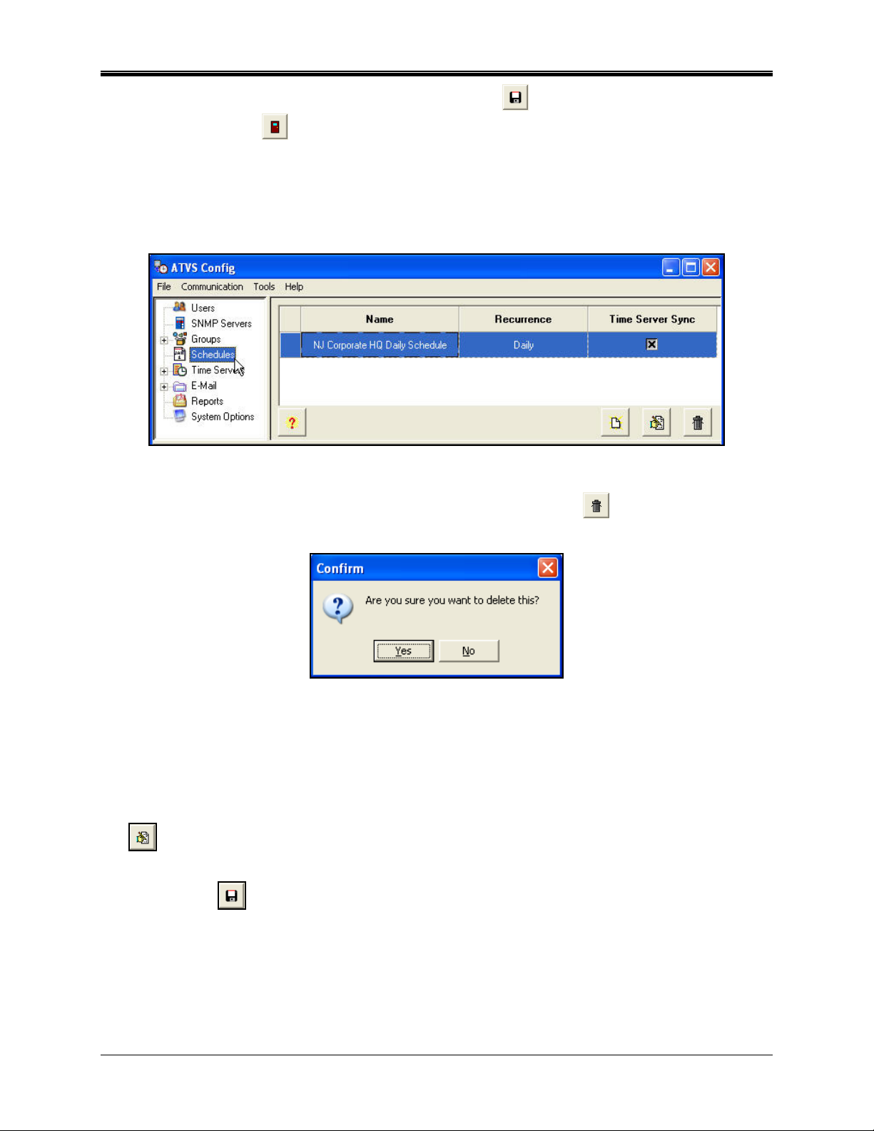
How to Delete A Schedule
1. To delete a Schedule in ATVS Config, click on Schedules in the tree view (see Figure 78).
Figure 78. Select Schedules From Tree View
2. Select the desired Schedule from the list, and click on the Delete button. A dialog box
will appear to confirm the deletion (see Figure 79).
Figure 79. Confirm Deletion Dialog
3. Clicking on the Yes button will delete the selected Schedule.
How To Modify a Schedule
1. Select a Schedule from the list (see Figure 78), and double-click on it, or click on the Edit
button.
2. Type in the modified information (see How Create a Schedule ) for the Schedule and click
on the Save
button. The modified Schedule will be displayed in the tree view list.
2-24 ATVS Enterprise Edition v4.2 Installation & Operation Guide
Page 49
How to Add Groups and Devices
A Group represents a collection of Devices (PIX-3000xN/PIX-3000xNT Time Recorders)
typically within a geographical area, whether that area is a floor, office, or region. Any Device
within a Group may be in one Group, and one Group only. Groups and Devices can be added
and defined from the ATVS Config tree view (see Figure 80).
Figure 80. Select Groups From Tree View
How to Add a PIX-3000xNT to the System
1. Add and define a Group.
2. Add a Device to the Group.
3. Assign a Network Interface Card (NIC) to each Device.
4. Configure communication parameters (IP Addresses and Com Ports) for each Device.
To Add a Group from ATVS
1. Click on the Groups icon in the tree view (see Figure 80), and the previously defined groups
will appear to the right of the tree view.
2. Select the Add
will appear (see Figure 81).
button on the bottom of the displayed Groups, and the Group screen
Figure 81. Groups General Tab
3. To enable all the Devices in the Group, click on the Enabled checkbox.
ATVS Enterprise Edition v4.2 Installation & Operation Guide 2-25
Page 50
4. Enter information into the required Name field, and elective Description field. Click on the
Enabled box to enable all devices in the group. Then click on the SNMP Server(s) tab, and
the screen will appear as shown in Figure 82. Next assign SNMP Servers, from the
Available list (default status for SNMP Servers previously defined), select the SNMP Servers
by using the selection arrows (
or ) to move them to the Selected list on the right
from the Available list on the left.
Figure 82. Groups SNMP Servers Tab
5. When finished entering each new Group, click on the Save button to save the Group
settings. When finished creating all new Groups, click on the Close
button to quit, and
return to the Groups tree view.
How To Modify a Group
1. Select a Group from the list, and double-click on it, or click on the Edit
2. Type in the new name for the Group and click on the Save
button. The renamed Group
button.
will be displayed in the tree view list.
How To Delete a Group
1. Select a Group from the Groups list, and click on the Delete
button.
2. A dialog box will appear to confirm the deletion (see Figure 83). Click on the Yes button.
Figure 83. Confirm Deletion
How To Add a Device to the Group
1. Click on the Groups icon in the tree view, and then expand the Groups list by clicking in the
tree view on the +. All previously defined groups will appear.
2-26 ATVS Enterprise Edition v4.2 Installation & Operation Guide
Page 51

2. Select a Group from the expanded list and click on the Add button for the Device
screen to appear (see ).
3. Enter a Name for the device that describes it in some meaningful way.
4. From the Type dropdown list, select a PIX-3000xN or PIX-3000xNT.
5. If selecting a PIX-3000xNT device, enter its IP Address. If the IP address is unknown,
select the Device Lookup
button to launch the DeviceInstaller program to search for IP
devices. See Chapter 4 for more information on the DeviceInstaller.
6. For the PIX-3000xN, select the desired Com Port from the dropdown list provided.
7. Enter in the Max Deviation that is acceptable to synchronize the Device. The maximum
deviation is determined by the latency of the network. For this reason it should be set to a
minimum value of 400 ms, and adjusted accordingly to a higher number (default is 1500
ms).
8. If you wish to add comments or notes on the device, enter them in the Description field.
9. Select whether or not the device is Enabled by checking the box. The default is enabled.
Figure 84. Adding a Device
10. Then click on the Other Options tab, and the screen will appear as shown in Figure 85.
Either use the local computer's time zone (default), or select the appropriate Time Zone from
the dropdown menu. The Time Zone selected controls the Time Zone adjustment sent to the
selected device. Where OATS compliance is necessary, verify that the Use Local PC Time
Zone option is not checked. The Time Zone must be set to Coordinated Universal Time
(UTC) UTC-5:00 Eastern.
ATVS Enterprise Edition v4.2 Installation & Operation Guide 2-27
Page 52
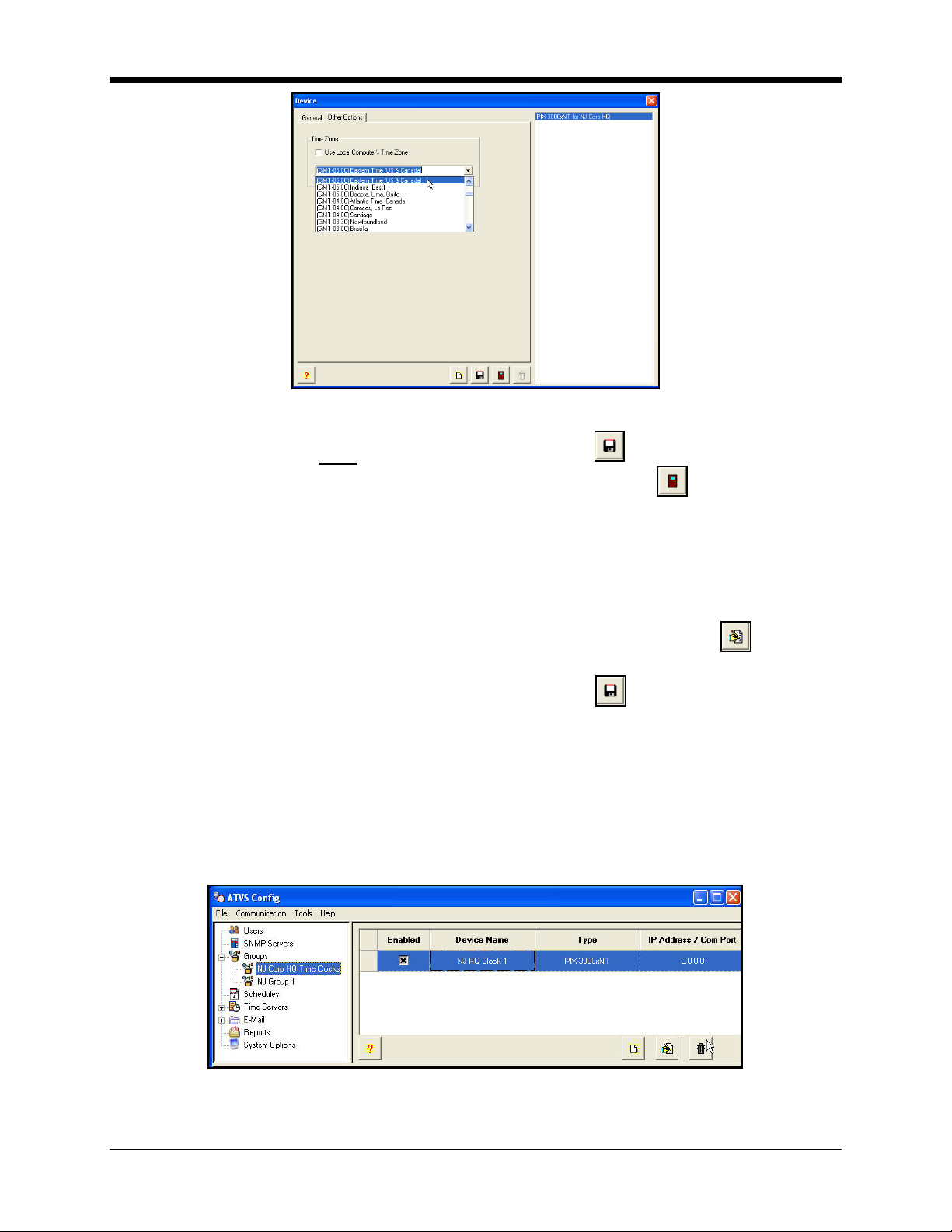
Figure 85. Device Other Options Tab
11. When finished entering each new Device, click on the Save button to save the Device
settings. When finished creating all new Devices, click on the Close
button to quit, and
return to the Groups screen.
How To Rename a Device
1. Click on the Groups icon in the tree view, and then expand the Groups list by clicking in the
tree view on the +. All previously defined groups will appear.
2. Select a Group from the expanded list, double-click on it, or click on the Edit
button,
and the Device screen will appear.
3. Type in the new Name for the Device and click on the Save
button. The renamed
Device will appear to the right of the Group.
How To Delete a Device
1. Click on the Groups icon in the tree view, and then expand the Groups list by clicking in the
tree view on the +. All previously defined groups will appear.
2. Select a Group from the expanded list by clicking on it to highlight the desired Device for
that group (see Figure 86).
Figure 86. Deleting a Device
2-28 ATVS Enterprise Edition v4.2 Installation & Operation Guide
Page 53

3. Click on the Delete button. A confirmation dialog message for deletion will appear, and
click Yes to confirm deletion.
Device Setup and Configuration
Before performing device setup and configuration procedure, you must:
1. Verify that the device (and Ethernet board) is powered and attached to a network via
Ethernet CAT5 cabling.
2. Verify that the IP Address assigned to the device is valid.
3. Obtain the serial number of the Ethernet board installed in the device. This number is
located on the label affixed to PIX-3000xNT box.
General Device Settings
1. To reset the PIX-3000xNT NIC password, click on the Device Settings icon in the tree view.
The PIX-3000xNT Settings screen will appear (see Figure 87).
Figure 87. Device Settings
2. Select the PIX-3000xNT from the list, and click on the Edit button, and the PIX3000xNT Settings screen will appear (see Figure 88).
Figure 88. PIX-3000xNT Settings
ATVS Enterprise Edition v4.2 Installation & Operation Guide 2-29
Page 54
3. Type in the New Password for the PIX-3000xNT's, and confirm. Press the Reset
button, and a dialog screen will appear to confirm the Reset command (see Figure 89). The
new password will be broadcast to all connected PIX-3000xNT's. Every time the password is
Reset with a new password, the new password is retained in a masked status as the old
password. The "old password" is required to maintain connection with the NIC PIX3000xNT's. If the connected devices (PIX-3000xNTs) fail to reset (password), each failed
device will be displayed in the Status window. All device status will be displayed when the
Reset button is pressed, including the number of devices.
Figure 89. Reset Password Warning
Time Servers
The Time Server selection allows you to select up to ten NTP, NIST, NPL, or PTB time servers
to synchronize the ATVS Host. Select NTP as the server type and click on the
button to
see a list of NTP servers (see Figure 90). Select the desired time server from the list, and click
on the
button. Click the Close button when done.
Figure 90. NTP Servers
Note: The ATVS system time must be synchronized with an NTP Server or ACTS before
running ATVS.
How To Add Time Servers
1. Click on the Time Servers icon in the tree view (see Figure 91), and all previously defined
time servers will appear to the right.
Figure 91. Selecting a Time Server
2-30 ATVS Enterprise Edition v4.2 Installation & Operation Guide
Page 55
2. Click on the Add button, and the Time Server screen will appear (see Figure 92).
Figure 92. Adding a Time Server
3. Place a check in the Enabled checkbox to enable the NTP server.
4. Enter a Name, and select the Server Type from the dropdown. The server type choices are:
NTP, NIST (US), NPL (UK), or PTB (DE). For NTP, click on the
button and a list of
NTP servers will appear to choose from (see the following figure).
For NIST, NPL, or PTB, click on the
button and the default modem phone number
for the server will appear in the Phone Number field. Also, the Com Port field will be active
to enter the desired Com Port.
5. Enter in the Max Deviation that is acceptable to synchronize the ATVS Host. The default
value is 1.5 seconds or 1500 ms.
6. The Last Successful Sync and Last Sync Attempt are read-only fields that display the
successful sync and last sync attempt of the schedule. The Description field enables you to
type in comments or remarks about the server.
7. To save these Time Server settings click on the Save
button. The updated Time Server
information will be displayed to the right of the tree view list (see "Deleting Time Servers"
figure for an example).
How To Delete a Time Server
1. Click on the Time Server icon in the tree view, and all previously defined time servers will
appear. Also, a time server can be selected from the list on the right in the time server
screen.
2. Select a time server from the expanded list by clicking on it to highlight the desired time
server (see Figure 93).
ATVS Enterprise Edition v4.2 Installation & Operation Guide 2-31
Page 56
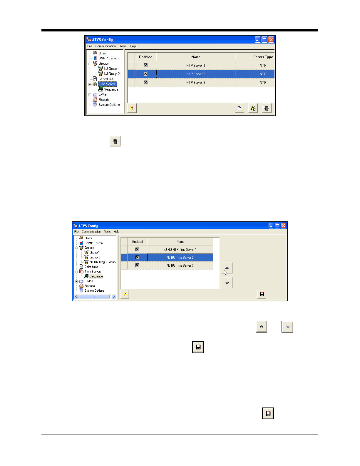
Figure 93. Deleting Time Server
3. Click on the Delete button, and a confirmation dialog message for deletion will appear.
Click Yes to confirm deletion.
How To Define the Time Server Sequence
1. Click on the Time Servers icon in the tree view (see above figure), and then expand the
Time Servers list by clicking in the tree view on the +. All previously defined time servers will
appear.
2. Click on the Sequence icon in the tree view to display the time Servers in sequence (see
Figure 94).
Figure 94. Time Server Sequence
3. Define the sequence order by selecting a time server and using the up and down
move arrows.
4. To save this Sequence setting click on the Save
button.
General System Options
The system settings for ATVS are located in System Options (see Figure 95). These settings
include Time Zone, DST, NTP Time Server Sync Cycle Retry number (# of retries for a sync
failure), and Scheduler Time Format [12 hour AM/PM or Military].
To modify System Options, click on the System Options icon in the tree view, enter the new
information. To save the modified System Options settings click on the Save
button.
2-32 ATVS Enterprise Edition v4.2 Installation & Operation Guide
Page 57

Figure 95. System Options
Time Zone
Use Local PC Time Zone: This option should only be checked in areas where OATS
compliance is not important, but sync to local time is.
However, for OATS compliance, verify that the Use Local PC Time Zone option is not checked.
The Time Zone must be set to Coordinated Universal Time (UTC) UTC -5:00 Eastern.
Daylight Savings Time Not Applicable: This option should only be checked in areas where
DST is not used, and OATS compliance is not required.
Scheduler Time Format: From the dropdown menu select either 24 hour military, or 12 hour
(AM/PM).
General E-Mail Settings
The E-Mail settings for ATVS are located in E-Mail. These settings include SMTP Server Name,
Port, Authentication required [Username and Password], and whether or not secure connection
(SSL) is required.
To modify general E-Mail settings, click on the E-Mail icon in the tree view (see Figure 96), and
enter the new information. To save the modified general e-mail settings click on the Save
button.
Figure 96. General E-Mail Settings
ATVS Enterprise Edition v4.2 Installation & Operation Guide 2-33
Page 58

How To Delete E-Mail Account and/or Template
1. Click on the E-Mail icon in the tree view, and then expand the E-Mail list by clicking in the
tree view on the +. All previously defined e-mail accounts and templates will appear when
you click on the Accounts or Templates icon in the tree view.
2. Select an E-Mail Account or Template from the expanded list by clicking on it to highlight
the desired account or template for the e-mail notification (see Figure 97 and Figure 98).
Figure 97. Deleting E-Mail Account
Figure 98. Delete E-Mail Template
3. Click on the Delete button, and a confirmation dialog message for deletion will appear.
Click Yes to confirm deletion.
How To Add E-Mail Account and/or Template
1. Click on the Accounts or Templates icon in the tree view (see Figure 97 and Figure 98), and
all previously defined E-Mail Accounts or Templates will appear to the right of the icon.
2. Click on the Add button, and the E-Mail Account or E-Mail Template screen will appear
depending on which was selected (see Figure 99 and Figure 100).
Figure 99. Add E-Mail Account
2-34 ATVS Enterprise Edition v4.2 Installation & Operation Guide
Page 59
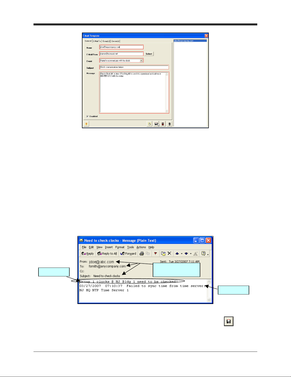
p
Figure 100. Add E-Mail Template
In the E-Mail Account screen, the E-Mail To field is where the e-mail notification from ATVS
will be sent.
In the E-Mail Template screen, the From E-Mail field is the From e-mail on the notification
(i.e., a clock failed to sync message sent) e-mail sent by the ATVS. The Message, Event,
and Time Server Name information will appear in the e-mail. Also, the Subject field will be
included. See the following example figure.
3. Place a check in the Enabled checkbox in the E-Mail Account screen to enable that e-mail
account for use.
4. Place a check in the Enabled checkbox in the E-Mail Template screen to enable that e-mail
template for use.
5. For the E-Mail Template, enter a Name, select the From E-Mail from the dropdown, and
select the Event from the dropdown. Enter the Subject (see Figure 101 for an example email notification sent by ATVS) and desired Message.
Message
Figure 101. Example of E-Mail Notification
Info from
E-Mail Tem
late
Event
6. To save these E-Mail Account and E-Mail Template settings click on the Save button.
The updated E-Mail Account and Template information will be displayed to the right of each
tree view list (see "E-Mail Account List" Figure 97 for an example).
ATVS Enterprise Edition v4.2 Installation & Operation Guide 2-35
Page 60

This page intentionally left blank.
2-36 ATVS Enterprise Edition v4.2 Installation & Operation Guide
Page 61

Chapter 3: ATVS Scheduler Operation
The ATVS Scheduler runs as a service for the ATVS Enterprise Edition software. The ATVS
Scheduler window consists of two tabs: Actions and Previous Action Log.
To start the ATVS Scheduler, click on the ATVS Scheduler
Scheduler screen will appear (see Figure 102).
Figure 102. ATVS Scheduler
icon and the ATVS
At startup, the ATVS Scheduler will check each device and verify the assigned NIC IP Address.
If the NIC IP Address is invalid, an error message will appear in the Actions Log stating that the
device does not have a valid IP Address.
To correct this you must open the ATVS Config program by clicking on the ATVS
Icon.
Click on the Tools Menu in ATVS Config, and select the sub-menu Device Lookup, which will
launch DeviceInstaller (see Chapter 4). From DeviceInstaller you have to either assign another
NIC to the affected device(s), or re-enter the IP address of the NIC in question.
Actions Log
The Actions tab functions as a real-time monitor of actions performed by the ATVS Host.
As each action is performed, its description with date and time is displayed as a line item. When
completed, the next scheduled action to occur is listed with the date and time. For an
explanation of the events recorded, click on the Help button or refer to Chapter 5 for a complete
listing of messages.
Note: A message in the actions log in blue indicates a warning, while a message in red
indicates a failed task (see ).
ATVS Enterprise Edition v4.2 Installation & Operation Guide 3-1
Page 62
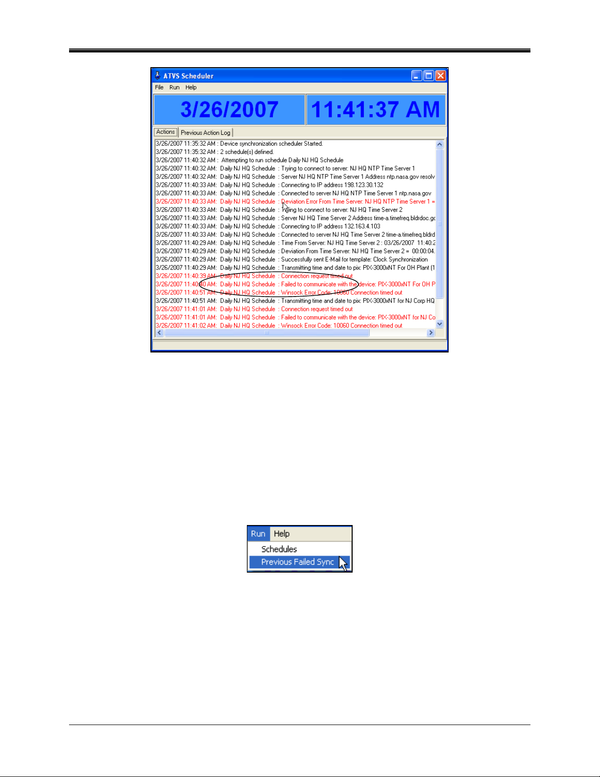
Figure 103. ATVS Scheduler Actions Log
These messages will continue to be displayed on the screen for up to 200 scrollable lines, at
which time the system will automatically save them to a database. A database is created for
every day ATVS is run, and then archived by the system. Previous databases can be viewed on
screen in the Previous Action Log tab or by using ATVS Reports.
From the menu click on File, and select Clear to clear the currently displayed Actions Log.
The system can be operated manually through the use of the menu selections. This will attempt
to obtain the correct time from an NTP server or NIST-ACTS before the devices are
synchronized. This is accomplished by using the Previous Failed Sync sub-menu selection
from the Run menu in ATVS Scheduler (see Figure 104).
Figure 104. Run Menu in ATVS Scheduler
After selecting "Previous Failed Sync", click on the devices you want to sync and then click on
the Sync button (see Figure 105).
3-2 ATVS Enterprise Edition v4.2 Installation & Operation Guide
Page 63

Figure 105. Sync Previously Failed Sync Device(s)
From the Run menu select Schedules from ATVS Scheduler (see Figure 106), select a
schedule(s) [previously defined], and click on the Run
button to execute that
schedule(s).
Figure 106. Run Schedules From ATVS Scheduler
ATVS Enterprise Edition v4.2 Installation & Operation Guide 3-3
Page 64
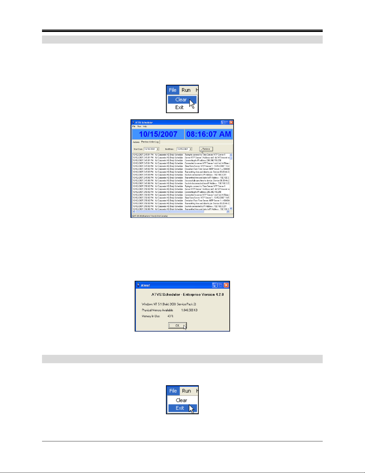
Previous Action Log
The Previous Action Log tab allows you to access the database generated when the Action
Log is automatically saved. A database is generated every day ATVS is run.
From the menu click on File, and select Clear (see Figure 107) to clear the currently displayed
Previous Action Log (see Figure 107).
Figure 107. Previous Action Log
To retrieve a Previous Action Log, enter a start and end date in the appropriate fields and click
on the Retrieve button. If the database exists, its contents will be displayed (see Figure 107).
For an explanation of the events recorded in the database, click on the Help button or refer to
Chapter 5 for a complete listing of messages. Click on Help menu and select About (see Figure
108) for the ATVS Scheduler version.
Figure 108. ATVS Scheduler About
Exiting The Program
From the File menu, click on Exit to close the ATVS Scheduler window. However, ATVS
Scheduler will still be running as a service in the background for the Enterprise version.
3-4 ATVS Enterprise Edition v4.2 Installation & Operation Guide
Page 65

Chapter 4: DeviceInstaller Use
DeviceInstaller can be used to find and or configure devices for ATVS. To launch
DeviceInstaller from ATVS Config click on the Tools menu, and then select the Device Lookup
sub-menu. Figure 109 shows the DeviceInstaller main menu.
Click on the Magnifying glass to use the search tool to locate PIX-3000xNT IP addresses.
The hardware/MAC address will be required and this can be obtained on the PIX-3000xNT from
a label on the Time Recorder.
Figure 109. DeviceInstaller Main View
Importing Device IP/MAC Address
1. The DeviceInstaller can also be launched from ATVS Config application by going to the
Groups icon in the tree view, and then expanding the Groups list by clicking in the tree view
on the +. All previously defined groups will appear.
2. Select a Group from the expanded list and click on the Add
will appear (see Figure 110).
Figure 110. Device Search
button. The Device screen
3. From the Device screen, click on the Device Lookup button, and the DeviceInstaller
will launch.
ATVS Enterprise Edition v4.2 Installation & Operation Guide 4-1
Page 66
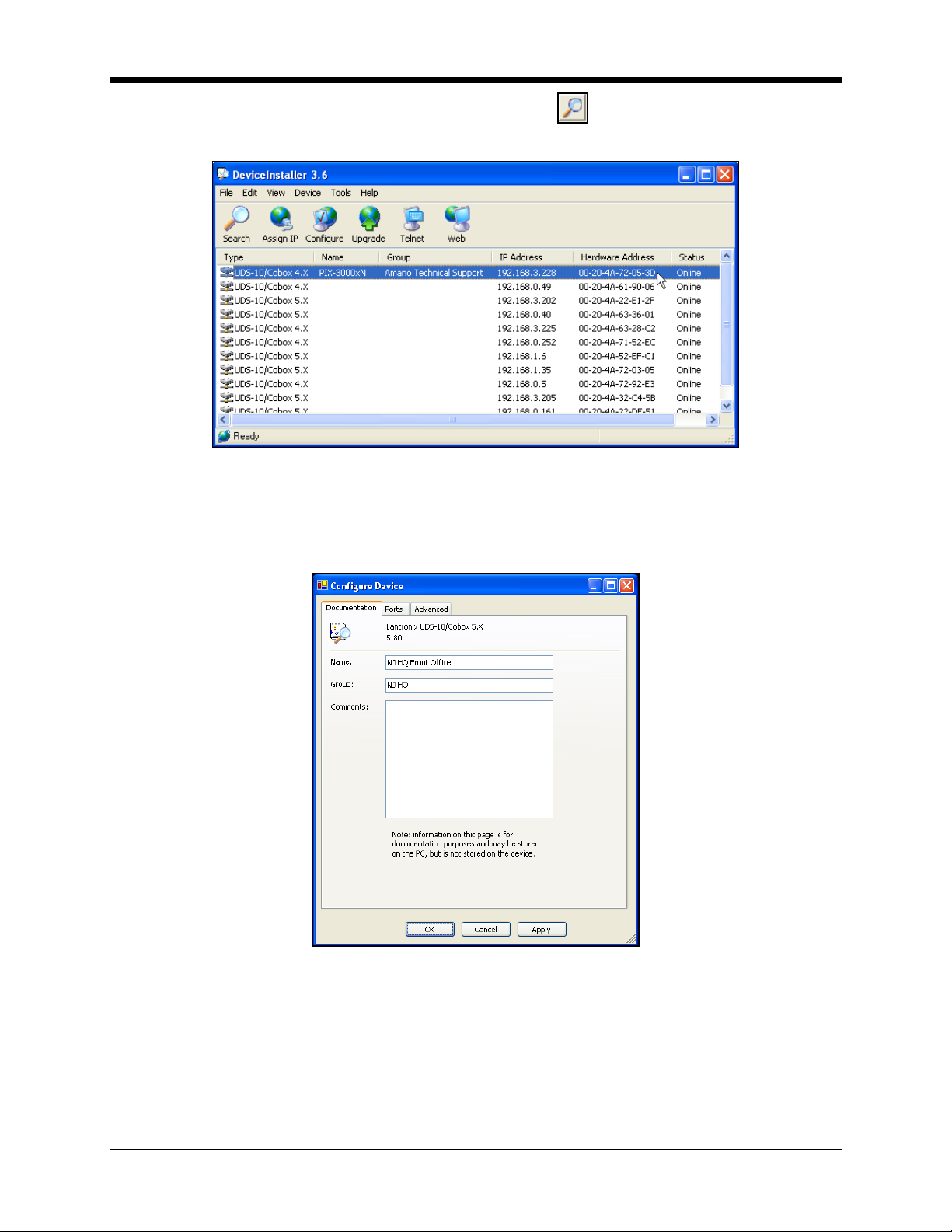
4. From the DeviceInstaller, click on the Magnifying glass to use the search tool to locate
the PIX-3000xNT IP/Mac addresses. Figure 111 shows an example of a search.
Figure 111. DeviceInstaller Search Results Example
5. Any devices that are detected here may be imported. If you wish to define a specific group
for the device to be imported into, double-click on the device and the Configure Device
screen will appear (see Figure 112).
Figure 112. Configure Device
6. The Configure Device screen allows you to define a name and Group for the device.
Defining a Group here provides the DeviceInstaller import utility with the necessary
information to install the device into the specified Group. To specify a Group, enter the
Group name exactly as it appears in the Groups menu in ATVS Config. When done, select
OK.
4-2 ATVS Enterprise Edition v4.2 Installation & Operation Guide
Page 67
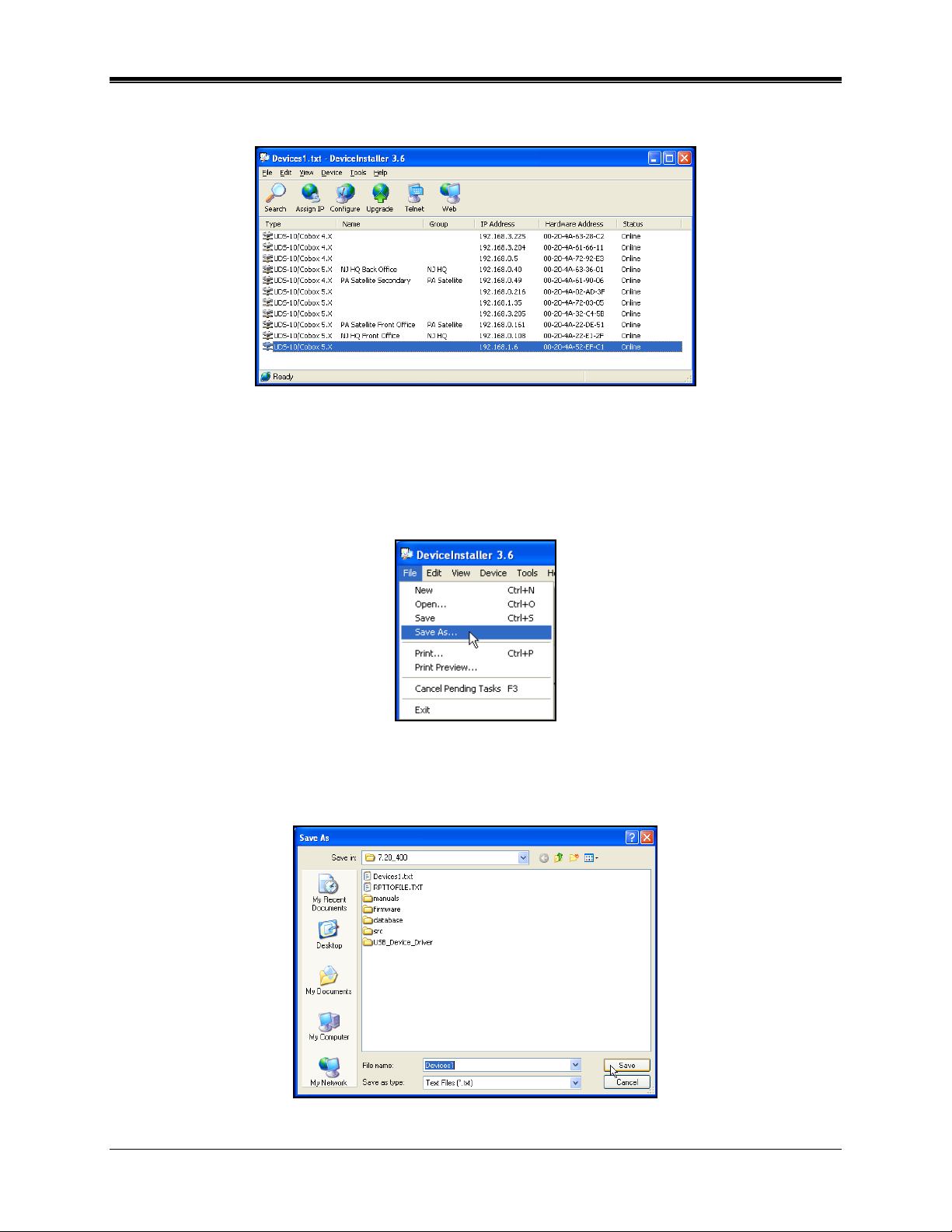
Update the Group for all devices you wish to define. All pre-defined devices will appear in
the DeviceInstaller grid (see Figure 113) with the Group defined in the Group heading.
Figure 113. DeviceInstaller Grid Results Example
If no group is specified, each device imported will automatically be installed to a default
group. If the group associated to a device needs to be changed at a later time, please refer
to the section Moving a Device to Another Group on page 4-5.
7. Click on File and select the Save As sub-menu (see Figure 114).
Figure 114. DeviceInstaller File Menu
8. From the Save As dialog (see ) select a destination folder [Save in:] and File name. Click
the Save button and a text file with the IP search results will be saved.
Figure 115. Save As Dialog
ATVS Enterprise Edition v4.2 Installation & Operation Guide 4-3
Page 68
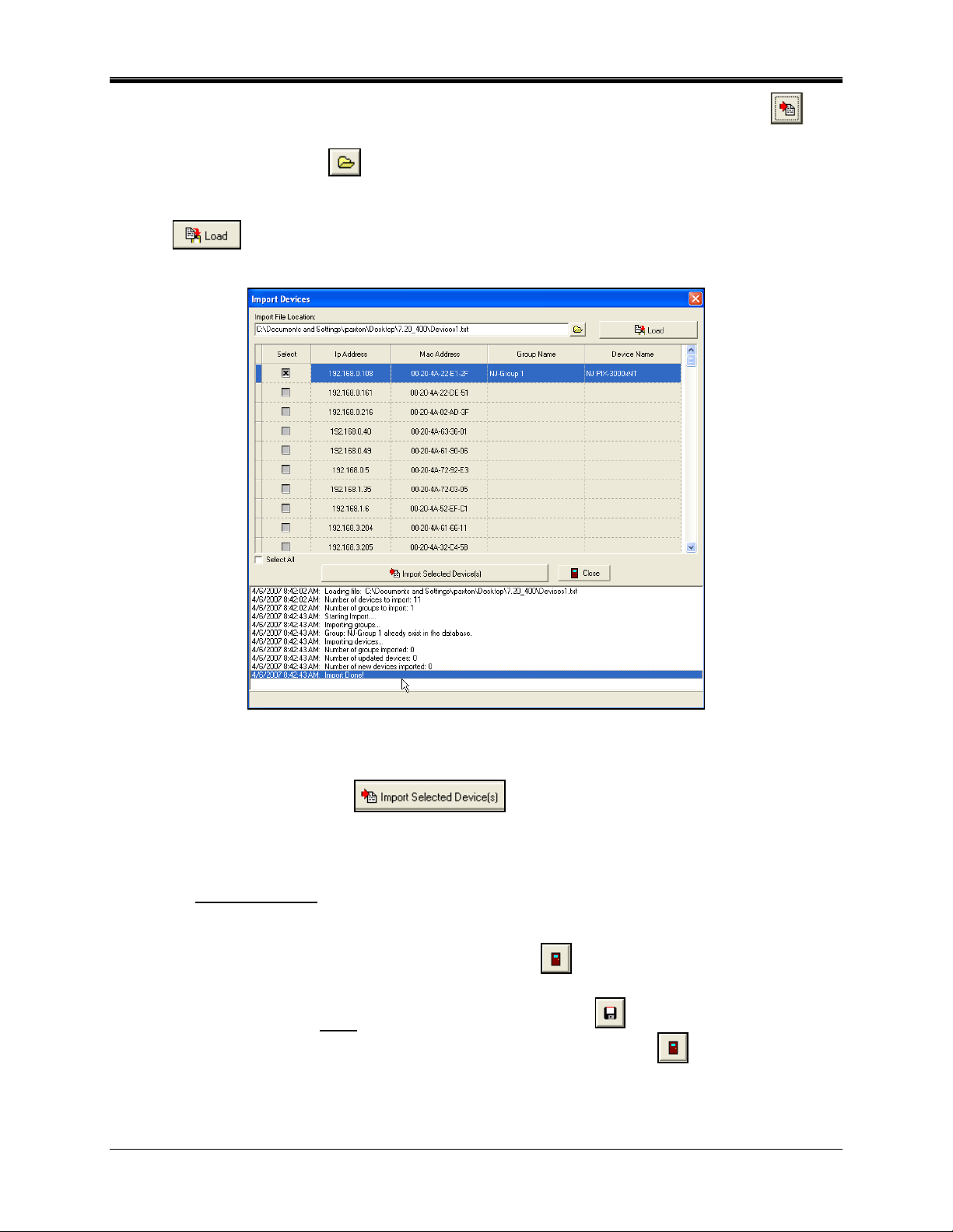
9. Close the DeviceInstaller, and from the Device screen click on the Import Devices
button and a blank Import Devices screen will appear. Click alongside the Import File
Location on the Browse
button and navigate to the saved Devices txt file from the
previous step. Once the file is selected, click on the Open button and the path for the text
file with the IP search results will appear in the "Import File Location" field. Click on the Load
File
button and the device information will appear on the Import Devices screen
(see ).
Figure 116. Import Devices Example
10. Select the desired device to import (load) by clicking in the "Select" box, and click on the
Import Selected Device(s)
button and the dialog "Are you sure you
want to import these devices?" will appear. Click on Yes to import the device(s). The status
display on the bottom of the Import Devices screen will show the device import transaction
(see above figure for an example).
Note: The Description field
on the Device screen will be auto populated with the text; " This
device was created in the import module." If the Import Module is used to create the
device.
11. When finished importing Devices, click on the Close
button to quit, and return to the
Device screen.
12. When finished entering each
settings. When finished creating all new Devices, click on the Close
new Device, click on the Save button to save the Device
button to quit, and
return to the Device listing screen (tree view).
4-4 ATVS Enterprise Edition v4.2 Installation & Operation Guide
Page 69
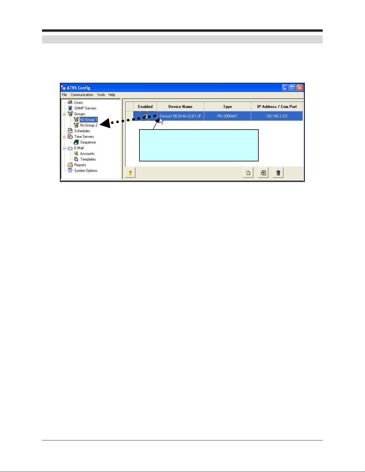
Moving a Device to Another Group
1. Click on the Groups icon in the tree view, and then expand the Groups list by clicking in the
tree view on the + to list devices. All previously defined groups and associated devices will
appear (see Figure 117). To the right of the Groups shown in the tree view will be a list of
the devices connected to that group.
Example - Drag and drop the device from
group1 to group2 (another) by dragging a
device on top of a different group name
in the tree view.
Figure 117. Drag and Drop a Device
2. To move a device, select a device from the expanded list by clicking on it, hold down the
mouse button, and drag-n-drop the device on top of the group in the tree view on the left
that you want to move it to (see above figure).
Note – when a device is imported using the importing procedure a group name will
automatically be created. If this occurs, it might be necessary to move a device to the
desired group name. If a blank group (non-desired) group remains, move up in the tree view
to the group level and delete it.
ATVS Enterprise Edition v4.2 Installation & Operation Guide 4-5
Page 70

This page intentionally left blank.
4-6 ATVS Enterprise Edition v4.2 Installation & Operation Guide
Page 71
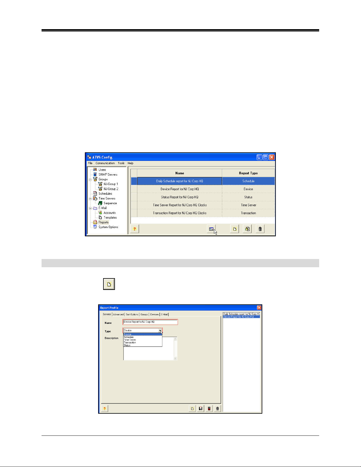
Chapter 5: ATVS Reports
ATVS Reports enables the user to generate, view, save the report file, and print reports
containing:
• Device settings.
• Device synchronization schedules by Schedule or by day of the week.
• Time sources (NTP servers and dial-up services).
• The transaction log by specific date or date range.
• The status and condition of each Device in the system.
Figure 118 shows an example of what the reports listing looks like after clicking on the Reports
icon from the tree view.
Figure 118. ATVS Config Reports
How To Create a Report
1. Click on the Reports icon in the tree view, and any previously defined Reports will appear.
2. Click on the Add
119).
button, and the blank Report Profile screen will appear (see Figure
Figure 119. Creating A Report Profile
ATVS Enterprise Edition v4.2 Installation & Operation Guide 5-1
Page 72
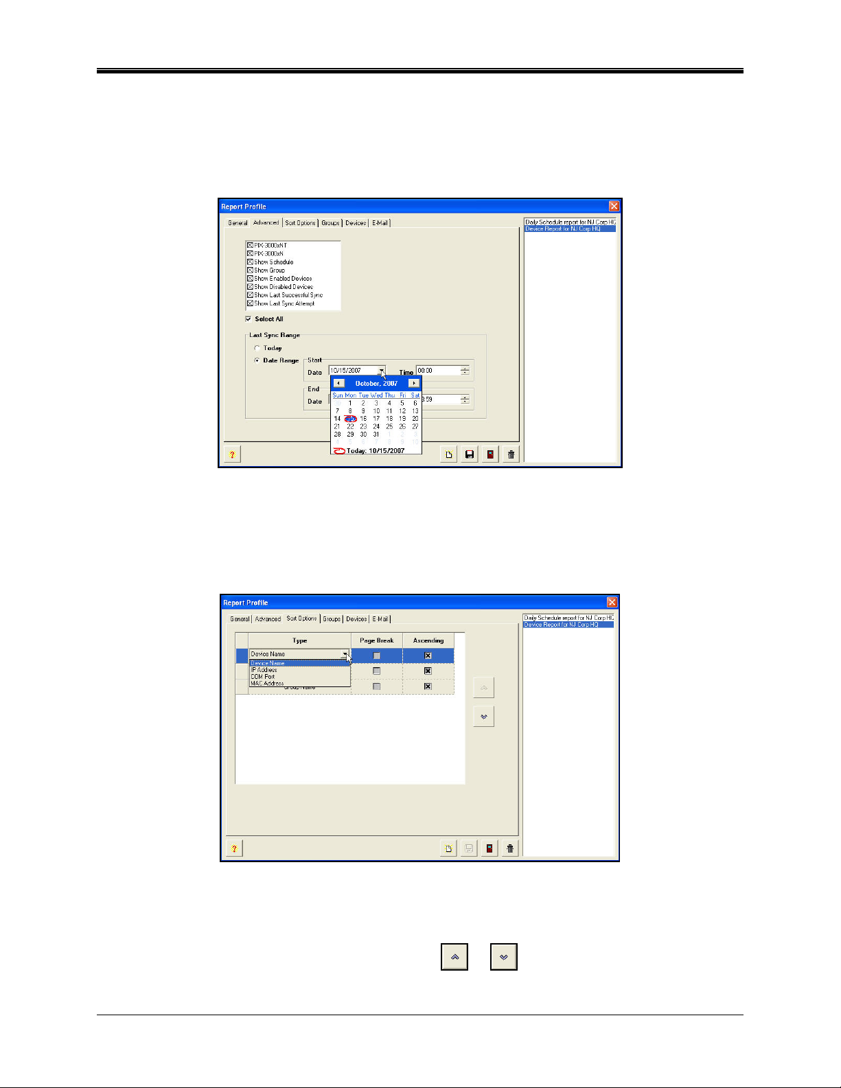
3. Enter a Name, and select the report Type from the dropdown list. The report type choices
are; Device, Schedule, Time Server, Transaction, or Status.
4. The Description field allows the user to type comments or remarks about the report. Click
on the Advanced tab, and the screen will appear as shown in Figure 120.
Note: The Advanced tab selections will vary depending on the report type selected.
Figure 120. Report Profile Advanced Tab
5. Individually select the desired item(s) to show, or click on Select All.
6. Define the Last Sync Range by clicking on Today, or Date Range. Then click on the Sort
Options tab, and the screen will appear as shown in Figure 121.
Figure 121. Report Profile Sort Options Tab
7. Define the sort/filter options by clicking on Device Name and selecting from the dropdown
list: Device Name, IP Address, Com Port, or MAC Address. Also, define the sequence report
filter order by selecting a type and using the up
or down move arrows. Then click
on the Groups tab, and the screen will appear as shown in Figure 122.
5-2 ATVS Enterprise Edition v4.2 Installation & Operation Guide
Page 73

Note: The Sort Options tab will not be present for Status, and Transaction Reports.
Figure 122. Report Profile Groups Tab
8. If desired, from the Available list (default status for Groups previously defined), select the
Group(s) by using the selection arrows (
or ) to move them to the Selected list on
the right from the Available list on the left.
Note: This tab will not be present for Schedule, Time Server, and Transaction Reports.
9. Then click on the Devices tab, and the screen will appear as shown in Figure 123. If
desired, from the Selected list (default status for devices previously defined), deselect the
Device(s) by using the selection arrows (
"Selected" list on the right to the "Available" list on the left.
Note: The devices will be automatically selected once the Groups are selected in the previous
step.
This tab will not be present for Schedule, Time Server, and Transaction Reports.
or ) to move them from the default
Figure 123. Report Profile Devices Tab
ATVS Enterprise Edition v4.2 Installation & Operation Guide 5-3
Page 74

10. Then click on the E-Mail tab, and the screen will appear as shown in . If desired, from the
Available list (default status for E-Mail accounts previously defined), select the E-Mail To by
using the selection arrows (
or ) to move them to the "Selected" list on the right
from the "Available" list on the left.
Figure 124. Report Profile E-Mail Tab
Use the Select E-Mail button to choose an e-mail address for the E-Mail From address (see
Figure 125).
Figure 125. Selecting E-Mail Account
11. When finished with defining the report profile, click on the Save button to save your
report profile settings and return to the Reports screen. Click on the Close
button to
quit without saving. The new Report Profile information will be displayed to the right of the
tree view list (see ).
5-4 ATVS Enterprise Edition v4.2 Installation & Operation Guide
Page 75
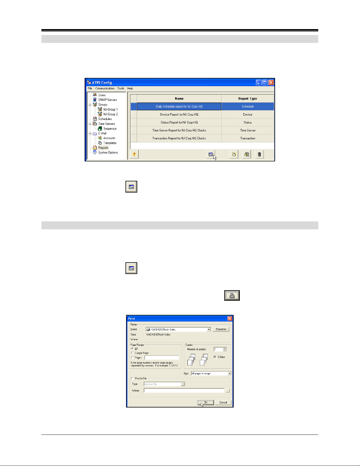
How To Run a Report
1. Click on the Reports icon in the tree view, and all previously defined Reports will appear.
2. Select a report from the list on the right by clicking on it to highlight the desired report (see
Figure 126).
3. Click on the Run Report button and the report will be created and/or formatted based
upon the previously defined report/filter criteria. See later in this chapter for descriptions of
the five available report types.
Figure 126. Selecting an ATVS Report
How To Print a Report
1. Click on the Reports icon in the tree view, and all previously defined Reports will appear.
2. Select a report from the list on the right by clicking on it to highlight the desired report (see
Figure 126).
3. Click on the Run Report
upon the previously defined report/filter criteria. See later in this chapter for descriptions of
the five available report types.
4. From the top of the report screen, click on the Print Report
print dialog screen will appear (see Figure 127).
button and the report will be created and/or formatted based
button, and the Windows
Figure 127. Windows Print Dialog
ATVS Enterprise Edition v4.2 Installation & Operation Guide 5-5
Page 76

How To Create a Report File
Follow the preceding procedure for printing a report.
1. When the Windows Print dialog window appears (see Figure 127) click Print to File (see
Figure 128).
Figure 128. Select File Type
2. Select the desired Format from the dropdown list. The report format choices are; PDF,
Word (RTF for Word), Excel, or Image.
3. Click on the Browse
button to select the file destination, and the Save As dialog will
appear (see Figure 129).
Figure 129. Windows Save As Dialog
4. Enter a file name, select a file type, and click on the Save button. The Print dialog screen
will appear again. Click on the Ok button and the file will be created in the defined
destination.
5-6 ATVS Enterprise Edition v4.2 Installation & Operation Guide
Page 77

How To Delete a Report Profile
1. Click on the Reports icon in the tree view, and all previously defined Reports will appear.
2. Select a report from the list on the right by clicking on it to highlight the desired report.
3. Click on the Delete
button. A confirmation dialog message for deletion will appear, and
click Yes to confirm deletion.
How To Modify a Report Profile
1. Select a Report from the list, and double-click on it, or click on the Edit button.
2. Type in the new information for the Report Profile and click on the Save button. The
redefined Report Profile will be displayed in the tree view list.
How To Navigate a Report
To navigate through any generated report use the Zoom In/Zoom Out ( ) buttons
and/or First/Previous/Next/Last Page
To print a generated report use the Print Report
example. Reports will be generated (formatted) based upon the filter criteria selected in the Sort
Options of the report profile.
To quit a generated report use the Close
screen.
buttons.
button. See Figure 130 for a report
button and return back to the reports list
Reports will be generated (formatted) based upon the filter criteria selected in the Sort Options
of the report profile.
Device Report
To generate a report, select a device report from the reports list and click on the Run Report
button. This report can be sorted by Device Name, IP Address, or Com Port. If desired, this
report can be formatted with page breaks, and in ascending order. Figure 130 is an example of
a displayed Device Report.
ATVS Enterprise Edition v4.2 Installation & Operation Guide 5-7
Page 78
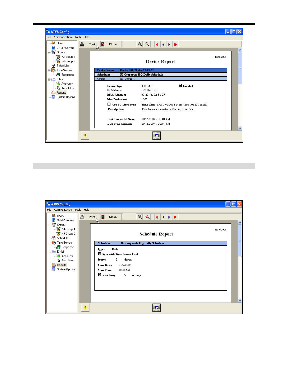
Figure 130. Device Report Example
Schedule Report
This report displays the Device Synchronization Schedules. This report can be generated for the
following schedule types: Daily, Weekly, Monthly, or Yearly. This report can be formatted with or
without page breaks, and in ascending/descending order. Figure 131 is an example of a
displayed Schedule Report.
Figure 131. Schedule Report Example
5-8 ATVS Enterprise Edition v4.2 Installation & Operation Guide
Page 79

Time Server Report
When selected, this option will generate a report containing any or all the time sources, NTP
servers and dial-up services, in the database. This report can show the following server types:
NIST, NTP, NPL, PTB, Enabled, Disabled, last successful sync, and/or last sync attempt. A
report can be generated for today or a date range with starting and ending date and time.
This report can be formatted with or without page breaks, and in ascending/descending order.
Additional sorting/filtering can be performed by: Time Server Name, IP Address/Host Name,
Telephone Number, and Com Port. Figure 132 is an example of a displayed Time Server
Report.
Figure 132. Time Server Report Example
Transaction Report
The Transaction Log Report is used to generate a report of a log based on a specific date
(today) or a date range (Log Report) with a starting and ending date and time. Figure 133 is an
example of a displayed Transaction Report.
Figure 133. Transaction Report Example
ATVS Enterprise Edition v4.2 Installation & Operation Guide 5-9
Page 80
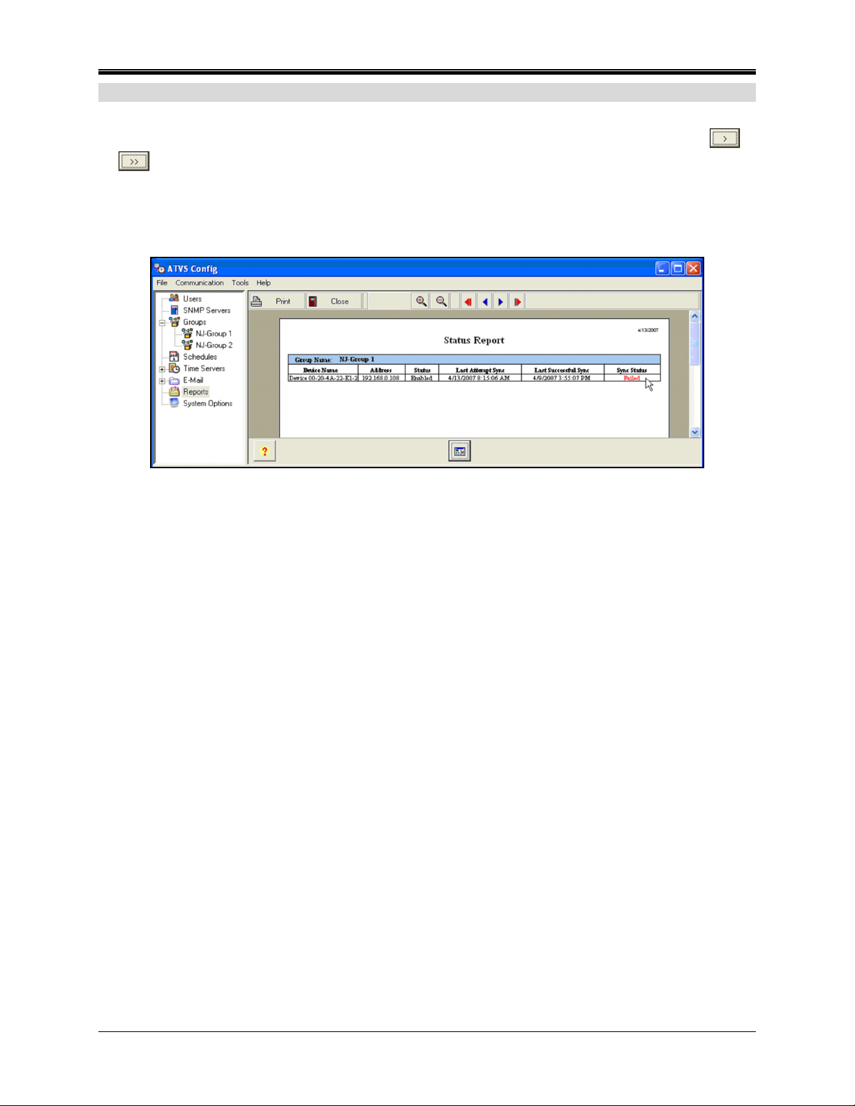
Status Report
A Status Report is a simple way of checking the status of each Device in your system. To
generate a report, select a group or groups from the Available Events list and click on the
or
buttons to move them to the Selected Events list. The choices for events are: failed to
sync with the time server, failed to communicate with the clock, and successful synchronization.
Select the Groups to run the report(s) for, and the Devices assigned to those Groups will
automatically be selected. Figure 134 is an example of a displayed Status Report.
Figure 134. Status Report Example
Note: In a report, if a Device had failed synchronization, the word “Failed” will be in the Sync
Status column in red.
5-10 ATVS Enterprise Edition v4.2 Installation & Operation Guide
Page 81
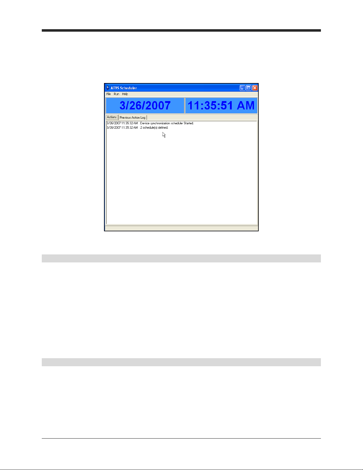
Chapter 6: Action Log Messages
Unless otherwise specified, the messages listed will appear in the status section when either a
Actions or Previous Actions Log is selected. To see these messages startup the ATVS
Scheduler. Figure 135 is an example of the ATVS Scheduler.
Figure 135. ATVS Scheduler
Startup and Shut Down Messages
Initialize Initiated...
Date Time: Device synchronization scheduler started.
xxx Actions Scheduled
Date Time: Number of schedules defined.
Action List [xxx]. Time = MM/DD/YYYY hh:mm:ss message1, message2
Date Time: Attempting to run schedule.
Initialize Succeeded.
Configuration initialization completed.
Network Time Synchronization Messages
Trying to connect to server #xx
Where xx is the Server Name. ATVS is attempting to connect to the specified NTP
server.
Time From Server #xx
Where xx is the Server Name. ATVS received time information from the specified NTP
server.
ATVS Enterprise Edition v4.2 Installation & Operation Guide 6-1
Page 82

Deviation From Time Server xx = HH:MM:SS.SSS
Where xx is the Server Name and HH:MM:SS.SSS is the time deviation between the
ATVS Host and the NTP server. When the time is received from the NTP server, it is
compared with the ATVS Host. If the difference between the two is greater than the
Maximum Deviation, the NTP server time is considered incorrect.
Connecting to IP Address XXX.XXX.XXX.XXXX
Where XXX.XXX.XXX.XXX is the IP Address. ATVS is in-process of connecting to the
specified NTP server. (Detailed Activity Logging only)
Connected to server xx NNN
Where xx is the Server Name and NNN is the server name. ATVS has successfully
connected to the specified NTP server. (Detailed Activity Logging only)
Attempting to synchronize to the Time Server(s): Retry #xx.
Where xx is the number of retry. No time data was received from seven out of ten NTP
servers in the first time through the cycle.
Could not resolve server xx host Server Location: XXX.XXX.XXX.XXXX
Where xx is the Server Name and XXX.XXX.XXX.XXX is the IP Address or Host Name.
The IP Address entered for the NTP server is incorrect, or the DNS translation option is
not enabled. (Detailed Activity Logging only)
Could not receive information from server xx, XXX.XXX.XXX.XXXX
Where xx is the Server Name and XXX.XXX.XXX.XXX is the IP Address or Host Name.
No time data was received from the NTP server. The system will attempt to make five
connections until successful. (Detailed Activity Logging only)
Deviation Error From Time Server :xx
Where xx is the Server Name. When the time is received from the NTP server, it is
compared with the ATVS Host. If the difference between the two is greater than the
Maximum Deviation, the NTP server time is considered incorrect.
Failed to sync due to Timeout Error from Time Server : xx
Where xx is the Server Name. No connection was established with the NTP server due
to a network or server failure.
Failed to sync due to Invalid Host from Time Server xx
Where xx is the Server Name. The IP Address entered for the NTP server is incorrect, or
the DNS translation option is not enabled.
Did not receive enough data from Time Server xx, XXX.XXX.XXX.XXXX
Where xx is the Server Name and XXX.XXX.XXX.XXX is the IP Address or Host Name.
No time data was received from the NTP server. The system will attempt to make five
connections until successful.
6-2 ATVS Enterprise Edition v4.2 Installation & Operation Guide
Page 83

NIST ACTS Messages
Preparing to dial out
The system is initializing modem to dial NIST.
Dialing
The system is dialing the NIST telephone number.
Connection established
Connection between ATVS Host and NIST succeeded.
Time from XXXXX : MM/DD/YYYY hh:mm:ss:nnn
NIST time/date data successfully received from ACTS.
Deviation from XXXXX = hh:mm:ss:nnn
Time difference between ATVS Host and ACTS.
Redialing
Redialing NIST telephone number.
The configured device is not functioning
The Com port does not exist or is invalid on this system.
The configured modem connection is invalid
The Com port the modem is set to is not functioning.
Could not receive correct information
Connection was established but ATVS did not receive correct information. System will
automatically redial to NIST in five minutes.
Could not communicate with modem
Modem may not be connected, powered on or it is not responding to the application.
Could not connect to XXXXX modem
Could not connect to specified modem.
PIX Transmission Messages
Starting Communication
Device synchronization initiated.
Transmitting time and date to pix Name : XXXXXXX (xxx.xxx.xxx.xxx)
Transmitting time and date to Device via IP Address xxx.xxx.xxx.xxx.
Successfully sync time to Device: XXXXXXX (xxx.xxx.xxx.xxx) Est. Latency = xxx (ms)
or
Successfully sync time to Device: XXXXXXX via Com X
Where X is the Com Port #. Where XXXXXXX is the Device Name, xxx.xxx.xxx.xxx is its
IP Address, xxxx is the Estimated Latency of the network and x is the Com Port number.
Synchronization with the Device was successful.
ATVS Enterprise Edition v4.2 Installation & Operation Guide 6-3
Page 84

Failed to communicate with Device XXXXXXX (xxx.xxx.xxx.xxx)
Where XXXXXXX is the Device Name and its IP Address is xxx.xxx.xxx.xxx. This occurs
when the IP Address entered for the specified Device does not exist, is incorrect, or the
Device is not functioning.
Connection request timed out
No connection was established between the ATVS Host and the specified Device due to
an invalid IP address, network failure, or the Device is not functioning.
Send timed out
The IP Address entered for the specified Device does not exist, incorrect, or the Device
is not functioning.
Transmitting time and date to pix xx x
Where x is the Com Port number, and xx is the Device Name.
Send Succeeded COMx
(Look on previous page for send succeeded for Com Port).
Where x is the Com Port number. Broadcast to Com Port x was successful.
Failed to sync time to Device xxxxxxx via Com x.
Where x is the Com Port number and xxxxxxx is the Device Name. Broadcast to Com
Port X has failed, and XXXXXXX is Device Name.
The configured RS-485 connection is invalid
The Device attached to the system is not functioning.
Invalid Com Port setting. The Com Port does not exist on the system or it cannot be
open.
The Device attached to the system is not functioning
The IP Address entered for the specified Device is incorrect, does not exist, incorrect, or
the Device is not functioning.
Connection request timed out
No connection was established between the ATVS Host and the specified Device due to
an invalid IP address, network failure, or the Device is not functioning.
Winsock Error Code: xxxx: XXXXXXXX
Where xxxx is the Winsock Error Code and XXXXXXXX is the Winsock Error. Typically,
this error will occur if there is a wiring problem or the Device is not functioning.
General and Other Messages
Successfully sent E-mail : x
E-mail was successfully sent by recipient. x is E-mail template name.
Failed to send E-mail : x
The ATVS Host was unable to send e-mail. x is E-mail template name.
6-4 ATVS Enterprise Edition v4.2 Installation & Operation Guide
Page 85

Troubleshooting
The basic guidelines for troubleshooting error or failure messages are as follows:
• Check all electrical connections, and verify that all computer ports and Devices are properly
configured and functioning.
• Verify that the specified IP/Mac Addresses are entered correctly and enabled.
• Consult the PIX-3000x Operation Manual for more details on clock operation.
ATVS Enterprise Edition v4.2 Installation & Operation Guide 6-5
Page 86

This page intentionally left blank.
6-6 ATVS Enterprise Edition v4.2 Installation & Operation Guide
Page 87

Page 88

AJR-401201 z Copyright © 2007 Amano Cincinnati, Inc. z 10/07/0
 Loading...