

Page 1
4700/4800 Series
Time Stamp
Handling Manual
Page 2

Proprietary Notice
This document contains proprietary information and such information
may not be reproduced in whole or part without the written permission
from Amano Cincinnati, Inc. 140 Harrison Ave., Roseland, New Jersey
07068.
Amano Cincinnati, Inc. reserves the right to make equipment changes
and improvements, which may not be reflected in this document.
Portions of this document may have been updated to include the latest
hardware or firmware version, if applicable. We recommend that this
document be read in its entirety before any attempt is made to operate
the equipment.
Thank You….
For purchasing another fine product from
Amano Cincinnati, Inc.
Page 3

Table of Contents
Table of Contents.................................................................i
Introduction .........................................................................1
Preparation Before Use ......................................................1
How To Take Off The Case.................................................1
How To Operate ..................................................................2
How To Set The Typewheels..............................................2
How To Set The Clock ........................................................3
How To Change A Ribbon ..................................................5
Adjustment of Printing Position ........................................6
Printing Sample ..................................................................... 8
Caution On Use ...................................................................9
For Power Reserve Type Only ...........................................9
4700/4800 Series Time Stamp Operation Manual i
Page 4

ii 4700/4800 Series Time Stamp Operation Manual
Page 5
Introduction
This manual explains how to use your 4700/4800 Series Time Stamp.
You are strongly encouraged to read this manual completely
using the 4700/4800 Time Stamp, and to retain it for future reference.
before
Preparation Before Use
(Refer to Fig. 1, 2, & 7)
To prevent possible damage of the machine during transit, shock
absorbing material has been put inside the machine body (hammer
section).
Prior to use, take off the case, lift up the clock and typewheel sections,
and then remove the packaging material under the ink ribbon.
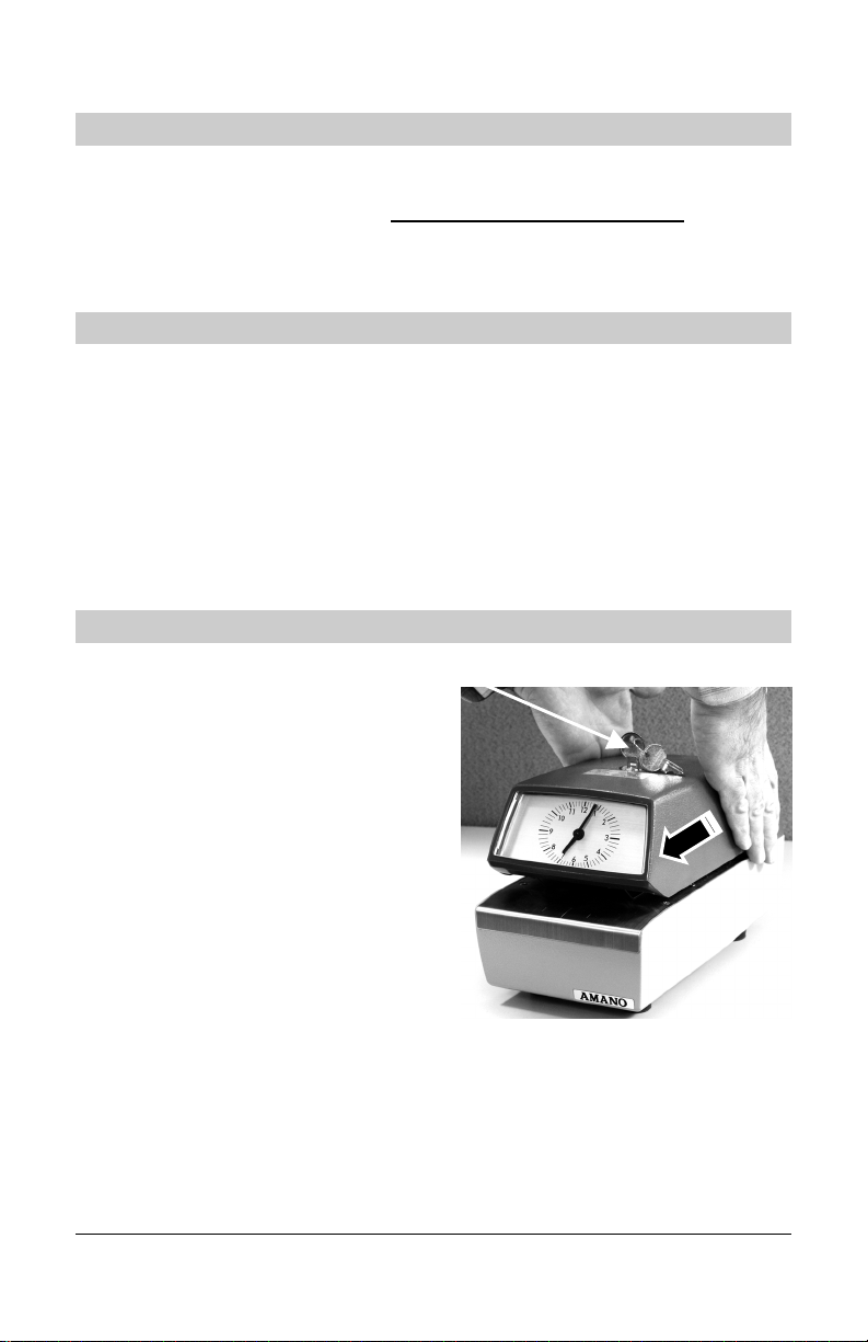
How To Take Off The Case
(Refer to Fig. 1)
To take off the case, insert the key
into the key lock on the upper case,
and turn it. Holding the case with
both hands (see Figure 1), draw it
frontward a little and then lift it up.
Key
Caution: When removing the case,
please pay attention not to
touch the clock hands!
4700/4800 Series Time Stamp Operation Manual 1
Figure 1.
Page 6

g
Shaft Holde
Shaft
How To Operate
• Connect the power cord to an electrical power source.
• Insert the papers along the guide line of slide plate for automatic
printing (about 5 sheets, if back carboned slips, can be copied).
How To Set The Typewheels
(Refer to Fig. 2, 3, & 5)
• Remove the case, and turn the shaft holder [1] in the arrow
direction indicated in Figure 2 to detach it from the shaft [2].
• Next pull out the shaft [2] in the arrow direction indicated in
Figure 2, and set up the typewheel and clock sections as shown
in Figure 3.
r 1
2
Clock Face
To Set the 4700 Series (Year, Month, Date, Time)
2 4700/4800 Series Time Stamp Operation Manual
Fi
ure 2.
• Keeping the electrical cord to A.C. main, push the minute
advance lever [5] as shown in Figure 5, in the arrow direction,
then turn the typewheels [3] for year, month, date, hour and
minute in the direction of the arrow shown in Figure 3 and set
one minute before the desired time.
Page 7

• On releasing the minute advance lever [5], the minute
typewheel advances one minute to synchronize with the desired
time.
Clock Face
Typewheels 3
Figure 3.
To Set the 4800 Series
Model 4850 …4 digit numbers (Year, Month, Date, Hours & Minute)
Model 4850 …5 digit numbers )Month, Date, Hours & Minute)
• The numbers will be changed automatically upon each printing.
• To set the desired number, operate the number wheel advance
lever [14] as illustrated in Figure 5.
Caution: When setting the typewheel by the minute advance lever [5],
right after the cam dropped the cam follower to advance one
minute, the typewheel can not be moved by hand and so, wait
for about 15 seconds, and then repeat the operation!
How To Set The Clock
(Refer to Fig. 4 & 5)
• Turn the clock advance gear [4] to set the clock.
Caution: The clock advance gear can be turned in either the right or left
direction!
• To set the typewheel and clock hands to the same time, first set
the typewheel to the desired time, then set the clock by turning
the clock advance gear [4] to the time of the typewheel until a
tick sound is heard.
4700/4800 Series Time Stamp Operation Manual 3
Page 8

• To advance the typewheel and clock at the same time, push the
minute advance lever [5] (see Figure 5) in the arrow direction,
so the typewheel and clock hand advance one minute at the
same time.
Caution: The setting of the typewheel should be done only right after
the minute typewheel is advanced!
Clock Advance
Gear
4
Figure 4.
Clock Face
Figure 5.
4 4700/4800 Series Time Stamp Operation Manual
Page 9

How To Change A Ribbon
(Refer to Fig. 6 & 7)
• In case the print color becomes too light, or the ribbon is cut or
crumpled too much, please replace the ribbon with a new one.
• First check whether the ribbon reverse turn lever [6] (see Figure
6) is inclined to the inner side of the machine. Incase the lever is
inclined to the front, push it in the direction of the inner side.
• Wind the whole ribbon onto the ribbon spool [7] located in the
front of the machine, then remove the ribbon with the spool from
the machine.
• Install a new ribbon with spool [7] on the machine. Then wind the
ribbon on the ribbon spool [8] through the outside ribbon guide
shaft [9], and fix with the ribbon fixer [10].
• Wind the ribbon on the ribbon spool [8] until the slack ribbon
disappears, and pull the ribbon reverse lever [6] front wards.
Figure 6.
4700/4800 Series Time Stamp Operation Manual 5
Page 10

Figure 7.
Adjustment of Printing Position
(Refer to Fig. 8, 9 & 10)
Ribbon
Spool
8
Ribbon
Fixer
Ribbon
Guide Shaft
9
Ribbon
Spool
7
• The printing position can be adjusted by moving the knob [11]
(see Figures 8 & 9) between 37 mm – 83 mm (1.5” – 3.25”) from
the top of the paper. When the upper die plate hammer is taken
out, the printing position can be within 16 mm – 83 mm (.66” –
3.25”) from the top of the paper.
• For easy setting of the printing position, refer to the mark on the
side plate.
• Incase the printing position is to be fixed, tighten the screw [12]
(see Figure 9), and remove the knob [11].
• Incase the upper die plate is installed, please make sure the
screw [13] is tightened. Remove the screw [13] if the upper die
plate is not equipped.
6 4700/4800 Series Time Stamp Operation Manual
Page 11

Knob for
printing
adjustment
11
Figure 8.
Figure 9.
4700/4800 Series Time Stamp Operation Manual 7
Page 12

Printing Sample
Figure 10.
Incase the printing is required on paper
narrower than 65 mm (2 5/8”), install the
polyester sheet supplied as accessory
in between the bottom case and slide
plate as per illustration by placing the
sheet so as the edge cut side comes to
the right-hand side.
A is a portion of the polyester sheet
circled by dot line that has to be cut by
scissors or knife, incase the upper die
plate is not installed and the inner
printing hammer is removed to have the
printing on the very upper edge of the
paper.
8 4700/4800 Series Time Stamp Operation Manual
Page 13

Caution On Use
• DO NOT touch the clock hands in any case.
• When the printing color becomes light, replace the ribbon with a
new one. DO NOT paint with stamping ink as this could injure
the machine.
• When cleaning the typewheel, carefully remove the dust lodged
between the typewheels.
For Power Reserve Type Only
(Refer to Fig. 11)
1. For Quartz Clock with power reserve type.
• After setting the clock and typewheel, plug the connector (see
Figure 11) together so that the clock and typewheel start to
advance.
• The time can be set even to the second by pushing 00 second
setting button on the terminal board mounting plate (see Figure
11).
Figure 11.
2. For D.C. impulse driven hour correction type
• Clock advance gear can only be turned clockwise.
4700/4800 Series Time Stamp Operation Manual 9
Page 14

NOTES
10 4700/4800 Series Time Stamp Operation Manual
Page 15

Page 16

© Copyright 2006 11/06/0
 Loading...