

Page 1
Installation
Instructions
Electric Range
ImportantSave for local electrical inspectors use.
Keep instructions for future reference.
Be sure manual stays with range.
Read entire instruction before beginning installation.
Read Owners Manual for safe installation.
TM
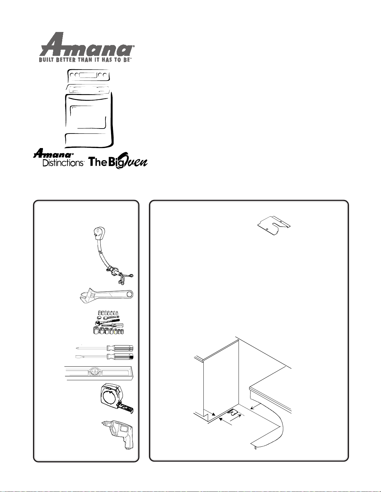
Youll Need a Few
Things Before You
Begin
Power Cord
(3-wire or 4-wire)
and Strain Relief
Wrench
3
/8" Nut Driver
or Sockets
Screw
Drivers
Level
Tape Measure
PREPARE TO
INSTALL RANGE
1
AND INSTALL
ANTI-TIP
BRACKET
Measure cabinet area and prepare it
according to illustrations in Minimum
Clearances to Combustible
Surfaces and Range and Cabinet
Dimensions section in this manual.
Remove the packing materials and
locate the anti-tip bracket, screws,
plastic anchors and anti-tip bracket
installation instructions.
Anti-tip
bracket can
be installed
on either
side of
range.
Anti-tip
Bracket
Installation
To reduce risk of range tipping,
sercure range with a properly
installed anti-tip bracket. Refer to
anti-tip bracket installation
instructions. Do not proceed
with installation until this step
has been completed.
Once anti-tip bracket has been
installed, proceed to the next
step of the installation.
Drill and DrillBit
3
/32" for wood floor
3
/16" for concrete floor
"
3 1/
3
"
/
16
2
Page 2
CONNECT
ELECTRICAL
2
CORD
To place electrical receptacle, see
Electrical Receptacle Location
diagram in this manual.
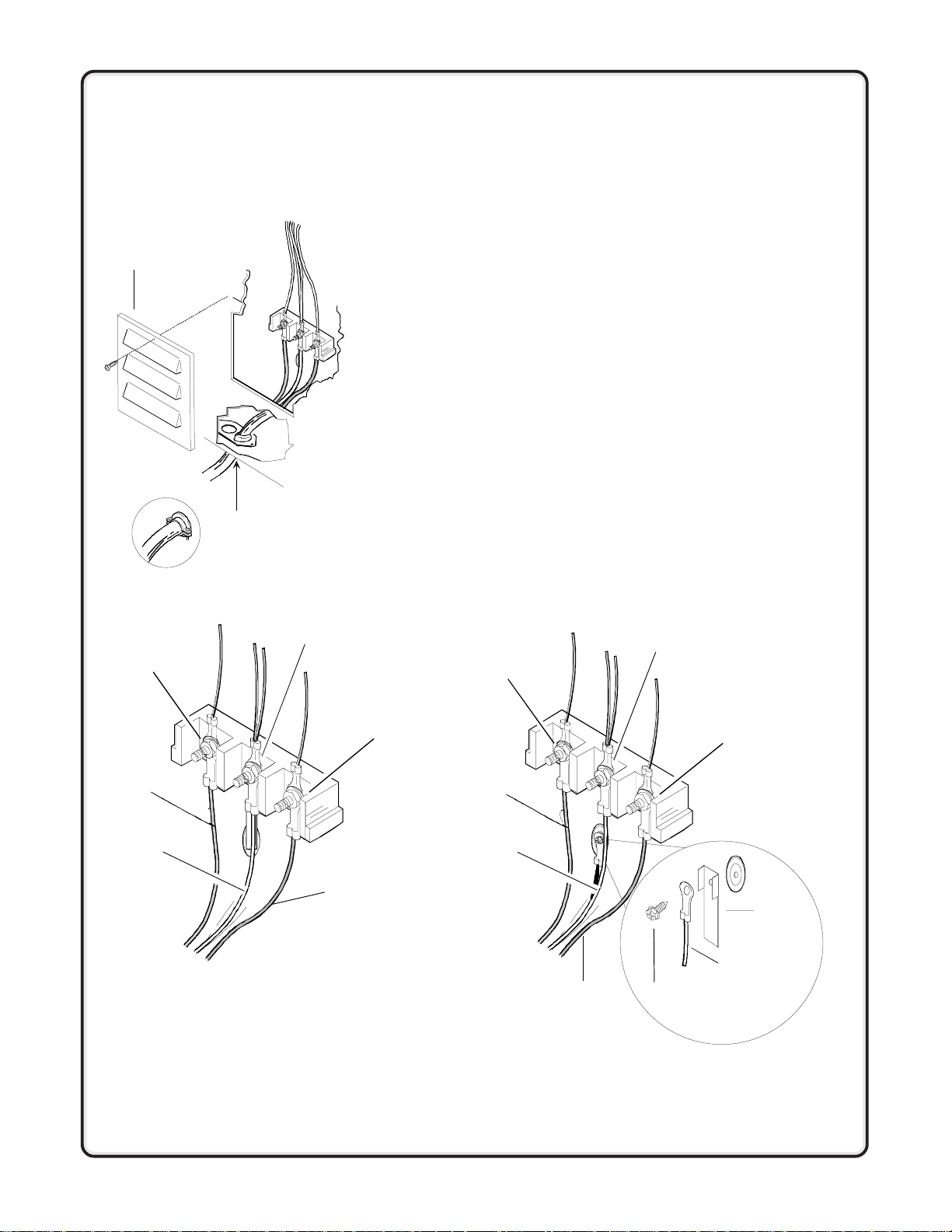
Range has been grounded at the factory to the center (nickel plated) terminal
of the terminal block in accordance with the National Electric Code. When a
separate ground is required by local code, disconnect the grounding strap
from the terminal block. Ground frame by connecting a grounding wire to
range frame using the grounding strap and screw, as shown below, removed
from the grounding strap.
Access
cover
"L1"
Strain relief
(not supplied with range)
Neutral
3-wire or 4-wire Plug Connection
Four-wire cord is required for mobile homes or where codes (Canada) do not
permit grounding through neutral.
1. Remove access cover from rear of range.
2. Use a strain relief (not supplied) and insert end of power cord (not
supplied) through power supply hole.
3. 4-wire Plug OnlyRemove the green ground screw from range back.
Remove both the hex nuts and the grounding strap from the center
terminal. Position grounding strap down and away from terminal block.
Replace 1 hex nut on the center terminal. Attach the power cord ground
wire (green or bare) and grounding strap to rear bulkhead using ground
screw.
4. Unscrew and use top hex nut to attach the power cord wires to the
terminal block as follows:
Red wire to L1 terminal.
Black wire to L2 terminal.
White wire to Neutral terminal.
5. Tighten all hex nuts and reinstall access cover removed in step 1.
4-wire Cord Installed3-wire Cord Installed
Neutral
"L1"
"L2"
Red
White
Black
Converting 3-Wire to 4-Wire Power Cord
1. Remove access cover from rear of range.
2. Remove bottom strain relief screw and retain for further use.
3. Remove hex nuts from terminal block and retain for further use.
4. Remove all 3-wire or cable leads from the terminal block and proceed to
remove the power cord from the range by pulling in a downward motion
so the cord is removed from strain relief.
5. To install the 4-wire cord, follow the 4-wire instructions shown above.
Red
White
Black
Ground
screw
"L2"
Ground
strap
Ground
wire
Page 3

POSITION AND
3
LEVEL RANGE
Place range near final position and
plug in. Then, slide range into final
position and adjust all legs (4) until
range is level side to side and front to
back.
Place a level on top oven rack or
on range top when leveling.
Leveling legs must extend ¼" to
engage anti-tip bracket.
Remove
Storage
Drawer and
Check Anti-tip
Bracket
After range is in position,
remove storage drawer or lower panel
and confirm anti-tip bracket is
engaged with range leveling leg.
To remove storage drawer
1. Slide drawer out until it stops.
2. Grasp drawer sides near back of
drawer.
3. Lift up and out. Reverse to
reinstall.
To avoid
damaging oven
door, do not lift or
move range by
oven door handle.
Glass can break.
Removal and Replacement of Range
1. Disconnect power to range.
2. Slide range forward.
3. Unplug range cord and place range aside.
4. Remove anti-tip bracket.
5. Install anti-tip bracket into new location using instructions provided
with bracket or see Anti-tip Bracket installation section in this
manual.
6. To reinstall range, follow instructions in this manual.
Questions?
See Owners Manual or call Amana
Consumer Affairs Department
1-800-843-0304
Page 4

IMPORTANT SAFETY INFORMATION
WARNING
!
To avoid risk of burns or fire by
reaching over elements, cabinet
storage space located above
range should be avoided. If
cabinet storage is provided,
install a range hood that projects
horizontally a minimum of 5"
beyond the cabinet bottom to
reduce the risk.
WARNING
!
To avoid risk of electrical shock,
personal injury, or death, make
sure your range has been
properly grounded and always
disconnect it from main power
supply before servicing.
WARNING
!
To avoid risk of the appliance tipping, it must be secured by a
properly installed anti-tip bracket. To make sure bracket has been
installed properly, remove the storage drawer or panel and look
under the range with a flashlight. Bracket must be engaged in the
rear corner of the range.
ALL RANGES CAN TIP
INJURY TO PERSONS
COULD RESULT
INSTALL ANTI-TIP
BRACKET(S) PACKED
WITH RANGE
SEE INSTALLATION
INSTRUCTIONS
Minimum Clearances to Combustible Surfaces
This range can be installed flush against right and left base
cabinets, and rear vertical wall. Range can also be installed
flush against left or right vertical wall extending above 36"
standard countertop height. The dimensions provided are
to be measured from the range itself, and not the
installation cutout for the range.
AMinimum of 30" between top of cooking surface and
bottom of an unprotected wood or metal cabinet.
OR
AMinimum of 24" between cooking surface and wood or
metal cabinet bottom protected by not less than ¼ thick
flame retardant millboard covered with not less than No. 28
MSG sheet steel, .015 inch thick stainless steel, .024 inch
thick aluminum, or .020 inch thick copper.
BMinimum of 30" of protected cabinets above the range
(refer to letter A)
CMinimum of 18 between top of countertop and bottom of
an unprotected wood or metal cabinet.
DMaximum depth of 13 for overcounter cabinets.
C
B
A
D
Part No. 36-32055801-0
Printed in U.S.A. 03/01
SAVE THESE INSTRUCTIONS
2001 Amana Appliances
Amana, Iowa 52204
Page 5

ü
Installation Requirements
Consider Description
Before You Install
Location
Electrical Requirements Electrical Supply
This range can be installed flush against right and left base cabinets, and rear
vertical wall. Range can also be installed flush against left or right vertical wall
extending above 36" standard countertop height.
Use dimensions shown in this manual to determine space needed for
installatio n.
Range must not be installed or stored in an area where it will be exposed to
water and/or weather. Range is heavy and must not be installed on soft flooring
such as cushioned vinyl or carpeting. If this type of flooring is present where the
range will sit, ¼" thick sheet of plywood or similar material should be placed
where the range will be installed.
Irregular Cabinet and Countertop Heights
Countertops such as ceramic tile tops cause cabinet and countertop to be higher
than 36". Follow instructions below when countertop is higher than 36".
1. Raise leveling legs to maximum height.
2. Measure from floor to rangetop. If the height of the range is less than height
of countertop, floor must be shimmed.
3. Shim floor using a piece of plywood same size as range opening. Secure
plywood to floor. Plywood must be as secure as original flooring.
4. Install anti-tip bracket and slide range into place.
Range needs a 3 or 4 wire 240 Volt AC, 40 amp, 60 Hertz, 1 Phase electrical
supply. W iring system and grounding must conform with the latest edition of the
National Electric Code, ANSI/NFPA 70, or the Canadian Electrical Code, CSA
C22.1. Installation must conform to all local, municipal and state building codes,
and local utility regulations. Connect range to power supply with MAXIMUM
RATED VOLTAGE listed on the rating plate. Line voltage must not exceed rated
voltage.
Copper Wire
Terminal block is approved for copper wire connection only. If aluminum house
wiring is to be connected to the cooktop, use only connectors designed for
joining copper to aluminum and follow the manufacturers recommended
procedure closely. The following procedure is suggested:
1. Connect length of copper building wire to range terminal block with ring
term inals.
2. Splice copper wires to aluminum wiring using connectors that are design
certified by Underwriters Laboratories and recognized for joining copper to
aluminum. Follow the connector manufacturers recommended procedure.
3. W ire used, location and enclosure of splices must conform to local codes.
Pow er Cord
Power cord is not supplied with range. Power cord must be U.L. or C.S.A. listed
and meet NEC and Mobile Home Manufacturers Association Standards. Cord
must be rated at a minimum 250V40 AMP, equipped with a plug configuration
in accordance with NEMA. Conductors must end with closed loop (ring)
terminals at the range.
Three-conductor cord plug NEMA 10-50P allowed for residential in U.S.
Four-conductor cord plug NEMA 14-50P required in Canada and for most
mobile home installations, but can be used for residential.
NOTE: Only a power cord suitable for use with ranges may be used.
For installation in a mobile home, or area where local codes (Canada)
do not permit grounding through the neutral terminal, a 4-wire cord
must be used.
Page 6

Range and Cabinet Dimensions
25"
36"
30"
28 1/4"
25 1/2"
24"
46 1/2"
36"
30 1/8"
Electrical Receptacle Location
Locate electrical receptacle in area with diagonal lines.
30 1/8"
3"
24 1/8"
5"
3"
3"
2 1/2"
3"
 Loading...