

Page 1
R
LTO
OWNER'S MANUAL
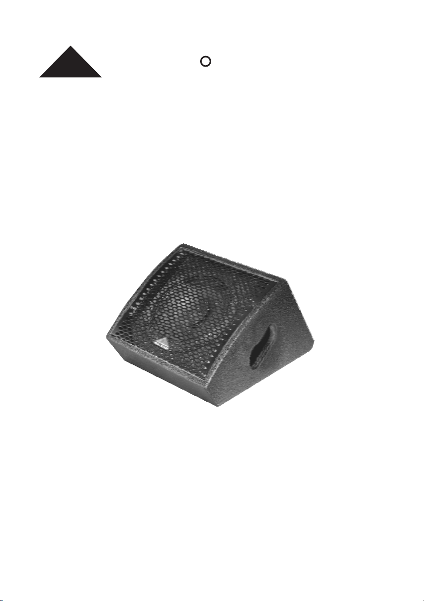
MS MONITOR SPEAKER ENCLOSURES
ACTIVE MODELS
www.altoproaudio.com
Version 1.1 SEPTEMBER 2007
English
Page 2
IMPORTANT SAFETY INSTRUCTION
CAUTION
RISK OFELECTRIC SHOCK
DO NOTOPEN
TO REDUCE THE RISK OF ELECTRIC SHOCK
PLEASE DO NOT REMOVE THE COVER OR
THE BACK PANEL OF THIS EQUIPMENT.
THERE ARE NO PARTS NEEDED BY USER
INSIDE THE EQUIPMENT. FOR SERVICE,
PLEASE CONTACT QUALIFIED SERVICE
CENTERS.
This symbol, wherever used, alerts you to the
presence of un-insulated and dangerous voltages
within the product enclosure. These are voltages that
may be sufficient to constitute the risk of electric
shock or death.
This symbol, wherever used, alerts you to
important operating and maintenance instructions.
Please read.
Protective Ground Terminal
AC mains (Alternating Current)
Hazardous Live Terminal
ON: Denotes the product is turned on.
OFF: Denotes the product is turned off.
CAUTION
Describes precautions that should be observed to
prevent damage to the product.
1.
Read this Manual carefully before operation.
Keep this Manual in a safe place.
2.
Be aware of all warnings reported
3.
with this symbol.
4.
Keep this Equipment away from water and
moisture.
5.
Clean it only with dry cloth. Do not use
solvent or other chemicals.
6.
Do not damp or cover any cooling opening.
Install the equipment only in accordance with
the Manufacturer's instructions.
Power Cords are designed for your safety. Do
7.
not remove Ground connections! If the plug
does not fit your AC outlet, seek advice from
a qualified electrician. Protect the power
cord and plug from any physical stress to
avoid risk of electric shock. Do not place
heavy objects on the power cord. This could
cause electric shock or fire.
Unplug this equipment when unused for long
8.
periods of time or during a storm.
Refer all service to qualified service personnel
9.
only. Do not perform any servicing other than
those instructions contained within the
User's Manual.
To prevent fire and damage to the product,
10.
use only the recommended fuse type as
indicated in this manual. Do not short-circuit
the fuse holder. Before replacing the fuse,
make sure that the product is OFF and
disconnected from the AC outlet.
WARNING
To reduce the risk of electric shock
and fire, do not expose this equipment
to moisture or rain.
Dispose of this product should
notbeplacedinmunicipalwaste
and should be separate collection.
MovethisEquipmentonlywithacart,
11.
stand, tripod, or bracket,
specified by the
manufacturer, or
sold with the
Equipment. When
a cart is used, use
caution when
moving the cart /
equipment
combination to
avoid possible
injury from tip-over.
12.
Permanent hearing loss may be caused by
exposure to \ extremely high noise levels.
The US. Government's Occupational Safety
and Health Administration (OSHA) has
specified the permissible exposure to noise
level.
These are shown in the following chart:
HOURS X DAY
8
6
4
3
2
1,5
1
0,5
0,25 or less
According to OSHA, an exposure to high SPL in
excess of these limits may result in the loss of
heat. To avoid the potential damage of heat, it is
recommended that Personnel exposed to
equipment capable of generating high SPL use
hearing protection while such equipment is
under operation.
The apparatus shall be connected to a mains
socket outlet with a protective earthing
connection.
The mains plug or an appliance coupler is used
as the disconnect device, the disconnect device
shall remain readily operable.
EXAMPLE
SPL
Small gig
90
train
92
Subway train
95
High level desktop monitors
97
Classic music concert
100
102
105
110
115
Rock concert
Page 3
IN THIS MANUAL:
1. INTRODUCTION................................................................................. 1
2. FEATURES.........................................................................................2
3.. APPLICATIONS.................................................................................. 2
4. PANEL DESCRIPTION......................................................................... 4
5. WIRE CONNECTIONS......................................................................... 6
6. FREQUENCY RESPONSE DIAGRAM..................................................... 7
7. TECHNICAL SPECIFICATION................................................................ 8
8. WARRANTY ...................................................................................... 9
1. INTRODUCTION
Thank you very much for expressing your confidence in LTO products by
purchasing MS series powered monitor speaker system. The MS series monitor
are specifically designed for using in hi-quality performance site and the precise
sound commercial place. It includes three small and compact stage monitor
models (MS8MA, MS10MA, MS12MA) This series uses trapezium configuration
which greatly decreases the resonance of the standing wave in the cabinet.
These cabinets uses hi-density matrix spray-paint technics and the bottom
bracket design which make mounting quickly and flexibly. HF compression driver
and vented LF for fully professional performance.
The MS powered monitor speaker cabinets include some exclusive innovations
such as switch mode power supply and digital power circuitry (in selected modes)
that make them the lightest powered cabinets of this kind ever made. The MS
full range models include another Alto innovation: The MODELLER. Thanks to this
circuitry user can select 16 different tastes and applications.
MS powered Monitor speakerEnjoy your and make sure to read this Manual
carefully before operation!
1
Page 4

2. FEATURES
The excellent quality of MS series-powered monitor speaker cabinets will provide
the following features:
Small and compact stage monitor
Trapezium configuration decreases the resonance of the standing wave in the
cabinet
Using hi-density matrix spray-paint technics for the cabinets
The bottom bracket design makes mounting quickly and flexibly
HF compression driver and vented LF for fully professional performance
With modeller include have 16 "sound mode " which are suitable for different
tastes and applications
Switch mode power supply and digital power circuitry
HOOK
UP
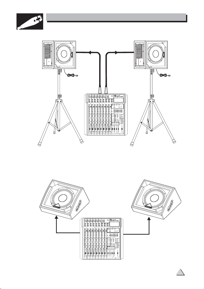
Make all initial connections with all the equipment powered off, and ensure that
all the main volume controls are turned down completely.
1). Connect one side of the signal cable at your mixer into the Main Output Left
/Right (with 1/4"Jack or XLR) and the other side of the cable in to the Line
Input (COMBO) of your MS monitor speaker cabinet (with1/4"Jack or XLR).
2). Connect the power cord to mains.
3). Turn ON your mixer first, then the MS cabinets.
4). Turn up the volume control of the MS cabinets.
5). Use PFL function to get the proper input level for the mixer, and adjust the
Main Mix Level control to reach the desired output level.
6). After use, turn off your active speaker cabinets first, then the mixer.
3. APPLICATIONS
2
Page 5
HOOK
3. APPLICATIONS
UP
For MS Monitors with stand
Tripod
Mount
Signal Cable
Power Cord
Left
Main Mix
Output
MIXER
For MS Monitors on the floor
Signal Cable
Right
Main Mix
Output
Power Cord
Tripod
Mount
LINE IN
MAIN OUT LEFT
LINE IN
MAIN OUT RIGHT
MIXER
3
Page 6

SPOTLIGHT
4. PANEL DESCRIPTION
POWERED MONITOR: MS8MA/MS10MA/MS12MA
(3)
(6)
(7)
(5)
(4)
(8)
(9)
(1)
(7)
(6)
NEW TIDE
POWER
DRUMFILL+SUB
GUITAR2
GUITAR1
STAGE
BOOM
TWIN
SIDEFILL
ANTIFEEDBACK
PIANO
LOUDNESS
FULLRANGE+SUB
ENTERTAINER
VOCAL2
ROCK& ROLL
VOCAL1
FLAT
VOLUME
132
INPUT
MIN MAX
SIGNAL
LINK
LIMIT
BAL
ON
OFF
AC INPUT
LTO
POWER
Useonly with a 250V fuse
220-240V~50/60Hz
FUSE:T1.5AL 250V
(2)
R
MS8MA
"WARNING"
TOREDUCE THE RISK OF FIRE OR
ELECTRICSHOCK DO NOT EXPOSE THISPRODUCT
TORAIN OR MOISTURE.
MODELSERIAL
(5)
POWER
(9)
(3)
(8)
(4)
JAZZCLUB+SUB
VOLUME
ACOUSTIC
ROCK& ROLL+SUB
NEW TIDE
132
INPUT
LINK
BAL
LOUDNESS
ARENA+SUB
CONCERTHALL
ANTIRUMBLE
MIN MAX
DRUMKICK
SIGNAL
LIMIT
FLAT
VIRTUALSUB
ROCK& ROLL
STAGEMONITOR
JAZZCLUB
DISCO
VOCAL
CONCERTHALL+SUB
AC INPUT
R
(1)
ON OFF
POWER
Useonlywith a 250V fuse
220-240V~50/60Hz
FUSE:T3.15AL 250V
(2)
LTO
MS12MA
MODEL
SERIAL
TOREDUCE THE RISK OF FIRE OR ELECTRICSHOCK DO NOT EXPOSE THIS PRODUCT TO RAIN OR MOISTURE.
"WARNING"
(1) main power switchON-OFF
(2) Input with main fuseAC power socket
(3) main power amplifier controlVOLUME
(4) at +4 dB on XLR connectorLINE OUT
(5) at +4 dB on COMBO connectorLINE IN
(6) SwitchGround
(7) , Green LED, indicate ON statusPOWER
(8) , Red LED, indicate ON statusSIGNAL LIMIT
(9) SelectorPresets
Via this knob, you can select the right effect you wish to perform.
There are totally 16 options for you:
4
Page 7

SPOTLIGHT
4. PANEL DESCRIPTION
1. FLAT: This is the "default" MODEL. The frequency response is typical of floor
monitor. This Model suits all the applications where reproduction of the
whole audio content is required.
2. VOCAL 1: This Model is similar to FLAT model but includes a High-pass Filter
to cut out the selected low frequencies. It is advisable to use this
preset for human voice reproduction. Especially male voice. Also very
good for speech.
3. VOCAL 2: It is similar to VOCAL 1, but we have added a Low-pass Filter to
remove the selected high-frequencies. In this way, all the acoustic
content is dedicated to the Middle frequencies to get the best possible
reproduction of the human voice for stage monitor applications.
4. GUITAR 1: This Model has been optimized for electric guitar monitoring. But
it can also be used directly connected to a Guitar Preamplifier making
use of digital effects, modelling, ect, both in MONO and in STEREO
systems.
5. GUITAR 2: This model is great for Acoustic Guitar. The booming frequencies
of the hollow body guitar are taken away while a gentle crispy touch is
added to compensate lack of high frequencies reproduction from the
pick up. Try it with your Acoustic guitar directly connected to the Input
and you will not need a dedicate amplifier anymore.
6. PIANO: This model has been created for effective monitor of acoustic piano
but it is also suitable for other keyboards such as Rhodes, the Wurlitzer
and it is also good with Hammond style sounds.
7. DRUMFILL+ SUB: In this case we have provided this model with a sharp
high-pass filter so that your MS monitor can be used together with a
subwoofer in DRUMFILL systems.
8. TWIN: In this Model we have created a low-cut and high-frequencies enhance
-ment with the goal of optimizing the frequency response of the MS
Monitor when more than one unit are used together.
9. STAGE: Very often Stage Monitors are positioned on suspended floor made
of wood or metal. This Model prevent the nasty resonance on low
frequency produced by such positioning.
10. BOOM: This model must be used when the monitor is positioned on a
microphone Boom for near-field monitoring.
11. SIDEFILL: To be used with MS Monitor in sidefill position.
12. ANTIFEEDBACK: With this Model the frequencies that are responsible for
feedback are reduced sharply.
13. LOUDNESS: It generates the typical "happy face" curve. To be used with
prolonged listening at low SPL.
5
Page 8

SPOTLIGHT
4. PANEL DESCRIPTION
14. FULL RANGE + SUB: Made to reduce distortion and moving coil overheating
to reduce power compression when the cabinet is used in conjunction
with a subwoofer.
15. ENTERTAINER: This Model has been thought for Piano Bar Players and
Entertaining Musicians using digital keyboard and microphones together
with karaoke and MP3 devices. You get a crispy sound on the high
frequencies and a gentle peak on low frequencies so that you do not need
a lot of external equalization.
16. ROCK & ROLL: Made for maximum dynamic range without compromising
amplifier headroom and speaker power handling.
HOOK
5. WIRE CONNECTIONS
UP
-. For Active Speaker Cabinets
As to these circumstances, audio connections is mostly intended for the signal flow,
so, determine the wire configuration according to your real application system and
its connecting facility. Normally, you have the following choices:
Balanced
Tip
TIP RINGSLEEVE
1
3
2
TIP RINGSLEEVE
Unbalanced
TIP RINGSLEEVE
TIP SLEEVE
TIP SLEEVE
TIP RINGSLEEVE
1
3
2
SLEEVE RINGTIP
1
3
2
1
3
2
1
3
2
1
3
2
SLEEVE TIP
SLEEVE RINGTIP
1
3
2
Ring
Sleeve
Ring
Sleeve
Ring
Sleeve
Sleeve
Sleeve
Ring
Sleeve
1
2
3
Tip
Tip
Tip
Tip
Tip
1
2
3
Tip
Ring
Sleeve
1
2
3
1
2
3
1
2
3
1
2
3
Tip
Sleeve
Tip
Ring
Sleeve
1
2
3
6
Page 9

6. FREQUENCY RESPONSE DIAGRAM
MS8MA
+110
+100
d
B
+90
S
P
L
+80
+70
20 20k
+110
+100
d
B
+90
S
P
L
+80
100 200 500 1k 2k 5k 10k
50
Hz
MS10MA
+70
20
50
100 200 500 1k 2k 5k 10k
Hz
MS12MA
+110
+100
d
B
+90
S
P
L
+80
+70
20 20k
100 200 500 1k 2k 5k 10k
50
Hz
20k
7
Page 10

7. TECHNICAL SPECIFICATION
Model Item
Active System Type
Output Power
Peak Power
Max SPL 1mt
Frequency Response
Protection Low - High
Input Impedance
Input Sensitivity
Low Frequency Device
High Frequency Device
Coverage( H x V )
Connectors
Cabinet
External Control
Dimensions(HxWxD)
Net Weight (lbs/kg)
Model Item
Active System Type
Low Output Power
High output Power
Max SPL 1mt
Frequency Response
Protection Low - High
Input Impedance
Input Sensitivity
Low Frequency Device
High Frequency Device
Coverage( H x V )
Connectors
Cabinet
External Control
Dimensions(HxWxD)
Net Weight (lbs/kg)
Model Item
Active System Type
Low Output Power
High output Power
Max SPL 1mt
Frequency Response
Protection Low - High
Input Impedance
Input Sensitivity
Low Frequency Device
High Frequency Device
Coverage( H x V )
Connectors
Cabinet
External Control
Dimensions(HxWxD)
Net Weight (lbs / kg)
MS8MA
Full Range with MODELLER
100 Watt
150 Watt EIAJ
114 dB SPL Nominal/116 dB Peak
MODELLER Presets Setting
Analog Limiter
30 k Balanced/15 k Unbalanced
Line +4 dB
8" Dual Cone/1.5"Voice Coil
1" Neodymium Driver/1" Voice Coil
70 Hx70 V
Input with Combo/Link with XLR
Trapezoidal Shape/Multi-layer Plywood/Handle/Black Paint Finishing
MODELLER with 16 Presets/Line Volume/Clipping LED indicator
/Ground Switch
210 x 300 x 356 (mm)
16.98 lbs/7.7 kg
MS10MA
2-way Bi-Amp. With MODELLER
350 Watt EIAJ
65 Watt EIAJ
120 dB SPL Calculated EIAJ
MODELLER Presets Setting
Analog Limiter
30 k Balanced/15 k Unbalanced
Line +4 dB
10" Coax/2" Voice Coil
1" Neodymium Driver/1" Voice Coil
70 H x 70 V Spherical Horn
Input With Combo/Link With XLR
Trapezoidal Shape/Multi-layer Plywood/Handle/Black Paint Finishing
MODELLER with 16 Preset/Line Volume/Clipping LED indicator
/Ground Switch
273 x 362 x 454 (mm)
22.75 lbs/10.32 kg
MS12MA
2-Way Bi-Amp. with MODELLER
350 Watt EIAJ
65 Watt EIAJ
121 dB SPL Calculated EIAJ
MODELLER Presets Setting
Analog Limiter
30 k Balanced/15 k Unbalanced
Line +4 dB
12" Coax/2" Voice Coil
1" Neodymium Driver/1" Voice Coil
70 H x 70 V Spherical Horn
Input with Combo/Link with XLR
Trapezoidal Shape/Multi-layer Plywood/Handle/Black Paint Finishing
MODELLER with 16 Presets/Line Volume/Clipping LED Indicator
/Ground Switch
313 x 393 x 513 (mm)
26.12 lbs/11.85 kg
8
Page 11

8. WARRANTY
1. WARRANTY REGISTRATION CARD
To obtain Warranty Service, the buyer should first fill out and return the enclosed
Warranty Registration Card within 10 days of the Purchase Date.
All the information presented in this Warranty Registration Card gives the
manufacturer a better understanding of the sales status, so as to provide a
more effective and efficient after-sales warranty service. Please fill out all the
information carefully and genuinely, miswriting or absence of this card will void
your warranty service.
2. RETURN NOTICE
2.1 In case of return for any warranty service, please make sure that the
product is well packed in its original shipping carton, and it can protect your
unit from any other extra damage.
2.2 Please provide a copy of your sales receipt or other proof of purchase with
the returned machine, and give detail information about your return address
and contact telephone number.
2.3 A brief description of the defect will be appreciated.
2.4 Please prepay all the costs involved in the return shipping, handling and
insurance.
3. TERMS AND CONDITIONS
3.1 warrants that this product will be free from any defects in materials
LT O
and/or workmanship for a period of 1 year from the purchase date if you
have completed the Warranty Registration Card in time.
3.2 The warranty service is only available to the original consumer, who purchased
this product directly from the retail dealer, and it can not be transferred.
3.3 During the warranty service, may repair or replace this product at its
own option at no charge to you for parts or for labor in accordance with the
right side of this limited warranty.
3.4 This warranty does not apply to the damages to this product that occurred
as the following conditions:
Instead of operating in accordance with the user's manual thoroughly, any abuse
or misuse of this product.
Normal tear and wear.
The product has been altered or modified in any way.
Damage which may have been caused either directly or indirectly by another
product / force / etc.
Abnormal service or repairing by anyone other than the qualified personnel or
technician.
And in such cases, all the expenses will be charged to the buyer.
3.5 In no event shall be liable for any incidental or consequential damages.
Some states do not allow the exclusion or limitation of incidental or
consequential damages, so the above exclusion or limitation may not apply to
you.
3.6 This warranty gives you the specific rights, and these rights are compatible
with the state laws, you may also have other statutory rights that may vary
from state to state.
LT O
LT O
9
Page 12

NO. 1, Lane 17, Sec. 2, Han Shi West Road, Taichung 40151, Taiwan
SEIKAKU TECHNICAL GROUP LIMITED
http://www.altoproaudio.com Tel: 886-4-22313737
email: alto@altoproaudio.com Fax: 886-4-22346757
All rights reserved to ALTO. All features and content might be changed
without prior notice. Any photocopy, translation, or reproduction of part of this
manual without written permission is forbidden. Copyright 2007 Seikaku Group
c
NF02801-1.1
 Loading...