

Page 1

Floating-Point IP Cores User Guide
Subscribe
Send Feedback
UG-01058
2014.12.19
101 Innovation Drive
San Jose, CA 95134
www.altera.com
Page 2

TOC-2
Contents
About Floating-Point IP Cores...........................................................................1-1
List of Floating-Point IP Cores.................................................................................................................. 1-1
Installing and Licensing IP Cores..............................................................................................................1-2
Design Flow.................................................................................................................................................. 1-2
IP Catalog and Parameter Editor...................................................................................................1-3
Specifying IP Core Parameters and Options................................................................................1-4
Specifying IP Core Parameters and Options (Legacy Parameter Editors)...............................1-8
Upgrading IP Cores.....................................................................................................................................1-9
Migrating IP Cores to a Different Device...................................................................................1-12
Floating-Point IP Cores General Features..............................................................................................1-12
IEEE-754 Standard for Floating-Point Arithmetic............................................................................... 1-13
Floating-Point Formats.................................................................................................................1-13
Special Case Numbers...................................................................................................................1-14
Rounding.........................................................................................................................................1-15
Non-IEEE-754 Standard Format.............................................................................................................1-15
Floating-Points IP Cores Output Latency..............................................................................................1-16
Floating-Point IP Cores Design Example Files......................................................................................1-16
VHDL Component Declaration.............................................................................................................. 1-18
VHDL LIBRARY-USE Declaration.........................................................................................................1-18
ALTERA_FP_MATRIX_INV IP Core................................................................2-1
ALTERA_FP_MATRIX_INV Features....................................................................................................2-1
ALTERA_FP_MATRIX_INV Output Latency....................................................................................... 2-1
ALTERA_FP_MATRIX_INV Resource Utilization and Performance................................................2-1
ALTERA_FP_MATRIX_INV Functional Description..........................................................................2-2
Cholesky Decomposition Function...............................................................................................2-3
Triangular Matrix Inversion...........................................................................................................2-5
Matrix Multiplication......................................................................................................................2-5
Matrix Inversion Operation........................................................................................................... 2-5
ALTERA_FP_MATRIX_INV Design Example: Matrix Inverse of Single-Precision Format
Numbers.................................................................................................................................................. 2-6
ALTERA_FP_MATRIX_INV Design Example: Understanding the Simulation Results..... 2-7
Sample Matrix Data.....................................................................................................................................2-8
ALTERA_FP_MATRIX_INV Signals.....................................................................................................2-10
ALTERA_FP_MATRIX_INV Parameters.............................................................................................2-11
ALTERA_FP_MATRIX_MULT IP Core............................................................3-1
ALTERA_FP_MATRIX_MULT Features................................................................................................3-1
ALTERA_FP_MATRIX_MULT Output Latency...................................................................................3-1
ALTERA_FP_MATRIX_MULT Resource Utilization and Performance........................................... 3-1
ALTERA_FP_MATRIX_MULT Functional Description......................................................................3-2
Altera Corporation
Page 3

TOC-3
ALTERA_FP_MATRIX_MULT Signals.................................................................................................. 3-4
ALTERA_FP_MATRIX_MULT Parameters...........................................................................................3-5
ALTERA_FP_ACC_CUSTOM IP Core..............................................................4-1
ALTERA_FP_ACC_CUSTOM Features..................................................................................................4-1
ALTERA_FP_ACC_CUSTOM Output Latency.....................................................................................4-1
ALTERA_FP_ACC_CUSTOM Resource Utilization and Performance............................................. 4-1
ALTERA_FP_ACC_CUSTOM Signals.................................................................................................... 4-3
ALTERA_FP_ACC_CUSTOM Parameters.............................................................................................4-4
ALTFP_ADD_SUB IP Core................................................................................5-1
ALTFP_ADD_SUB Features......................................................................................................................5-1
ALTFP_ADD_SUB Output Latency.........................................................................................................5-1
ALTFP_ADD_SUB Truth Table................................................................................................................5-1
ALTFP_ADD_SUB Resource Utilization and Performance................................................................. 5-2
ALTFP_ADD_SUB Design Example: Addition of Double-Precision Format Numbers..................5-3
ALTFP_ADD_SUM Design Example: Understanding the Simulation Results......................5-3
ALTFP_ADD_SUB Signals........................................................................................................................ 5-4
ALTFP_ADD_SUB Parameters.................................................................................................................5-6
ALTFP_DIV IP Core...........................................................................................6-1
ALTFP_DIV Features..................................................................................................................................6-1
ALTFP_DIV Output Latency.....................................................................................................................6-1
ALTFP_DIV Truth Table........................................................................................................................... 6-2
ALTFP_DIV Resource Utilization and Performance.............................................................................6-3
ALTFP_DIV Design Example: Division of Single-Precision.................................................................6-4
ALTFP_DIV Design Example: Understanding the Simulation Results...................................6-4
ALTFP_DIV Signals....................................................................................................................................6-6
ALTFP_DIV Parameters.............................................................................................................................6-7
ALTFP_MULT IP Core....................................................................................... 7-1
ALTFP_MULT IP Core Features...............................................................................................................7-1
ALTFP_MULT Output Latency................................................................................................................ 7-1
ALTFP_MULT Truth Table.......................................................................................................................7-1
ALTFP_MULT Resource Utilization and Performance.........................................................................7-2
ALTFP_MULT Design Example: Multiplication of Double-Precision Format Numbers................7-3
ALTFP_MULT Design Example: Understanding the Simulation Waveform........................7-3
Parameters.....................................................................................................................................................7-4
ALTFP_MULT Signals................................................................................................................................7-5
ALTFP_SQRT......................................................................................................8-1
ALTFP_SQRT Features...............................................................................................................................8-1
Output Latency.............................................................................................................................................8-1
ALTFP_SQRT Truth Table........................................................................................................................ 8-2
ALTFP_SQRT Resource Utilization and Performance..........................................................................8-3
Altera Corporation
Page 4

TOC-4
ALTFP_SQRT Design Example: Square Root of Single-Precision Format Numbers........................8-3
ALTFP_SQRT Design Example: Understanding the Simulation Results................................8-3
ALTFP_SQRT Signals.................................................................................................................................8-4
ALTFP_SQRT Parameters..........................................................................................................................8-6
ALTFP_EXP IP Core...........................................................................................9-1
ALTFP_EXP Features..................................................................................................................................9-1
Output Latency.............................................................................................................................................9-1
ALTFP_EXP Truth Table........................................................................................................................... 9-1
ALTFP_EXP Resource Utilization and Performance.............................................................................9-2
ALTFP_EXP Design Example: Exponential of Single-Precision Format Numbers...........................9-2
ALTFP_EXP Design Example: Understanding the Simulation Results...................................9-3
ALTFP_EXP Signals....................................................................................................................................9-4
ALTFP_EXP Parameters.............................................................................................................................9-6
ALTFP_INV IP Core.........................................................................................10-1
ALTFP_INV Features............................................................................................................................... 10-1
Output Latency...........................................................................................................................................10-1
ALTFP_INV Truth Table.........................................................................................................................10-1
ALTFP_INV Resource Utilization and Performance...........................................................................10-2
ALTFP_INV Design Example: Inverse of Single-Precision Format Numbers ................................10-2
ALTFP_INV Design Example: Understanding the Simulation Results.................................10-3
Ports.............................................................................................................................................................10-4
Parameters.................................................................................................................................................. 10-5
ALTFP_INV_SQRT IP Core.............................................................................11-1
ALTFP_INV_SQRT Features...................................................................................................................11-1
Output Latency...........................................................................................................................................11-1
ALTFP_INV_SQRT Truth Table............................................................................................................11-1
ALTFP_INV_SQRT Resource Utilization and Performance..............................................................11-2
ALTFP_INV_SQRT Design Example: Inverse Square Root of Single-Precision Format
Numbers ...............................................................................................................................................11-2
ALTFP_INV_SQRT Design Example: Understanding the Simulation Results ...................11-3
Ports.............................................................................................................................................................11-4
Parameters.................................................................................................................................................. 11-5
ALTFP_LOG......................................................................................................12-1
ALTFP_LOG Features...............................................................................................................................12-1
Output Latency...........................................................................................................................................12-1
ALTFP_LOG Truth Table........................................................................................................................ 12-1
ALTFP_LOG Resource Utilization and Performance..........................................................................12-2
ALTFP_LOG Design Example: Natural Logarithm of Single-Precision Format Numbers ...........12-2
ALTFP_LOG Design Example: Understanding the Simulation Results................................12-3
Signals..........................................................................................................................................................12-4
Parameters.................................................................................................................................................. 12-6
Altera Corporation
Page 5

TOC-5
ALTFP_ATAN IP Core..................................................................................... 13-1
Output Latency...........................................................................................................................................13-1
ALTFP_ATAN Features........................................................................................................................... 13-1
ALTFP_ATAN Resource Utilization and Performance.......................................................................13-1
Ports.............................................................................................................................................................13-2
ALTFP_ATAN Parameters...................................................................................................................... 13-2
ALTFP_SINCOS IP Core.................................................................................. 14-1
ALTFP_SINCOS Features........................................................................................................................14-1
Output Latency...........................................................................................................................................14-1
ALTFP_SINCOS Resource Utilization and Performance....................................................................14-1
ALTFP_SINCOS Signals...........................................................................................................................14-2
ALTFP_SINCOS Parameters................................................................................................................... 14-3
ALTFP_ABS IP Core.........................................................................................15-1
ALTFP_ABS Features................................................................................................................................15-1
ALTFP_ABS Output Latency...................................................................................................................15-1
ALTFP_ABS Resource Utilization and Performance...........................................................................15-1
ALTFP_ABS Design Example: Absolute Value of Multiplication Results........................................ 15-2
ALTFP_ABS Design Example: Understanding the Simulation Results.................................15-2
ALTFP_ABS Signals..................................................................................................................................15-3
ALTFP_ABS Parameters...........................................................................................................................15-5
ALTFP_COMPARE IP Core.............................................................................16-1
ALTFP_COMPARE Features.................................................................................................................. 16-1
ALTFP_COMPARE Output Latency......................................................................................................16-1
ALTFP_COMPARE Resource Utilization and Performance..............................................................16-1
ALTFP_COMPARE Design Example: Comparison of Single-Precision Format Numbers...........16-2
ALTFP_COMPARE Design Example: Understanding the Simulation Results ...................16-2
ALTFP_COMPARE Signals.....................................................................................................................16-3
ALTFP_COMPARE Parameters..............................................................................................................16-4
ALTFP_CONVERT IP Core............................................................................. 17-1
ALTFP_CONVERT Features...................................................................................................................17-1
ALTFP_CONVERT Conversion Operations........................................................................................ 17-1
ALTFP_CONVERT Output Latency......................................................................................................17-2
ALTFP_CONVERT Resource Utilization and Performance.............................................................. 17-3
ALTFP_CONVERT Design Example: Convert Double-Precision Floating-Point Format
Numbers................................................................................................................................................17-6
ALTFP_CONVERT Design Example: Understanding the Simulation Results....................17-6
ALTFP_CONVERT Signals..................................................................................................................... 17-8
ALTFP_CONVERT Parameters............................................................................................................17-10
Altera Corporation
Page 6

TOC-6
ALTERA_FP_FUNCTIONS IP Core................................................................18-1
ALTERA_FP_FUNCTIONS Features.................................................................................................... 18-1
ALTERA_FP_FUNCTIONS Output Latency........................................................................................18-2
ALTERA_FP_FUNCTIONS Target Frequency....................................................................................18-2
ALTERA_FP_FUNCTIONS Combined Target....................................................................................18-2
ALTERA_FP_FUNCTIONS Resource Utilization and Performance................................................18-3
ALTERA_FP_FUNCTIONS Signals.....................................................................................................18-24
ALTERA_FP_FUNCTIONS Parameters............................................................................................. 18-25
Document Revision History...............................................................................A-1
Document Revision History......................................................................................................................A-1
Altera Corporation
Page 7

2014.12.19
www.altera.com
101 Innovation Drive, San Jose, CA 95134
About Floating-Point IP Cores
1
UG-01058
Subscribe
Send Feedback
The Altera® floating-point megafunction IP cores enable you to perform floating-point arithmetic in
FPGAs through optimized parameterizable functions for Altera device architectures.
You can customize the IP cores by configuring various parameters to accommodate your needs.
List of Floating-Point IP Cores
This table lists the Floating-Point IP cores.
Table 1-1: List of IP Cores
IP Core Name Function Overview
Operator Functions
ALTFP_ADD_SUB Adder/Subtractor
ALTFP_DIV Divider
ALTFP_MULT Multiplier
ALTFP_SQRT Square Root
Algebraic and Trancendental Functions
ALTFP_EXP Exponential
ALTFP_INV Inverse
ALTFP_INV_SQRT Inverse Square Root
ALTFP_LOG Natural Logarithm
Trigonometric Functions
ALTFP_ATAN Arctangent
ALTFP_SINCOS Trigonometric Sine/Cosine
Other Functions
ALTFP_ABS Absolute value
ALTFP_COMPARE Comparator
ALTFP_CONVERT Converter
©
2014 Altera Corporation. All rights reserved. ALTERA, ARRIA, CYCLONE, ENPIRION, MAX, MEGACORE, NIOS, QUARTUS and STRATIX words and logos are
trademarks of Altera Corporation and registered in the U.S. Patent and Trademark Office and in other countries. All other words and logos identified as
trademarks or service marks are the property of their respective holders as described at www.altera.com/common/legal.html. Altera warrants performance
of its semiconductor products to current specifications in accordance with Altera's standard warranty, but reserves the right to make changes to any
products and services at any time without notice. Altera assumes no responsibility or liability arising out of the application or use of any information,
product, or service described herein except as expressly agreed to in writing by Altera. Altera customers are advised to obtain the latest version of device
specifications before relying on any published information and before placing orders for products or services.
ISO
9001:2008
Registered
Page 8

acds
quartus - Contains the Quartus II software
ip - Contains the Altera IP Library and third-party IP cores
altera - Contains the Altera IP Library source code
<IP core name> - Contains the IP core source files
1-2
Installing and Licensing IP Cores
IP Core Name Function Overview
ALTERA_FP_ACC_CUSTOM An Application Specific Accumulator
ALTERA_FP_FUNCTIONS A Collection of Floating-Point Functions
Complex Functions
ALTFP_MATRIX_INV Matrix Inverse
ALTFP_MATRIX_MULT Matrix Multiplier
Related Information
Introduction to Altera IP Cores
Provides general information about Altera IP cores
Installing and Licensing IP Cores
The Altera IP Library provides many useful IP core functions for production use without purchasing an
additional license. You can evaluate any Altera® IP core in simulation and compilation in the Quartus® II
software using the OpenCore® evaluation feature. Some Altera IP cores, such as MegaCore® functions,
require that you purchase a separate license for production use. You can use the OpenCore Plus feature to
evaluate IP that requires purchase of an additional license until you are satisfied with the functionality and
performance. After you purchase a license, visit the Self Service Licensing Center to obtain a license
number for any Altera product.
UG-01058
2014.12.19
Figure 1-1: IP Core Installation Path
The default IP installation directory on Windows is <drive>:\altera\<version number>; on Linux it is
Note:
<home directory>/altera/ <version number>.
Related Information
• Altera Licensing Site
• Altera Software Installation and Licensing Manual
Design Flow
Use the IP Catalog and parameter editor to define and instantiate complex IP cores. Using the GUI
ensures that you set all IP core ports and parameters properly.
If you are an expert user, and choose to configure the IP core directly through parameterized instantiation
in your design, refer to the port and parameter details. The details of these ports and parameters are
hidden in the parameter editor.
Altera Corporation
About Floating-Point IP Cores
Send Feedback
Page 9
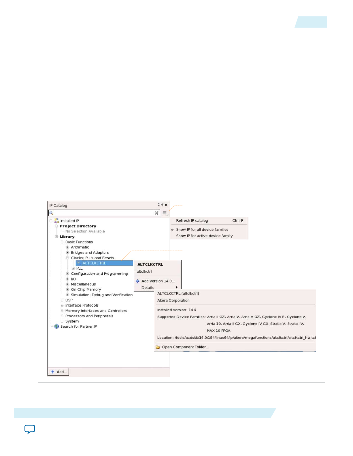
Search and filter IP for your target device
Double-click to customize, right-click for information
UG-01058
2014.12.19
IP Catalog and Parameter Editor
The Quartus II IP Catalog (Tools > IP Catalog) and parameter editor help you easily customize and
integrate IP cores into your project. You can use the IP Catalog and parameter editor to select, customize,
and generate files representing your custom IP variation.
Note: The IP Catalog (Tools > IP Catalog) and parameter editor replace the MegaWizard™ Plug-In
Manager for IP selection and parameterization, beginning in Quartus II software version 14.0. Use
the IP Catalog and parameter editor to locate and paramaterize Altera IP cores.
The IP Catalog lists IP cores available for your design. Double-click any IP core to launch the parameter
editor and generate files representing your IP variation. The parameter editor prompts you to specify an
IP variation name, optional ports, and output file generation options. The parameter editor generates a
top-level Qsys system file (.qsys) or Quartus II IP file (.qip) representing the IP core in your project. You
can also parameterize an IP variation without an open project.
Use the following features to help you quickly locate and select an IP core:
• Filter IP Catalog to Show IP for active device family or Show IP for all device families.
• Search to locate any full or partial IP core name in IP Catalog. Click Search for Partner IP, to access
partner IP information on the Altera website.
• Right-click an IP core name in IP Catalog to display details about supported devices, open the IP core's
installation folder, andor view links to documentation.
IP Catalog and Parameter Editor
1-3
Figure 1-2: Quartus II IP Catalog
The IP Catalog is also available in Qsys (View > IP Catalog). The Qsys IP Catalog includes
Note:
exclusive system interconnect, video and image processing, and other system-level IP that are not
About Floating-Point IP Cores
Send Feedback
Altera Corporation
Page 10
View IP port
and parameter
details
Apply preset parameters for
specific applications
Specify your IP variation name
and target device
Legacy parameter
editors
1-4
Using the Parameter Editor
available in the Quartus II IP Catalog. For more information about using the Qsys IP Catalog, refer
to Creating a System with Qsys in the Quartus II Handbook.
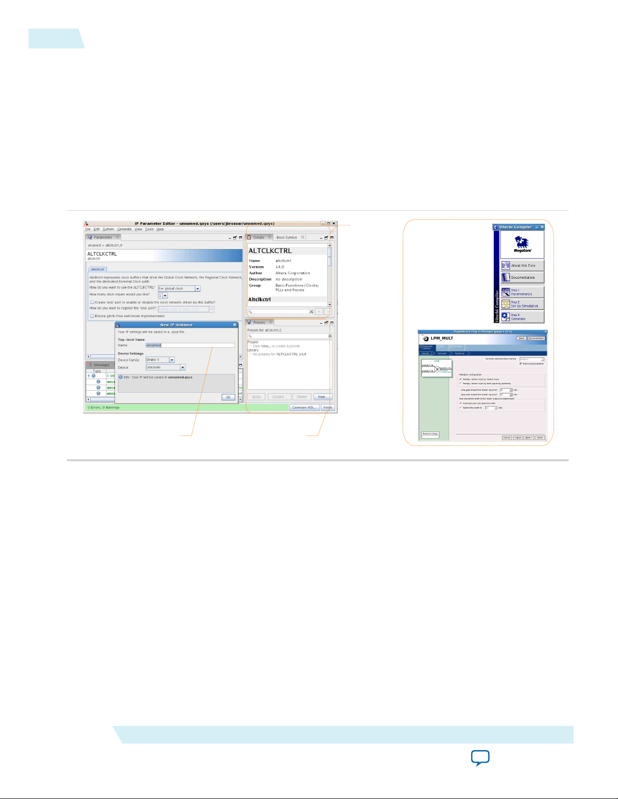
Using the Parameter Editor
The parameter editor helps you to configure IP core ports, parameters, and output file generation options.
• Use preset settings in the parameter editor (where provided) to instantly apply preset parameter values
for specific applications.
• View port and parameter descriptions, and links to documentation.
• Generate testbench systems or example designs (where provided).
Figure 1-3: IP Parameter Editors
UG-01058
2014.12.19
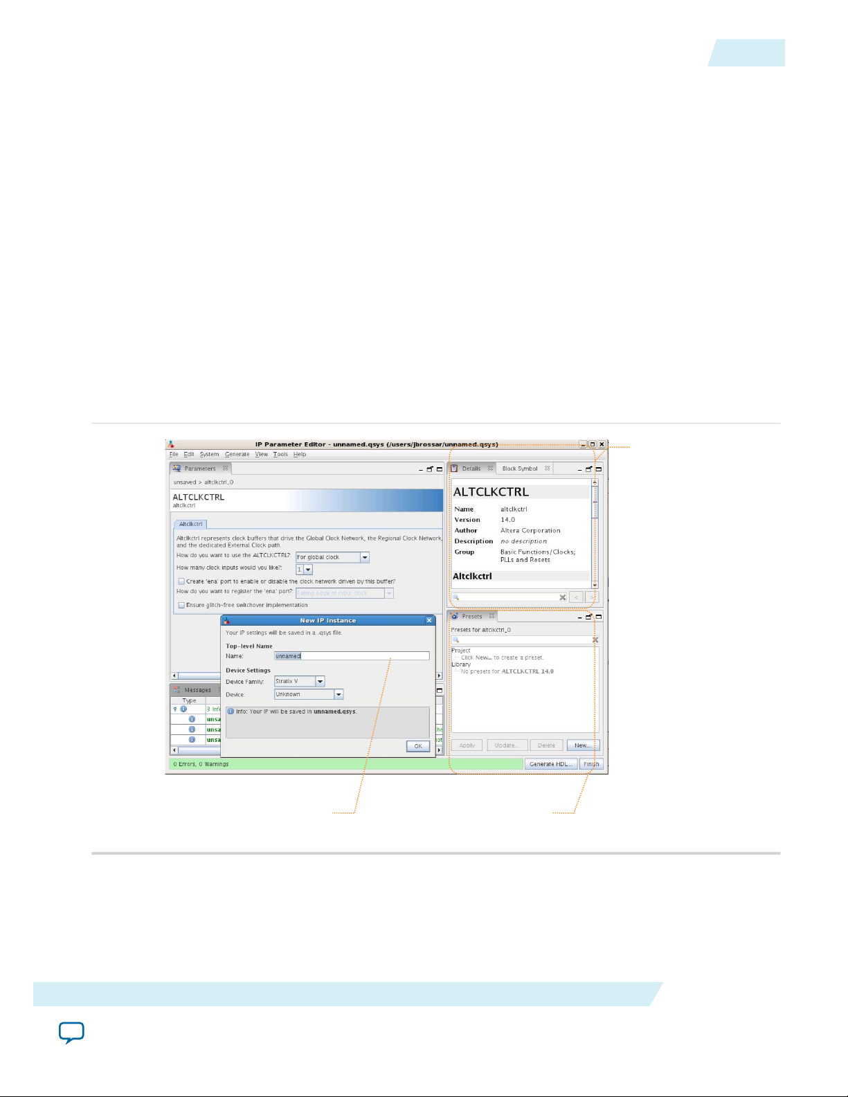
Specifying IP Core Parameters and Options
The parameter editor GUI allows you to quickly configure your custom IP variation. Use the following
steps to specify IP core options and parameters in the Quartus II software. Refer to Specifying IP Core
Parameters and Options (Legacy Parameter Editors) for configuration of IP cores using the legacy
parameter editor.
1. In the IP Catalog (Tools > IP Catalog), locate and double-click the name of the IP core to customize.
The parameter editor appears.
2. Specify a top-level name for your custom IP variation. The parameter editor saves the IP variation
settings in a file named <your_ip>.qsys. Click OK.
3. Specify the parameters and options for your IP variation in the parameter editor, including one or
more of the following. Refer to your IP core user guide for information about specific IP core
parameters.
Altera Corporation
About Floating-Point IP Cores
Send Feedback
Page 11
View IP port
and parameter
details
Apply preset parameters for
specific applications
Specify your IP variation name
and target device
UG-01058
2014.12.19
Files Generated for Altera IP Cores
• Optionally select preset parameter values if provided for your IP core. Presets specify initial
parameter values for specific applications.
• Specify parameters defining the IP core functionality, port configurations, and device-specific
features.
• Specify options for processing the IP core files in other EDA tools.
4. Click Generate HDL, the Generation dialog box appears.
5. Specify output file generation options, and then click Generate. The IP variation files generate
according to your specifications.
6. To generate a simulation testbench, click Generate > Generate Testbench System.
7. To generate an HDL instantiation template that you can copy and paste into your text editor, click
Generate > HDL Example.
8. Click Finish. The parameter editor adds the top-level .qsys file to the current project automatically. If
you are prompted to manually add the .qsys file to the project, click Project > Add/Remove Files in
Project to add the file.
9. After generating and instantiating your IP variation, make appropriate pin assignments to connect
ports.
Figure 1-4: IP Parameter Editor
1-5
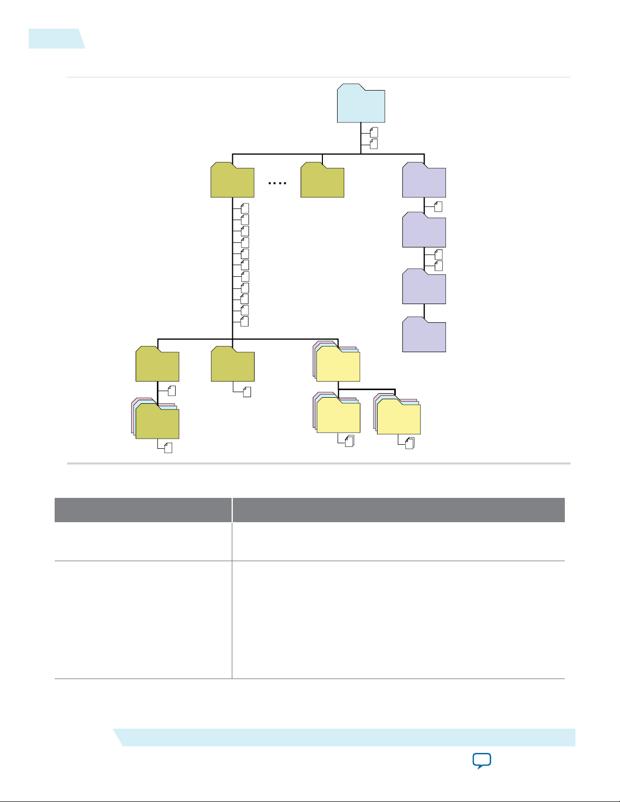
Files Generated for Altera IP Cores
The Quartus software generates the following IP core output file structure.
About Floating-Point IP Cores
Send Feedback
Altera Corporation
Page 12
<your_testbench>_tb.csv
<your_testbench>_tb.spd
<your_ip>.cmp - VHDL component declaration file
<your_ip>.ppf - XML I/O pin information file
<your_ip>.qip - Lists IP synthesis files
<your_ip>.sip - Lists files for simulation
<your_ip>.v or .vhd
Top-level IP synthesis file
<your_ip>.v or .vhd
Top-level simulation file
<simulator_setup_scripts>
<your_ip>.qsys - System or IP integration file
<your_ip>_bb.v - Verilog HDL black box EDA synthesis file
<your_ip>_inst.v or .vhd - Sample instantiation template
<your_ip>_generation.rpt - IP generation report
<your_ip>.debuginfo - Contains post-generation information
<your_ip>.html - Connection and memory map data
<your_ip>.bsf - Block symbol schematic
<your_ip>.spd - Combines individual simulation scripts
<your_ip>_tb.qsys
Testbench system file
<your_ip>.sopcinfo - Software tool-chain integration file
<project directory>
<EDA tool setup
scripts>
<your_ip>
IP variation files
<testbench>_tb
testbench system
sim
Simulation files
synth
IP synthesis files
sim
simulation files
<EDA tool name>
Simulator scripts
<testbench>_tb
<ip subcores> n
Subcore libraries
sim
Subcore
Simulation files
synth
Subcore
synthesis files
<HDL files>
<HDL files>
<your_ip> n
IP variation files
testbench files
1-6
Files Generated for Altera IP Cores
Figure 1-5: IP Core Generated Files
UG-01058
2014.12.19
Altera Corporation
Table 1-2: IP Core Generated Files
File Name Description
<my_ip>.qsys
<system>.sopcinfo Describes the connections and IP component parameterizations in
The Qsys system or top-level IP variation file. <my_ip> is the name
that you give your IP variation.
your Qsys system. You can parse its contents to get requirements
when you develop software drivers for IP components.
Downstream tools such as the Nios II tool chain use this file.
The .sopcinfo file and the system.h file generated for the Nios II tool
chain include address map information for each slave relative to each
master that accesses the slave. Different masters may have a different
address map to access a particular slave component.
About Floating-Point IP Cores
Send Feedback
Page 13

UG-01058
2014.12.19
Files Generated for Altera IP Cores
File Name Description
<my_ip>.cmp The VHDL Component Declaration (.cmp) file is a text file that
contains local generic and port definitions that you can use in VHDL
design files.
1-7
<my_ip>.html
A report that contains connection information, a memory map
showing the address of each slave with respect to each master to
which it is connected, and parameter assignments.
<my_ip>_generation.rpt IP or Qsys generation log file. A summary of the messages during IP
generation.
<my_ip>.debuginfo Contains post-generation information. Used to pass System Console
and Bus Analyzer Toolkit information about the Qsys interconnect.
The Bus Analysis Toolkit uses this file to identify debug components
in the Qsys interconnect.
<my_ip>.qip
Contains all the required information about the IP component to
integrate and compile the IP component in the Quartus software.
<my_ip>.csv Contains information about the upgrade status of the IP component.
<my_ip>.bsf A Block Symbol File (.bsf) representation of the IP variation for use
in Quartus Block Diagram Files (.bdf).
<my_ip>.spd
Required input file for ip-make-simscript to generate simulation
scripts for supported simulators. The .spd file contains a list of files
generated for simulation, along with information about memories
that you can initialize.
<my_ip>.ppf The Pin Planner File (.ppf) stores the port and node assignments for
IP components created for use with the Pin Planner.
<my_ip>_bb.v You can use the Verilog black-box (_bb.v) file as an empty module
declaration for use as a black box.
<my_ip>.sip Contains information required for NativeLink simulation of IP
components. You must add the .sip file to your Quartus project.
<my_ip>_inst.v or _inst.vhd HDL example instantiation template. You can copy and paste the
contents of this file into your HDL file to instantiate the IP variation.
<my_ip>.regmap If IP contains register information, .regmap file generates.
The .regmap file describes the register map information of master
and slave interfaces. This file complements the .sopcinfo file by
providing more detailed register information about the system. This
enables register display views and user customizable statistics in the
System Console.
About Floating-Point IP Cores
Send Feedback
Altera Corporation
Page 14

1-8
Specifying IP Core Parameters and Options (Legacy Parameter Editors)
File Name Description
UG-01058
2014.12.19
<my_ip>.svd
<my_ip>.v
or
<my_ip>.vhd
mentor/
aldec/
/synopsys/vcs
/synopsys/vcsmx
Allows HPS System Debug tools to view the register maps of
peripherals connected to HPS within a Qsys system.
During synthesis, the .svd files for slave interfaces visible to System
Console masters are stored in the .sof file in the debug section.
System Console reads this section, which Qsys can query for register
map information. For system slaves, Qsys can access the registers by
name.
HDL files that instantiate each submodule or child IP core for
synthesis or simulation.
Contains a ModelSim® script msim_setup.tcl to set up and run a
simulation.
Contains a Riviera-PRO script rivierapro_setup.tcl to setup and run a
simulation.
Contains a shell script vcs_setup.sh to set up and run a VCS
®
simulation.
Contains a shell script vcsmx_setup.sh and synopsys_ sim.setup file to
set up and run a VCS MX® simulation.
/cadence
Contains a shell script ncsim_setup.sh and other setup files to set up
and run an NCSIM simulation.
/submodules Contains HDL files for the IP core submodule.
<child IP cores>/ For each generated child IP core directory, Qsys generates /synth and /
sim sub-directories.
Specifying IP Core Parameters and Options (Legacy Parameter Editors)
Some IP cores use a legacy version of the parameter editor for configuration and generation. Use the
following steps to configure and generate an IP variation using a legacy parameter editor.
The legacy parameter editor generates a different output file structure than the latest parameter
Note:
editor. Refer to Specifying IP Core Parameters and Options for configuration of IP cores that use the
latest parameter editor.
Altera Corporation
About Floating-Point IP Cores
Send Feedback
Page 15

Legacy parameter
editors
UG-01058
2014.12.19
Figure 1-6: Legacy Parameter Editors
Upgrading IP Cores
1-9
1. In the IP Catalog (Tools > IP Catalog), locate and double-click the name of the IP core to customize.
The parameter editor appears.
2. Specify a top-level name and output HDL file type for your IP variation. This name identifies the IP
core variation files in your project. Click OK.
3. Specify the parameters and options for your IP variation in the parameter editor. Refer to your IP core
user guide for information about specific IP core parameters.
4. Click Finish or Generate (depending on the parameter editor version). The parameter editor generates
the files for your IP variation according to your specifications. Click Exit if prompted when generation
is complete. The parameter editor adds the top-level .qip file to the current project automatically.
Note:
Upgrading IP Cores
IP core variants generated with a previous version of the Quartus II software may require upgrading
before use in the current version of the Quartus II software. Click Project > Upgrade IP Components to
identify and upgrade IP core variants.
The Upgrade IP Components dialog box provides instructions when IP upgrade is required, optional, or
unsupported for specific IP cores in your design. You must upgrade IP cores that require it before you can
compile the IP variation in the current version of the Quartus II software. Many Altera IP cores support
automatic upgrade.
To manually add an IP variation generated with legacy parameter editor to a project, click
Project > Add/Remove Files in Project and add the IP variation .qip file.
About Floating-Point IP Cores
Send Feedback
Altera Corporation
Page 16

1-10
Upgrading IP Cores
The upgrade process renames and preserves the existing variation file (.v, .sv, or .vhd) as <my_variant>_
BAK.v, .sv, .vhd in the project directory.
Table 1-3: IP Core Upgrade Status
IP Core Status Corrective Action
UG-01058
2014.12.19
Required Upgrade IP
Components
Optional Upgrade IP
Components
You must upgrade the IP variation before compiling in the current version of
the Quartus II software.
Upgrade is optional for this IP variation in the current version of the Quartus
II software. You can upgrade this IP variation to take advantage of the latest
development of this IP core. Alternatively you can retain previous IP core
characteristics by declining to upgrade.
Upgrade Unsupported Upgrade of the IP variation is not supported in the current version of the
Quartus II software due to IP core end of life or incompatibility with the
current version of the Quartus II software. You are prompted to replace the
obsolete IP core with a current equivalent IP core from the IP Catalog.
Before you begin
• Archive the Quartus II project containing outdated IP cores in the original version of the Quartus II
software: Click Project > Archive Project to save the project in your previous version of the Quartus II
software. This archive preserves your original design source and project files.
• Restore the archived project in the latest version of the Quartus II software: Click Project > Restore
Archived Project. Click OK if prompted to change to a supported device or overwrite the project
database. File paths in the archive must be relative to the project directory. File paths in the archive
must reference the IP variation .v or .vhd file or .qsys file (not the .qip file).
1. In the latest version of the Quartus II software, open the Quartus II project containing an outdated IP
core variation. The Upgrade IP Components dialog automatically displays the status of IP cores in
your project, along with instructions for upgrading each core. Click Project > Upgrade IP
Components to access this dialog box manually.
2. To simultaneously upgrade all IP cores that support automatic upgrade, click Perform Automatic
Altera Corporation
Upgrade. The Status and Version columns update when upgrade is complete. Example designs
provided with any Altera IP core regenerate automatically whenever you upgrade the IP core.
About Floating-Point IP Cores
Send Feedback
Page 17
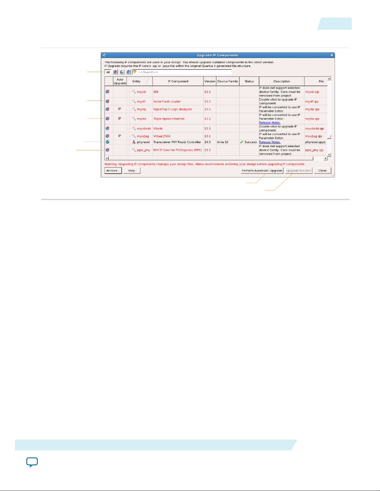
Displays upgrade
status for all IP cores
in the Project
Upgrades all IP core that support “Auto Upgrade”
Upgrades individual IP cores unsupported by “Auto Upgrade”
Checked IP cores
support “Auto Upgrade”
Successful
“Auto Upgrade”
Upgrade
unavailable
Double-click to
individually migrate
UG-01058
2014.12.19
Figure 1-7: Upgrading IP Cores
Upgrading IP Cores
1-11
Example 1-1: Upgrading IP Cores at the Command Line
You can upgrade IP cores that support auto upgrade at the command line. IP cores that do not
support automatic upgrade do not support command line upgrade.
• To upgrade a single IP core that supports auto-upgrade, type the following command:
quartus_sh –ip_upgrade –variation_files <my_ip_filepath/my_ip>.<hdl>
<qii_project>
Example:
quartus_sh -ip_upgrade -variation_files mega/pll25.v hps_testx
• To simultaneously upgrade multiple IP cores that support auto-upgrade, type the following
command:
quartus_sh –ip_upgrade –variation_files “<my_ip_filepath/my_ip1>.<hdl>;
<my_ip_filepath/my_ip2>.<hdl>” <qii_project>
Example:
quartus_sh -ip_upgrade -variation_files "mega/pll_tx2.v;mega/pll3.v"
hps_testx
IP cores older than Quartus II software version 12.0 do not support upgrade.
Note:
Altera verifies that the current version of the Quartus II software compiles the
previous version of each IP core. The Altera IP Release Notes reports any verifica‐
tion exceptions for Altera IP cores. Altera does not verify compilation for IP cores
older than the previous two releases.
About Floating-Point IP Cores
Send Feedback
Altera Corporation
Page 18

1-12
Migrating IP Cores to a Different Device
Related Information
Altera IP Release Notes
Migrating IP Cores to a Different Device
IP migration allows you to target the latest device families with IP originally generated for a different
device. Some Altera IP cores require individual migration to upgrade. The Upgrade IP Components
dialog box prompts you to double-click IP cores that require individual migration.
1. To display IP cores requiring migration, click Project > Upgrade IP Components. The Description
field prompts you to double-click IP cores that require individual migration.
2. Double-click the IP core name, and then click OK after reading the information panel.
The parameter editor appears showing the original IP core parameters.
3. For the Currently selected device family, turn off Match project/default, and then select the new
target device family.
4. Click Finish, and then click Finish again to migrate the IP variation using best-effort mapping to new
parameters and settings. Click OK if you are prompted that the IP core is unsupported for the current
device. A new parameter editor opens displaying best-effort mapped parameters.
5. Click Generate HDL, and then confirm the Synthesis and Simulation file options. Verilog is the
parameter editor default HDL for synthesis files. If your original IP core was generated for VHDL,
select VHDL to retain the original output HDL format.
6. To regenerate the new IP variation for the new target device, click Generate. When generation is
complete, click Close.
7. Click Finish to complete migration of the IP core. Click OK if you are prompted to overwrite IP core
files. The Device Family column displays the migrated device support. The migration process replaces
<my_ip>.qip with the <my_ip>.qsys top-level IP file in your project.
UG-01058
2014.12.19
Note:
If migration does not replace <my_ip>.qip with <my_ip>.qsys, click Project > Add/Remove
Files in Project to replace the file in your project.
8. Review the latest parameters in the parameter editor or generated HDL for correctness. IP migration
may change ports, parameters, or functionality of the IP core. During migration, the IP core's HDL
generates into a library that is different from the original output location of the IP core. Update any
assignments that reference outdated locations. If your upgraded IP core is represented by a symbol in a
supporting Block Design File schematic, replace the symbol with the newly generated <my_ip>.bsf
after migration.
Note:
The migration process may change the IP variation interface, parameters, and functionality.
This may require you to change your design or to re-parameterize your variant after the
Upgrade IP Components dialog box indicates that migration is complete. The Description
field identifies IP cores that require design or parameter changes.
Related Information
Altera IP Release Notes
Floating-Point IP Cores General Features
All Altera floating-point IP cores offer the following features:
Altera Corporation
About Floating-Point IP Cores
Send Feedback
Page 19

S E M
UG-01058
2014.12.19
IEEE-754 Standard for Floating-Point Arithmetic
• Support for floating-point formats.
• Input support for not-a-number (NaN), infinity, zero, and normal numbers.
• Optional asynchronous input ports including asynchronous clear (aclr) and clock enable (clk_en).
• Support for round-to-nearest-even rounding mode.
• Compute results of any mathematical operations according to the IEEE-754 standard compliance with
a maximum of 1 unit in the last place (u.l.p.) error. This assumption is applied to all floating-point IP
cores excluding complex matrix multiplication and inverse operations (for example,
ALTFP_MATRIX_MULTI and ALFP_MATRIX_INV), where a slight increase in errors is observed
due to the accumulation of errors during the mathematical operation.
Altera floating-point IP cores do not support denormal number inputs. If the input is a denormal value,
the IP core forces the value to zero and treats the value as a zero before going through any operation.
Related Information
FFT MegaCore Function User Guide
Altera also offers the single-precision floating-point option in the FFT MegaCore.
IEEE-754 Standard for Floating-Point Arithmetic
The floating-point IP cores implement the following representations in the IEEE-754 standard:
1-13
• Floating-point numbers
• Special values (zero, infinity, denormal numbers, and NaN bit combinations)
• Single-precision, double-precision, and single-extended precision formats for floating-point numbers
Floating-Point Formats
All floating-point formats have binary patterns. In Figure 1–1, S represents a sign bit, E represents an
exponent field, and M is the mantissa (part of a logarithm, or fraction) field.
For a normal floating-point number, a leading 1 is always implied, for example, binary 1.0011 or
decimal 1.1875 is stored as 0011 in the mantissa field. This format saves the mantissa field from using an
extra bit to represent the leading 1. However, the leading bit for a denormal number can be either 0 or 1.
For zero, infinity, and NaN, the mantissa field does not have an implied leading 1 nor any explicit leading
bit.
Figure 1-8: IEEE-754 Floating-Point Format
This figure shows a floating-point format.
Single-Precision Format
The single-precision format contains the following binary patterns:
• The MSB holds the sign bit.
• The next 8 bits hold the exponent bits.
• 23 LSBs hold the mantissa.
The total width of a floating-point number in the single-precision format is 32 bits. The bias for the
single-precision format is 127.
About Floating-Point IP Cores
Send Feedback
Altera Corporation
Page 20

S E M
31 30 23 22 0
S E M
63 62 52 51 0
1-14
Double-Precision Format
Figure 1-9: Single-Precision Representation
This figure shows a single-precision representation.
Double-Precision Format
The double-precision format contains the following binary patterns:
• The MSB holds the sign bit.
• The next 11 bits hold the exponent bits.
• 52 LSBs hold the mantissa.
The total width of a floating-point number in the double-precision format is 64 bits. The bias for the
double-precision format is 1023.
Figure 1-10: Double-Precision Representation
This figure shows a double-precision representation.
UG-01058
2014.12.19
Single-Extended Precision Format
The single-extended precision format contains the following binary patterns:
• The MSB holds the sign bit.
• The exponent and mantissa fields do not have fixed widths.
• The minimum exponent field width is 11 bits and must be less than the width of the mantissa field.
• The width of the mantissa field must be a minimum of 31 bits.
The sum of the widths of the sign bit, exponent field, and mantissa field must be a minimum of 43 bits
and a maximum of 64 bits. The bias for the single-extended precision format is unspecified in the
IEEE-754 standard. In these IP cores, a bias of 2(WIDTH_EXP–1)–1 is assumed for the single-extended
precision format.
Special Case Numbers
The following table lists the special case numbers defined by the IEEE-754 standard and the data bit
representations.
Table 1-4: Special Case Numbers in IEEE-754 Representation
Meaning Sign Field Exponent Field Mantissa Field
Zero Don’t care All 0’s All 0’s
Positive Denormalized 0 All 0’s Non-zero
Altera Corporation
About Floating-Point IP Cores
Send Feedback
Page 21

Sign
bit
Integer bits
31 0
UG-01058
2014.12.19
Rounding
Rounding
Meaning Sign Field Exponent Field Mantissa Field
Negative Denormalized 1 All 0’s Non-zero
Positive Infinity 0 All 1’s All 0’s
Negative Infinity 1 All 1’s All 0’s
Not-a-Number (NaN) Don’t care All 1’s Non-zero
The IEEE-754 standard defines four types of rounding modes, which are:
• round-to-nearest-even
• round-toward-zero
• round-toward-positive-infinity
• round-toward-negative-infinity
Altera floating-point IP cores support only the most commonly used rounding mode, which is the roundto-nearest-even mode (TO_NEAREST). With round-to-nearest-even, the IP core rounds the result to the
nearest floating-point number. If the result is exactly halfway between two floating-point numbers, the IP
core rounds the result so that the LSB becomes a zero, which is even.
1-15
Non-IEEE-754 Standard Format
Only the ALTFP_CONVERT and ALTERA_FP_FUNCTIONS (when the convert function is selected)
support the fixed point format.
The fixed-point data type is similar to the conventional integer data type, except that the fixed-point data
carries a predetermined number of fractional bits. If the width of the fraction is 0, the data becomes a
normal signed integer.
The notation for fixed-point format numbers in this user guide is Qm.f, where Q designates that the
number is in Q format notation, m is the number of bits used to indicate the integer portion of the
number, and f is the number of bits used to indicate the fractional portion of the number.
For example, Q4.12 describes a number with 4 integer bits and 12 fractional bits in a 16-bit word.
The following figures show the difference between the signed-integer format and the fixed-point format
for a 32-bit number.
Figure 1-11: Signed-Integer Format
About Floating-Point IP Cores
Send Feedback
Altera Corporation
Page 22

Sign
bit
Integer bits
31 0
Fraction bits
1-16
Floating-Points IP Cores Output Latency
Figure 1-12: Fixed-Point Format
Floating-Points IP Cores Output Latency
The IP cores measure the output latency in clock cycles and is different for each IP core. In some IP cores,
the precision modes determine the number of clock cycles between the input and output result. When you
select a mode, the options for latency are fixed for that mode.
For specific details about latency options, refer to the Output Latency section of your selected IP core in
this user guide.
Floating-Point IP Cores Design Example Files
The design examples for each IP core in this user guide use the IP Catalog and parameter editor to define
custom IP variations.
UG-01058
2014.12.19
Simulate the designs in the ModelSim®-Altera software to generate a waveform display of the device
behavior. You must be familiar with the ModelSim-Altera software before trying out the design examples.
Table 1-5: Design Files for Floating-Point IP Cores
Floating-Point IP Cores Design Files
ALTFP_ADD_SUB
ALTFP_DIV
ALTFP_MULT
ALTFP_SQRT
ALTFP_EXP
ALTFP_INV
• altfp_add_sub_DesignExample.zip (Quartus II design files)
• altfp_add_sub_ex_msim.zip (ModelSim-Altera files)
• altfp_div_DesignExample.zip (Quartus II design files)
• altfp_div_ex_msim.zip (ModelSim-Altera files)
• altfp_mult_DesignExample.zip (Quartus II design files)
• altfp_mult_ex_msim.zip (ModelSim-Altera files)
• altfp_sqrt_DesignExample.zip (Quartus II design files)
• altfp_sqrt_ex_msim.zip (ModelSim-Altera files)
• altfp_exp_DesignExample.zip (Quartus II design files)
• altfp_exp_ex_msim.zip (ModelSim-Altera files)
• altfp_inv_DesignExample.zip (Quartus II design files)
• altfp_inv_ex_msim.zip (ModelSim-Altera files)
Altera Corporation
About Floating-Point IP Cores
Send Feedback
Page 23

UG-01058
2014.12.19
Floating-Point IP Cores Design Example Files
Floating-Point IP Cores Design Files
1-17
ALTFP_INV_SQRT
• altfp_inv_sqrt_DesignExample.zip (Quartus II design files)
• altfp_inv_sqrt_ex_msim.zip (ModelSim-Altera files)
ALTFP_LOG
• altfp_log_DesignExample.zip (Quartus II design files)
• altfp_log_ex_msim.zip (ModelSim-Altera files)
ALTFP_ATAN Not Available
ALTFP_SINCOS Not Available
ALTFP_ABS
• altfp_mult_abs_DesignExample.zip (Quartus II design files)
• altfp_mult_abs_ex_msim.zip (ModelSim-Altera files)
ALTFP_COMPARE
• altfp_compare_DesignExample.zip (Quartus II design files)
• altfp_compare_ex_msim.zip (ModelSim-Altera files)
ALTFP_CONVERT
• altfp_convert_DesignExample.zip (Quartus II design files)
• altfp_convert_float2int_msim.zip (ModelSim-Altera files)
ALTERA_FP_ACC_CUSTOM Not Available
ALTERA_FP_FUNCTIONS Not Available
ALTERA_FP_MATRIX_INV
• altfp_matrix_inv_DesignExample.zip (Quartus II design files)
• altfp_matrix_inv_ex_msim.zip (ModelSim-Altera files)
ALTERA_FP_MATRIX_
Not Available
MULT
Related Information
• ALTERA_FP_MATRIX_INV Design Example: Matrix Inverse of Single-Precision Format
Numbers on page 2-6
• ALTFP_ADD_SUB Design Example: Addition of Double-Precision Format Numbers on page 53
• ALTFP_DIV Design Example: Division of Single-Precision on page 6-4
• ALTFP_MULT Design Example: Multiplication of Double-Precision Format Numbers on page 73
• ALTFP_SQRT Design Example: Square Root of Single-Precision Format Numbers on page 8-3
• ALTFP_EXP Design Example: Exponential of Single-Precision Format Numbers on page 9-2
• ALTFP_INV Design Example: Inverse of Single-Precision Format Numbers on page 10-2
This design example uses the ALTFP_INV IP core to compute the inverse of single-precision format
numbers. This example uses the parameter editor in the Quartus II software.
• ALTFP_INV_SQRT Design Example: Inverse Square Root of Single-Precision Format Numbers on
page 11-2
• ALTFP_LOG Design Example: Natural Logarithm of Single-Precision Format Numbers on page
12-2
• ALTFP_ABS Design Example: Absolute Value of Multiplication Results on page 15-2
About Floating-Point IP Cores
Send Feedback
Altera Corporation
Page 24

1-18
VHDL Component Declaration
• ALTFP_COMPARE Design Example: Comparison of Single-Precision Format Numbers on page
16-2
• ALTFP_CONVERT Design Example: Convert Double-Precision Floating-Point Format Numbers
on page 17-6
• Floating-Point IP Cores Design Examples
Provides the design example files for the Floating-Point IP cores
• ModelSim-Altera Software Support
Provides information about installation, usage, and troubleshooting
VHDL Component Declaration
The VHDL component declaration is located in the <Quartus II installation directory>\libraries\vhdl\altera_mf\
altera_mf_components.vhd
VHDL LIBRARY-USE Declaration
The VHDL LIBRARY-USE declaration is not required if you use the VHDL Component Declaration.
LIBRARY altera_mf;
UG-01058
2014.12.19
USE altera_mf_altera_mf_components.all;
Altera Corporation
About Floating-Point IP Cores
Send Feedback
Page 25

2014.12.19
www.altera.com
101 Innovation Drive, San Jose, CA 95134
ALTERA_FP_MATRIX_INV IP Core
2
UG-01058
Subscribe
Send Feedback
ALTERA_FP_MATRIX_INV Features
The ALTERA_FP_MATRIX_INV IP core offers the following features:
• Inversion of a matrix.
• Support for floating-point format in single precision.
• Support for VHDL and Verilog HDL languages.
• Support for matrix sizes up to are 4 × 4, 6 × 6, 8 × 8, 16 ×16, 32 × 32, and 64 × 64.
• Use of control signal, load.
• Use of handshaking signals: busy, outvalid, and done.
ALTERA_FP_MATRIX_INV Output Latency
The ALTERA_FP_MATRIX_INV IP core does not have a fixed output latency. Instead, it uses
handshaking signals to interface with external circuitry.
ALTERA_FP_MATRIX_INV Resource Utilization and Performance
This table lists the resource utilization and performance information for the ALTERA_FP_MATRIX_INV
IP core. The information was derived using the Quartus II software version 10.0
©
2014 Altera Corporation. All rights reserved. ALTERA, ARRIA, CYCLONE, ENPIRION, MAX, MEGACORE, NIOS, QUARTUS and STRATIX words and logos are
trademarks of Altera Corporation and registered in the U.S. Patent and Trademark Office and in other countries. All other words and logos identified as
trademarks or service marks are the property of their respective holders as described at www.altera.com/common/legal.html. Altera warrants performance
of its semiconductor products to current specifications in accordance with Altera's standard warranty, but reserves the right to make changes to any
products and services at any time without notice. Altera assumes no responsibility or liability arising out of the application or use of any information,
product, or service described herein except as expressly agreed to in writing by Altera. Altera customers are advised to obtain the latest version of device
specifications before relying on any published information and before placing orders for products or services.
ISO
9001:2008
Registered
Page 26

2-2
ALTERA_FP_MATRIX_INV Functional Description
UG-01058
2014.12.19
Table 2-1: ALTERA_FP_MATRIX_INV Resource Utilization and Performance for the Stratix IV Device Family
Precision
Single
Logic usage
Matrix
Size
Blocks
Adapti
ve
Logic
Modul
es
(ALMs)
DSP
Usage
(18 x
18
DSPs)
M9K M144K Memor
y (Bits)
Latenc
y
Throug
hput
(kb/s)
4× 4 2 21159 222 139 — 19919 PendingPendingPendin
Giga
Floatin
g-
Point
Operat
ions
per
Secon
d
(GFLO
PS)
f
MAX
(MHz)
221
g
6 × 6 2 59827 574 90 — 15759 PendingPendingPendin
170
g
8 × 8 2 5,538 63 49 — 53,736 2,501 3,987 15.26 332
16 ×
4 8,865 95 80 — 138,05111,057 855 30.93 329
16
32 ×
8 15,655 159 193 — 699,16452,625 165 55.12 290
32
64 ×
16 29,940 287 386 22 4,770,369281,50525 83.16 218
64
ALTERA_FP_MATRIX_INV Functional Description
A matrix inversion function is composed of the following components:
• Cholesky decomposition function.
The Cholesky decomposition function generates a lower triangular matrix.
• Triangular matrix inversion function.
The triangular matrix inversion process then generates the inverse of the lower triangular using
backward substitution.
• Matrix multiplication function.
The matrix multiplier multiplies the transpose of the inverse triangular matrix with the inverse
triangular matrix.
In linear algebra, the Cholesky decomposition states that every positive definite matrix A is decomposed
as A = L×LT
where, L is a lower triangular matrix, and LT denotes the transpose of L.
The property of invertible matrices states that (X×Y)-1 = X-1×Y-1 and the property of transpose states
that (XT )-1 = (X-1)T. Combining these two properties, the following equation represents a derivation of
a matrix inversion using the Cholesky decomposition method:
A-1 = (L×LT)-1
Altera Corporation
ALTERA_FP_MATRIX_INV IP Core
Send Feedback
Page 27

A
A L
L
-1
L
A(L )
Matrix A
Storage 1 Storage 2
Cholesky
Decomposition
Triangular Matrix
Inversion
Matrix
Multiplication
-f
X
=
T -1
L
-1
UG-01058
2014.12.19
= (LT)-1 × L-1
= (L-1)T × L-1
where a Cholesky decomposition function is needed to obtain L, a triangular matrix inversion is needed to
obtain L-1, and a matrix multiplication is needed for (L-1)T × L-1.
Figure 2-1: Matrix Inversion Flow Diagram
Cholesky Decomposition Function
The functions consists of two memory and two processing blocks. One of the memory blocks is the input
matrix memory block and is loaded with the input matrix in a row order, one element at a time. However,
during processing, this block is read in a column order, one element at a time when required.
Cholesky Decomposition Function
2-3
The other memory block is the processing matrix block which consists of multiple column memories to
enable an entire row to be read at once. During the loading of the input memory, the FPC datapath
preprocesses the input elements to generate the first column of the resulting triangular matrix. The top
element of the first column, l00, is the square root of the input matrix value a00. The rest of the first
column, li0 is the input value ai0 divided by l00. This preprocessing step introduces latency into the
load, during which the INIT_BUSY signal is asserted. The CALCULATE signal initiates and starts processing
after the INIT_BUSY signal is deasserted.
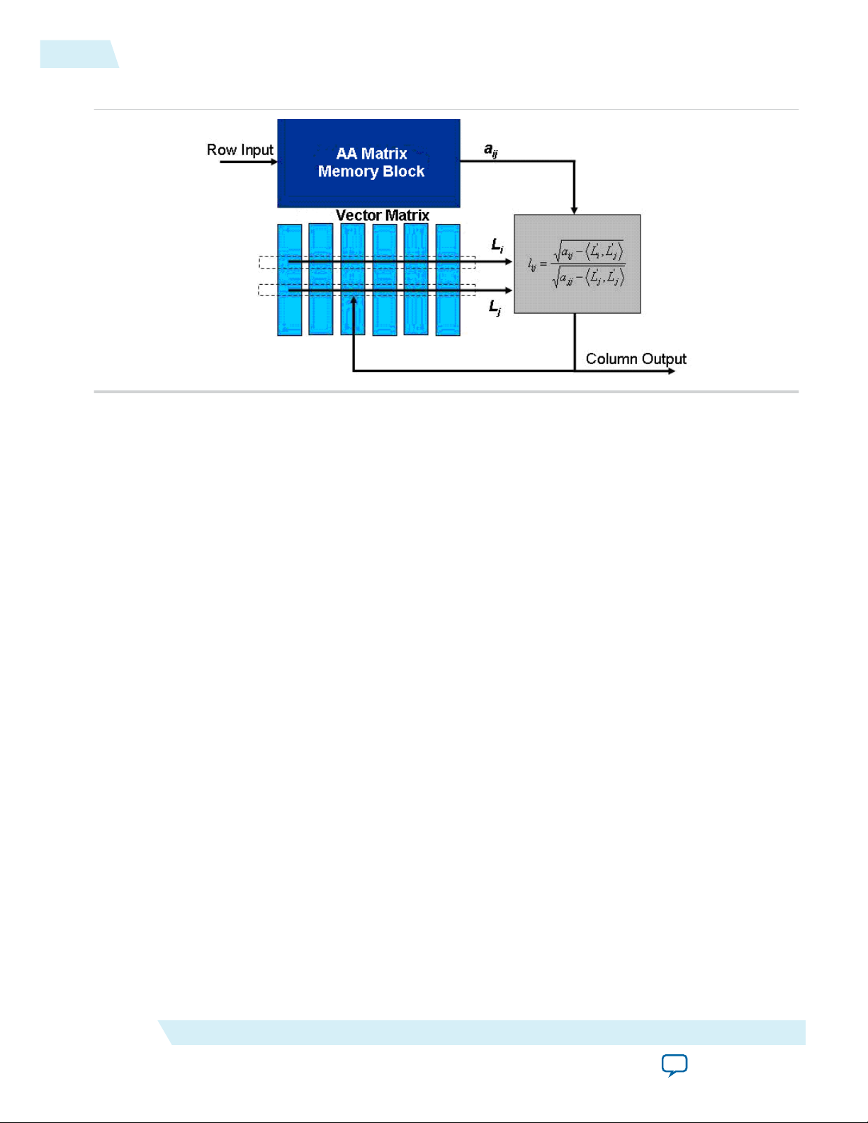
This figure shows the top-level architecture of the Cholesky decomposition function, where the
monolithic input memory and the column-wise processing memory, also known as the vector matrix, are
shown. The gray block is the FPC datapath section.
ALTERA_FP_MATRIX_INV IP Core
Send Feedback
Altera Corporation
Page 28
2-4
Cholesky Decomposition Function
Figure 2-2: Cholesky Decomposition Function Top-level Diagram
Although the Cholesky decomposition algorithm only operates on the lower triangular matrix, the core
requires the entire matrix to be loaded, during which the processing or vector memory is initialized.
UG-01058
2014.12.19
The FPC datapath is split into two sections. The first section, also known as the vector section, takes the
inner product of two vectors and subtracts it from the input matrix element, aij. The second section, also
known as the root section, calculates square roots and performs division by the square root. The first
element is loaded into both inputs of the root section and the outcome is its own square root. The first
element continues to stay latched in the left input field of the root section while all the other elements of
the first column are loaded into the right input field. The resulting output is the value of the respective
column element divided by the value of the first element of the Cholesky decomposition matrix.
During processing, two rows from the processing matrix are loaded. For the first element in each new
column, both rows have the same index; hence contain the same values. The first row is latched into the
input register of the vector section. For the rest of the column, the row index is increased, and a new a
ij
element and triangular matrix vector, Lj is loaded. The first result out of the vector section is latched onto
the left register of the root section. All results from the column, including the first result, are loaded into
the right register of the root section. The root section generates the square root of the first vector result,
while for the other results coming from the vector section, the number is divided by the square root of the
first result.
All calculated values are written to another memory block for further processing. The first column values
are output singly during preprocessing, while the values of other columns are burst out during processing.
There are only minor differences between the architectures for real and complex matrices. For the
complex matrix, both the input and processing memory blocks contain complex values. Similarly, all
values going into the vector section are complex numbers. The complex conjugate of the latched register
is obtained by simply inverting the sign bit. As for the root section, the structure is simplified by the
nature of the positive definite matrix. The diagonal value, which is the first value at the top of each
column in the decomposition, is always a real number so that the result from the inverse square root
calculation is always a real number. The complex multiplier in the root section is therefore a real scalar, so
only two real multipliers are required.
Altera Corporation
ALTERA_FP_MATRIX_INV IP Core
Send Feedback
Page 29

UG-01058
2014.12.19
Triangular Matrix Inversion
The triangular matrix, L, obtained from the Cholesky decomposition function is computed using the
triangular matrix inversion algorithm to get its inversion. The following MatLab pseudo code shows how
the inversion is carried out:
for j = n:-1:1,
X(j,j) = 1/L(j, j);
for k = j+1:n
for i = j+1:n
X(k, j) = X(k, j) + X(k, i)*L(i, j);
end;
end;
for k = j+1:n
X(k, j) = -X(j, j)*X(k, j);
end;
Triangular Matrix Inversion
2-5
The pseudo code is converted into an RTL file. The result, L-1 is stored in the input matrix storage in the
Cholesky decomposition function.
Matrix Multiplication
The final stage of the matrix inversion process involves multiplying the transpose of the inverse triangular
matrix with the inverse triangular matrix using the Altera Floating-Point Matrix Multiplier. The original
version of the matrix multiplier is modified for this purpose. As there are memory blocks already available
for the storage of the input matrices in the Cholesky decomposition function, the memory blocks in the
matrix multiplier are redundant and can be removed. Data is instead fed directly from the results stored at
the end stage of the triangular matrix inversion algorithm.
Matrix Inversion Operation
ALTERA_FP_MATRIX_INV IP Core
Send Feedback
Altera Corporation
Page 30

sysclk
enable
reset
load
datain
dataout
outvalid
busy
done
Loading Stage Processing Stage Output Stage
2-6
ALTERA_FP_MATRIX_INV Design Example: Matrix Inverse of Single-Precision Format Numbers
Figure 2-3: Matrix Inversion Timing Diagram
The following sequence describes the matrix inversion operation:
UG-01058
2014.12.19
1. The operation begins when the enable signal is asserted and the reset signal is deasserted.
2. The load signal is asserted to load data from the loaddata[] port for the input matrix. As long as the
load signal is high, data is loaded continuously for the input matrix.
3. The busy signal is asserted and the done signal is deasserted for a few clock cycles after the datain[]
signal is asserted.
4. The outvalid signal is asserted multiple times to signify the availability of valid data on the dataout[]
port. The number of times this signal is asserted equals the number of rows found in the output
matrix.
5. The busy and done signals are asserted when the last row of the output matrix has been burst out. This
assertion signifies the end of the matrix inversion operation on the first set of data.
ALTERA_FP_MATRIX_INV Design Example: Matrix Inverse of SinglePrecision Format Numbers
This design example uses the ALTERA_FP_MATRIX_INV IP core to show the matrix inversion
operation. The input matrix applied is an 8 × 8 matrix with a block size of 2. This example uses the
parameter editor GUI to define the core.
Related Information
• Floating-Point IP Cores Design Example Files on page 1-16
• Floating-Point IP Cores Design Examples
Provides the design example files for the Floating-Point IP cores
• ModelSim-Altera Software Support
Provides information about installation, usage, and troubleshooting
Altera Corporation
ALTERA_FP_MATRIX_INV IP Core
Send Feedback
Page 31
UG-01058
2014.12.19
ALTERA_FP_MATRIX_INV Design Example: Understanding the Simulation Results
ALTERA_FP_MATRIX_INV Design Example: Understanding the Simulation Results
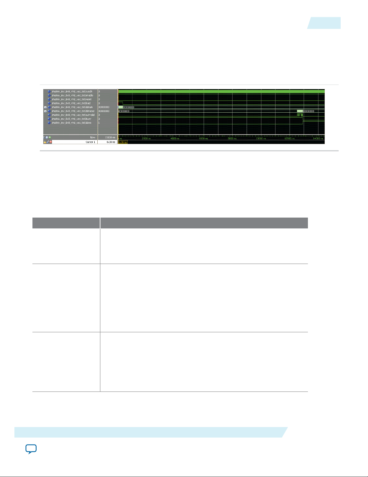
The simulation waveform in this design example is not shown in its entirety. Run the design example files
in the ModelSim-Altera software to see the complete simulation waveforms.
Figure 2-4: ALTERA_FP_MATRIX_INV ModelSim Simulation Waveform (Input Data)
This figure shows the expected simulation results in the ModelSim-Altera software.
This design example implements a floating-point matrix inversion to calculate the inverse value of
matrices in single-precision formats. The optional input ports (enable and reset) are enabled.
Table 2-2: Summary of Input Values and Corresponding Outputs
2-7
This table lists the inputs and corresponding outputs obtained from the simulation waveform. The number of
clock cycles obtained for each stage is based on the particular matrix size and parameter settings used in this
design example.
Time Event
0 ns – 10 ns Start sequence:
• The reset signal deasserts.
• The enable signal asserts.
19.86 ns – 340 ns Matrix input data load:
• The load signal asserts and remains high for 80 clock cycles.
• As long as the load signal is high, data for the input matrix is loaded
row by row.
• Input data is burst in regularly, one at every clock cycle.
• The load signal deasserts at 340 ns. The deassertion of the load signal
signifies the completion of the data load operation for the matrix.
27.5 ns Processing stage:
• The busy signal asserts while the done signal deasserts.
• The assertion of the busy signal and the deassertion of the done signal
indicate that the matrix inversion core is processing the input data.
• There are about 2500 clock cycles between the beginning of the
processing stage and the first available output value.
ALTERA_FP_MATRIX_INV IP Core
Send Feedback
Altera Corporation
Page 32

2-8
Sample Matrix Data
Time Event
UG-01058
2014.12.19
12527.5 –
12922.5 ns
Output stage:
• The outvalid signal asserts in intervals of 8 clock cycles. These series
• The output is an 8 x 8 matrix. Data is burst out regularly, row by row.
• At 12922.5 ns, the busy signal is asserted and the done signal is
• The assertion of the busy signal and the deassertion of the done signal
Sample Matrix Data
This section shows the random test data assigned to the input matrices and the results obtained from the
matrix inversion operation.
The following two sets of results are computed:
• PC-based results—these are results obtained from running the simulation in Matlab.
• FPGA-based results—these are results obtained from running the simulation in ModelSim.
This table lists the input and output data values presented in IEEE-754 Floating-point format.
of assertions signify the availability of valid data for the output matrix
on the outdata[] port.
deasserted.
indicate that the final output is written and a new matrix can be
processed.
Table 2-3: Input and Output Data
Matrix Data
Input
Matrix
40c89c6c 40b16187 40e21dfb 40847306 40c00d1d 40bbf0c4 40be4fc1 40953a30
40b16187 41244acb 410e61b9 40defe3a 40f8e982 40eff916 410e0ff4 41121d78
40e21dfb 410e61b9 41217d87 40d7f5f4 40fd78fa 410618c0 41060327 40ff4517
40847306 40defe3a 40d7f5f4 40b10427 40b6be88 40bbff4a 40d12685 40ca69f9
40c00d1d 40f8e982 40fd78fa 40b6be88 41146829 40ee188a 40fa2d80 40cf065c
40bbf0c4 40eff916 410618c0 40bbff4a 40ee188a 40ecbddf 40e3aa3a 40d60773
40be4fc1 410e0ff4 41060327 40d12685 40fa2d80 40e3aa3a 4111ed09 40ecd83c
40953a30 41121d78 40ff4517 40ca69f9 40cf065c 40d60773 40ecd83c 410847da
Altera Corporation
ALTERA_FP_MATRIX_INV IP Core
Send Feedback
Page 33

UG-01058
2014.12.19
Matrix Data
Sample Matrix Data
2-9
PC-based
Output
Matrix
FPGA-based
Output
Matrix
42148e03 42f5794f 421b33f4 430e0587 41ff0d66 c2f579a3 c2df1c28 c2f945bc
42f5794f 43d60be5 430944db 43f2dd63 42da2dd0 c3d1dd59 c3bff960 c3d98c47
421b33f4 430944db 424b067c 43204d17 421907da c3107054 c2fc035b c30d24b3
430e0587 43f2dd63 43204d17 440cc66b 43002bbb c3f4e779 c3dcd667 c3f7e3f3
41ff0d66 42da2dd0 421907da 43002bbb 41f5048b c2e44480 c2c91e6d c2df60c9
c2f579a3 c3d1dd59 c3107054 c3f4e779 c2e44480 43d89b61 43c003b9 43d685d3
c2df1c28 c3bff960 c2fc035b c3dcd667 c2c91e6d 43c003b9 43ae19b0 43c37f99
c2f945bc c3d98c47 c30d24b3 c3f7e3f3 c2df60c9 43d685d3 43c37f99 43ddb1bc
42148d06 42f5773e 421b32c4 430e0484 41ff0bb7 c2f577f4 c2df1a71 c2f943b1
42f5773e 43d609cf 430943a0 43f2db4a 42da2c09 c3d1db95 c3bff79e c3d98a34
421b32c4 430943a0 424b0515 43204be2 421906da c3106f53 c2fc014f c30d237c
430e0484 43f2db4a 43204be2 440cc563 43002adf c3f4e5c0 c3dcd4a7 c3f7e1df
41ff0bb7 42da2c09 421906da 43002adf 41f50322 c2e44314 c2c91cf5 c2df5f08
c2f577f4 c3d1db95 c3106f53 c3f4e5c0 c2e44314 43d899f3 43c00242 43d68414
c2df1a71 c3bff79e c2fc014f c3dcd4a7 c2c91cf5 43c00242 43ae1837 43c37dda
c2f943b1 c3d98a34 c30d237c c3f7e1df c2df5f08 43d68414 43c37dda 43ddafad
The difference between each result element of the PC-based and FPGA-based output matrices are as
shown:
Result differences (in decimal)
253 529 304 259 431 431 439 523
529 534 315 537 455 452 450 531
304 315 359 309 256 257 524 311
259 537 309 264 220 441 448 532
431 455 256 220 361 364 376 449
431 452 257 441 364 366 375 447
439 450 524 448 376 375 377 447
523 531 311 532 449 447 447 527
The difference between the two output matrices are due to the following reasons:
• Method of processing—Matlab uses sequential processing while Modelsim uses parallel processing.
• Method of conversion—Matlab first computes in double-precision format, and then only converts the
result into single-precision format. During this conversion, some units in the last place (ulp) are
expected to be lost.
ALTERA_FP_MATRIX_INV IP Core
Send Feedback
Altera Corporation
Page 34

datain
sysclk
reset
inst
ALTERA_FP_MATRIX_INV
dataout[]
busy
outvalid
done
load
enable
2-10
ALTERA_FP_MATRIX_INV Signals
ALTERA_FP_MATRIX_INV Signals
Figure 2-5: ALTERA_FP_MATRIX_INV Signals
UG-01058
2014.12.19
Table 2-4: ALTERA_FP_MATRIX_INV Input Signals
Port Name Required Description
sysclk Yes The clock input to the ALTERA_FP_MATRIX_INV IP core. This is
enable No Optional port. Allow calculation to take place when asserted. When
reset No Optional port. The core resets asynchronously when the reset signal
load Yes When asserted, loads the LOADDATA bus into the memory.
loaddata Yes Single-precision 32-bit matrix input value. Matrices load row by row.
Table 2-5: ALTERA_FP_MATRIX_INV Output Signals
Port Name Required Description
ready Yes When asserted, the core preprocesses the input data. The calculate
outdata Yes Single-precision 32-bit matrix result value. The matrix result value is
outvalid Yes When asserted, a valid output data is available. An entire row of the
the main system clock. All operations occur on the rising edge.
deasserted, no operation will take place and the outputs are
unchanged.
is asserted.
signal cannot be asserted until the ready signal is low.
written out row by row.
result matrix is written out as a burst. There is a gap between row
outputs, which will depend on the parameters.
Altera Corporation
ALTERA_FP_MATRIX_INV IP Core
Send Feedback
Page 35

UG-01058
2014.12.19
Port Name Required Description
done Yes When asserted, the last output has been written. A new matrix
multiply can be started with calculate. done will follow ready by
some fixed amount, depending on the parameters.
ALTERA_FP_MATRIX_INV Parameters
Table 2-6: ALTERA_FP_MATRIX_INV Parameters
Port Name Type Required Description
BLOCKS Integer No The number of memory blocks for the double-buffered
storage of matrix multiplication. The allowable range is
from 2 to 16.
DIMENSION Integer Yes The number of rows in the matrix. As the matrix is
square, this is also the number of columns in the matrix.
The supported dimensions are 4 x 4, 6 x 6, 8 x 8, 16 x 16,
32 x 32, and 64 x 64. The maximum supported input
dimension is 64 × 64.
ALTERA_FP_MATRIX_INV Parameters
2-11
This parameter also acts as the VECTORSIZE when
calling the ALTERA_FP_MATRIX_MULT IP core
internally.
WIDTH_EXP Integer Yes Specifies the precision of the exponent. The bias of the
exponent is always set to 2(WIDTH_EXP-1) -1 (that is,
127 for single-precision format). WIDTH_EXP must be 8 for
single-precision format and must be less than WIDTH_MAN.
The available value for WIDTH_EXP is 8.
WIDTH_MAN Integer Yes Specifies the precision of the mantissa. WIDTH_MAN must
be 23 when WIDTH_EXP is 8. Otherwise, WIDTH_MAN must
be a minimum of 31. WIDTH_MAN must be greater than
WIDTH_EXP. The sum of WIDTH_EXP and WIDTH_MAN must
be less than 64. Current available value for WIDTH_MAN is
only 23 for single precision.
ALTERA_FP_MATRIX_INV IP Core
Send Feedback
Altera Corporation
Page 36

2014.12.19
www.altera.com
101 Innovation Drive, San Jose, CA 95134
ALTERA_FP_MATRIX_MULT IP Core
3
UG-01058
Subscribe
Send Feedback
ALTERA_FP_MATRIX_MULT Features
The ALTERA_FP_MATRIX_MULT IP core offers the following features:
• Multiplication of two matrices.
• Support for floating-point formats in single and double precisions.
• Support for configurable performance and resource usage.
• Avalon streaming interfaces and full QSys compliance.
ALTERA_FP_MATRIX_MULT Output Latency
The ALTERA_FP_MATRIX_MULT IP core does not have a fixed output latency. Instead, the IP core
uses Avalon streaming interfaces and the c_valid signal on the output interface to indicate when output
data is available.
ALTERA_FP_MATRIX_MULT Resource Utilization and Performance
These tables list the resource utilization and performance information for the
ALTERA_FP_MATRIX_MULT IP core. The information was derived using the Quartus II software
version 14.1.
©
2014 Altera Corporation. All rights reserved. ALTERA, ARRIA, CYCLONE, ENPIRION, MAX, MEGACORE, NIOS, QUARTUS and STRATIX words and logos are
trademarks of Altera Corporation and registered in the U.S. Patent and Trademark Office and in other countries. All other words and logos identified as
trademarks or service marks are the property of their respective holders as described at www.altera.com/common/legal.html. Altera warrants performance
of its semiconductor products to current specifications in accordance with Altera's standard warranty, but reserves the right to make changes to any
products and services at any time without notice. Altera assumes no responsibility or liability arising out of the application or use of any information,
product, or service described herein except as expressly agreed to in writing by Altera. Altera customers are advised to obtain the latest version of device
specifications before relying on any published information and before placing orders for products or services.
ISO
9001:2008
Registered
Page 37

A.BC
=
3-2
ALTERA_FP_MATRIX_MULT Functional Description
UG-01058
2014.12.19
Table 3-1: ALTERA_FP_MATRIX_MULT Resource Utilization and Performance for the Arria 10 and Stratix V
Devices
Family Data
Format
Arri
a 10
(10A
Single
X06
6H2
F34I
Matrix A
Size
Matrix B
Size
Vector
Size
Memory
Blocks
ALMs M20ks DSP
8x8 8x8 8 2 979 12 8 409 131
16x16 16x16 8 2 1052 12 8 408 595
32x32 32x32 16 4 1579 25 16 373 2155
64x64 64x64 32 8 2677 49 32 379 8339
2LP)
Strat
ix V
(5SG
XEA
7K2
F40
Single
8x8 8x8 8 2 2637 14 8 404 125
16x16 16x16 8 2 2868 15 8 367 588
32x32 32x32 16 4 5427 27 16 356 2146
64x64 64x64 32 8 10311 51 32 348 8328
C2)
ALTERA_FP_MATRIX_MULT Functional Description
The matrix multiplier in the ALTERA_FP_MATRIX_MULT IP core multiplies matrix A and matrix B to
generate the output matrix C.
Blocks
FMax
(MHz)
Latency
(cycles)
(1)
The following figure shows the equation:
Figure 3-1: ALTERA_FP_MATRIX_MULT Equation
The matrix A and B can be loaded when the ready signal on their respective interfaces are asserted. When
the input matrices are loaded, the core will start computing the output. Valid signal on the output
interface will be asserted to indicate valid output data. The input data may be loaded at any time the ready
signal is asserted even when the previously loaded data is still being computed.
(1)
Latency is the time take to compute a dot product and does not include the time taken to load the input
matrices
Altera Corporation
ALTERA_FP_MATRIX_MULT IP Core
Send Feedback
Page 38

Row 0
. . . N-10 . . .
Row M-1
. . . N-10
Time
Matrix A
Memory
Matrix B
Memory
Registers Dot Product
Running Sums
+
UG-01058
2014.12.19
ALTERA_FP_MATRIX_MULT Functional Description
Figure 3-2: Matrix Serialization Format
An input matrix with M rows and N columns must be input as shown in this figure, where the Row 0 and
Column 0 element is first and Row M-1 and Column N-1 element is last. The result matrix will be output
in the same format.
The ALTERA_FP_MATRIX_MULT IP core consists of the following components:
• Memory blocks for the matrix A storage
• Memory blocks for the matrix B storage
• Dot product
• Accumulator
Figure 3-3: Top-Level View of the ALTERA_FP_MATRIX_MULT IP Core
This figure shows the top-level view of the ALTERA_FP_MATRIX_MULT IP core.
3-3
ALTERA_FP_MATRIX_MULT IP Core
Send Feedback
Altera Corporation
Page 39

clk
reset_n
a_ready
a_valid
a_data
inst
ALTERA_FP_MATRIX_MULT
c_valid
c_ready
c_data
b_ready
b_valid
b_data
3-4
ALTERA_FP_MATRIX_MULT Signals
The following lists the key features of the architecture:
• Matrix A and B storage are double buffered to allow processing to happen in parallel with data loading.
• Where the number of columns of A (A_COLUMNS) and rows of B (same as A_COLUMNS) are greater than
the size of the dot product (VECTOR_SIZE), the rows of A and columns of B are divided into sub rows
and sub columns respectively, each containing VECTOR_SIZE elements. In this case, A_COLUMNS/
VECTOR_SIZE iterations are needed to compute a full dot product corresponding to a single output
element.
• Matrix B memory has sufficient bandwidth so that all the data needed for the dot product can be
loaded at once.
• Matrix A memory is allocated with less bandwidth. The bandwidth of the matrix A is a parameter
(NUM_BLOCKS) that you can control. A sub row of matrix A is loaded into local registers over a number
of cycles before an iteration of the dot product. Once a sub row of Matrix A has been loaded into local
registers, all partial dot products involving that sub row are computed before another sub row is
loaded.
• For Arria 10 devices, where hardened single precision floating-point DSP blocks exist, those will be
used for single precision floating point arithmetic.
The matrix multiply architecture is not optimized for sparse matrices and constant matrices.
UG-01058
2014.12.19
ALTERA_FP_MATRIX_MULT Signals
Figure 3-4: ALTERA_FP_MATRIX_MULT Signals
This figure shows the signals for the ALTERA_FP_MATRIX_MULT IP core.
Table 3-2: ALTERA_FP_MATRIX_MULT Input Signals
These tables list the signals for the ALTERA_FP_MATRIX_MULT IP core.
Port Name Required Description
clk Yes The clock input port for the IP core.
Altera Corporation
ALTERA_FP_MATRIX_MULT IP Core
Send Feedback
Page 40

UG-01058
2014.12.19
Port Name Required Description
reset_n No Asynchronous active low reset port.
a_data Yes Matrix A input data.
a_valid Yes Matrix A Avalon streaming valid signal. When this signal is
asserted, data on a_data is valid.
b_data Yes Matrix B input data.
b_valid Yes Matrix B Avalon streaming valid signal. When this signal is asserted,
data on b_data is valid.
c_ready Yes Matrix C Avalon streaming ready signal. Ready latency is 0.
Table 3-3: ALTERA_FP_MATRIX_MULT Output Signals
Port Name Required Description
a_ready Yes Matrix A Avalon streaming ready signal. Ready latency is 0.
b_ready Yes Matrix B Avalon streaming ready signal. Ready latency is 0.
c_data Yes Matrix C input data.
ALTERA_FP_MATRIX_MULT Parameters
3-5
c_valid Yes Matrix C Avalon streaming valid signal. When this signal is asserted,
data on c_data is valid.
ALTERA_FP_MATRIX_MULT Parameters
This table lists the parameters for the ALTERA_FP_MATRIX_MULT IP core.
Table 3-4: ALTERA_FP_MATRIX_MULT IP Core Parameters
Parameter Value Description
Format Single (32 bit) or Double
(64 bit)
Rows in Matrix A 2-256 Number of rows in matrix A.
Columns in Matrix A 8-256 Integer multiples of
vector size. (Integer
multiples of Memory
Blocks.)
Rows in Matrix B 8-256 Number of rows in matrix B.
Columns of matrix B 2-256 Number of columns in matrix B.
The format of the input data.
Number of columns in matrix A. This
is also the number of rows in matrix
B.
ALTERA_FP_MATRIX_MULT IP Core
Send Feedback
Altera Corporation
Page 41

3-6
ALTERA_FP_MATRIX_MULT Parameters
Parameter Value Description
UG-01058
2014.12.19
Vector Size Allowed values are 8,16,
32, 64, 96, and 128.
Memory Blocks
The Vector Size must be
an integer multiple of
Memory Blocks. The
number of memory blocks
must be smaller than the
vector size.
The number of memory
blocks must be greater
than or equals to the ratio
of vector size divided by
the number of columns of
matrix B.
The size of the dot product which can
be computed in parallel. Where the
number of columns of matrix A and
rows of matrix B are greater than
Vector Size a number of iterations are
required to compute a full dot
product.
Vector Size also controls the matrix B
memory configuration. Increasing
the “Vector Size” increases the matrix
B memory bandwidth and the
number of memory blocks used.
Controls the memory configuration
of the matrix A storage. Increasing
this number increases the memory
bandwidth and the number of
memory blocks used.
Altera Corporation
ALTERA_FP_MATRIX_MULT IP Core
Send Feedback
Page 42

2014.12.19
www.altera.com
101 Innovation Drive, San Jose, CA 95134
ALTERA_FP_ACC_CUSTOM IP Core
4
UG-01058
Subscribe
Send Feedback
ALTERA_FP_ACC_CUSTOM Features
The ALTERA_FP_ACC_CUSTOM IP core offers the following features:
• Supports frequency driven cores.
• Supports VHDL RTL generation.
• Supports customization of the required range of the input and output values.
ALTERA_FP_ACC_CUSTOM Output Latency
The amount of latency is driven by the target frequency and the selected device family. You must set the
desired frequency and the target device before generating the IP core. The IP core reports the latency
when you set the parameters and when you generate the IP core. Then, use the reported latency to
incorporate the IP core into your design.
ALTERA_FP_ACC_CUSTOM Resource Utilization and Performance
©
2014 Altera Corporation. All rights reserved. ALTERA, ARRIA, CYCLONE, ENPIRION, MAX, MEGACORE, NIOS, QUARTUS and STRATIX words and logos are
trademarks of Altera Corporation and registered in the U.S. Patent and Trademark Office and in other countries. All other words and logos identified as
trademarks or service marks are the property of their respective holders as described at www.altera.com/common/legal.html. Altera warrants performance
of its semiconductor products to current specifications in accordance with Altera's standard warranty, but reserves the right to make changes to any
products and services at any time without notice. Altera assumes no responsibility or liability arising out of the application or use of any information,
product, or service described herein except as expressly agreed to in writing by Altera. Altera customers are advised to obtain the latest version of device
specifications before relying on any published information and before placing orders for products or services.
ISO
9001:2008
Registered
Page 43

4-2
ALTERA_FP_ACC_CUSTOM Resource Utilization and Performance
Table 4-1: ALTERA_FP_ACC_CUSTOM Resource Utilization and Performance
This table lists the resource utilization and performance information for the ALTERA_FP_ACC_CUSTOM IP
core. The information was derived using the Quartus II software version 13.1.
Device
Family
Input Data Accumulator
Size
Floati
Point
Form
ng
at
MaxM
SBX
MSBA LSBA PrimarySecon
Targe
t
Frequ
ency
(MHz)
Laten
cy
ALMs
DSP
Block
s
Logic
Registers
dary
M10K M20K f
UG-01058
2014.12.19
MAX
Arria
V
(5AG
XFB3
H4F4
0C5)
Cyclo
ne V
(5CG
XFC7
D6F3
1C7)
Stratix
V
(5SG
XEA7
K2F40
C2)
Arria
V
(5AG
XFB3
H4F4
0C5)
Double24 40 -52 270 15 866 0 1,166 106 0 -- 265
Double24 40 -52 230 15 830 0 1,102 32 0 -- 198
Double24 40 -52 400 15 968 0 1,655 27 -- 0 426
Single 12 20 -26 270 12 337 0 588 52 0 -- 309
Cyclo
ne V
(5CG
XFC7
D6F3
1C7)
Stratix
V
(5SG
XEA7
K2F40
C2)
Altera Corporation
Single 12 20 -26 230 12 383 0 494 28 0 -- 225
Single 12 20 -26 400 13 475 0 903 20 -- 0 450
ALTERA_FP_ACC_CUSTOM IP Core
Send Feedback
Page 44

clk
n
ALTERA_FP_ACC_CUSTOM
r
x
areset
en
xo
xu
ao
UG-01058
2014.12.19
Related Information
Fitter Resources Reports
Provides information about Quartus II resource utilization
ALTERA_FP_ACC_CUSTOM Signals
Figure 4-1: ALTERA_FP_ACC_CUSTOM
ALTERA_FP_ACC_CUSTOM Signals
4-3
Table 4-2: ALTERA_FP_ACC_CUSTOM Input Ports
Port Name Required Description
clk Yes All input signals, otherwise explicitly stated, must be synchronous to
areset Yes Asynchronous active-high reset. Deassert this signal synchronously to
en No Global enable signal. This port is optional.
x Yes Data input port.
n Yes Boolean port which signals the beginning of a new data set to be
Table 4-3: ALTERA_FP_ACC_CUSTOM Output Ports
Port Name Required Description
r Yes The running value of the accumulation.
this clock
the input clock to avoid metastability issues.
accumulated. This should go high together with the first element in the
new data set and should go low the next cycle. The data sets may be of
variable length and a new data set may be started at any time. The
accumulation result for an input will be available after the reported
latency.
ALTERA_FP_ACC_CUSTOM IP Core
Send Feedback
Altera Corporation
Page 45

4-4
ALTERA_FP_ACC_CUSTOM Parameters
Port Name Required Description
xo Yes The overflow flag for port x. The signal goes high when the exponent of
the input x is larger than maxMSBX. The signal remains high for the
entire data set. This flag invalidates port r. You should consider
increasing maxMSBX. This flag also indicate infinity and NaN.
xu Yes The underflow flag for port x. The signal goes high when the exponent
of the input x is smaller than LSBA. The signal remains high for the
entire data set. This flag does not invalidate port r. You should consider
lowering LSBA.
ao Yes The overflow flag for Accumulator. The signal goes high when the
exponent of the accumulated value is larger than MSBA. The signal
remains high for the entire data set. This flag invalidates port r. You
should consider increasing MSBA.
ALTERA_FP_ACC_CUSTOM Parameters
UG-01058
2014.12.19
Table 4-4: ALTERA_FP_ACC_CUSTOM Parameters
Category Parameter Values Description
Floating point
format
single,
double
Choose the floating point format of the input
data values. The output data values of the
accumulator is in the same format.
The default is single.
maxMSBX — The maximum weight of the MSB of an input.
For example, when adding probabilities in the 0
to 1 range set this weight to ceil(log2(1))=0. The
Input Data
xo output signal goes high when the MSB of an
input value has a weight larger than maxMSBX.
The result of the accumulation is then invalid. If
you are unsure about the range of the inputs,
then set the maxMSBX parameter to MSBA, at
the possible expense of increased resource
usage.
The default value is 12.
Altera Corporation
ALTERA_FP_ACC_CUSTOM IP Core
Send Feedback
Page 46

UG-01058
2014.12.19
ALTERA_FP_ACC_CUSTOM Parameters
Category Parameter Values Description
MSBA — The weight of the MSB of the accumulator. For
example, in a financial simulation, if the value of
a stock cannot exceed 100,000 dollars, use a
value of ceil(log2(100000))=17.
In a circuit simulation where the circuit adds
numbers in the 0 to 1 range, for one year, at 400
MHz, use a value of
ceil(log2(365 x 60 x 60 x 24 x 400 x 106))=54.
The ao output signal goes high when the MSB of
the accumulated value has a weight larger than
MSBA. The result of the accumulation is then
invalid. Altera recommends adding a few guard
bits to avoid possible accumulator overflow. A
few guard bits have little impact on the
accumulator size.
4-5
Accumulat
or Size
Required
Perform‐
ance
The default value is 20.
LSBA — The weight of the LSB of the accumulator and
the accuracy of the accumulator. Because an N
term accumulation can invalidate the log2(N)
LSBs of the accumulator, you must consider the
length of the accumulation and the range of the
inputs when setting this parameter.
For example, if a 2
-30
accuracy is required over
an accumulation of 1024 numbers, then set the
LSBA to:
(-30 - log2(1024)) = -40.
Any input 2e×1.F, where F is the mantissa and e
is less than the LSBA will be shifted out of the
accumulator. The au output signal goes high to
indicate this situation.
The default value is -26.
Target frequency Any positive
integer value.
Choose the frequency in MHz at which this core
is expected to run. This together with the target
device family will determine the amount of
pipelining in the core.
Optional Generate an enable
ALTERA_FP_ACC_CUSTOM IP Core
Send Feedback
port
The default value is 200 MHz.
— Choose if the accumulator should have an
enable signal.
This parameter is disabled by default.
Altera Corporation
Page 47

4-6
ALTERA_FP_ACC_CUSTOM Parameters
Category Parameter Values Description
Report — — Reports the latency of the device, which is the
number of cycles it takes for an accumulation to
propagate through the block from input to
output.
UG-01058
2014.12.19
Altera Corporation
ALTERA_FP_ACC_CUSTOM IP Core
Send Feedback
Page 48

2014.12.19
www.altera.com
101 Innovation Drive, San Jose, CA 95134
ALTFP_ADD_SUB IP Core
5
UG-01058
Subscribe
Send Feedback
ALTFP_ADD_SUB Features
The ALTFP_ADD_SUB IP core offers the following features:
• Dynamically configurable adder and subtracter functions.
• Optional exception handling output ports such as zero, overflow, underflow, and nan.
• Optimization of speed and area.
ALTFP_ADD_SUB Output Latency
The output latency options for the ALTFP_ADD_SUB IP core are the same for all three precision formats
—single, double, and single-extended. The options available are 7, 8, 9, 10, 11, 12, 13, and 14 clock cycles.
ALTFP_ADD_SUB Truth Table
Table 5-1: Truth Table for Addition/Subtraction Operations
DATAA[] DATAB[] SIGN BIT RESULT[] Overflow Underflow Zero NaN
Normal Normal 0 Zero 0 0 1 0
Normal Normal 0/1 Normal 0 0 0 0
Normal Normal 0/1 Denormal 0 1 1 0
Normal Normal 0/1 Infinity 1 0 0 0
Normal Denormal 0/1 Normal 0 0 0 0
Normal Zero 0/1 Normal 0 0 0 0
Normal Infinity 0/1 Infinity 1 0 0 0
©
2014 Altera Corporation. All rights reserved. ALTERA, ARRIA, CYCLONE, ENPIRION, MAX, MEGACORE, NIOS, QUARTUS and STRATIX words and logos are
trademarks of Altera Corporation and registered in the U.S. Patent and Trademark Office and in other countries. All other words and logos identified as
trademarks or service marks are the property of their respective holders as described at www.altera.com/common/legal.html. Altera warrants performance
of its semiconductor products to current specifications in accordance with Altera's standard warranty, but reserves the right to make changes to any
products and services at any time without notice. Altera assumes no responsibility or liability arising out of the application or use of any information,
product, or service described herein except as expressly agreed to in writing by Altera. Altera customers are advised to obtain the latest version of device
specifications before relying on any published information and before placing orders for products or services.
ISO
9001:2008
Registered
Page 49

5-2
ALTFP_ADD_SUB Resource Utilization and Performance
DATAA[] DATAB[] SIGN BIT RESULT[] Overflow Underflow Zero NaN
Normal NaN X NaN 0 0 0 1
Denormal Normal 0/1 Normal 0 0 0 0
Denormal Denormal 0/1 Normal 0 0 0 0
Denormal Zero 0/1 Zero 0 0 1 0
Denormal Infinity 0/1 Infinity 1 0 0 0
Denormal NaN X NaN 0 0 0 1
Zero Normal 0/1 Normal 0 0 0 0
Zero Denormal 0/1 Zero 0 0 1 0
Zero Zero 0/1 Zero 0 0 1 0
Zero Infinity 0/1 Infinity 1 0 0 0
Zero NaN X NaN 0 0 0 1
Infinity Normal 0/1 Infinity 1 0 0 0
Infinity Denormal 0/1 Infinity 1 0 0 0
UG-01058
2014.12.19
Infinity Zero 0/1 Infinity 1 0 0 0
Infinity Infinity 0/1 Infinity 1 0 0 0
Infinity NaN X NaN 0 0 0 1
NaN Normal X NaN 0 0 0 1
NaN Denormal X NaN 0 0 0 1
NaN Zero X NaN 0 0 0 1
NaN Infinity X NaN 0 0 0 1
NaN NaN X NaN 0 0 0 1
ALTFP_ADD_SUB Resource Utilization and Performance
The following lists the resource utilization and performance information for the ALTFP_ADD_SUB IP
core. The information was derived using the Quartus II software version 10.0.
Altera Corporation
ALTFP_ADD_SUB IP Core
Send Feedback
Page 50

UG-01058
2014.12.19
ALTFP_ADD_SUB Design Example: Addition of Double-Precision Format Numbers
Table 5-2: ALTFP_ADD_SUB Resource Utilization and Performance for the Stratix Series of Devices
5-3
Device Family Precision Optimiza‐
tion
Output
latency
Adaptive
Look-Up
Tables
(ALUTs)
Dedicated
Logic
Registers
(DLRs)
Adaptive
Logic
Modules
(ALMs)
f
MAX
(MHz)
7 594 376 385 228
speed
14 674 686 498 495
single
7 576 345 375 227
area
14 596 603 421 484
Stratix IV
7 1,198 687 824 187
speed
14 997 1,607 1,080 398
double
7 1,106 630 762 189
area
14 904 1,518 1,013 265
ALTFP_ADD_SUB Design Example: Addition of Double-Precision Format
Numbers
This design example uses the ALTFP_ADD_SUB IP core to perform the addition of double-precision
format numbers using the parameter editor in the Quartus II software.
Related Information
• Floating-Point IP Cores Design Example Files on page 1-16
• Floating-Point IP Cores Design Examples
Provides the design example files for the Floating-Point IP cores
• ModelSim-Altera Software Support
Provides information about installation, usage, and troubleshooting
ALTFP_ADD_SUM Design Example: Understanding the Simulation Results
The simulation waveform in this design example is not shown in its entirety. Run the design example files
in the ModelSim-Altera software to see the complete simulation waveforms.
Figure 5-1: ALTFP_ADD_SUB Simulation Waveform
ALTFP_ADD_SUB IP Core
Send Feedback
Altera Corporation
Page 51

5-4
ALTFP_ADD_SUB Signals
This design example implements a floating-point adder for the addition of double-precision format
numbers. All the optional input ports (clk_en and aclr) and optional output ports (overflow,
underflow, zero, and nan) are enabled.
In this example, the output latency of the multiplier is set to 7 clock cycles. Every addition result appears
at the result[] port 7 clock cycles after the input values are captured on the dataa[] and datab[] ports.
The following lists the inputs and corresponding outputs obtained from the simulation waveform.
Table 5-3: Summary of Input Values and Corresponding Outputs
Time Event
0 ns, start-up dataa[] value: 0000 0000 0000 0000h
datab[] value: 7FF0 0000 0000 0000h
Output value: All values seen on the output port before
the 7th clock cycle are merely due to the behavior of
the system during startup and should be disregarded.
4250 ns Output value: 7FF0 0000 0000 0000h
Exception handling ports: overflow asserts
The addition of zero at the input port dataa[], and
infinity value at the input port datab[] results in
infinity value.
UG-01058
2014.12.19
40,511 ns dataa[] value: 0000 0000 0000 0000h
datab[] value: 0000 0000 1000 0123h
The is the addition of a zero and a denormal value.
43,750 ns Output value: 0000 0000 0000 0000h
Exception handling ports: zero remains asserted.
Denormal inputs are not supported and are forced to
zero before addition takes place.This results in a zero.
ALTFP_ADD_SUB Signals
Altera Corporation
ALTFP_ADD_SUB IP Core
Send Feedback
Page 52

dataa[]
datab[]
add_sub
clock
clk_en
inst
ALTFP_ADD_SUB
result[]
overflow
nan
underflow
zero
aclr
UG-01058
2014.12.19
Figure 5-2: ALTFP_ADD_SUB
Table 5-4: ALTFP_ADD_SUB Input Ports
Port Name Required Description
ALTFP_ADD_SUB Signals
5-5
aclr No Asynchronous clear input for floating-point adder or subtractor. The
source is asynchronously reset when the aclr signal is asserted high.
add_sub No Optional input port to enable dynamic switching between the adder
and subtractor functions. The add_sub port must be used when the
DIRECTION parameter is set to VARIABLE. When the add_sub port is
high, result[] = dataa[] + datab[], otherwise, result[] =
dataa[] - datab[].
clk_en No Clock enable to the floating-point adder or subtractor. This port allows
addition or subtraction to occur when asserted high. When asserted
low, no operations occur and the outputs are unchanged.
clock Yes Clock input to the IP core.
dataa[] Yes Data input to the floating-point adder or subtractor. The MSB is the
sign bit, the next MSBs are the exponent, and the LSBs are the
mantissa bits. The size of this port is the total width of the sign bit, the
exponent bits, and the mantissa bits.
datab[] Yes Data input to the floating-point adder or subtractor. This port is
configured in the same way as dataa[].
Table 5-5: ALTFP_ADD_SUB Output Ports
Port Name Required Description
nan Yes NaN exception output. Asserted when an illegal addition or subtraction
occurs, such as infinity minus infinity. When an invalid addition or
subtraction occurs, a NaN value is output to the result[] port. Any
adding or subtracting involving NaN values also produces a NaN value.
ALTFP_ADD_SUB IP Core
Altera Corporation
Send Feedback
Page 53

5-6
ALTFP_ADD_SUB Parameters
Port Name Required Description
overflow Yes Overflow exception port. Asserted when the result of the addition or
subtraction, after rounding, exceeds or reaches infinity. Infinity is
defined as a number in which the exponent exceeds 2
result[] Yes Floating-point output result. Like the input values, the MSB is the sign,
WIDTH_EXP
the next MSBs are the exponent, and the LSBs are the mantissa. The size
of this port is the total width of the sign bit, exponent bits, and mantissa
bits.
underflow Yes Underflow port for the adder or subtractor. Asserted when the result of
the addition or subtraction, after rounding, the value is zero and the
inputs are not equal. The underflow port is also asserted when the
result is a denormalized number.
zero No Zero port for the adder or subtractor. Asserted when the result[] port
is zero.
ALTFP_ADD_SUB Parameters
UG-01058
2014.12.19
-1.
Table 5-6: ALTFP_ADD_SUB Parameters
Parameter Name Type Required Description
DIRECTION String Yes Specifies addition or subtraction operations. Values
are ADD, SUB, or VARIABLE. If this parameter is not
specified, the default is ADD. When the value is
VARIABLE, the add_sub port determines whether the
operation is addition or subtraction. The add_sub
port must be connected if the DIRECTION parameter
is set to VARIABLE. If the value is ADD or SUB, the add_
sub port is ignored.
PIPELINE Integer No Specifies the latency in clock cycles used in the
ALTFP_ADD_SUB IP core. The PIPELINE
parameter supports values of 7 through 14. If this
parameter is not specified, the default value is 11. In
general, a higher pipeline value produces better f
performance.
ROUNDING String Yes Specifies the rounding mode. The default value is
TO_NEAREST. Other rounding modes are currently
not supported.
OPTIMIZE String No Defines the design preference, whether the design is
optimized for speed (faster f
), or optimized for
MAX
area (lower resource count). Values are SPEED and
AREA. If this parameter is not specified, the default is
SPEED.
MAX
Altera Corporation
ALTFP_ADD_SUB IP Core
Send Feedback
Page 54

UG-01058
2014.12.19
ALTFP_ADD_SUB Parameters
Parameter Name Type Required Description
WIDTH_EXP Integer No Specifies the precision of the exponent. The bias of
the exponent is always set to 2 (WIDTH_EXP-1) -1
(that is, 127 for single-precision format and 1023 for
double-precision format). The WIDTH_EXP parameter
must be 8 for the single-precision mode and 11 for
the double-precision mode, or a minimum of 11 for
the single-extended precision mode. The WIDTH_EXP
parameter must be less than the WIDTH_MAN
parameter. The sum of WIDTH_EXP and the WIDTH_
MAN parameters must be less than 64. If this
parameter is not specified, the default is 8.
WIDTH_MAN Integer No Specifies the precision of the mantissa. The WIDTH_
MAN parameter must be 23 (to comply with the IEEE-
754 standard for the single-precision mode) when
the WIDTH_EXP parameter is 8. Otherwise, the WIDTH_
MAN parameter must have a value that is greater than
or equal to 31. The WIDTH_MAN parameter must be
greater than the WIDTH_EXP parameter. The sum of
the WIDTH_EXP and WIDTH_MAN parameters must be
less than 64. If this parameter is not specified, the
default is 23.
5-7
ALTFP_ADD_SUB IP Core
Send Feedback
Altera Corporation
Page 55

2014.12.19
www.altera.com
101 Innovation Drive, San Jose, CA 95134
ALTFP_DIV IP Core
6
UG-01058
Subscribe
Send Feedback
ALTFP_DIV Features
The ALTFP_DIV IP core offers the following features:
• Division functions.
• Optional exception handling output ports such as zero, division_by_zero, overflow, underflow,
and nan.
• Optimization of speed and area.
• Low latency option.
ALTFP_DIV Output Latency
The output latency options for the ALTFP_DIV IP core differs depending on the precision selected, the
width of the mantissa, or both. You have the choice of selecting the smaller figures of clock cycles delay in
your design if the low latency option is desired.
Table 6-1: Latency Options for Each Operation
Precision Mantissa Width Latency (in clock cycles)
Single 23 6, 14, 33
Double 52 10, 24, 61
©
2014 Altera Corporation. All rights reserved. ALTERA, ARRIA, CYCLONE, ENPIRION, MAX, MEGACORE, NIOS, QUARTUS and STRATIX words and logos are
trademarks of Altera Corporation and registered in the U.S. Patent and Trademark Office and in other countries. All other words and logos identified as
trademarks or service marks are the property of their respective holders as described at www.altera.com/common/legal.html. Altera warrants performance
of its semiconductor products to current specifications in accordance with Altera's standard warranty, but reserves the right to make changes to any
products and services at any time without notice. Altera assumes no responsibility or liability arising out of the application or use of any information,
product, or service described herein except as expressly agreed to in writing by Altera. Altera customers are advised to obtain the latest version of device
specifications before relying on any published information and before placing orders for products or services.
ISO
9001:2008
Registered
Page 56

6-2
ALTFP_DIV Truth Table
Precision Mantissa Width Latency (in clock cycles)
31 – 32 8, 18, 41
33 – 34 8, 18, 43
35 – 36 8, 18, 45
37 – 38 8, 18, 47
39 – 40 8, 18, 49
UG-01058
2014.12.19
Single Extended
41 10, 24, 41
42 10, 24, 51
43 – 44 10, 24, 53
45 – 46 10, 24, 55
47 – 48 10, 24, 57
49 – 50 10, 24, 59
51 – 52 10, 24, 61
ALTFP_DIV Truth Table
Table 6-2: Truth Table for Division Operations
DATAA[] DATAB[] SIGN BIT RESULT[] Overflow Underflo
w
Normal Normal 0/1 Normal 0 0 0 0 0
Normal Normal 0/1 Denorma
0 0 1 0 0
l
Zero Division-
by-zero
NaN
Normal Normal 0/1 Infinity 1 0 0 0 0
Normal Normal 0/1 Zero 0 1 1 0 0
Normal Denorma
Normal Zero 0/1 Infinity 0 0 0 1 0
Normal Infinity 0/1 Zero 0 0 1 0 0
Normal NaN X NaN 0 0 0 0 1
Denormal Normal 0/1 Zero 0 0 1 0 0
Denormal Denorma
Denormal Zero 0/1 NaN 0 0 0 0 1
Denormal Infinity 0/1 Zero 0 0 1 0 0
Altera Corporation
0/1 Infinity 0 0 0 1 0
l
0/1 NaN 0 0 0 0 1
l
ALTFP_DIV IP Core
Send Feedback
Page 57

UG-01058
2014.12.19
ALTFP_DIV Resource Utilization and Performance
6-3
DATAA[] DATAB[] SIGN BIT RESULT[] Overflow Underflo
w
Zero Division-
by-zero
NaN
Denormal NaN X NaN 0 0 0 0 1
Zero Normal 0/1 Zero 0 0 1 0 0
Zero Denorma
0/1 NaN 0 0 0 0 1
l
Zero Zero 0/1 NaN 0 0 0 0 1
Zero Infinity 0/1 Zero 0 0 1 0 0
Zero NaN X NaN 0 0 0 0 1
Infinity Normal 0/1 Infinity 0 0 0 0 0
Infinity Denorma
0/1 Infinity 0 0 0 0 0
l
Infinity Zero 0/1 Infinity 0 0 0 0 0
Infinity Infinity 0/1 NaN 0 0 0 0 1
Infinity NaN X NaN 0 0 0 0 1
NaN Normal X NaN 0 0 0 0 1
NaN Denorma
X NaN 0 0 0 1 1
l
NaN Zero X NaN 0 0 0 1 1
NaN Infinity X NaN 0 0 0 0 1
NaN NaN X NaN 0 0 0 0 1
ALTFP_DIV Resource Utilization and Performance
This table lists the resource utilization and performance information for the ALTFP_DIV IP core. The
information was derived using the Quartus II software version 10.0.
Table 6-3: ALTFP_DIV Resource Utilization and Performance for Stratix IV Devices
Logic Usage
Device family Precision
Single
Stratix IV
Double
Optimiza‐
tion
Output
latency
Adaptive
Look-Up
Tables
(ALUTs)
Speed 33 3,593 3,351 2,500 — 313
Area 33 1,646 2,074 1,441 — 308
Speed 61 13,867 13,143 10,196 — 292
Area 61 5,125 7,360 4,842 — 267
Dedicate
d Logic
Registers
(DLRs)
Adaptive
Logic
Modules
(ALMs)
18-bit
DSP
f
MAX
(MHz)
ALTFP_DIV IP Core
Send Feedback
Altera Corporation
Page 58

6-4
ALTFP_DIV Design Example: Division of Single-Precision
UG-01058
2014.12.19
Logic Usage
Device family Precision
Optimiza‐
tion
Output
latency
Adaptive
Look-Up
Tables
(ALUTs)
Dedicate
d Logic
Registers
(DLRs)
Adaptive
Logic
Modules
(ALMs)
Low Latency Option
— 6 207 304 212 16 154
Single
— 14 253 638 385 16 358
Stratix IV
— 10 714 1,077 779 44 151
Double
— 24 765 2,488 1,397 44 238
ALTFP_DIV Design Example: Division of Single-Precision
This design example uses the ALTFP_DIV IP core to implement a floating-point divider for the division
of single-precision format numbers with low latency. This example uses the parameter editor to define the
core.
Related Information
• Floating-Point IP Cores Design Example Files on page 1-16
• Floating-Point IP Cores Design Examples
Provides the design example files for the Floating-Point IP cores
• ModelSim-Altera Software Support
Provides information about installation, usage, and troubleshooting
18-bit
DSP
f
MAX
(MHz)
ALTFP_DIV Design Example: Understanding the Simulation Results
The simulation waveform in this design example is not shown in its entirety. Run the design example files
in the ModelSim-Altera software to see the complete simulation waveforms.
Figure 6-1: ALTFP_DIV Simulation Waveform
This figure shows the expected simulation results in the ModelSim-Altera software.
This design example implements a floating-point divider for the division of single-precision numbers
with a low latency option. The output latency is 6, hence every division generates the output result 6 clock
cycles later.
Altera Corporation
ALTFP_DIV IP Core
Send Feedback
Page 59

UG-01058
2014.12.19
ALTFP_DIV Design Example: Understanding the Simulation Results
Table 6-4: Summary of Input Values and Corresponding Outputs
This table lists the inputs and corresponding outputs obtained from the simulation in the waveform.
Time Event
0 ns, start-up dataa[] value: 0000 0000h
datab[] value: 0000 0000h
Output value: The undefined value is seen on the result[] port, which is ignored.
All values seen on the output port before the 6th clock cycle are merely due to the
behavior of the system during start-up and should be disregarded.
17600 ns Output value: 7FC0 0000h
Exception handling ports: nan asserts
The division of zeros result in a NaN.
2000 ns dataa[] value: 2D0B 496Ah
datab[] value: 3A5A FC26h
Both inputs hold normal values.
6-5
20800 ns Output result: 321F 6EC6h
Exception output ports: nan deasserts
The division of two normal value results in a normal value.
11000 ns dataa[] value: 046E 78BCh
datab[] value: 6798 698Bh
Both inputs hold normal values.
27200 ns Output value: 0h
Exception handling ports: underflow and zero asserts
The division of the two normal values results in a denormal value. As denormal
values are not supported, the result is zero and the underflow port asserts. The zero
port is also asserted to indicate that the result is zero.
2600 ns dataa[] value: 0D72 54A8h
datab[] value: 0070 0000h
The input port dataa[] holds a normal value while the input port datab[] holds a
denormal value.
36800 ns Output value: 7F80 0000h
ALTFP_DIV IP Core
Send Feedback
Exception handling ports: division_by_zero asserts
Denormal numbers are forced-zero values, therefore, attempts to divide a normal
value with a zero result in an infinity value.
Altera Corporation
Page 60

dataa[]
datab[]
clk_en
clock
inst
ALTFP_DIV
result[]
overflow
underflow
zero
nan
division_by_zero
aclr
6-6
ALTFP_DIV Signals
ALTFP_DIV Signals
Figure 6-2: ALTFP_DIV Signals
UG-01058
2014.12.19
Table 6-5: ALTFP_DIV Input Signals
Port Name Required Description
aclr No Asynchronous clear input for the floating-point divider. The source is
asynchronously reset when the aclr signal is asserted high.
clock Yes Clock input to the IP core.
clk_en No Clock enable to the floating-point divider. This port enables division.
This signal is active high. When this signal is low, no division takes
place and the outputs remain the same.
dataa[] Yes Numerator data input. The MSB is the sign bit, the next MSBs are the
exponent, and the LSBs are the mantissa. The size of this port is the
total width of the sign bit, exponent bits and mantissa bits.
datab[] Yes Denominator data input.The MSB is the sign bit, the next MSBs are
the exponent, and the LSBs are the mantissa. The size of this port is
the total width of the sign bit, exponent bits and mantissa bits.
Table 6-6: ALTFP_DIV Output Signals
Port Name Required Description
result[] Yes Divider output port. The division result (after rounding). As with the
input values, the MSB is the sign, the next MSBs are the exponent,
and the LSBs are the mantissa. The size of this port is the total width
of the sign bit, exponent bits, and mantissa bits.
Altera Corporation
ALTFP_DIV IP Core
Send Feedback
Page 61

UG-01058
2014.12.19
ALTFP_DIV Parameters
Port Name Required Description
overflow No Overflow port for the divider. Asserted when the result of the division
(after rounding) exceeds or reaches infinity. Infinity is defined as a
number in which the exponent exceeds 2WIDTH_EXP–1.
underflow No Underflow port for the divider. Asserted when the result of the
division (after rounding) is zero even though neither of the inputs to
the divider is zero, or when the result is a denormalized number.
zero No Zero port for the divider. Asserted when the value of result[] is
zero.
6-7
division_by_
zero
nan No NaN port. Asserted when an invalid division occurs, such as infinity
No Division-by-zero output port for the divider. Asserted when the value
of datab[] is a zero.
dividing infinity or zero dividing zero. A NaN value appears as
output at the result[] port. Any division of a NaN value causes the
nan output port to be asserted.
ALTFP_DIV Parameters
Table 6-7: ALTFP_DIV Parameters
Parameter Name Type Required Description
WIDTH_EXP Integer Yes Specifies the precision of the exponent. If this
parameter is not specified, the default is 8. The bias of
the exponent is always set to (2 ^ (WIDTH_EXP - 1)) - 1,
that is, 127 for single precision and 1023 for double
precision. The value of WIDTH_EXP must be 8 for single
precision, 11 for double precision, and a minimum of
11 for single extended precision.
The value of WIDTH_EXP must be less than the value of
WIDTH_MAN, and the sum of WIDTH_EXP and WIDTH_MAN
must be less than 64.
WIDTH_MAN Integer Yes Specifies the precision of the mantissa. If this
ROUNDING String Yes Specifies the rounding mode. The default value is TO_
ALTFP_DIV IP Core
Send Feedback
parameter is not specified, the default is 23. When
WIDTH_EXP is 8 and the floating-point format is the
single-precision format, the WIDTH_MAN value must be
23. Otherwise, the value of WIDTH_MAN must be a
minimum of 31.
The value of WIDTH_MAN must be greater than the value
of WIDTH_EXP, and the sum of WIDTH_EXP and WIDTH_
MAN must be less than 64.
NEAREST. The floating-point divider does not support
other rounding modes.
Altera Corporation
Page 62

6-8
ALTFP_DIV Parameters
Parameter Name Type Required Description
OPTIMIZE String No Specifies whether to optimize for area or for speed.
Values are AREA and SPEED. A value of AREA optimizes
the design using less total logic utilization or resources.
A value of SPEED optimizes the design for better
performance. If this parameter is not specified, the
default value is SPEED.
PIPELINE Integer No Specifies the number of clock cycles needed to produce
the result. For the single-precision format, the latency
options are 33, 14 or 6. For the double-precision
format, the latency options are 61, 24 or 10.
For the single-extended precision format, the value
ranges from a minimum of 41 to a maximum of 61.
For the low-latency option, the latency is determined
from the mantissa width. For a mantissa width of 31 to
40 bits, the value is 8 or 18. For a mantissa width of 41
bits or more, the value is 10 or 24.
UG-01058
2014.12.19
Altera Corporation
ALTFP_DIV IP Core
Send Feedback
Page 63

2014.12.19
www.altera.com
101 Innovation Drive, San Jose, CA 95134
ALTFP_MULT IP Core
7
UG-01058
Subscribe
Send Feedback
ALTFP_MULT IP Core Features
The ALTFP_MULT IP core offers the following features:
• Multiplication functions.
• Optional exception handling output ports such as zero, overflow, underflow, and nan.
• Optional dedicated multiplier circuitries in Cyclone and Stratix series.
ALTFP_MULT Output Latency
The output latency options for the ALTFP_MULT IP core are similar for all precisions.
Table 7-1: Latency Options for Each Precision Format
Precision Mantissa Width Latency (in clock cycles)
Single 23 5, 6, 10,11
Double 52 5, 6, 10,11
Single-Extended 31–52 5, 6, 10,11
ALTFP_MULT Truth Table
Table 7-2: Truth Table for Multiplier Operations
DATAA[] DATAB[] RESULT[] Overflow Underflow Zero NaN
Normal Normal Normal 0 0 0 0
Normal Normal Denormal 0 1 1 0
Normal Normal Infinity 1 0 0 0
©
2014 Altera Corporation. All rights reserved. ALTERA, ARRIA, CYCLONE, ENPIRION, MAX, MEGACORE, NIOS, QUARTUS and STRATIX words and logos are
trademarks of Altera Corporation and registered in the U.S. Patent and Trademark Office and in other countries. All other words and logos identified as
trademarks or service marks are the property of their respective holders as described at www.altera.com/common/legal.html. Altera warrants performance
of its semiconductor products to current specifications in accordance with Altera's standard warranty, but reserves the right to make changes to any
products and services at any time without notice. Altera assumes no responsibility or liability arising out of the application or use of any information,
product, or service described herein except as expressly agreed to in writing by Altera. Altera customers are advised to obtain the latest version of device
specifications before relying on any published information and before placing orders for products or services.
ISO
9001:2008
Registered
Page 64

7-2
ALTFP_MULT Resource Utilization and Performance
DATAA[] DATAB[] RESULT[] Overflow Underflow Zero NaN
Normal Normal Zero 0 1 1 0
Normal Denormal Zero 0 0 1 0
Normal Zero Zero 0 0 1 0
Normal Infinity Infinity 1 0 0 0
Normal NaN NaN 0 0 0 1
Denormal Normal Zero 0 0 1 0
Denormal Denormal Zero 0 0 1 0
Denormal Zero Zero 0 0 1 0
Denormal Infinity NaN 0 0 0 1
Denormal NaN NaN 0 0 0 1
Zero Normal Zero 0 0 1 0
Zero Denormal Zero 0 0 1 0
Zero Zero Zero 0 0 1 0
UG-01058
2014.12.19
Zero Infinity NaN 0 0 0 1
Zero NaN NaN 0 0 0 1
Infinity Normal Infinity 1 0 0 0
Infinity Denormal NaN 0 0 0 1
Infinity Zero NaN 0 0 0 1
Infinity Infinity Infinity 1 0 0 0
Infinity NaN NaN 0 0 0 1
NaN Normal NaN 0 0 0 1
NaN Denormal NaN 0 0 0 1
NaN Zero NaN 0 0 0 1
NaN Infinity NaN 0 0 0 1
NaN NaN NaN 0 0 0 1
ALTFP_MULT Resource Utilization and Performance
The following tables list the resource utilization and performance information for the ALTFP_MULT IP
core. The information was derived using the Quartus II software version 10.0.
Altera Corporation
ALTFP_MULT IP Core
Send Feedback
Page 65

UG-01058
2014.12.19
ALTFP_MULT Design Example: Multiplication of Double-Precision Format Numbers
Table 7-3: ALTFP_MULT Resource Utilization and Performance for Stratix IV Devices with Dedicated
Multiplier Circuitry
Logic usage
7-3
Device Family Precision
Output
latency
Adaptive
Look-Up
Tables
(ALUTs)
Dedicated
Logic
Registers
(DLRs)
Adaptive
Logic
Modules
(ALMs)
18-bit DSP
f
MAX
(MHz)
5 138 148 100 4 274
Single
11 185 301 190 4 445
Stratix IV
5 306 367 272 10 255
Double
11 419 523 348 10 395
ALTFP_MULT Design Example: Multiplication of Double-Precision Format
Numbers
This design example uses the ALTFP_MULT IP core to compute the multiplication results of two doubleprecision format numbers. This example uses the parameter editor GUI to define the core.
Related Information
• Floating-Point IP Cores Design Example Files on page 1-16
• Floating-Point IP Cores Design Examples
Provides the design example files for the Floating-Point IP cores
• ModelSim-Altera Software Support
Provides information about installation, usage, and troubleshooting
ALTFP_MULT Design Example: Understanding the Simulation Waveform
The simulation waveform in this design example is not shown in its entirety. Run the design example files
in the ModelSim-Altera software to see the complete simulation waveforms.
Figure 7-1: ALTFP_MULT Simulation Waveform
This figure shows the expected simulation results in the ModelSim-Altera software.
ALTFP_MULT IP Core
Send Feedback
Altera Corporation
Page 66

7-4
Parameters
This design example implements a floating-point multiplier for the multiplication of double-precision
format numbers. All the optional input ports (clk_en and aclr) and output ports (overflow, underflow,
zero, and nan) are enabled.
In this example, the latency is set to 6 clock cycles. Therefore, every multiplication result appears at the
result port 6 clock cycles later.
Table 7-4: Summary of Input Values and Corresponding Outputs
This table lists the inputs and corresponding outputs obtained from the simulation in the waveform.
Time Event
UG-01058
2014.12.19
0 ns, start-up dataa[] value: 0000 0000 0000 0000h
datab[] value: 4037 742C 3C9E ECC0h
Output value: All values seen on the output port before the 6th clock cycle are
merely due to the behavior of the system during start-up and should be disregarded.
110 ns Output value: 0000 0000 0000 0000h
Exception handling ports: zero asserts
The multiplication of zero at the input port dataa[], and a non-zero value at the
input port datab[] results in a zero.
600 ns dataa[] value: 7FF0 0000 0000 0000h
datab[] value: 4037 742C 3C9E ECC0h
This is the multiplication of an infinity value and a normal value.
710 ns Output value: 7FF0 0000 0000 0000h
Exception handling ports: overflow asserts
The multiplication of an infinity value and a normal value results in infinity. All
multiplications with an infinity value results in infinity except when infinity is
multiplied with a zero.
Parameters
Altera Corporation
ALTFP_MULT IP Core
Send Feedback
Page 67

UG-01058
2014.12.19
Table 7-5: ALTFP_MULT Megafunction Parameters
Parameter Name Type Required Description
WIDTH_EXP Integer No Specifies the value of the exponent. If this
ALTFP_MULT Signals
parameter is not specified, the default is 8.
The bias of the exponent is always 2
EXP - 1)
-1 (that is, 127 for the single-
(WIDTH_
precision format and 1023 for the doubleprecision format). WIDTH_EXP must be 8
for the single-precision format or a
minimum of 11 for the double-precision
format and the single-extended precision
format. WIDTH_EXP must less than WIDTH_
MAN. The sum of WIDTH_EXP and WIDTH_
MAN must be less than 64.
7-5
WIDTH_MAN
Integer No Specifies the value of the mantissa. If this
parameter is not specified, the default is
23. When WIDTH_EXP is 8 and the floating-
point format is single-precision, the
WIDTH_MAN value must be 23; otherwise,
the value of WIDTH_MAN must be a
minimum of 31. The WIDTH_MAN value
must always be greater than the WIDTH_
EXP value. The sum of WIDTH_EXP and
WIDTH_MAN must be less than 64.
DEDICATED_MULTIPLIER_ CIRCUITRY String No Specifies whether to use dedicated
multiplier circuitry. Values are AUTO, YES,
or NO. If this parameter is not specified, the
default is AUTO. If a device does not have
dedicated multiplier circuitry, the
DEDICATED_MULTIPLIER_CIRCUITRY
parameter has no effect and defaults to NO.
PIPELINE Integer No Specifies the number of clock cycles
needed to produce the multiplied result.
Values are 5, 6, 10, and 11. If this
parameter is not specified, the default is 5.
ALTFP_MULT Signals
Table 7-6: ALTFP_MULT IP Core Input Signals
Port Name Required Description
clock Yes Clock input to the IP core.
clk_en No Clock enable. Allows multiplication to take place when asserted high.
ALTFP_MULT IP Core
Send Feedback
When signal is asserted low, no multiplication occurs and the outputs
remain unchanged.
Altera Corporation
Page 68

7-6
ALTFP_MULT Signals
Port Name Required Description
aclr No Synchronous clear. Source is asynchronously reset when asserted
high.
dataa[] Yes Floating-point input data input to the multiplier. The MSB is the sign,
the next MSBs are the exponent, and the LSBs are the mantissa. This
input port size is the total width of sign bit, exponent bits, and
mantissa bits.
datab[] Yes Floating-point input data to the multiplier. The MSB is the sign, the
next MSBs are the exponent, and the LSBs are the mantissa. This
input port size is the total width of sign bit, exponent bits, and
mantissa bits.
Table 7-7: ALTFP_MULT IP Core Output Signals
Port Name Required Description
result[] Yes Output port for the multiplier. The floating-point result after
rounding. The MSB is the sign, the next MSBs are the exponent, and
the LSBs are the mantissa.
overflow No Overflow port for the multiplier. Asserted when the result of the
multiplication, after rounding, exceeds or reaches infinity. Infinity is
defined as a number in which the exponent exceeds 2
WIDTH_EXP
UG-01058
2014.12.19
-1.
underflow No Underflow port for the multiplier. Asserted when the result of the
multiplication (after rounding) is 0 while none of the inputs to the
multiplication is 0, or asserted when the result is a denormalized
number.
zero No Zero port for the multiplier. Asserted when the value of result[] is
0.
nan No NaN port for the multiplier. This port is asserted when an invalid
multiplication occurs, such as the multiplication of infinity and zero.
In this case, a NaN value is the output generated at the result[]
port. The multiplication of any value and NaN produces NaN.
Altera Corporation
ALTFP_MULT IP Core
Send Feedback
Page 69

2014.12.19
www.altera.com
101 Innovation Drive, San Jose, CA 95134
ALTFP_SQRT
8
UG-01058
Subscribe
Send Feedback
You can use the ports and parameters available to customize the ALTFP_SQRT IP core according to your
application.
ALTFP_SQRT Features
The ALTFP_SQRT IP core offers the following features:
• Square root functions.
• Optional exception handling output ports such as zero, overflow, and nan.
Output Latency
The output latency options for the ALTFP_SQRT megafunction differs depending on the precision
selected, the width of the mantissa, or both.
Table 8-1: Latency Options for Each Precision Format
Precision Mantissa Width Latency (in clock cycles)
Single 23 16, 28
Double 52 30, 57
©
2014 Altera Corporation. All rights reserved. ALTERA, ARRIA, CYCLONE, ENPIRION, MAX, MEGACORE, NIOS, QUARTUS and STRATIX words and logos are
trademarks of Altera Corporation and registered in the U.S. Patent and Trademark Office and in other countries. All other words and logos identified as
trademarks or service marks are the property of their respective holders as described at www.altera.com/common/legal.html. Altera warrants performance
of its semiconductor products to current specifications in accordance with Altera's standard warranty, but reserves the right to make changes to any
products and services at any time without notice. Altera assumes no responsibility or liability arising out of the application or use of any information,
product, or service described herein except as expressly agreed to in writing by Altera. Altera customers are advised to obtain the latest version of device
specifications before relying on any published information and before placing orders for products or services.
ISO
9001:2008
Registered
Page 70

8-2
ALTFP_SQRT Truth Table
Precision Mantissa Width Latency (in clock cycles)
UG-01058
2014.12.19
Single-extended
31
20, 36
32 20, 37
33 21, 38
34 21, 39
35 22, 40
36 22, 41
37 23, 42
38 23, 43
39 24, 44
40 24, 45
41 25, 46
42 25, 47
43 26, 48
44 26, 49
45 27, 50
46 27, 51
47 28, 52
48 28, 53
49 29, 54
50 29, 55
51 30, 56
ALTFP_SQRT Truth Table
Truth Table for Square Root Operations
DATA[] SIGN BIT RESULT[] NaN Overflow Zero
Normal 0 Normal 0 0 0
Denormal 0/1 Zero 0 0 1
Positive Infinity 0 Infinity 0 1 0
Negative Infinity 1 All 1’s 1 0 0
Positive NaN 0 All 1’s 1 0 0
Negative NaN 1 All 1’s 1 0 0
Normal 1 All 1’s 1 0 0
Altera Corporation
Zero 0/1 Zero 0 0 1
ALTFP_SQRT
Send Feedback
Page 71

UG-01058
2014.12.19
ALTFP_SQRT Resource Utilization and Performance
ALTFP_SQRT Resource Utilization and Performance
This table lists the resource utilization and performance information for the ALTFP_SQRT IP core. The
information was derived using the Quartus II software version 10.0.
Table 8-2: ALTFP_SQRT Resource Utilization and Performance for Stratix IV Devices
Logic usage
8-3
Device Family Precision
Output
latency
Adaptive
Look-Up
Tables
(ALUTs)
Dedicated
Login
Registers
(DLRs)
Adaptive
Logic
Modules
(ALMs)
f
MAX
(MHz)
Single 28 502 932 528 472
Stratix IV
Double 57 2,177 3,725 2,202 366
ALTFP_SQRT Design Example: Square Root of Single-Precision Format Numbers
This design example uses the ALTFP_SQRT IP core to compute the square root of single-precision format
numbers. This example uses the MegaWizard Plug-In Manager in the Quartus II software.
Related Information
• Floating-Point IP Cores Design Example Files on page 1-16
• Floating-Point IP Cores Design Examples
Provides the design example files for the Floating-Point IP cores
• ModelSim-Altera Software Support
Provides information about installation, usage, and troubleshooting
ALTFP_SQRT Design Example: Understanding the Simulation Results
The simulation waveform in this design example is not shown in its entirety. Run the design example files
in the ModelSim-Altera software to see the complete simulation waveforms.
These figures show the expected simulation results in the ModelSim-Altera software.
Figure 8-1: ALTFP_SQRT ModelSim Simulation Waveform (Input Data)
ALTFP_SQRT
Send Feedback
Altera Corporation
Page 72

8-4
ALTFP_SQRT Signals
Figure 8-2: ALTFP_SQRT ModelSim Simulation Waveform (Output Data)
This design example implements a floating-point square root function for single-precision format
numbers with all the exception output ports instantiated. The output ports include overflow, zero, and
nan.
The output latency is 28 clock cycles. Every square root computation generates the output result 28 clock
cycles later.
Table 8-3: Summary of Input Values and Corresponding Outputs
This table lists the inputs and corresponding outputs obtained from the simulation in the waveforms.
Time Event
UG-01058
2014.12.19
0 ns, start-up Output value: All values seen on the output port before the 28th clock cycle are merely
due to the behavior of the system during start-up and should be disregarded.
2 000 ns data[] value: 2D0B 496Ah
The data input is a normal number.
84 000 ns Output value: 363C D4EBh
The square root computation of a normal input results in a normal output.
14 000 ns data[] value: 0000 0000h
96 000 ns Output value: 0000 0000h
Exception handling ports: zero asserts
The square root computation of zero results in a zero.
23 000 ns data[] value: 7F80 0000h
The input is infinity.
105 000 ns Output value: 7F80 0000h
Exception handling ports: overflow asserts
ALTFP_SQRT Signals
Altera Corporation
ALTFP_SQRT
Send Feedback
Page 73

data[]
clock
clk_en
inst
ALTFP_SQRT
result[]
overflow
nan
zero
aclr
UG-01058
2014.12.19
Figure 8-3: ALTFP_SQRT Signals
Table 8-4: ALTFP_SQRT IP Core Input Signals
Port Name Required Description
ALTFP_SQRT Signals
8-5
clock Yes Clock input to the IP core.
clk_en No Clock enable that allows square root operations when the port is
asserted high. When the port is asserted low, no operation occurs and
the outputs remain unchanged.
aclr No Asynchronous clear. When the aclr port is asserted high, the function
is asynchronously reset.
Yes Floating-point input data. The MSB is the sign, the next MSBs are the
exponent, and the LSBs are the mantissa. This input port size is the
total width of sign bit, exponent bits, and mantissa bits.
Table 8-5: ALTFP_SQRT IP Core Output Signals
Port Name Required Description
result[] Yes Square root output port for the floating-point result. The MSB is the
sign, the next MSBs are the exponent, and the LSBs are the mantissa.
The size of this port is the total width of the sign bit, exponent bits,
and mantissa bits.
overflow Yes Overflow port. Asserted when the result of the square root (after
rounding) exceeds or reaches infinity. Infinity is defined as a number
in which the exponent exceeds 2
zero Yes Zero port. Asserted when the value of the result[] port is 0.
nan Yes NaN port. Asserted when an invalid square root occurs, such as
WIDTH_EXP
-1.
negative numbers or NaN inputs.
ALTFP_SQRT
Altera Corporation
Send Feedback
Page 74

8-6
ALTFP_SQRT Parameters
ALTFP_SQRT Parameters
Table 8-6: ALTFP_SQRT Parameters
Parameter Name Type Required Description
WIDTH_EXP Integer Yes Specifies the precision of the exponent. If this
parameter is not specified, the default is 8. The bias of
the exponent is always set to 2 (WIDTH_EXP -1) -1, that
is, 127 for the single-precision format and 1023 for the
double-precision format. The value of the WIDTH_EXP
parameter must be 8 for the single-precision format,
11 for the double-precision format, and a minimum of
11 for the single-extended precision format. The value
of the WIDTH_EXP parameter must be less than the
value of the WIDTH_MAN parameter, and the sum of the
WIDTH_EXP and WIDTH_MAN parameters must be less
than 64.
UG-01058
2014.12.19
WIDTH_MAN Integer Yes Specifies the value of the mantissa. If this parameter is
not specified, the default is 23. When the WIDTH_EXP
parameter is 8 and the floating-point format is singleprecision, the WIDTH_MAN parameter value must be 23.
Otherwise, the value of the WIDTH_MAN parameter must
be a minimum of 31. The value of the WIDTH_MAN
parameter must be greater than the value of the
WIDTH_EXP parameter. The sum of the WIDTH_EXP and
WIDTH_MAN parameters must be less than 64.
ROUNDING String Yes Specifies the rounding mode. The default value is TO_
NEAREST. Other rounding modes are not supported.
PIPELINE Integer Yes Specifies the number of clock cycles for the square
root results of the result[] port. Values are WIDTH_
MAN + 5 and ((WIDTH_MAN + 5/2)+2) as specified by
truncating the radix point.
Altera Corporation
ALTFP_SQRT
Send Feedback
Page 75

2014.12.19
www.altera.com
101 Innovation Drive, San Jose, CA 95134
ALTFP_EXP IP Core
9
UG-01058
Subscribe
Send Feedback
You can use the ports and parameters available to customize the ALTFP_EXP IP core according to your
application.
ALTFP_EXP Features
The ALTFP_EXP IP core offers the following features:
• Exponential value of a given input.
• Optional exception handling output ports such as zero, overflow, underflow, and nan.
Output Latency
The output latency options for the ALTFP_EXP megafunction differs depending on the precision
selected, the width of the mantissa, or both.
Precision Mantissa Width Latency (in clock cycles)
Single 23 17
Double 52 25
31 – 38 22
Single-extended
39 – 52 25
ALTFP_EXP Truth Table
Table 9-1: Truth Table for Exponential Operations
DATAA[] Calculation RESULT[] NaN Overflow Underflow Zero
Normal edata Normal 0 0 0 0
Normal edata Infinity 0 1 0 0
©
2014 Altera Corporation. All rights reserved. ALTERA, ARRIA, CYCLONE, ENPIRION, MAX, MEGACORE, NIOS, QUARTUS and STRATIX words and logos are
trademarks of Altera Corporation and registered in the U.S. Patent and Trademark Office and in other countries. All other words and logos identified as
trademarks or service marks are the property of their respective holders as described at www.altera.com/common/legal.html. Altera warrants performance
of its semiconductor products to current specifications in accordance with Altera's standard warranty, but reserves the right to make changes to any
products and services at any time without notice. Altera assumes no responsibility or liability arising out of the application or use of any information,
product, or service described herein except as expressly agreed to in writing by Altera. Altera customers are advised to obtain the latest version of device
specifications before relying on any published information and before placing orders for products or services.
ISO
9001:2008
Registered
Page 76

9-2
ALTFP_EXP Resource Utilization and Performance
DATAA[] Calculation RESULT[] NaN Overflow Underflow Zero
UG-01058
2014.12.19
Normal (numbers
edata 1 0 0 1 0
of small magnitude)
Normal (negative
edata 0 0 0 1 0
numbers of large
magnitude)
Denormal e0 1 0 0 0 0
Zero e0 1 0 0 0 0
Infinity (+) e+ Infinity 0 0 0 0
Infinity (-) e- 0 0 0 0 1
NaN — NaN 1 0 0 0
ALTFP_EXP Resource Utilization and Performance
This table lists the resource utilization and performance information for the ALTFP_EXP IP core. The
information was derived using the Quartus II software version 10.0.
Table 9-2: ALTFP_EXP Resource Utilization and Performance for Stratix IV Devices
Logic usage
Device Family Precision
Output
Latency
Adaptive
Look-Up
Tables
(ALUTs)
Dedicated
Logic
Registers
(DLRs)
Adaptive
Logic
Modules
(ALMs)
18-bit DSP
f
MAX
(MHz)
Single 17 631 521 448 19 284
Stratix IV
Double 25 4,104 2,007 2,939 46 279
ALTFP_EXP Design Example: Exponential of Single-Precision Format Numbers
This design example uses the ALTFP_EXP IP core to compute the exponential value of single-precision
format numbers. This example uses the MegaWizard Plug-In Manager in the Quartus II software.
Related Information
• Floating-Point IP Cores Design Example Files on page 1-16
• Floating-Point IP Cores Design Examples
Provides the design example files for the Floating-Point IP cores
• ModelSim-Altera Software Support
Provides information about installation, usage, and troubleshooting
(2)
Any denormal input is treated as a zero before going through the exponential process.
Altera Corporation
ALTFP_EXP IP Core
Send Feedback
Page 77
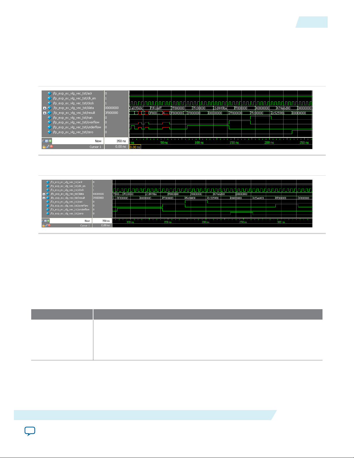
UG-01058
2014.12.19
ALTFP_EXP Design Example: Understanding the Simulation Results
ALTFP_EXP Design Example: Understanding the Simulation Results
The simulation waveform in this design example is not shown in its entirety. Run the design example files
in the ModelSim-Altera software to see the complete simulation waveforms.
These figures show the expected simulation results in the ModelSim-Altera software.
Figure 9-1: ALTFP_EXP ModelSim Simulation Waveform (Input Data)
Figure 9-2: ALTFP_EXP ModelSim Simulation Waveform (Output Data)
9-3
This design example implements a floating-point exponential for the single-precision format numbers.
The optional input ports (clk_en and aclr) and all four exception handling output ports (nan, overflow,
underflow, and zero) are enabled.
For single-precision format numbers, the latency is fixed at 17 clock cycles. Therefore, every exponential
operation outputs the results 17 clock cycles later.
Table 9-3: Summary of Input Values and Corresponding Outputs
This table lists the inputs and corresponding outputs obtained from the simulation in the waveforms.
Time Event
0 ns, start-up data[] value: 1A03 568Ch
Output value: An undefined value is seen on the result[] port, which is ignored. All
values seen on the output port before the 17th clock cycle are merely due to the
behavior of the system during start-up and should be disregarded.
ALTFP_EXP IP Core
Send Feedback
Altera Corporation
Page 78

9-4
ALTFP_EXP Signals
Time Event
82.5 ns Output value: 3F80 0000h
As the input value of 1A03568Ch is a very small number, it is seen as a value that is
approaching zero, and the result approaches 1 (which is represented by 3F800000).
Exponential operations carried out on numbers of very small magnitudes result in a
1 and assert the underflow flag.
Exception handling ports: underflow asserts
30 ns data[] value: F3FC DEFFh
This is a normal negative value of a very large magnitude.
112.5 ns Output value: 0000 0000h
The outcome of exponential operations on negative numbers of very large
magnitudes approaches zero.
Exception handling ports: underflow remains asserted
60 ns data[] value: 7F80 0000h
UG-01058
2014.12.19
This is a positive infinite value.
142.5 ns Output value: 7F80 0000h
The operation on positive infinite values results in infinity.
Exception handling ports: underflow deasserts, overflow asserts
90 ns data[] value: 7FC0 0000h
This is a NaN.
172.5 ns Output value: 7FC0 0000h
The exponential of a NaN results in a NaN.
Exception handling ports: nan asserts
120 ns data[] value: C1D4 49BAh
This is a normal value.
202.5 ns Output value: 2C52 5981h
The result is a normal value.
Exception handling ports: nan deasserts
ALTFP_EXP Signals
Altera Corporation
ALTFP_EXP IP Core
Send Feedback
Page 79
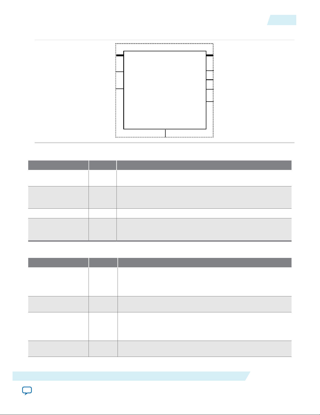
data[]
clk_en
clock
inst
ALTFP_EXP
result[]
underflow
zero
nan
underflow
aclr
UG-01058
2014.12.19
Figure 9-3: ALTFP_EXP Signals
Table 9-4: ALTFP_EXP IP Core Input Signals
Port Name Required Description
ALTFP_EXP Signals
9-5
aclr No Asynchronous clear. When the aclr port is asserted high the function
is asynchronously reset.
clk_en No Clock enable. When the clk_en port is asserted high, an exponential
value operation takes place. When this signal is asserted low, no
operation occurs and the outputs remain unchanged.
clock Yes Clock input to the IP core.
data[] Yes Floating-point input data. The MSB is the sign, the next MSBs are the
exponent, and the LSBs are the mantissa. This input port size is the
total width of the sign bit, exponent bits, and mantissa bits.
Table 9-5: ALTFP_EXP IP Core Output Signals
Port Name Required Description
result[] Yes The floating-point exponential result of the value at data[]. The MSB
is the sign, the next MSBs are the exponent, and the LSBs are the
mantissa. The size of this port is the total width of the sign bit,
exponent bits, and mantissa bits.
overflow No Overflow exception output. Asserted when the result of the operation
(after rounding) is infinite.
underflow No Underflow exception output. Asserted when the result of the exponen‐
tial approaches 1 (from numbers of very small magnitude), or when
the result approaches 0 (from negative numbers of very large
magnitudes).
ALTFP_EXP IP Core
zero No Zero exception output. Asserted when the value in the result[] port
is zero.
Send Feedback
Altera Corporation
Page 80

9-6
ALTFP_EXP Parameters
Port Name Required Description
nan No NaN exception output. Asserted when an invalid operation occurs.
Any operation involving NaN also asserts the nan port.
ALTFP_EXP Parameters
Table 9-6: ALTFP_EXP IP Core Parameters
Parameter Name Type Required Description
WIDTH_EXP Integer Yes Specifies the precision of the exponent. If this
parameter is not specified, the default is 8. The bias
of the exponent is always set to 2
that is, 127 for the single-precision format and 1023
for the double-precision format. The value of the
WIDTH_EXP parameter must be 8 for the single-
precision format, 11 for the double-precision
format, and a minimum of 11 for the singleextended precision format. The value of the WIDTH_
EXP parameter must be less than the value of the
WIDTH_MAN parameter, and the sum of the WIDTH_
EXP and WIDTH_MAN parameters must be less than
64.
(WIDTH_EXP -1)
UG-01058
2014.12.19
-1,
WIDTH_MAN
Integer Yes Specifies the value of the mantissa. If this parameter
is not specified, the default is 23. When the WIDTH_
EXP parameter is 8 and the floating-point format is
single-precision, the WIDTH_MAN parameter value
must be 23. Otherwise, the value of the WIDTH_MAN
parameter must be a minimum of 31. The value of
the WIDTH_MAN parameter must be greater than the
value of the WIDTH_EXP parameter. The sum of the
WIDTH_EXP and WIDTH_MAN parameters must be less
than 64.
PIPELINE Integer Yes Specifies the amount of latency, expressed in clock
cycles, used in the ALTFP_EXP IP core. Acceptable
pipeline values are 17, 22, and 25 cycles of latency.
Create the ALTFP_EXP IP core with the
MegaWizard Plug-In Manager to calculate the value
for this parameter.
ROUNDING String Yes Specifies the rounding mode. The default value is
TO_NEAREST. Other rounding modes are not
supported.
Altera Corporation
ALTFP_EXP IP Core
Send Feedback
Page 81

2014.12.19
www.altera.com
101 Innovation Drive, San Jose, CA 95134
ALTFP_INV IP Core
10
UG-01058
Subscribe
You can use the ports and parameters available to customize the ALTFP_INV IP core according to your
application.
ALTFP_INV Features
The ALTFP_INV IP core offers the following features:
• Inverse value of a given input.
• Optional exception handling output ports such as zero, division_by_zero, underflow, and nan.
Output Latency
The output latency options for the ALTFP_INV megafunction differs depending on the precision
selected, the width of the mantissa, or both.
Precision Mantissa Width Latency (in clock cycles)
Send Feedback
Single 23 20
Double 52 27
31 – 39 20
Single Extended
40 – 52 27
ALTFP_INV Truth Table
Table 10-1: Truth Table for Inverse Operations
DATA[] SIGN BIT RESULT[] Underflow Zero Division_by_
zero
Normal 0/1 Normal 0 0 0 0
©
2014 Altera Corporation. All rights reserved. ALTERA, ARRIA, CYCLONE, ENPIRION, MAX, MEGACORE, NIOS, QUARTUS and STRATIX words and logos are
trademarks of Altera Corporation and registered in the U.S. Patent and Trademark Office and in other countries. All other words and logos identified as
trademarks or service marks are the property of their respective holders as described at www.altera.com/common/legal.html. Altera warrants performance
of its semiconductor products to current specifications in accordance with Altera's standard warranty, but reserves the right to make changes to any
products and services at any time without notice. Altera assumes no responsibility or liability arising out of the application or use of any information,
product, or service described herein except as expressly agreed to in writing by Altera. Altera customers are advised to obtain the latest version of device
specifications before relying on any published information and before placing orders for products or services.
NaN
ISO
9001:2008
Registered
Page 82

10-2
ALTFP_INV Resource Utilization and Performance
UG-01058
2014.12.19
DATA[] SIGN BIT RESULT[] Underflow Zero Division_by_
zero
Normal 0/1 Denormal 1 1 0 0
Normal 0/1 Infinity 0 0 0 0
Normal 0/1 Zero 1 1 0 0
Denormal 0/1 Infinity 0 0 1 0
Zero 0/1 Infinity 0 0 1 0
Infinity 0/1 Zero 0 1 0 0
NaN X NaN 0 0 0 1
ALTFP_INV Resource Utilization and Performance
This table lists the resource utilization and performance information for the ALTFP_INV IP core. The
information was derived using the Quartus II software version 10.0.
Table 10-2: ALTFP_INV Resource Utilization and Performance for Stratix IV Devices
Logic usage
NaN
Device Family Precision
Output
Latency
Adaptive
Look-Up
Tables
(ALUTs)
Dedicated
Logic
Registers
(DLRs)
Adaptive
Logic
Modules
(ALMs)
18-Bit DSP
f
MAX
(MHz)
Single 20 401 616 373 16 412
Stratix IV
Double 27 939 1,386 912 48 203
ALTFP_INV Design Example: Inverse of Single-Precision Format Numbers
This design example uses the ALTFP_INV IP core to compute the inverse of single-precision format
numbers. This example uses the parameter editor in the Quartus II software.
Related Information
• Floating-Point IP Cores Design Example Files on page 1-16
• Floating-Point IP Cores Design Examples
Provides the design example files for the Floating-Point IP cores
• ModelSim-Altera Software Support
Provides information about installation, usage, and troubleshooting
(3)
Any calculated or computed denormal output is replaced by a zero and asserts the zero and underflow flags.
(4)
Any denormal input is treated as a zero before going through the inverse process.
Altera Corporation
ALTFP_INV IP Core
Send Feedback
Page 83
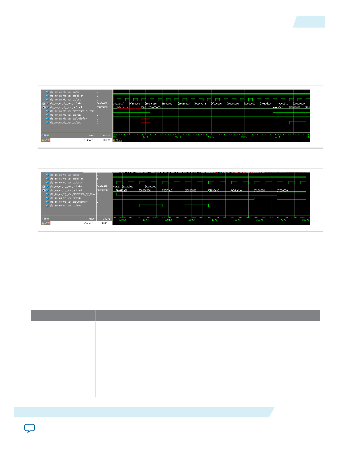
UG-01058
2014.12.19
ALTFP_INV Design Example: Understanding the Simulation Results
ALTFP_INV Design Example: Understanding the Simulation Results
The simulation waveform in this design example is not shown in its entirety. Run the design example files
in the ModelSim-Altera software to see the complete simulation waveforms.
These figures show the expected simulation results in the ModelSim-Altera software.
Figure 10-1: ALTFP_INV ModelSim Simulation Waveform (Input Data)
Figure 10-2: ALTFP_INV ModelSim Simulation Waveform (Output Data)
10-3
This design example implements a floating-point inverse for single-precision format numbers. The
optional input ports (clk_en and aclr) and all four exception handling output ports (division_by_zero,
nan, zero, and underflow) are enabled.
The latency is fixed at 20 clock cycles; therefore, every inverse operation outputs results 20 clock cycles
later.
This table lists the inputs and corresponding outputs obtained from the simulation in the waveforms.
Table 10-3: Summary of Input Values and Corresponding Outputs
Time Event
0 ns, start-up data[] value: 34A2 E42Fh
Output value: An undefined value is seen on the result[] port, which is ignored.
All values seen on the output port before the 20th clock cycle are merely due to the
behavior of the system during start-up and should be disregarded.
97.5 ns Output value: 4A49 2A2Fh
Exception handling ports: division_by_zero deasserts
The inverse of a normal number results in a normal value.
ALTFP_INV IP Core
Send Feedback
Altera Corporation
Page 84

10-4
Ports
Time Event
10 ns data[] value: 7F80 0000h
This is an infinity value.
107.5 ns Output value: 0000 0000h
Exception handling ports: zero asserts
The inverse of an infinity value produces a zero.
60 ns data[] value: 7FC0 0000h
This is a NaN.
157.5 ns Output value: 7FC0 0000h
Exception handling ports: nan asserts
The inverse of a NaN results in a NaN
70 ns data[] value: 0000 1000h
This is a denormal number.
UG-01058
2014.12.19
167.5 ns Output value: 7F80 0000h
Exception handling ports: nan deasserts, division_by_zero asserts
Denormal numbers are forced-zero values, therefore, the inverse of a zero results in
infinity.
Ports
Table 10-4: ALTFP_INV Megafunction Input Ports
Port Name Required Description
aclr No Asynchronous clear. When the aclr port is asserted high, the
function is asynchronously cleared.
clk_en No Clock enable. When the clk_en port is asserted high, an
inversion value operation takes place. When signal is asserted
low, no operation occurs and the outputs remain unchanged.
clock Yes Clock input to the megafunction.
data[] Yes Floating-point input data. The MSB is the sign, the next MSBs
are the exponent, and the LSBs are the mantissa. This input port
size is the total width of the sign bit, exponent bits, and mantissa
bits.
Altera Corporation
ALTFP_INV IP Core
Send Feedback
Page 85

UG-01058
2014.12.19
Table 10-5: ALTFP_INV Megafunction Output Ports
Port Name Required Description
result[] Yes The floating-point inverse result of the value at the
underflow No Underflow exception output. Asserted when the result of
zero No Zero exception output. Asserted when the value at the
division_by_zero No Division-by-zero exception output. Asserted when the
nan No NaN exception output. Asserted when an invalid inversion
Parameters
data[]input port. The MSB is the sign, the next MSBs are
the exponent, and the LSBs are the mantissa. The size of
this port is the total width of the sign bit, exponent bits,
and mantissa bits.
the inversion (after rounding) is a denormalized number.
result[] port is a zero.
denominator input is a zero.
occurs, such as the inversion of NaN. In this case, a NaN
value is output to the result[] port. Any operation
involving NaN also asserts the nan port.
10-5
Parameters
Table 10-6: ALTFP_INV Megafunction Parameters
Parameter Name Type Required Description
WIDTH_EXP Integer Yes Specifies the precision of the exponent. If this
parameter is not specified, the default is 8. The bias
of the exponent is always set to 2
that is, 127 for the single-precision format and 1023
for the double-precision format. The value of the
WIDTH_EXP parameter must be 8 for the single-
precision format, 11 for the double-precision
format, and a minimum of 11 for the singleextended precision format. The value of the WIDTH_
EXP parameter must be less than the value of the
WIDTH_MAN parameter, and the sum of the WIDTH_
EXP and WIDTH_MAN parameters must be less than
64.
(WIDTH_EXP -1)
-1,
ALTFP_INV IP Core
Send Feedback
Altera Corporation
Page 86

10-6
Parameters
Parameter Name Type Required Description
WIDTH_MAN Integer Yes Specifies the value of the mantissa. If this parameter
is not specified, the default is 23. When the WIDTH_
EXP parameter is 8 and the floating-point format is
single-precision, the WIDTH_MAN parameter value
must be 23. Otherwise, the value of the WIDTH_MAN
parameter must be a minimum of 31. The value of
the WIDTH_MAN parameter must be greater than the
value of the WIDTH_EXP parameter. The sum of the
WIDTH_EXP and WIDTH_MAN parameters must be less
than 64.
PIPELINE Integer Yes Specifies the amount of latency in clock cycles used
in the ALTFP_INV megafunction. Create the
ALTFP_INV megafunction with the MegaWizard
Plug-In Manager to calculate the value for this
parameter.
ROUNDING String No Specifies the rounding mode. The default value is
TO_NEAREST. Other rounding modes are not
supported.
UG-01058
2014.12.19
Altera Corporation
ALTFP_INV IP Core
Send Feedback
Page 87

2014.12.19
www.altera.com
101 Innovation Drive, San Jose, CA 95134
ALTFP_INV_SQRT IP Core
11
UG-01058
Subscribe
Send Feedback
You can use the ports and parameters available to customize the ALTFP_INV_SQRT IP core according to
your application.
ALTFP_INV_SQRT Features
The ALTFP_INV_SQRT IP core offers the following features:
• Inverse square root value of a given input.
• Optional exception handling output ports such as zero, division_by_zero, and nan.
Output Latency
The output latency options for the ALTFP_INV_SQRT megafunction differs depending on the precision
selected, the width of the mantissa, or both.
Table 11-1: Latency Options for Each Precision Format
Precision Mantissa Width Latency (in clock cycles)
Single 23 26
Double 52 36
31– 39 26
Single-Extended
40 – 52 36
ALTFP_INV_SQRT Truth Table
©
2014 Altera Corporation. All rights reserved. ALTERA, ARRIA, CYCLONE, ENPIRION, MAX, MEGACORE, NIOS, QUARTUS and STRATIX words and logos are
trademarks of Altera Corporation and registered in the U.S. Patent and Trademark Office and in other countries. All other words and logos identified as
trademarks or service marks are the property of their respective holders as described at www.altera.com/common/legal.html. Altera warrants performance
of its semiconductor products to current specifications in accordance with Altera's standard warranty, but reserves the right to make changes to any
products and services at any time without notice. Altera assumes no responsibility or liability arising out of the application or use of any information,
product, or service described herein except as expressly agreed to in writing by Altera. Altera customers are advised to obtain the latest version of device
specifications before relying on any published information and before placing orders for products or services.
ISO
9001:2008
Registered
Page 88

11-2
ALTFP_INV_SQRT Resource Utilization and Performance
Table 11-2: Truth Table for Inverse Square Root Operations
UG-01058
2014.12.19
DATA[] SIGN BIT RESULT[] Zero Division_by_
zero
Normal 0 Normal 0 0 0
Normal 1 NaN 0 0 1
Denormal 0/1 Infinity 0 1 0
Zero 0/1 Infinity 0 1 0
Infinity 0/1 Zero 1 0 0
NaN X NaN 0 0 1
ALTFP_INV_SQRT Resource Utilization and Performance
This table lists the resource utilization and performance information for the ALTFP_INV_SQRT IP core.
The information was derived using the Quartus II software version 10.0.
Table 11-3: ALTFP_INV_SQRT Resource Utilization and Performance forStratix IV Devices
Logic usage
Device Family Precision
Output
Latency
Adaptive
Look-up
Tables
(ALUTs)
Dedicated
Logic
Registers
(DLRs)
Adaptive
Logic
Modules
(ALMs)
18-Bit DSP
NaN
f
MAX
(MHz)
Stratix IV
Single 26 502 658 430 22 413
Double 36 1,324 1,855 1,209 78 209
ALTFP_INV_SQRT Design Example: Inverse Square Root of SinglePrecision Format Numbers
This design example uses the ALTFP_INV_SQRT IP core to compute the inverse square root of singleprecision format numbers. This example uses the parameter editor GUI to define the core.
Related Information
• Floating-Point IP Cores Design Example Files on page 1-16
• Floating-Point IP Cores Design Examples
Provides the design example files for the Floating-Point IP cores
• ModelSim-Altera Software Support
Provides information about installation, usage, and troubleshooting
(5)
Any denormal input is treated as a zero before going through the inverse process.
Altera Corporation
ALTFP_INV_SQRT IP Core
Send Feedback
Page 89

UG-01058
2014.12.19
ALTFP_INV_SQRT Design Example: Understanding the Simulation Results
ALTFP_INV_SQRT Design Example: Understanding the Simulation Results
The simulation waveform in this design example is not shown in its entirety. Run the design example files
in the ModelSim-Altera software to see the complete simulation waveforms.
These figures show the expected simulation results in the ModelSim-Altera software.
Figure 11-1: ALTFP_INV_SQRT ModelSim Simulation Waveform (Input Data)
Figure 11-2: ALTFP_INV_SQRT ModelSim Simulation Waveform (Output Data)
11-3
This design example implements a floating-point inverse square root for single-precision format
numbers. The optional input ports (clk_en and aclr) and all three exception handling output ports
(division_by_zero, nan, and zero) are enabled.
The latency is fixed at 26 clock cycles. Therefore, every inverse square root operation outputs the results
26 clock cycles later.
This table lists the inputs and corresponding outputs obtained from the simulation in the waveforms.
Table 11-4: Summary of Input Values and Corresponding Outputs
Time Event
0 ns, start-up data[] value: 05AE 470Bh
Output value: An undefined value is seen on the result[] port, which can be
ignored. All values seen on the output port before the 26th clock cycle are merely
due to the behavior of the system during start-up and should be disregarded.
127.5 ns Output value: 5C5B 64CEh
The inverse square root of a normal number results in a normal value.
10 ns data[] value: E8A7 E93Dh
This is a negative normal value.
ALTFP_INV_SQRT IP Core
Send Feedback
Altera Corporation
Page 90
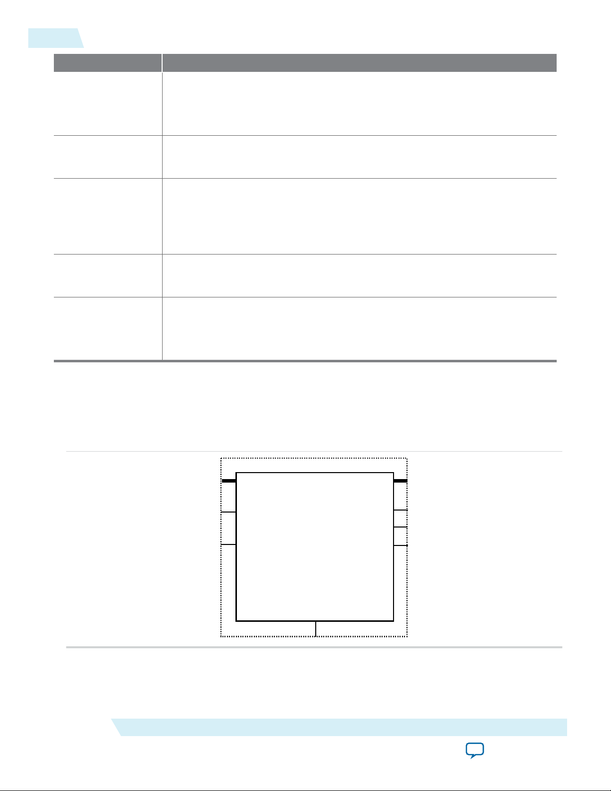
data[]
clk_en
clock
inst
ALTFP_INV_SQRT
result[]
zero
nan
division_by_zero
aclr
11-4
Ports
Time Event
137.5 ns Output value: FFC0 0000h
Exception handling ports: nan asserts
The inverse square root of a negative value produces a NaN.
20 ns data[] value: 0000 0004h
The is a denormal value.
147.5 ns Output value: 7F80 0000h
Denormal numbers are forced-zero values, therefore the inverse square root of zero
results in infinity.
Exception handling ports: nan deasserts, division_by_zero asserts
50 ns data[] value: 7F80 0000h
This is an infinity value.
177.5 ns Output value: 0000 0000h
UG-01058
2014.12.19
The inverse square root of an infinity value produces a zero.
Exception handling ports: zero asserts
Ports
Figure 11-3: ALTFP_INV_SQRT Signals
Altera Corporation
ALTFP_INV_SQRT IP Core
Send Feedback
Page 91

UG-01058
2014.12.19
Table 11-5: ALTFP_INV_SQRT IP Core Input Signals
Port Name Required Description
aclr No Asynchronous clear. When the aclr port is asserted high, the
clk_en No Clock enable. When the clk_en port is asserted high, an
clock Yes Clock input to the megafunction.
data[] Yes Floating-point input data. The MSB is the sign bit, the next
Table 11-6: ALTFP_INV_SQRT IP Core Output Signals
Port Name Required Description
result[] Yes The floating-point inverse result of the value at the data[]
Parameters
function is asynchronously cleared.
inversion value operation takes place. When signal is asserted
low, no operation occurs and the outputs remain unchanged.
MSBs are the exponent, and the LSBs are the mantissa. This
input port size is the total width of the sign bit, exponent bits,
and mantissa bits.
input port. The MSB is the sign bit, the next MSBs are the
exponent, and the LSBs are the mantissa. The size of this port is
the total width of the sign bit, exponent bits, and mantissa bits.
11-5
zero No Zero exception output. Asserted when the value at the
result[] port is a zero.
division_by_zero No Division-by-zero exception output. Asserted when the
denominator input is a zero.
nan No NaN exception output. Asserted when an invalid inversion of
square root occurs, such as the square root of a negative
number. In this case, a NaN value is output to the result[]
output port. Any operation involving a NaN will also produce a
NaN.
Parameters
ALTFP_INV_SQRT IP Core
Send Feedback
Altera Corporation
Page 92

11-6
Parameters
Table 11-7: ALTFP_INV_SQRT Megafunction Parameters
Parameter Name Type Required Description
WIDTH_EXP Integer Yes Specifies the precision of the exponent. If this
parameter is not specified, the default is 8. The bias
of the exponent is always set to 2
that is, 127 for the single-precision format and 1023
for the double-precision format. The value of the
WIDTH_EXP parameter must be 8 for the single-
precision format, 11 for the double-precision
format, and a minimum of 11 for the singleextended precision format. The value of the WIDTH_
EXP parameter must be less than the value of the
WIDTH_MAN parameter, and the sum of the WIDTH_
EXP and WIDTH_MAN parameters must be less than
64.
(WIDTH_EXP -1)
UG-01058
2014.12.19
-1,
WIDTH_MAN
Integer Yes Specifies the value of the mantissa. If this parameter
is not specified, the default is 23. When the WIDTH_
EXP parameter is 8 and the floating-point format is
single-precision, the WIDTH_MAN parameter value
must be 23. Otherwise, the value of the WIDTH_MAN
parameter must be a minimum of 31. The value of
the WIDTH_MAN parameter must be greater than the
value of the WIDTH_EXP parameter. The sum of the
WIDTH_EXP and WIDTH_MAN parameters must be less
than 64.
PIPELINE Integer Yes Specifies the amount of latency, expressed in clock
cycles, used in the ALTFP_INV_SQRT megafunc‐
tion. Create the ALTFP_INV_SQRT megafunction
with the MegaWizard Plug-In Manager to calculate
the value for this parameter.
ROUNDING String No Specifies the rounding mode. The default value is
TO_NEAREST. Other rounding modes are not
supported.
Altera Corporation
ALTFP_INV_SQRT IP Core
Send Feedback
Page 93

2014.12.19
www.altera.com
101 Innovation Drive, San Jose, CA 95134
ALTFP_LOG
12
UG-01058
Subscribe
Send Feedback
You can use the ports and parameters available to customize the ALTFP_LOG IP core according to your
application.
ALTFP_LOG Features
The ALTFP_LOG IP core offers the following features:
• Natural logarithm functions.
• Optional exception handling output ports such as zero and nan.
Output Latency
The output latency options for the ALTFP_LOG megafunction differs depending on the precision
selected, the width of the mantissa, or both.
Table 12-1: Latency Options for Each Precision Format
Precision Mantissa Width Latency (in clock cycles)
Single 23 21
Double 52 34
31–36 25
37–42 28
Single Extended
43–48 31
49–52 34
ALTFP_LOG Truth Table
This table lists the truth table for the natural logarithm operation.
©
2014 Altera Corporation. All rights reserved. ALTERA, ARRIA, CYCLONE, ENPIRION, MAX, MEGACORE, NIOS, QUARTUS and STRATIX words and logos are
trademarks of Altera Corporation and registered in the U.S. Patent and Trademark Office and in other countries. All other words and logos identified as
trademarks or service marks are the property of their respective holders as described at www.altera.com/common/legal.html. Altera warrants performance
of its semiconductor products to current specifications in accordance with Altera's standard warranty, but reserves the right to make changes to any
products and services at any time without notice. Altera assumes no responsibility or liability arising out of the application or use of any information,
product, or service described herein except as expressly agreed to in writing by Altera. Altera customers are advised to obtain the latest version of device
specifications before relying on any published information and before placing orders for products or services.
ISO
9001:2008
Registered
Page 94

12-2
ALTFP_LOG Resource Utilization and Performance
Table 12-2: Truth Table for Natural Logarithm Operations
DATA[] SIGN BIT RESULT[] Zero NaN
Normal 0 Normal 0 0
Normal 1 NaN
(7)
1
Denormal
(9)
Zero
(8)
0 Zero 1 0
0 Negative Infinity 0 0
0/1 Negative Infinity 0 0
(6)
Infinity 0 Positive Infinity 1 0
NaN X NaN 0 1
ALTFP_LOG Resource Utilization and Performance
This table lists the resource utilization and performance information for the ALTFP_LOG IP core. The
information was derived using the Quartus II software version 10.0.
UG-01058
2014.12.19
0 1
Table 12-3: ALTFP_LOG Resource Utilization and Performance for Stratix IV Devices
Logic usage
Device Family Precision
Output
Latency
Adaptive
Look-Up
Tables
(ALUTs)
Dedicated
Logic
Registers
(DLRs)
Adaptive
Logic
Modules
(ALMs)
18-Bit DSP
f
MAX
Single 21 1,950 1,864 1,378 8 385
Stratix IV
Double 34 5,451 6,031 4,151 64 211
ALTFP_LOG Design Example: Natural Logarithm of Single-Precision Format Numbers
This design example uses the ALTFP_LOG IP core to compute the natural logarithm of single-precision
format numbers. This example uses the parameter editor GUI to define the core.
(6)
The natural logarithm of a negative value is invalid. Therefore, the output produced is a NaN.
(7)
The “1” in this case is equivalent to In 1.
(8)
The value of positive denormalized numbers is a value that approximates zero, and the output produced is a
negative infinity number.
(9)
The zero in this case represents zero special case of the IEEE standard. It is not equivalent to In 0, but
instead approximates to it.
(MHz)
Altera Corporation
ALTFP_LOG
Send Feedback
Page 95
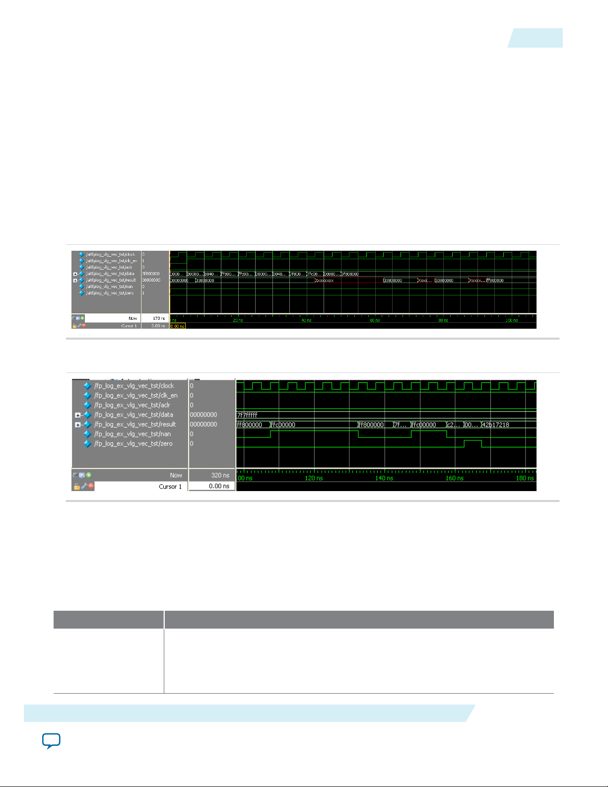
UG-01058
2014.12.19
Related Information
ALTFP_LOG Design Example: Understanding the Simulation Results
• Floating-Point IP Cores Design Example Files on page 1-16
• Floating-Point IP Cores Design Examples
Provides the design example files for the Floating-Point IP cores
• ModelSim-Altera Software Support
Provides information about installation, usage, and troubleshooting
ALTFP_LOG Design Example: Understanding the Simulation Results
The simulation waveform in this design example is not shown in its entirety. Run the design example files
in the ModelSim-Altera software to see the complete simulation waveforms.
These figures show the expected simulation results in the ModelSim-Altera software.
Figure 12-1: ALTFP_LOG ModelSim Simulation Waveform (Input Data)
12-3
Figure 12-2: ALTFP_LOG ModelSim Simulation Waveform (Output Data)
This design example includes the input of special cases to show the exception handling of the IP core,
such as the smallest valid input and the input value of “1”.
In this example, the output delay is set to 21 clock cycles. Therefore, the result is only shown at the output
port after the 21st clock cycle at 102.5 ns.
Table 12-4: Summary of Input Values and Corresponding Outputs
This table lists the inputs and corresponding outputs obtained from the simulation in the waveforms.
Time Event
0 ns, start-up data[] value: 0000 0000h
ALTFP_LOG
Send Feedback
Output value: An undefined value is seen on the result[] port, which is ignored.
All values seen on the output port before the 21st clock cycle are merely due to the
behavior of the system during start-up and should be disregarded.
Altera Corporation
Page 96

12-4
Signals
Time Event
102.5 ns Output value: FF80 0000h
The natural logarithm of zero is negative infinity.
5 ns data[] value: 8000 0000h
This is a negative number.
107.5 ns Output value: FFC0 0000h
Exception handling ports: nan asserts
The natural logarithm of a negative value is invalid. Therefore, the output produced
is a NaN.
30 ns data[] value: 0040 0000h
The is a denormal value.
132.5 ns Output value: FF80 0000h
As denormal numbers are not supported, the input is forced to zero before going
through the logarithm function. The natural logarithm of zero is negative infinity.
UG-01058
2014.12.19
45 ns data[] value: 0080 0000h
This is the smallest valid input. All the input bits are 0 except the LSB of the
exponent field.
147.5 ns Output value: C2AE AC50h
60 ns data[] value: 3F80 0000h
The input value 3F80 0000h is equivalent to the actual value,
1.0 × 20 = 1.
152.5 ns Output value: 0000 0000h
Exception handling ports: zero asserts
Since In 1 results in zero, it produces an output of zero.
Signals
Altera Corporation
ALTFP_LOG
Send Feedback
Page 97

data[]
clk_en
clock
inst
ALTFP_LOG
result[]
zero
nan
aclr
UG-01058
2014.12.19
Figure 12-3: ALTFP_LOG Signals
Table 12-5: ALTFP_LOG IP Core Input Signals
Port Name Required Description
Signals
12-5
aclr No Asynchronous clear. When the aclr port is asserted high, the
function is asynchronously cleared.
clk_en No
Clock enable. When the clk_en port is asserted high, a natural
logarithm operation takes place. When signal is asserted low, no
operation occurs and the outputs remain unchanged.
Deasserting clk_en halts operation until it is asserted again. Assert
the clk_en signal for the number of clock cycles equivalent to the
required output latency (PIPELINE parameter value) for the results
to be shown at the output.
clock Yes Clock input to the IP core.
data[] Yes
Floating-point input data. The MSB is the sign bit, the next MSBs
are the exponent, and the LSBs are the mantissa. This input port size
is the total width of the sign bit, exponent bits, and mantissa bits.
For single precision, the width is fixed to 32 bits. For double
precision, the width is fixed to 64 bits. For single extended
precision, you can choose a width in the range from 43 to 64 bits.
Table 12-6: ALTFP_LOG IP Core Output Signals
Port Name Required Description
result[] Yes The natural logarithm of the value on input data. The natural
logarithm of the data[] input port, shown in floating-point format.
The widths of the result[] output port and data[] input port are
the same.
ALTFP_LOG
Altera Corporation
Send Feedback
Page 98

12-6
Parameters
Port Name Required Description
zero No Zero exception output. Asserted when the exponent and mantissa
of the output port are zero. This occurs when the actual input value
is 1 because ln 1 = 0.
nan No NaN exception output. Asserted when the exponent and mantissa
of the output port are all 1’s and non-zero, respectively. This occurs
when the input is a negative number or NaN.
Parameters
Table 12-7: ALTFP_LOG Megafunction Parameters
Parameter Name Type Required Description
WIDTH_EXP Integer Yes Specifies the precision of the exponent. If this
parameter is not specified, the default is 8. The bias
of the exponent is always set to 2
that is, 127 for the single-precision format and 1023
for the double-precision format. The value of the
WIDTH_EXP parameter must be 8 for the single-
precision format, 11 for the double-precision
format, and a minimum of 11 for the singleextended precision format. The value of the WIDTH_
EXP parameter must be less than the value of the
WIDTH_MAN parameter, and the sum of the WIDTH_
EXP and WIDTH_MAN parameters must be less than
64.
(WIDTH_EXP -1)
UG-01058
2014.12.19
-1,
WIDTH_MAN
PIPELINE Integer Yes Specifies the amount of latency in clock cycles used
Altera Corporation
Integer Yes Specifies the precision of the mantissa. If this
parameter is not specified, the default is 23. The
value of WIDTH_MAN must be 23 for the singleprecision format, and 52 for the double-precision
format. For the single-extended precision format,
the valid value ranges from 31 to 52. The value of
WIDTH_MAN must be greater than the value of WIDTH_
EXP, and the sum of WIDTH_EXP and WIDTH_MAN
must be less than 64.
in the ALTFP_LOG megafunction. Create the
ALTFP_LOG megafunction with the MegaWizard
Plug-In Manager to calculate the value for this
parameter.
ALTFP_LOG
Send Feedback
Page 99

2014.12.19
www.altera.com
101 Innovation Drive, San Jose, CA 95134
ALTFP_ATAN IP Core
13
UG-01058
Subscribe
You can use the ports and parameters available to customize the ALTFP_ATAN megafunction according
to your application.
Output Latency
The output latency option for the ALTFP_ATAN megafunction have a fixed latency level for singleprecision format.
Table 13-1: Latency Option
Trigonometric Function Precision Mantissa Width Latency (in clock cycles)
Arctangent Single 23 34
ALTFP_ATAN Features
The ALTFP_ATAN IP core offers the following features:
Send Feedback
• Arctangent value of a given angle, θ in unit radian.
• Support for single-precision floating point format.
• Support for optional input ports such as asynchronous clear (aclr) and clock enable (clk_en) ports.
ALTFP_ATAN Resource Utilization and Performance
This table lists the resource utilization and performance information for the ALTFP_ATAN IP core. The
information was derived using the Quartus II software version 11.0.
©
2014 Altera Corporation. All rights reserved. ALTERA, ARRIA, CYCLONE, ENPIRION, MAX, MEGACORE, NIOS, QUARTUS and STRATIX words and logos are
trademarks of Altera Corporation and registered in the U.S. Patent and Trademark Office and in other countries. All other words and logos identified as
trademarks or service marks are the property of their respective holders as described at www.altera.com/common/legal.html. Altera warrants performance
of its semiconductor products to current specifications in accordance with Altera's standard warranty, but reserves the right to make changes to any
products and services at any time without notice. Altera assumes no responsibility or liability arising out of the application or use of any information,
product, or service described herein except as expressly agreed to in writing by Altera. Altera customers are advised to obtain the latest version of device
specifications before relying on any published information and before placing orders for products or services.
ISO
9001:2008
Registered
Page 100

13-2
Ports
Table 13-2: ALTFP_ATAN Resource Utilization and Performance
UG-01058
2014.12.19
Logic usage
Device Family Function Precision
Output
Latency
Adaptive
Look-Up
Tables
(ALUTs)
Dedicate
d Logic
Registers
(DLRs)
Adaptive
Logic
Modules
(ALMs)
18-Bit
DSP
Stratix V ArcTangentSingle 36 2,454 1,010 1,303 27 255.49
Ports
Table 13-3: ALTFP_ATAN Megafunction Input Ports
Port Name Required Description
aclr No Asynchronous clear. When the aclr port is asserted high, the
function is asynchronously cleared.
clk_en No Clock enable. When the clk_en port is asserted high, division
takes place. When the signal is deasserted, no operation occurs
and the outputs remain unchanged.
clock Yes Clock input to the megafunction.
f
MAX
(MHz)
data[] Yes Floating-point input data. The MSB is the sign bit, the next MSBs
are the exponent, and the LSBs are the mantissa. This input port
size is the total width of the sign bit, exponent bits, and mantissa
bits.
Port Name Required Description
result[] Yes The result of the trigonometric function in floating-point format.
The widths of the result[] output port and data[] input port
are the same.
ALTFP_ATAN Parameters
Altera Corporation
ALTFP_ATAN IP Core
Send Feedback
 Loading...