

Page 1

Asynchronous Serial Interface (ASI) MegaCore Function
User Guide
Asynchronous Serial Interface (ASI) MegaCore Function
User Guide
101 Innovation Drive
San Jose, CA 95134
www.altera.com
c The ASI MegaCore function is scheduled for product obsolescence and discontinued
support as described in PDN1306. Therefore, Altera does not recommend use of this IP
in new designs. For more information about Altera’s current IP offering, refer to Altera’s
Intellectual Property website.
UG-ASI0106-13.1
Document last updated for Altera Complete Design Suite version:
Document publication date:
January 2014
Feedback
13.1
Subscribe
Page 2

© 2014 Altera Corporation. All rights reserved. ALTERA, ARRIA, CYCLONE, HARDCOPY, MAX, MEGACORE, NIOS, QUARTUS and STRATIX are Reg. U.S. Pat.
& Tm. Off. and/or trademarks of Altera Corporation in the U.S. and other countries. All other trademarks and service marks are the property of their respective
holders as described at www.altera.com/common/legal.html. Altera warrants performance of its semiconductor products to current specifications in accordance
with Altera’s standard warranty, but reserves the right to make changes to any products and services at any time without notice. Altera assumes no responsibility or
liability arising out of the application or use of any information, product, or service described herein except as expressly agreed to in writing by Altera. Altera
customers are advised to obtain the latest version of device specifications before relying on any published information and before placing orders for products or
services.
Asynchronous Serial Interface (ASI) MegaCore Function User Guide January 2014 Altera Corporation
Page 3

Contents
Chapter 1. About This MegaCore Function
Release Information . . . . . . . . . . . . . . . . . . . . . . . . . . . . . . . . . . . . . . . . . . . . . . . . . . . . . . . . . . . . . . . . . . . . . 1–1
Device Family Support . . . . . . . . . . . . . . . . . . . . . . . . . . . . . . . . . . . . . . . . . . . . . . . . . . . . . . . . . . . . . . . . . . . 1–1
Features . . . . . . . . . . . . . . . . . . . . . . . . . . . . . . . . . . . . . . . . . . . . . . . . . . . . . . . . . . . . . . . . . . . . . . . . . . . . . . . . 1–2
General Description . . . . . . . . . . . . . . . . . . . . . . . . . . . . . . . . . . . . . . . . . . . . . . . . . . . . . . . . . . . . . . . . . . . . . 1–2
MegaCore Verification . . . . . . . . . . . . . . . . . . . . . . . . . . . . . . . . . . . . . . . . . . . . . . . . . . . . . . . . . . . . . . . . . . . 1–2
Resource Utilization . . . . . . . . . . . . . . . . . . . . . . . . . . . . . . . . . . . . . . . . . . . . . . . . . . . . . . . . . . . . . . . . . . . . . 1–3
Installation and Licensing . . . . . . . . . . . . . . . . . . . . . . . . . . . . . . . . . . . . . . . . . . . . . . . . . . . . . . . . . . . . . . . . 1–3
OpenCore Plus Evaluation . . . . . . . . . . . . . . . . . . . . . . . . . . . . . . . . . . . . . . . . . . . . . . . . . . . . . . . . . . . . . 1–4
OpenCore Plus Time-Out Behavior . . . . . . . . . . . . . . . . . . . . . . . . . . . . . . . . . . . . . . . . . . . . . . . . . . . . . . 1–5
Chapter 2. Getting Started
Design Flow . . . . . . . . . . . . . . . . . . . . . . . . . . . . . . . . . . . . . . . . . . . . . . . . . . . . . . . . . . . . . . . . . . . . . . . . . . . . 2–1
Specify Parameters . . . . . . . . . . . . . . . . . . . . . . . . . . . . . . . . . . . . . . . . . . . . . . . . . . . . . . . . . . . . . . . . . . . . 2–1
Simulate the Design . . . . . . . . . . . . . . . . . . . . . . . . . . . . . . . . . . . . . . . . . . . . . . . . . . . . . . . . . . . . . . . . . . . 2–3
Simulate with IP Functional Simulation Models . . . . . . . . . . . . . . . . . . . . . . . . . . . . . . . . . . . . . . . . 2–3
Simulate with the ModelSim Simulator . . . . . . . . . . . . . . . . . . . . . . . . . . . . . . . . . . . . . . . . . . . . . . . . 2–4
Simulating in Third-Party Simulation Tools Using NativeLink . . . . . . . . . . . . . . . . . . . . . . . . . . . . 2–4
Compile the Design and Program a Device . . . . . . . . . . . . . . . . . . . . . . . . . . . . . . . . . . . . . . . . . . . . . . . . . 2–5
Chapter 3. Parameter Settings
Chapter 4. Functional Description
Transmitter . . . . . . . . . . . . . . . . . . . . . . . . . . . . . . . . . . . . . . . . . . . . . . . . . . . . . . . . . . . . . . . . . . . . . . . . . . . . . 4–1
8B10B Encoder . . . . . . . . . . . . . . . . . . . . . . . . . . . . . . . . . . . . . . . . . . . . . . . . . . . . . . . . . . . . . . . . . . . . . . . . 4–1
Transceiver . . . . . . . . . . . . . . . . . . . . . . . . . . . . . . . . . . . . . . . . . . . . . . . . . . . . . . . . . . . . . . . . . . . . . . . . . . 4–1
Serializer . . . . . . . . . . . . . . . . . . . . . . . . . . . . . . . . . . . . . . . . . . . . . . . . . . . . . . . . . . . . . . . . . . . . . . . . . . 4–2
GX Transceivers . . . . . . . . . . . . . . . . . . . . . . . . . . . . . . . . . . . . . . . . . . . . . . . . . . . . . . . . . . . . . . . . . . . . 4–2
Receiver . . . . . . . . . . . . . . . . . . . . . . . . . . . . . . . . . . . . . . . . . . . . . . . . . . . . . . . . . . . . . . . . . . . . . . . . . . . . . . . . 4–2
Transceiver . . . . . . . . . . . . . . . . . . . . . . . . . . . . . . . . . . . . . . . . . . . . . . . . . . . . . . . . . . . . . . . . . . . . . . . . . . 4–2
Deserializer . . . . . . . . . . . . . . . . . . . . . . . . . . . . . . . . . . . . . . . . . . . . . . . . . . . . . . . . . . . . . . . . . . . . . . . . 4–3
GX Transceiver . . . . . . . . . . . . . . . . . . . . . . . . . . . . . . . . . . . . . . . . . . . . . . . . . . . . . . . . . . . . . . . . . . . . . 4–3
Oversampling Interface . . . . . . . . . . . . . . . . . . . . . . . . . . . . . . . . . . . . . . . . . . . . . . . . . . . . . . . . . . . . . . . . 4–3
Word Aligner . . . . . . . . . . . . . . . . . . . . . . . . . . . . . . . . . . . . . . . . . . . . . . . . . . . . . . . . . . . . . . . . . . . . . . . . 4–3
8B10B Decoder . . . . . . . . . . . . . . . . . . . . . . . . . . . . . . . . . . . . . . . . . . . . . . . . . . . . . . . . . . . . . . . . . . . . . . . 4–3
Synchronization State Machine . . . . . . . . . . . . . . . . . . . . . . . . . . . . . . . . . . . . . . . . . . . . . . . . . . . . . . . . . 4–4
Packet Synchronization . . . . . . . . . . . . . . . . . . . . . . . . . . . . . . . . . . . . . . . . . . . . . . . . . . . . . . . . . . . . . . . . 4–4
Testbench . . . . . . . . . . . . . . . . . . . . . . . . . . . . . . . . . . . . . . . . . . . . . . . . . . . . . . . . . . . . . . . . . . . . . . . . . . . . . . 4–5
Signals . . . . . . . . . . . . . . . . . . . . . . . . . . . . . . . . . . . . . . . . . . . . . . . . . . . . . . . . . . . . . . . . . . . . . . . . . . . . . . . . . 4–5
Appendix A. Constraints
Introduction . . . . . . . . . . . . . . . . . . . . . . . . . . . . . . . . . . . . . . . . . . . . . . . . . . . . . . . . . . . . . . . . . . . . . . . . . . . A–1
Constraint Design With TimeQuest Timing Analyzer . . . . . . . . . . . . . . . . . . . . . . . . . . . . . . . . . . . . . . . A–1
Specify Clock Characteristics . . . . . . . . . . . . . . . . . . . . . . . . . . . . . . . . . . . . . . . . . . . . . . . . . . . . . . . . A–2
Define the Setup and Hold Relationship between the 135-MHz Clocks and the 337.5-MHz
zero-degree Clocks . . . . . . . . . . . . . . . . . . . . . . . . . . . . . . . . . . . . . . . . . . . . . . . . . . . . . . . . . . . . . . . . A–2
Specify Clocks that are Exclusive or Asynchronous . . . . . . . . . . . . . . . . . . . . . . . . . . . . . . . . . . . . . A–3
Minimize Timing Skew . . . . . . . . . . . . . . . . . . . . . . . . . . . . . . . . . . . . . . . . . . . . . . . . . . . . . . . . . . . . . . . . . A–3
January 2014 Altera Corporation Asynchronous Serial Interface (ASI) MegaCore Function User Guide
Page 4

iv ContentsContents
Additional Information
Document Revision History . . . . . . . . . . . . . . . . . . . . . . . . . . . . . . . . . . . . . . . . . . . . . . . . . . . . . . . . . . . Info–1
How to Contact Altera . . . . . . . . . . . . . . . . . . . . . . . . . . . . . . . . . . . . . . . . . . . . . . . . . . . . . . . . . . . . . . . . Info–1
Typographic Conventions . . . . . . . . . . . . . . . . . . . . . . . . . . . . . . . . . . . . . . . . . . . . . . . . . . . . . . . . . . . . . Info–2
Asynchronous Serial Interface (ASI) MegaCore Function User Guide January 2014 Altera Corporation
Page 5
The Altera® Asynchronous Serial Interface (ASI) MegaCore® function implements a
receiver or transmitter digital video broadcast asynchronous serial interface
(DVB-ASI) that transports MPEG-2 packets over copper-based cables or optical
networks. DVB-ASI is used as a serial link between equipment in broadcast facilities.
Release Information
Tab le 1– 1 provides information about this release of the ASI MegaCore function.
Table 1–1. Release Information
Version 13.1
Release Date November 2013
Ordering Code IP-ASI
Product ID 00B9
Vendor ID 6AF7
1. About This MegaCore Function
Item Description
f For more information about this release, refer to the MegaCore IP Library Release Notes
and Errata.
Altera verifies that the current version of the Quartus
previous version of each MegaCore function. The MegaCore IP Library Release Notes
and Errata report any exceptions to this verification. Altera does not verify
compilation with MegaCore function versions older than one release.
Device Family Support
MegaCore functions provide the following support for Altera device families:
■ Preliminary support—Altera verifies the IP core with preliminary timing models for
this device family. The core meets all functional requirements, but might still be
undergoing timing analysis for the device family. It can be used in production
designs with caution.
■ Final support—Altera verifies the IP core with final timing models for this device
family. The core meets all functional and timing requirements for the device family
and can be used in production designs.
Tab le 1– 2 shows the level of support offered by the ASI MegaCore function to each
Altera device family.
Table 1–2. Device Family Support (Part 1 of 2)
®
II software compiles the
Device Family Support
®
II GX Preliminary
Arria
®
Cyclone
January 2014 Altera Corporation Asynchronous Serial Interface (ASI) MegaCore Function User Guide
III Final
Page 6

1–2 Chapter 1: About This MegaCore Function
Table 1–2. Device Family Support (Part 2 of 2)
Device Family Support
Cyclone III LS (1) Preliminary
Cyclone IV GX (2) Preliminary
Cyclone IV E (1.2V) Preliminary
®
III (1) Final
Stratix
Stratix IV (3) Final
Other device families No support
Notes to Table 1–2:
(1) The Cyclone series of devices and the Stratix III devices only support soft SERDES.
(2) Cyclone IV GX support includes all density in the device family except the EP4CGX15, EP4CGX22, and EP4CGX30
(excluding the EP4CGX30F484 pin package) devices.
(3) Stratix IV GT only supports soft logic mode.
Features
Features
This section summarizes the features of the ASI MegaCore function.
■ IP functional simulation models for use in Altera-supported VHDL and Verilog
HDL simulators
■ Easy-to-use MegaWizard
■ Support for OpenCore Plus evaluation
General Description
The ASI MegaCore function demonstrates how to transmit or receive packets over an
ASI. The ASI MegaCore function works with 270 megabits per second (Mbps) DVBASI, as defined by the DVB-ASI specification EN 50083-9 from CENELEC / December
2002 “Cable networks for television signals, sound signals and interactive services. Part 9:
Interfaces for CATV/SMATV head-ends and similar professional equipment for DVB/MPEG2
transport streams”.
f For information on ASI MegaCore function demonstration on the Altera Cyclone
Video Demonstration Board, refer to the Cyclone Video Demonstration Board Data Sheet.
MegaCore Verification
The ASI MegaCore verification involves the testing of the DVB-ASI specification
EN 50083-9 from CENELEC / December 2002 “Cable networks for television signals, sound
signals and interactive services. Part 9: Interfaces for CATV/SMATV head-ends and similar
professional equipment for DVB/MPEG2 transport streams”.
TM
interface
Asynchronous Serial Interface (ASI) MegaCore Function User Guide January 2014 Altera Corporation
Page 7

Chapter 1: About This MegaCore Function 1–3
Resource Utilization
Resource Utilization
Tab le 1– 3 shows estimated resource usage for the ASI MegaCore function, with the
Quartus II software version 13.1.
Table 1–3. Resource Usage
Device Family Parameters LEs
Cyclone III
Cyclone III LS
Cyclone IV GX
Stratix III
Stratix IV
Installation and Licensing
The ASI MegaCore function is part of the MegaCore IP Library, which is distributed
with the Quartus II software and downloadable from the Altera website,
www.altera.com.
f For system requirements and installation instructions, refer to Altera Software
Installation & Licensing.
Combinational
ALUTs
Receiver 577 — —
Transmitter 78 — —
Receiver 587 — —
Transmitter 78 — —
Receiver 564 — —
Transmitter 78 — —
Receiver — 321 241
Transmitter — 47 49
Receiver — 328 191
Transmitter — 65 62
Logic
Registers
January 2014 Altera Corporation Asynchronous Serial Interface (ASI) MegaCore Function User Guide
Page 8
1–4 Chapter 1: About This MegaCore Function
example
Contains an example design, see AN 344: ASI Demonstration.
ip
Contains the Altera MegaCore IP Library and third-party IP cores.
<path>
Installation directory.
altera
Contains the Altera MegaCore IP Library.
common
Contains shared components.
asi
Contains the ASI MegaCore function files.
lib
Contains encrypted lower-level design files and other support files.
simulation
Contains simulation files.
asi_mc_build
Contains the MegaCore function function files for the testbench.
ts_packet_gen
Contains the TS packet generator files for the testbench.
modelsim
Contains the Altera MegaCore IP Library and third-party IP cores.
modelsim
Contains the Modelsim simulation files.
testbench
Contains the testbench files.
quartus
Contains the Quartus II NativeLink project.
Installation and Licensing
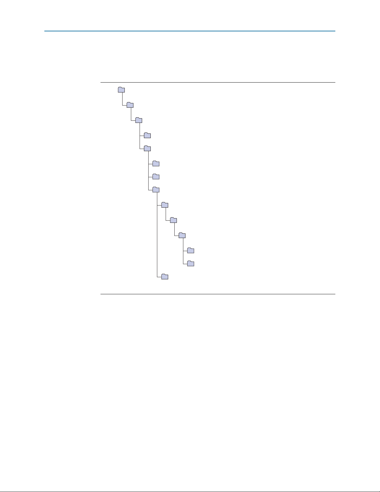
Figure 1–1 on page 1–4 shows the directory structure after you install the ASI
MegaCore function, where
<
path> is the installation directory. The default installation
directory on Windows is c:\altera\<version>; on Linux it is /opt/altera<version>.
Figure 1–1. Directory Structure
Asynchronous Serial Interface (ASI) MegaCore Function User Guide January 2014 Altera Corporation
OpenCore Plus Evaluation
You need to obtain a license for the MegaCore function only when you are completely
satisfied with its functionality and performance, and want to take your design to
production.
After you obtain a license for ASI, you can request a license file from the Altera web
site at www.altera.com/licensing and install it on your computer. When you request a
license file, Altera emails you a license.dat file. If you do not have Internet access,
contact your local Altera representative.
With Altera’s free OpenCore Plus evaluation feature, you can perform the following
actions:
■ Simulate the behavior of a megafunction (Altera MegaCore function or AMPP
megafunction) within your system
■ Verify the functionality of your design, as well as evaluate its size and speed
quickly and easily
SM
Page 9

Chapter 1: About This MegaCore Function 1–5
Installation and Licensing
■ Generate time-limited device programming files for designs that include
megafunctions
■ Program a device and verify your design in hardware
You only need to obtain a license for the megafunction when you are completely
satisfied with its functionality and performance, and want to take your design to
production.
f For more information on OpenCore Plus hardware evaluation using the ASI, refer to
AN 320: OpenCore Plus Evaluation of Megafunctions.
OpenCore Plus Time-Out Behavior
OpenCore Plus hardware evaluation can support the following two modes of
operation:
■ Untethered—the design runs for a limited time
■ Tethered—requires a connection between your board and the host computer. If
tethered mode is supported by all megafunctions in a design, the device can
operate for a longer time or indefinitely
All megafunctions in a device time out simultaneously when the most restrictive
evaluation time is reached. If there is more than one megafunction in a design, a
specific megafunction’s time-out behavior may be masked by the time-out behavior of
the other megafunctions.
1 For MegaCore functions, the untethered time-out is 1 hour; the tethered time-out
value is indefinite.
Your design stops working after the hardware evaluation time expires and the
rst
signal goes high.
January 2014 Altera Corporation Asynchronous Serial Interface (ASI) MegaCore Function User Guide
Page 10

Design Flow
Compile Design
Program Device
Specify Parameters
Simulate with
Testbench
Instantiate Core
Into Design
Specify
Constraints
2. Getting Started
Figure 2–1 shows the stages for creating a system with the ASI MegaCore function
and the Quartus II software. The sections in this chapter describe each stage.
Figure 2–1. Design Flow
The design flow allows you to customize the ASI MegaCore function using the ASI
parameter editor in the MegaWizard Plug-In Manager and the Quartus II software.
When you finish generating a custom variation of the ASI MegaCore function, you
can manually integrate it into your design.
f For more information about the MegaWizard Plug-In Manager, refer to the Quartus II
Help.
Specify Parameters
To specify the parameters for your MegaCore function, follow these steps:
1. In the Quartus II software, create a new Quartus II project with the New Project
Wizard.
2. On the Tools menu click MegaWizard Plug-In Manager and follow the steps to
start the MegaWizard Plug-In Manager.
January 2014 Altera Corporation Asynchronous Serial Interface (ASI) MegaCore Function User Guide
Page 11

2–2 Chapter 2: Getting Started
Design Flow
1 The ASI MegaCore function is in the Interface > ASI directory.
3. Specify the parameters on all pages in the Parameter Settings tab.
f For detailed explanation of the parameters, refer to the “Parameter
Settings” on page 3–1.
4. On the EDA tab, turn on Generate simulation model to generate an IP functional
simulation model for the MegaCore function.
An IP functional simulation model is a cycle-accurate VHDL or Verilog HDL
model produced by the Quartus II software.
c Use the simulation models only for simulation and not for synthesis or any
other purposes. Using these models for synthesis creates a nonfunctional
design.
1 Some third-party synthesis tools can use a netlist that contains only the
structure of the MegaCore function, but not detailed logic, to optimize
performance of the design that contains the MegaCore function. If your
synthesis tool supports this feature, turn on Generate netlist.
5. On the Summary tab, select the files you want to generate. A gray checkmark
indicates a file that is automatically generated. All other files are optional.
f For more information about the files generated in your project directory,
refer to Ta bl e 2– 1.
6. Click Finish to generate the MegaCore function and supporting files.
7. If you generate the MegaCore function instance in a Quartus II project, you are
prompted to add the .qip files to the current Quartus II project.
1 The .qip file is generated by the MegaWizard interface, and contains
information about the generated IP core. In most cases, the .qip file contains
all of the necessary assignments and information required to process the
MegaCore function or system in the Quartus II compiler. The MegaWizard
interface generates a single .qip file for each MegaCore function.
8. After you review the generation report, click Exit to close the MegaWizard Plug-In
Manager.
Asynchronous Serial Interface (ASI) MegaCore Function User Guide January 2014 Altera Corporation
Page 12

Chapter 2: Getting Started 2–3
Design Flow
Tab le 2– 1 describes the generated files and other files that may be in your project
directory. The names and types of files specified in the summary vary based on
whether you created your design with VHDL or Verilog HDL.
Table 2–1. Generated Files
File Name Description
A MegaCore function variation file, which defines a VHDL or Verilog HDL
<variation name>.v or .vhd
<variation name>.cmp
<variation name>.bsf
<variation name>.html MegaCore function report file.
<variation name>.ppf
<variation name>.vo or .vho VHDL or Verilog HDL IP functional simulation model.
<variation name>_bb.v
<variation name>.qip Contains Quartus II project information for your MegaCore function variations.
description of the custom MegaCore function. Instantiate the entity defined by
this file inside of your design. Include this file when compiling your design in
the Quartus II software.
A VHDL component declaration file for the MegaCore function variation. Add
the contents of this file to any VHDL architecture that instantiates the
MegaCore function.
Quartus II symbol file for the MegaCore function variation. You can use this file
in the Quartus II block diagram editor.
This XML file describes the MegaCore pin attributes to the Quartus II Pin
Planner. MegaCore pin attributes include pin direction, location, I/O standard
assignments, and drive strength. If you launch IP Toolbench outside of the Pin
Planner application, you must explicitly load this file to use Pin Planner.
A Verilog HDL black-box file for the MegaCore function variation. Use this file
when using a third-party EDA tool to synthesize your design.
You can now integrate your custom MegaCore function variation into your design
and simulate and compile.
Simulate the Design
This section describes the following simulation techniques:
■ Simulate with IP Functional Simulation Models
■ Simulate with the ModelSim Simulator
■ Simulating in Third-Party Simulation Tools Using NativeLink
Simulate with IP Functional Simulation Models
You can simulate your design using the MegaWizard-generated VHDL and Verilog
HDL IP functional simulation models.
You can use the IP functional simulation model with any Altera-supported VHDL or
Verilog HDL simulator. To use the IP functional simulation model, create a suitable
testbench.
f For more information on IP functional simulation models, refer to the Simulating
Altera IP in Third-Party Simulation Tools chapter in volume 3 of the Quartus II Handbook.
January 2014 Altera Corporation Asynchronous Serial Interface (ASI) MegaCore Function User Guide
Page 13

2–4 Chapter 2: Getting Started
Design Flow
Simulate with the ModelSim Simulator
Altera provides a fixed testbench as an example in the simulation\testbench\
directory. The testbench instantiates the design and tests the ASI operation. To use the
testbench with the ModelSim
®
simulator, follow these steps:
1. In a text editor, open the simulation batch file,
simulation\modelsim\modelsim\asi_sim.bat, and edit it to point to your
installation of the ModelSim-Altera simulator.
2. Start the ModelSim-Altera simulator.
3. Run asi_sim.bat in the simulation\modelsim\modelsim directory. This file
compiles the design and starts the ModelSim-Altera simulator. A selection of
signals appears on the waveform viewer. The simulation runs automatically,
providing a pass/fail indication on completion.
Simulating in Third-Party Simulation Tools Using NativeLink
You can perform a simulation in a third-party simulation tool from within the
Quartus II software, using NativeLink.
f For more information on NativeLink, refer to the Simulating Altera IP in Third-Party
Simulation Tools chapter in volume 3 of the Quartus II Handbook.
Altera provides a Quartus II project for use with NativeLink in the
ip\asi\simulation\quartus directory.
To set up simulation in the Quartus II software using NativeLink, follow these steps:
1. On the File menu click Open Project. Browse to the ip\asi\simulation\quartus
directory.
2. Open asi_sim.qpf.
3. Set up the Quartus II NativeLink.
a. On the Assignments menu, click Settings.
b. In the Category list, expand EDA Tool Settings and select Simulation.
c. In To o l na m e list, select a simulation tool.
1 Check that the absolute path to your third-party simulator executable is set.
On the Tools menu, click Options and select EDA Tools Options.
d. Under NativeLink settings, select Compile test bench and click Tes t B e nc he s.
e. Click New in the Test Benches dialog box to create a testbench.
Asynchronous Serial Interface (ASI) MegaCore Function User Guide January 2014 Altera Corporation
Page 14

Chapter 2: Getting Started 2–5
Compile the Design and Program a Device
4. In the New Test Bench Settings dialog box, perform the following steps:
a. In the Test bench name box, type the testbench setup name.
b. In the Top level module in test bench box, type the following as the project
testbench name,
c. In the Design instance in test bench box, type the name of the top-level
instance.
tb_asi_mc
.
d. Under Simulation period, set End simulation at to
e. Add the testbench files. In the File name field, browse to the location of the
testbench, tb_asi_mc, click Open and then click Add.
f. Select the files and click OK.
5. On the Processing menu, point to Start and click Start Analysis & Elaboration.
6. On the Tools menu, point to Run EDA Simulation Tool and click EDA RTL
Simulation.
Compile the Design and Program a Device
You can use the Quartus II software to compile your design. Refer to Quartus II Help
for instructions on performing compilation.
After you have compiled your design, program your targeted Altera device and
verify your design in hardware.
500 µs
.
January 2014 Altera Corporation Asynchronous Serial Interface (ASI) MegaCore Function User Guide
Page 15

Tab le 3– 1 summarizes the parameters.
Table 3–1. Parameters
Parameter Range Description
Currently selected device
family
Interface type Receiver or transmitter
Generate transceiver and protocol
Transceiver and protocol
Use soft logic for
transceiver
blocks, or generate transceiver only,
or generate protocol blocks only
On or off
—
3. Parameter Settings
Shows the device family that you chose in your
Quartus II project.
Select a receiver or transmitter for you custom
variation.
Select the blocks for your custom variation.
For Stratix IV GX devices, specify soft logic for the
transceiver. When you turn on Use soft logic for
transceiver, the transceiver is implemented in the
device’s logic, otherwise the design uses a
Stratix IV GX transceiver.
1 You can change the page that the MegaWizard Plug-In Manager displays by clicking
Next or Back at the bottom of the dialog box. You can move directly to a named page
by clicking the Parameter Settings, EDA, or Summary tab.
January 2014 Altera Corporation Asynchronous Serial Interface (ASI) MegaCore Function User Guide
Page 16

Transmitter
4. Functional Description
The ASI MegaCore function consists of the following elements:
■ Low voltage differential signalling (LVDS) inputs and outputs (I/Os) for the
receiver and transmitter
■ ASI transmitter
■ ASI receiver
■ Two PLLs for frequency multiplication—one for the transmitter, one for the
receiver
The transmitter comprises the following elements:
■ 8B10B encoder
■ Serializer
Figure 4–1 shows the ASI transmitter.
Figure 4–1. ASI Transmitter
Parallel
Data
Soft-logic transceiver implementations only
GX-based devices only
8B10B Encoder
The 8B10B encoder converts an 8-bit wide word to a 10-bit wide word. The complete
list of codes can be found in the DVB-ASI EN50083-9 standard.
A control code input inserts comma characters (K28.5) when no data is available at the
input of the encoder.
Transceiver
Transceiver
10
8
8B10B
Encoder
Serializer
LVDS I/O
10
FIFO
Buffer
Over-
sampler
Transceiver
Serial Data
The transceiver can be either a serializer for soft-logic implementations, or GX
transceivers.
January 2014 Altera Corporation Asynchronous Serial Interface (ASI) MegaCore Function User Guide
Page 17

4–2 Chapter 4: Functional Description
8B10B
Decoder
Oversampling
Interface
LVDS I/O
Serial Data
Deserializer
Transceiver
GX-based devices only
Soft-logic transceiver implementations only
10
337.5-MHz
Clock -90
135 MHz
Clock
Protocol Blocks
337.5-MHz
Clock
10 10 8
Transceiver
Word
Aligner
Sync.
FSM
Packet
Sync.
Parallel
Data
Out
o
Receiver
Serializer
The serializer converts a 10-bit parallel word into a serial data output format. A 10-bit
shift register loaded at the word rate from the encoder and unloaded at the bit rate of
the LVDS output buffer is implemented for that function. You should use a PLL that
multiplies a 27-MHz reference clock by ten to provide the bit-rate clock and enables
jitter-controlled ASI transmit serialization.
GX Transceivers
For GX-based devices, in the MegaWizard Plug-In Manager you can select either a
soft-logic transceiver or a GX transceiver. If you are using GX transceivers, the
transmitter has a FIFO buffer, oversampler, and a transceiver, which replace the
soft-logic serializer.
f For more information on the Stratix IV transceiver, refer to the Stratix IV Device
Handbook.
Receiver
The receiver comprises the following elements:
■ Deserializer
■ Oversampling Interface
■ Wo rd A l ign er
■ 8B10B Decoder
■ Synchronization State Machine
Figure 4–2 shows the ASI receiver.
Figure 4–2. ASI Receiver
Transceiver
The transceiver can be either a deserializer for soft-logic implementations or a GX
transceiver.
Asynchronous Serial Interface (ASI) MegaCore Function User Guide January 2014 Altera Corporation
Page 18

Chapter 4: Functional Description 4–3
Receiver
Deserializer
The serial data stream from the LVDS input buffer is sampled using four different
clocks phase-shifted by 90 from each other. Two out of these four clocks are created
from an on-chip PLL. The two remaining clocks are created by inversion of the PLL
clock outputs and should be 337.5-MHz clocks.
Samples are then all converted to the same clock domain and de-serialized into a
10-bit parallel word. The serial clock that samples the bit stream has to be 5/4 of the
incoming bit (for example, 270-bit rate × 5/4 × 4 sample per clock = 1350 Mbps).
The parallel clock that extracts data from the deserializer is running at 135 MHz.
To achieve timing performance, you must correctly constrain your design, refer to
“Constraints” on page A–1.
For GX-based devices, you can optionally perform the deserialization in a transceiver.
GX Transceiver
For GX-based devices, in the MegaWizard Plug-In Manager you can select either a
soft-logic transceiver or a GX transceiver. If you are using GX transceivers, they
replace the soft-logic deserializer.
f For more information on the Stratix IV transceiver, refer to the Stratix IV Device
Handbook.
Oversampling Interface
A 5× over-sampling scheme implements data recovery and bit synchronization,
which corresponds to a sampling rate of 1350 Mbps.
The deserializer provides a fixed frequency sampling of the serial data.
Approximately 5 samples are taken for each bit. These samples are accumulated by
the deserializer and passed to the over-sampling interface in a parallel format. Logic
extracts the data from the sets of samples generated by the deserializer.
Firstly, the transition points within the received word are determined. The ASI
receiver uses these transition points to determine the best sample to extract for each
data bit. The logic continuously realigns to the transition points in the incoming data,
and can adapt to a frequency mismatch between the sampling clock and the incoming
data rate. The extracted samples for each data bit are accumulated into a parallel word
for processing by the rest of the ASI receiver.
Word Aligner
The word aligner is consistently looking for two consecutive comma characters
(K28.5) in the parallel data stream coming out of the over-sampling interface. The
word-aligner computes the matching position and shifts words accordingly.
8B10B Decoder
The 8B10B decoder converts 10-bit wide parallel data from 8B10B codes into 8-bit
wide raw data. The decoder detects special characters, code errors (unused codes),
and disparity errors and signals their presence with various flags.
January 2014 Altera Corporation Asynchronous Serial Interface (ASI) MegaCore Function User Guide
Page 19

4–4 Chapter 4: Functional Description
SYNC_REQ 1
SYNC_REQ 2
IN_SYNC 1
! CODE_ERROR
CODE_ERROR
! CODE_ERRORCODE_ERROR
CODE_ERROR
CODE_ERROR
! CODE_ERROR and
KCODE_FOUND
! CODE_ERROR and
KCODE_FOUND
! CODE_ERROR
! CODE_ERROR
IN_SYNC 2
IN_SYNC 3
IN_SYNC 4
Receiver
Synchronization State Machine
Two consecutive comma characters without any disparity or code error enables word
synchronization. Four consecutive disparity or code errors enables loss of
synchronization and so disable the word synchronization flag. The word
synchronization flag gates the rate matching FIFO write request. Figure 4–3 shows the
synchronization state machine.
Figure 4–3. Synchronization State Machine
Asynchronous Serial Interface (ASI) MegaCore Function User Guide January 2014 Altera Corporation
The packet synchronization block looks for the presence of valid TS packets. Valid
packets have either 188 bytes or 204 bytes between synchronization bytes. The
synchronization byte takes the value
0x47
.
The block first looks for the synchronization byte that indicates the start of the packet,
which is indicated by
rx_ts_status[1]
. The block then counts valid bytes in the
incoming stream. If a synchronization byte is seen 188 or 204 bytes after the first sync
byte is seen, lock is indicated on
rx_ts_status[2]
. If no synchronization byte is seen at either 188 or 204 bytes, the
packet is deemed to have an error and
rx_ts_[5:4]
rx_ts_status[3]
and end of packet is indicated on
is asserted. The block then
again starts the search for synchronization bytes.
Packet Synchronization
Page 20

Chapter 4: Functional Description 4–5
Testbench
Testbench
The testbench instantiates two ASI MegaCore functions—one ASI transmitter, one
ASI receiver.
To test a realistic ASI link, an ASI packet generator creates packets that are sent from
the instantiation of the ASI transmitter to the instantiation of the ASI receiver. A
random serial data delay generator is inserted on the way to mimic random jitter on
the link. The transmitter and receiver are clocked with asynchronous clock sources—
the frequencies differ by 200 ppm, which maximizes the stress that the ASI receiver
sees and is similar to a real link.
Signals
Tab le 4– 1 shows the signals.
Table 4–1. Signals (Part 1 of 2)
Signal Direction Description
asi_rx Input ASI input.
cal_blk_clk Input Calibration clock for hard transceiver.
Transceiver block reset and power down. This signal of all the
gxb_powerdown (1) Input
reconfig_clk (1) (2) Input Clock input for the embedded transceiver instance.
reconfig_togxb[3:0]
rst Input Reset.
rx_clk135
rx_protocol_in[9:0] Input Protocol input (for split SERDES/protocol).
rx_protocol_in_valid Input Valid signal for
rx_serial_clk Input 337.5-MHz clock from external PLL.
rx_serial_clk90 Input 337.5-MHz clock from external PLL with + 90 phase shift.
tx_clk270 Input 270-MHz clock from external PLL.
tx_clk135 Input 135-MHz clock from external PLL (only for hard SERDES).
tx_data[7:0] Input TS parallel data input into encoder.
tx_en Input Transmit enable. Assert to indicate valid data on
tx_refclk Input 27-MHz reference clock for transmitter.
tx_serdes_in[9:0] Input Direct input to transceiver block for split protocol/tranceiver mode.
asi_tx Output ASI output.
reconfig_fromgxb[16:0] (1) (2) Output Data output from the embedded transceiver instance.
rx_data[7:0] Output Decoded parallel TS data out of receiver.
rx_data_clk Output
rx_serdes_out[9:0] Output Raw data from transceiver block before decoding.
rx_serdes_out_valid
(1) (2) Input Data input for the embedded transceiver instance.
Input 135-MHz clock from external PLL.
Output Valid signal out of the transceiver.
instances that are to be combined into a single transceiver block
must be connected to a single point; for example, the same input
pin or same logic.
rx_protocol_in
135-MHz parallel clock, which you can use to clock
rx_data[7:0]
.
.
tx_data
.
January 2014 Altera Corporation Asynchronous Serial Interface (ASI) MegaCore Function User Guide
Page 21

4–6 Chapter 4: Functional Description
Signals
Table 4–1. Signals (Part 2 of 2)
Signal Direction Description
TS status bits.
0 indicates receiver data valid
1 indicates start of packet
2 indicates end of packet
rx_ts_status[7:0]
Output
3 indicates receiver error
5:4 indicates 00 is unlocked; 01 is 204 byte packet lock, 11 is 188
byte packet lock
6 indicates TS serial polarity
7 indicates that the data on
8B10B decoder. Unlike
rx_data[7:0]
rx_ts_status[0]
is a valid word from the
, this signal is not
dependent on the correct packet or synchronization structure of the
stream.
tx_protocol_out[9:0] Output
Notes for Tab le 4 –1:
(1) This signal is available for Stratix IV transceivers only.
(2) In Quartus II version 8.1 and later, the Stratix IV transceivers need RX buffer calibration through an
must connect the ports to the
DPRIO documentation. If you are using Quartus II software version 13.1, upgrade the ASI MegaCore function to version 13.1 as well.
altgx_reconfig
controller externally. For further information on the RX buffer calibration, refer to Stratix IV
Output from transmitter protocol block for split
protocol/transceiver mode.
altgx_reconfig
(DPRIO) controller. You
Asynchronous Serial Interface (ASI) MegaCore Function User Guide January 2014 Altera Corporation
Page 22

Introduction
For the ASI MegaCore function to work reliably, you must implement the following
Quartus II constraints:
■ Specify clock characteristics
■ Set timing exceptions such as false path, minimum delay and maximum delay
■ Minimize the timing skew among the paths from I/O pins to the four sampling
registers
■ Set the oversampling clock that is used by the oversampling interface to 135 MHz
as an independent clock domain
Constraint Design With TimeQuest Timing Analyzer
To ensure your design meets timing and other requirements, you must constrain the
design. This section provides the necessary steps to properly constrain your ASI
design using TimeQuest timing analyzer.
A. Constraints
1. Set up the Quartus II TimeQuest timing analyzer.
a. To specify the Quartus II TimeQuest timing analyzer as the default timing
analyzer, on the Assignments menu, click Settings.
b. In the Settings dialog box, under the Category list, select Timing Analysis
Settings.
c. Turn on Use TimeQuest Timing Analyzer during compilation option, and
click OK.
2. Perform initial compilation to create an initial design database before you specify
timing constraints for your design. On the Processing menu, click Start
Compilation.
3. Run the Quartus II TimeQuest timing analyzer. On the Tools menu, click
TimeQue st Timing Analyzer.
4. Create timing netlist based on the fully annotated database from the post-fit
results, after you perform a full compilation. Double-click Create Timing Netlist
in the Ta s ks pane.
5. Write SDC constraint file. The Quartus II software does not automatically update
.sdc files. You must explicitly write new or update constraints in the TimeQuest
timing analyzer. On the Constraints menu, click Write SDC F i l e to write your
constraints to an .sdc file.
6. Specify timing constraints and exceptions. To enter your timing requirements, you
can use constraint entry dialog boxes or edit the previously created .sdc file.
January 2014 Altera Corporation Asynchronous Serial Interface (ASI) MegaCore Function User Guide
Page 23

A–2 Appendix A: Constraints
Constraint Design With TimeQuest Timing Analyzer
The following constraints demonstrate how to properly constrain the ASI
MegaCore RX and TX targeting Stratix IV devices.
Specify Clock Characteristics
Use the following constraints for the TimeQuest timing analyzer:
■ ASI RX (Hard Transceiver) (
create_clock -name {rx_clk135} -period 7.407 -waveform { 0.000 3.703 }
[get_ports {rx_clk135}]
■ ASI TX (Hard Transceiver) (
create_clock -name {tx_clk135} -period 7.407 -waveform { 0.000 3.703 }
[get_ports {tx_clk135}]
create_clock -name {tx_refclk} -period 37.037 -waveform { 0.000 18.518 }
[get_ports {tx_refclk}]
■ ASI RX (Soft Transceiver) (
rx_serial_clk90
create_clock -name {rx_clk135} -period 7.407 -waveform { 0.000 3.703 }
[get_ports {rx_clk135}]
create_clock -name {rx_serial_clk} -period 2.963 -waveform { 0.000 1.481
} [get_ports {rx_serial_clk}]
create_clock -name {rx_serial_clk90} -period 2.963 -waveform { 0.000
1.481 } [get_ports {rx_serial_clk90}]
■ ASI TX (Soft Transceiver) (
create_clock -name {tx_clk270} -period 3.704 -waveform { 0.000 1.852 }
[get_ports {tx_clk270}]
create_clock -name {tx_refclk} -period 37.037 -waveform { 0.000 18.518
} [get_ports {tx_refclk}]
1 To av oid t he
u_rx_pll|c0
= 337.5 MHz)
rx_clk135
tx_clk135
rx_clk135
tx_clk270
and
u_rx_pll|c2
= 135 MHz)
= 135 MHz,
= 135 MHz,
= 270 MHz,
tx_refclk
= 27 MHz)
rx_serial_clk
tx_refclk
= 27 MHz)
= 337.5 MHz,
nodes from getting synthesized away
during analysis and synthesis, make sure the reset port of the core is connected to an
input pin and not to the ground; and apply the following additional constraints on the
two nodes:
set_instance_assignment -name IMPLEMENT_AS_OUTPUT_OF_LOGIC_CELL ON -to
"u_rx_pll|c0"
set_instance_assignment -name IMPLEMENT_AS_OUTPUT_OF_LOGIC_CELL ON -to
"u_rx_pll|c2"
Define the Setup and Hold Relationship between the 135-MHz Clocks and the
337.5-MHz zero-degree Clocks
■ ASI TX (Soft Transceiver)
Use the following commands to specify an absolute minimum and maximum delay
for a given path.
set_min_delay -from [get_clocks {tx_refclk}] -to [get_clocks
{tx_clk270}] 0.000
set_max_delay -from [get_clocks {tx_refclk}] -to [get_clocks
{tx_clk270}] 33.333
Asynchronous Serial Interface (ASI) MegaCore Function User Guide January 2014 Altera Corporation
Page 24

Appendix A: Constraints A–3
Minimize Timing Skew
Specify Clocks that are Exclusive or Asynchronous
The ASI MegaCore function may show timing violations in slower speed grade
devices. These paths are not required to have fast timing, so you can use the following
constraints to remove these timing paths. The command
used.
For ASI RX (soft transceiver), set the following false paths:
set_false_path from
{asi_megacore_top:asi_megacore_top_inst|asi_receive:asi_rx_gen.u_rx
|serdes_s2p:u_s2p|sample_0[*]} to
{asi_megacore_top:asi_megacore_top_inst|asi_receive:asi_rx_gen.u_rx
|serdes_s2p:u_s2p|dout[*]}
set_false_path from
{asi_megacore_top:asi_megacore_top_inst|asi_receive:asi_rx_gen.u_rx
|serdes_s2p:u_s2p|sample_1[*]} to
{asi_megacore_top:asi_megacore_top_inst|asi_receive:asi_rx_gen.u_rx
|serdes_s2p:u_s2p|dout[*]}
set_false_path from
{asi_megacore_top:asi_megacore_top_inst|asi_receive:asi_rx_gen.u_rx
|serdes_s2p:u_s2p|start_read} to
{asi_megacore_top:asi_megacore_top_inst|asi_receive:asi_rx_gen.u_rx
|serdes_s2p:u_s2p|dout[*]}
set_false_path from
{asi_megacore_top:asi_megacore_top_inst|asi_receive:asi_rx_gen.u_rx
|serdes_s2p:u_s2p|start_read} to
{asi_megacore_top:asi_megacore_top_inst|asi_receive:asi_rx_gen.u_rx
|serdes_s2p:u_s2p|sample_read_pos}
The following SDC commands are applicable for ASI RX (soft transceiver) using
Stratix IV devices.
set_clock_groups
can be
set_clock_groups -exclusive -group [get_clocks {tx_clk135}] -group
[get_clocks
{asi_megacore_top_inst|asi_tx_gen.u_tx|u_gxb4_tx.u_gxb|alt4gxb_comp
onent|auto_generated|transmit_pcs0|clkout}]
1 You must use the constraint entry dialog boxes for other device families.
Minimize Timing Skew
You should minimize the timing skew among the paths from I/O pins to the four
sampling registers (
minimize the timing skew, manually place the sampling registers close to each other
and to the serial input pin. Because these four registers are using four different clock
domains, place two of the four registers in one LAB and the other two in another LAB.
Furthermore, place the 2 chosen LABs within the same row whatever the placement
of the serial input. Finally, do not place the four sampling registers at the immediate
rows or columns next to the I/O, but the second one next to the I/O bank. This
location is because inter-LAB interconnects between I/O banks and their immediate
rows or columns are much faster than core interconnect.
1 Optimizing beneficial skew may add unwanted delay to the sampling clocks and
cause performance degradation or failure. To avoid this unwanted delay for all
sampling registers, in the Fitter settings, select Off for Enable Beneficial Skew
Optimization.
sample_a[0], sample_b[0], sample_c[0]
, and
sample_d[0]
). To
January 2014 Altera Corporation Asynchronous Serial Interface (ASI) MegaCore Function User Guide
Page 25

A–4 Appendix A: Constraints
Minimize Timing Skew
The following code is an example of a constraint, which you can set using the
Quartus II Assignment Editor:
set_location_assignment PIN_99 -to asi_rx0
set_location_assignment LC_X32_Y17_N0 -to
"asi_rx:u_rx0|asi_megacore_top:asi_megacore_top_inst|asi_receive:asi
rx_gen.u_rx|serdes_s2p:u_s2p|sample_a[0]"
set_location_assignment LC_X33_Y17_N0 -to
"asi_rx:u_rx0|asi_megacore_top:asi_megacore_top_inst|asi_receive:asi
rx_gen.u_rx|serdes_s2p:u_s2p|sample_b[0]"
set_location_assignment LC_X32_Y17_N1 -to
"asi_rx:u_rx0|asi_megacore_top:asi_megacore_top_inst|asi_receive:asi
rx_gen.u_rx|serdes_s2p:u_s2p|sample_c[0]"
set_location_assignment LC_X33_Y17_N1 -to
"asi_rx:u_rx0|asi_megacore_top:asi_megacore_top_inst|asi_receive:asi
rx_gen.u_rx|serdes_s2p:u_s2p|sample_d[0]"
Figure A–1 shows the placement of these registers in the Quartus II chip planner
floorplan.
Figure A–1. Register Placement
Asynchronous Serial Interface (ASI) MegaCore Function User Guide January 2014 Altera Corporation
Page 26

This chapter provides additional information about the document and Altera.
Document Revision History
The following table shows the revision history for this document.
Date Version Changes
■ Added obsolescence notice. Refer to PDN1306.
■ Added information about setting false paths for ASI RX soft transceiver.
January 2014 13.1
January 2011 10.1
July 2010 10.0 Added final support for Stratix IV.
November 2009 9.1 Added support for Cyclone III LS and Cyclone IV.
March 2009 9.0 Added support for Arria II GX.
November 2008 8.1 Updated Appendix A: Constraints.
May 2008 8.0 Added support for Stratix IV.
October 2007 7.2 Added SOPC Builder information.
May 2007 7.1
December 2006 7.0 Added support for Cyclone III devices.
December 2006 6.0
April 2006 1.0.0 First published.
■ Removed SOPC Builder information.
■ Removed constraints for classic timing analyzer.
■ Removed information about Arria GX, Cyclone, Cyclone II, Stratix, Stratix GX, Stratix II,
and Stratix II GX devices. Altera no longer supports these devices.
■ Added support for Cyclone IV GX.
■ Converted document to new frame template and made textual and style changes.
■ Updated device support.
■ Added packet synchronization information.
■ Updated for new MegaWizard Plug-In Manager.
■ Added extra files to generation table.
Additional Information
How to Contact Altera
To locate the most up-to-date information about Altera products, refer to the
following table.
Contact (1) Contact Method Address
Technical support Website www.altera.com/support
Technical training
Product literature Website www.altera.com/literature
Non-technical support (General) Email nacomp@altera.com
January 2014 Altera Corporation Asynchronous Serial Interface (ASI) MegaCore Function User Guide
Website www.altera.com/training
Email custrain@altera.com
Page 27

Info–2 Additional InformationAdditional Information
Typographic Conventions
Contact (1) Contact Method Address
(Software Licensing) Email authorization@altera.com
Note to Table:
(1) You can also contact your local Altera sales office or sales representative.
Typographic Conventions
The following table shows the typographic conventions this document uses.
Visual Cue Meaning
Bold Type with Initial Capital
Letters
bold type
Italic Type with Initial Capital Letters Indicate document titles. For example, Stratix IV Design Guidelines.
italic type
Initial Capital Letters
“Subheading Title”
Courier type
r An angled arrow instructs you to press the Enter key.
1., 2., 3., and
a., b., c., and so on
■ ■ ■ Bullets indicate a list of items when the sequence of the items is not important.
1 The hand points to information that requires special attention.
h A question mark directs you to a software help system with related information.
f The feet direct you to another document or website with related information.
c
w
Indicate command names, dialog box titles, dialog box options, and other GUI
labels. For example, Save As dialog box. For GUI elements, capitalization matches
the GUI.
Indicates directory names, project names, disk drive names, file names, file name
extensions, software utility names, and GUI labels. For example, \qdesigns
directory, D: drive, and chiptrip.gdf file.
Indicates variables. For example, n + 1.
Variable names are enclosed in angle brackets (< >). For example, <file name> and
<project name>.pof file.
Indicate keyboard keys and menu names. For example, the Delete key and the
Options menu.
Quotation marks indicate references to sections within a document and titles of
Quartus II Help topics. For example, “Typographic Conventions.”
Indicates signal, port, register, bit, block, and primitive names. For example,
tdi
, and
input
. The suffix n denotes an active-low signal. For example,
data1
resetn
.
Indicates command line commands and anything that must be typed exactly as it
appears. For example,
c:\qdesigns\tutorial\chiptrip.gdf
.
Also indicates sections of an actual file, such as a Report File, references to parts of
files (for example, the AHDL keyword
TRI
example,
).
SUBDESIGN
), and logic function names (for
Numbered steps indicate a list of items when the sequence of the items is important,
such as the steps listed in a procedure.
A caution calls attention to a condition or possible situation that can damage or
destroy the product or your work.
A warning calls attention to a condition or possible situation that can cause you
injury.
The envelope links to the Email Subscription Management Center page of the Altera
website, where you can sign up to receive update notifications for Altera documents.
The feedback icon allows you to submit feedback to Altera about the document.
Methods for collecting feedback vary as appropriate for each document.
,
Asynchronous Serial Interface (ASI) MegaCore Function User Guide January 2014 Altera Corporation
 Loading...