


Additives & Instruments
A member of
Measure what you see.
micro-gloss
Manual

micro-gloss
Manual
Patent pending 260 020 398 E 1008
BYK-Gardner GmbH
Lausitzer Str. 8
D-825 38 Geretsried
Germany
Tel. 0-800-gardner
(0-800-4273637)
+49-8171-3493-0
Fax +49-8171-3493-140
www.byk.com/instruments
BYK - Ga rdner U SA
9104 Guilford Road
Columbia, MD 21046
USA
Phone 800-343-7721
301-483-6500
Fax 800-394-8215
301-483-6555
1

Dear customer,
thank you for having decided for a BYK-Gardn er
product. BYK-Gardner is committed to providing you
with quality products and services. We offer
complete system solutions to solve your problems
in areas of gloss and physical properties. As the
basis of our worldwide business , we strongly believe
in total customer satisfaction. Therefore, in addition
to our products, we offer many VALUE-ADDED
services:
· T echnical Sales Force
· T e chnical & Application Support
· Application and Technical Seminars
· Repair & Certification Service
BYK-Gardner is part of Altana AG and a direct
subsidiary of BYK-Chemie GmbH, a leading supplier
of additives for coatings and plastics. T ogether, we
offer complete and unique solutions for you, our
customer.
Thank you for your trust and confidence. If there is
anything we can do better to serve your needs, do
not hesitate to let us know.
Y our BYK-Gar dner Team
2

Table of content
T able of con tent
1. Syste m descr iption and De livery notes ............................................ 7
2. Power s upply..................................................................................... 9
2.1 Power supp ly ba tte ry-op e ra te d .................................................................. 9
2.2 Changing the battery ................................................................................. 10
2.3 External power supply .............................................................................. 10
3. Co n trols............................................................................................. 1 1
4. Getti ng st art ed ..................................................................................13
4.1 T urning on the unit and measuring ......................................................... 13
4.2 Navi gation ................................................................................................... 14
4.3 Change names/numbers .......................................................................... 15
4.4 Overview of main menu ............................................................................ 16
5. Calibrate ...........................................................................................17
5.1 Autodi agnosis ............................................................................................ 17
5.2 Calibrate ..................................................................................................... 18
5.2.1 Gloss ............................................................................................... 18
5.2.2 Thic kness (mic ro-T RI-gloss µ o nly) .............................................. 18
5.2.3 Ch ange cal.valu es .......................................................................... 19
5.2.4 Statu s ............................................................................................... 2 0
5.2.5 Sc ale Glos s ..................................................................................... 21
5.2.6 Sc ale Thic kness ............................................................................. 2 1
5.3 Calibrating standards ............................................................................... 22
5.4 Checking standard .................................................................................... 22
English
6. Meas ureme nt te chniques.................................................................23
6.1 Paints and v a rnishes , plastic s and similar materials .......................... 23
6.2 Anodized aluminum and other metal surfaces ..................................... 24
6.3 Measuremen t of film th ick nes s .............................................................. 2 5
7. Meas urement Mode s ........................................................................26
7.1 Sample mode ............................................................................................. 26
7.2 Statistics..................................................................................................... 2 7
7.2.1 Nu mber of me asu rements ....................................................................... 28
7.2.2 Display ......................................................................................................... 2 9
3

T able of con tent
7.2.3 Exit block .....................................................................................................30
8.2.4 Delete block ................................................................................................30
8.2.5 De lete meas urement ................................................................................. 3 0
7.3 Continuous ........................................................................................ 31
7.4 Basic mode.......................................................................................32
8 Geometr y/S ens or..............................................................................33
8.1 Geometry selection ....................................................................................33
8.2 Thickness Sensor selection ..................................................................... 33
8.3 Sensor-set ting Combi
......................................................................................................................34
9. Memory.............................................................................................3 5
9.1 Memory ........................................................................................................35
9.2 Se lect memory ........................................................................................... 35
9.3 Cre ate memory ........................................................................................... 3 6
9.4 De lete me mory ...........................................................................................3 6
9.5 Display memory ..........................................................................................36
10. Difference measurement and Pass/Fail ..........................................38
10.1 Difference ....................................................................................................38
10. 2 Measu re standard ...................................................................................... 38
10. 3 Se lect sta ndard .......................................................................................... 3 9
10. 4 Create standa rd .......................................................................................... 4 0
Define standard ....................................................................................................40
10.5 Change standard ........................................................................................41
10. 6 Delete s tan d a rd ..........................................................................................41
11. Setup................................................................................................. 42
11.1 Bluetooth®...................................................................................................42
11.2 Date/T ime .....................................................................................................42
11.3 Bee p e r..........................................................................................................42
11.4 Display time .................................................................................................42
11.5 Language .....................................................................................................43
11.6 Info................................................................................................................43
4

T able of con tent
12 . Interface............................................................................................44
12.1 Installation .................................................................................................. 45
13 . Stan dard s..........................................................................................4 6
14. Technical data ..................................................................................48
15 . Errors and wa rning m essa ges..........................................................50
16. Cleaning and maintenance ............................................................. 52
17. Service and Certification ................................................................53
Service ................................................................................................................. 53
Service Centers for BYK-Gardner products .................................................... 54
18 . Cop y r i g ht ..........................................................................................55
5

System description and Delivery notes
1. Sy stem descr iption an d Deli v er y notes
Measurement units of the micro-gloss family can be
used to determine the gloss level of paint coatings,
plastics, ceramics and metal surfaces. The microTRI-gloss µ additionally allows to measure the film
thickness of paint and coatings on magnetic (Fe)
and non-magnetic base metals (NFe).
Light is directed at the surface of the sample at a
defined angle and the reflected light is measured
photoelectrically (reflectometer).
Depending on the typical gloss level of the test
object, reflectometers that direct light onto the
surface at different angles (geometry) can be used.
Measurement units are equipped w ith standard
geometries of 20°, 60° or 85°. All three of these
geometries are integrated into th e micro-TRI-gloss.
Functions described in this manual in terms of
geometry selection are only available with the three
angle device.
In addition to measuring individual gloss values, it is
also possible to record, save and statistically
evaluate series of measurements consisting of up to
999 values.
The operate button and scroll wheel are used to
control the system. System operation is supported
by display messages (autodiagnosis and error
messages).
The measurement unit conforms to the standards
DIN 67530, ISO 2813, ASTM D 523 and BS 3900
Part D 5.
6

System description and Delivery notes
Instrument type:
micro-gloss 20° 4440
micro-gloss 60° 4442
micro-gloss 85° 4444
micro-gloss 45° 4454
micro-gloss 75° 4456
micro-TRI-gloss 4446
micro-TRI-gloss µ 4448
micro-gloss 60° S 4450
micro-TRI-gloss S 4452
Comes complete with:
Measurement device, Protective holder with
integrated calibration tile, Traceable certificate,
Software easy-link and USB driver on CD, USBcable, Bluetooth® adapter w ith driver on CD,
Operating manual on CD, Quick user guide and
Safety instructions, Battery, Carrying case.
micro-TRI-gloss µ delivery includes additionally
Fe and NFe zero standards.
7

System description and Delivery notes
Recommended acce ssories:
Checking standards for control of test equipment
for micro-gloss 20° 4422
for micro-gloss 60° 4462
for micro-gloss 85° 4487
for micro-gloss 45° 4458
for micro-gloss 75° 4459
for micro-TRI-gloss 4434
and micro-TRI-gloss µ
micro-gloss 60° S 4464
micro-TRI-gloss S 4438
mirror typ e, hi ghly re flective 4433
for 20°, 60° and 85°
8

2. Power supply
Before operating the instrument for the first time,
please read the operating instructions and pay
attention to the safety instructions in Chapter 1.
Unpack the device and check to make certain all
pieces ha ve been included w ith delivery (for scope of
delivery, see Section Delivery notes).
2.1 Power supply battery-operated
The battery must be placed in the measuring unit for
operation service. The device runs on one AA 1.5-V
alkaline or 1.2-V NiMH rechargeable battery .
Use only alkaline batteries or NiMH
rechargeables (AA /LR6)!
Depending on the exact brand, the capacity of each
battery is sufficient for about 10,000 measurements.
When the battery voltage falls below the required
minimum voltage in the course of ope ration, the
following message ap pears on the display
T o ensure that the unit is always ready for operation,
it is recommended to have a spare battery handy,
especially when p erforming measurements in the
field.
Power sup ply
Battery low!
9

Power sup ply
2.2 Changing t he batt ery
T o insert or change the battery open the battery
compartment. The easiest way to do this is by
turning the cover with a coin one-eighth of a rotation
to the left. Turn the device back around and allow
the old battery and the battery compartment cover
to slide into your hand.
Insert the new battery with the positive (top) end first
into the battery compartment and set the battery
Changing the ba ttery
2.3 External power supply
compartment cover in place again. Lock the cover
by turning it one-eighth of a rotation to the right.
The instrument can be operated and supplied at a
computer via USB-port. For the connection to the
PC use the USB- cable included in the delivery.
10
Please refer to the chapter Interface for installation
of the required software and drivers.
For power supply specification note the technical
data.

3. Controls
1
7
6
Contr ols
2
3
4
5
Measu rement unit and pr otective holder
1 Mode scroll wheel: used to turn the unit on and for menu selection
2 Display for user guidance and dis playing measurement values
3 Sign al lamp:
green: measurement active
red: error
green flashing: Blueto oth® connection active
4 Operate bu tton: used to activate measureme nts
5 Prote ctive holder with integrated calibration s tandard
6 Mark for the measurement aperture
7 USB interface for connecting to a PC
11

Contr ols
The basic system consists of the measuring device
and the p rotective holder .
The protective holder is used for calibration and to
store the measurement unit. Calibration is
performed inside the holder automatically at the
touch of a button. The gloss standard required for
this purpose is kept in the holder and is positioned
in such a manner that calibration is always
performed at the same point.
When the device is turned on inside the holder, it
performs a self-test (autodiagnosis ).
If you will not be using the measuring unit, please
store it in the protective holder. In this way the
measurement optics are protected from dirt and
dust and the calibration standard is always readily
available.
The operate button and scroll wheel are used to
control the system. Pressing the wheel turns the
unit on and causes a menu to be displayed. All
settings within the menus are made by turning and
pressing the wheel.
12
Pressing the operate button starts measurements or
performs functions that are displayed. In addition,
you can return from the various menus to mode with
the operate button. System operation is supported
by an autodiagnosis test, comments and error
messages. Meas urement values and comments
appear in the display.

4. Ge tting st arted
4.1 T ur ning on the unit a nd mea suring
T o turn on the unit, press the mode scroll wheel.
Information on the date and last certification appears
in the display. If the device was turned on in its
holder, the autodiagnosis test is performed (see the
section on Calibration).
Then the unit switches into the last measurement
mode to be selected.
Pressing operate initiates measurements.
The display of measurement results on the screen
may be broken down into the following elements:
A: When Difference meas urement is turned o n,
the name of the standard that is selected is
displayed here.
B: If Memory is selected, the memory area that
is selected appears at the top left and for
C: the sample name (block name).
D: If Statistics or Continuous is turned on, the
number of measurements performed or selected is
displayed here.
The measurement values appear in the lower part of
the display area. The size of the numbers depends
on whe ther St atistics or Difference measurement
has been activated and on the number of geometries
displayed. Depending on the measu rement mode, a
header line also appea rs for the measurement
values.
Getting started
13
Getting started
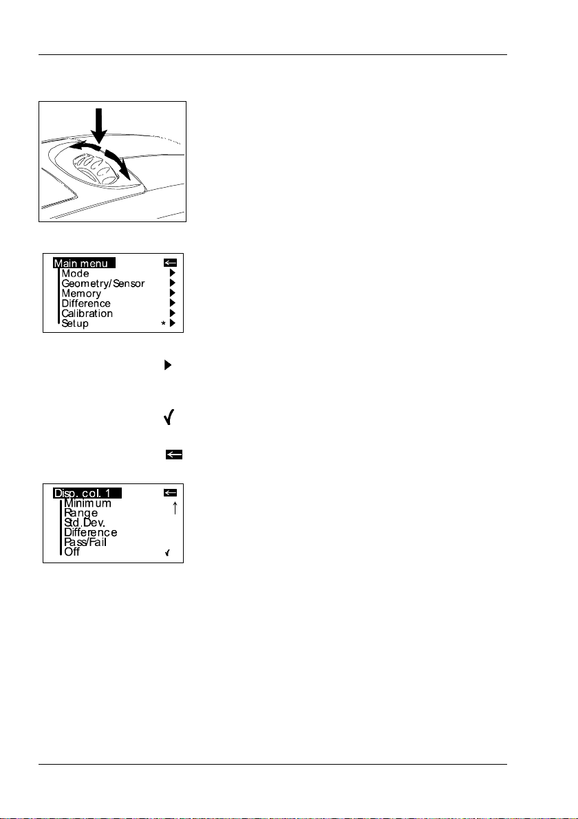
4.2 Nav iga tion
All control functions are controlled by the mode
scroll wheel. Pressing the wheel causes a menu to
appear in the display. Turning the wheel allows you
to move the black mark to the desired function and
to select or activate it by pressing the wheel.
What functions are displayed in the menu depends
on the settings in the main menu. The main menu is
the “central” level and can always be reached
quick ly.
Certain rules apply within the menus to make it
easier to navigate:
A black triangle to the right of a function indicates
that selecting this function will take you to a submenu.
A check mark on the right indicates that the function
in question has been activated.
Y ou can us e the arrow at the top right to switch the
display back by one level.
Arrows pointing up or down indicate that there are
other menu options above or below the part of the
menu that is visible. To reach these menu options,
simply turn the scroll wheel in the direction in which
the arrow is pointing.
Y ou can quickly switch back from the menus to the
measurement display by using the operate button.
In some cases this button also has another
function, but that will be indicated in the display (for
example Confirm -> operate).
14

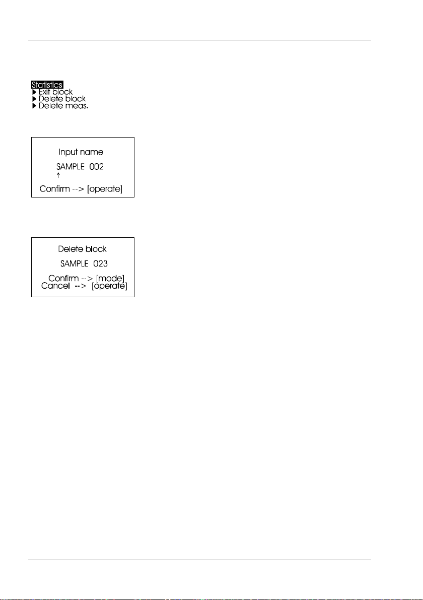
4.3 Change names/numbers
For some functions, you can enter or change the
date or name. The arrow pointing upward marks the
position that can be changed. T o change the
character, turn the scroll wheel. When you press the
wheel, the arrow jumps to the next character.
After you have adjusted the last character or
number, confirm your input by pressing the wheel.
When you enter the name, the arrow jumps to the
first character. This allows you to correct any
inadvertent incorrect entries. Y ou can confirm the
name in these menus at any time with the operate
key.
Getting started
15

Getting started
4.4 Overview o f mai n menu
Mode
Sample mode
Statistics
Continous
Basic mode
Advanced mode
Geometry/Sensor
Measurement without sta tistical evaluation.
Multiple measurement with statistics.
Continuous measuring with adjustable interval.
Measuring without statistics, s aving and difference.
Reactivates all menues and functions when Basic
mode was activated.
Select geometry and thickness sensor if applicable.
Memory
Memory
Select memory
Create memory
Delete memory
Display memory
Difference
Difference
Measure standard
Select standard
Create stan dard
Delete stan dard
Changestandard
Calibration
Setup
The following can be used together s imultaneously:
• Memory with: Sample mode, Statistics, Continuous
• Difference with: Sample mode, Statistics
Memory functions:
Turn saving on/off.
Select memory area from list.
Enter up to 50 memory areas.
Delete memory content or memory name.
Recall of memory content (use scroll wheel).
Settings for difference mode:
Turn difference measurement on/off.
Measure a stand ard.
Select s tan dard (if s aved).
Enter up to 50 standards and limits for Pass/Fail.
Delete individual stan dards .
Enter/change limit values for Pass/Fail.
Calibrate, change cal. values, GU - % scale.
Bluetooth®, Date/Time, Beeper, Display time, Language,
Info
16

5. Calibrate
5.1 Autodia gnosis
Calibrate
The holder with the integrated glass standard is
used for calibration. Always keep the measurement
unit in the holder. This protects the measurement
optics and ensures that the standard is always at
hand.
If you have several devices of this type, you must
put the unit in the holder which belongs to the unit
(see the ser ial number).
Make certain that the standard is clean and
there are no cracks on it.
When you place the device in the holder, make
certain that it ships firmly into place.
Whenever you turn on the device in the holder, it first
performs a self-tes t. During this tes t, any ch ang es in
the measurement signal are tested against saved
calibration data. This allows for a long-term calibration
so that a new calibration is required only about once a
week. Beyond that, calibration is only necessary if
there are significant weather changes (see under 6.2).
It is recommended that you perform the self-test in the
holder regularly (every day).
The autodiagnosis generally takes about 2 seconds.
“Please clean standard” or “Please test standard”
may be displayed. For more information on
cleaning, see Chapter 17.
A message will appear in the display informing you
that the autodiagnosis has been completed
successfully.
In some cases, the system may suggest that you
repeat the calibration. The reason for this may be
changed ambient conditions. It is also possible,
however, that the standard still has small amounts
of residue left over from cleaning. This problem can
generally be alleviated by cleaning with a dry optical
cleaning cloth.
17

Calibrate
5.2 Calibrate
5.2.1 Gloss
Y ou s hould recalibrate the device if ambient
conditions have changed. This applies espe cially
when changing location if major changes in
temperature and relative humidity may be expected
as a result (for example inside/outside).
When moving from cold areas to w arm areas, there
is a danger of condensation. For this reason, after
there has been a change in ambient conditions, you
should wait for an appropriate amount of time to
allow the optical components to adjust before
calibrating and using the unit.
Use the path shown on the left side to reach the
Calibrate menu option.
T o begin calibration, press the scroll wheel.
The calibration process is performed automatically
for all three geometries. The saved calibration values
of the standard appear in the display.
The unit then returns to the selection menu
Calibration.
Y ou can use the path s how n on the left side to
reach the Calibrate Thickness option.
5.2.2 Thickness (micro-TRI-gloss µ only)
Choose the sensor (Fe, NFe) first.
In the display appears the menu for the calibration.
Put the instrument on the metal standard, according
to sensor selection Fe or NFe, and press operate.
18

5.2.3 Change cal. values
Calibrate
After the zero setting has been performed, the
display AIR will appear. To proceed with this, hold
the instrument in midair and press the operate
button.
The successful calibration is confirmed in the
display (OK). The instrument returns to the
selection menu Calibration.
Note:
The film thickness measurement is also influenced
by the basis metal. It is therefore advisable to
perform the zero calibration on the uncoated metal
which is used for the object to be measured.
In this case place the instrument on your original
substrate instead of on the supplied metal plate.
The gloss values of the calibration standard in the
holder included w ith delivery are saved in the
measuring device. During automatic calibration, this
data is assigned to the standard in the holder.
In some cases it will be necessary to enter data for
a new calibration standard, for example if the
previous standard has be en damaged or scratched.
To ensure exact calibration, only original
standards from the manufacturer should be
used.
Y ou can use the path s how n on the right side to
reach the Chang e cal.values menu option.
At three angle units, a selection menu will appear
for geometries. Select the desired geometry and
press the scroll wheel.
19

Calibrate
A warning message appears. You can cancel this
process by pressing the operate button.
If you press the scroll wheel, you will continue with
the process of changing calibration values.
In the next display you can enter new calibration
values.
After you have entered the n ew value, a war ning
message appears again in the display. You can
again abort the process with operate.
If you confirm the new value by pressing the scroll
wheel, the value will be accepted.
After you have changed all necessa ry values, you
should recalibrate the measu rement device as
usual.
5.2.4 Status
20
This menu item provides you with information on the
calibration status of the unit.
In particular, you can check here whether the s aved
calibration values match those of the holder. The
display also indicates if an error message was
generated as a result of the last autodiagnosis or
calibration. If this has happ ened, further information
is available under Section Errors and w arning
messages.

5.2.5 Scale Gloss
5.2.6 Scale Thickness
Calibrate
Y ou can set the scales of the measurement values
for gloss and thickness separately.
Y ou can us e the Scale menu option to switch back
and forth between Gloss Units and Reflectance (see
the Section on Practical measuring suggestions).
Move the mark to the desired entry and press mode.
A check mark identifies the Scale that is selected.
After you switch the Scale, the unit must not be
recalibrated.
Y ou can us e the Scale menu option to switch back
and forth between µm and mil. Move the mark to the
desired entry and press mode. A check mark
identifies the Scale that is selected.
21

Calibrate
5.3 Calibrating standards
T o ens ure exact calibration, only original standards
from the manufacturer should be use d.
These are calibrated against tested primary
standards. Their surface must not be touched and
must be protected against scratches. Due to
environmental influences, however, the values of
standards can change over the course of time even
if they are handled gently. For this reason, you
should have the calibration standards tested by the
manufacturer at regular intervals (we recommend
annually).
5.4 Checking standard
We recommend the regular use of a separate test
standard for control of test equipment. The
frequency of this verification depen ds on the
conditions of usage (for example monthly). The
gloss standards are integrated into an aluminum
guide in which the measurement device is
positioned exactly. Perform the measurement as
you would normally, for example in Basic mode. The
displayed measurement value must not deviate from
the value printed on the standard by more than one
unit. Otherwise you should check whether there is
dirt and dust on the high gloss standard in the
holder or test standard. If cleaning and recalibration
do not offer any improvement, please get in touch
with our Customer Service.
22

Measur ement techniques
6. Measurement techniques
In accordance with the standa rd, the reflectometer
value is related to a black glass standard at a
defined index of refraction (generally 1.567) which is
thus equal to 100 units.
Reflectometers are differentiated by the angle of
incidence of the illuminating mechanism.
Geometries are set in the standards at 20°, 60° and
85°.
6.1 Paints and varnishes, plastics and similar materials
The various geometries are distinguished according
to their fields of application as follows:
Semi-gloss surfaces are measured at a n angle of
incidence of 60° and should fall within a range from
10 to 70 gloss units.
Highly reflective surfaces with measurement values
exceeding 70 units in the 60° geometry should be
measured at 20°.
On the other hand, matte surfaces with less than 10
gloss units (at 60°) should be measured at the 85°
geometry.
In addition, specific measuring geometries are
defined in some industries, e.g. ceramic and plastic
film applications recommend 45° geo metry or paper
and vinyl housing facades use 75° geometry .
23

Measur ement techniques
6.2 Anodized aluminum and other metal surfaces
The measuring unit is equipped with an extended
measuring range for measuring samples with a very
high reflectance.
The reflectance of non-metallic surfaces increases
with the angle of incidence. The reflective properties of
metals do not always behave in this manner. Because
of double reflection, the light is partially reflected on
the coating and partially on the metal underneath. For
a complete understanding of the reflective properties
of such s urfaces , it is recommende d to meas ure them
at all geometries.
In addition to the reference to a black glass standard
(gloss units), it is also common in the area of metals
to relate the reflectometer value to the amount of
irradiated light and to express it as a % (reflectance).
Y ou can select this in the Scale menu.
Notes
Proper measurements are only possible on level
surfaces.
Measurements on dirty, scratched or otherwise
distorted areas of the test specimen are not meaningful except as a way of determining the degree of such
imperfections by means of a gloss measurement.
Since it cannot be assumed that the gloss capacity is
not con stant over the entire s urface of the tes t
specimen, the reflectometer value can be measured
at several different places and the standard deviation
can be determined.
If the sample exhibits structures or directionally
dependent gloss properties, the structural features
and the direction of the incident light should be
specified for the measurement in the test report.
Samples that must be measured several times over
the course of an examination (for example weathering
samples) should be marked accordingly to ensure
that the measurement is made at the same point
during repeated tests.
24

6.3 Measurement of film thickness
The film thickness sensor functions according to the
magnetic method (Fe) or the eddy current method
(NFe). Therefore, the measurement results can be
distorted by strong magnetic fields or electromagnetic radiation.
The measurement of film thickness is influenced by
the thickness and magnetic (Fe) or electrical (NFe)
properties of the basis metal.
The measurement results can thus be distorted by
such factors as the composition or heat treatment of
the substrate. It is therefore advisable to perform the
zero calibration on the uncoated metal which is
used for the object to be measured.
Surface roughness also influences the measurement of the coating thickness. T o reduce random
errors, multiple measurements are recommende d.
If the paint film thickness is to be measured using a
magnetic substrate coated with a non-iron
metal (e.g. zinc plated steel sheet), the following
must be noted:
• For the NFe setting, the thickness of the
substrate, i.e. of the non-magnetic coating, must be
at least 50 µm.
• With the Fe setting, the thickness of the nonmagnetic coating is included in the measurement
result.
Measur ement techniques
25

Measur ement Modes
7. Measurement Modes
Y ou can select different types of measurement in
the Mode menu. The mode that is activated is
identified by a check mark.
7.1 Sample mo de
Single measurements can be performed without
statistical evaluation in Sample mode.
The results can be saved and compared with a
standard (refer to Memory or Difference).
When Memory is turned on, a name is suggested
after every measurement. Y ou can confirm this
name directly or change it.
26
If you would like to delete the last measurement,
press the scroll wheel and select the appropriate
menu item.

7.2 Statistics
Measur ement Modes
Y ou can make multiple measurements with each
sample in Statistics mode. These measurements
will be evaluated statistically and displayed.
The results can be saved and compared with a
standard. These functions must be p reviously
activated (refer to Memory or Difference).
When Memory is turned on, a name is suggested
after all measurements of a sample (block). You can
confirm this name directly or change it.
When the Statistics function is turned on, additional
functions are available depending on the context
after you press the scroll wheel.
27

Measur ement Modes
Note:
(micro-TRI-gloss µ only)
When STA TISTICS is activated, all film thickness
values are stored in the Memory independently of
the sonde used.
In the case of an incorrect substrate or a high film
thickness, “Infi“ is written to the memory.
When the instrument is switched off, the last setting
remains active.
7.2.1Number of measurements
Y ou can adjust the number of measurements per
sample or per block with this option, from 2 - 99.
28
Y ou can find this value in the measurement display
by looking for “n=” after the forward slash. The
number of measurements (which increases by one
each time a measurement is performed) appears
before the slash.

7.2.2Display
Measur ement Modes
In the Statistics measurement display, you can
assign the following data freely to three columns:
Value:
Last value to be measured
Mean value:
Arithmetic mean of the sample (block).
Maximum:
Highest measurement value of the sample
Minimum:
Lowest measurement value of the sample
Range:
The difference between the maximum and minimum
value.
Std. D e v.:
The sta ndard de viation of the s ample
Difference*:
The difference between the sample and a target
value.
Pass/Fail* :
Pass is displayed if the sample value falls within the
spe cified limits, o r Fa il if it falls o uts ide .
Off:
Turns off the display of the selected column.
* To be able to use these functions, a standard must
be measured, created or selected. In particular, a
limit value must be defined.
29
Measur ement Modes
7.2.3Exit block
8.2.4Delete block
This function terminates the block before it reaches
the required number of measurements n. It is useful
if you have selected a high number of
measurements for n, for example in the case of
large samples.
If Save is turned on, a display appears to enter a
block name for the sample.
This function deletes the current block.
8.2.5 Delete measurement
This function deletes the last measurement value.
30

7. 3Contin uous
Measur ement Modes
Y ou can use this function to perform up to 99
measurements atan adjustable measurement
interval. This is helpful when you are covering large
samples and you want to evaluate the homogeneity
of the surface.
Activate Continuous under M ode from the Main
menu.
A screen appears for starting a new sequence.
T o start the measurement, press operate. The unit
now performs measurements up to 99 times at the
set interval. Measurement values are show n in the
display after each measurement.
Y ou can interrupt the continuous measurement by
pressing the operate button (hold it down briefly).
The number of measurements, t he mean value, the
minimum and the maximum appear in the display.
The Pause symbol on the left side indicates that
you can continue the sequence, therefore press the
operate b utton.
T o end the sequence, press mode.
For starting a new sequence, press operate again
If saving is activated, a screen appears at start of a
new sequence, which allows to enter a sample
name.
31

Measur ement Modes
7.4 Basic mode
The measu ring interval can be cha nged before a
sequence is started. Therefore press the mode
wheel to open the Continuous submenu.
The longest measu rement interval possible is 9
seconds, the shortest 0 seconds for continous
measuring. The interval slightly increases wh en
thickness sensor is activated.
The selection options are limited to the most
essential in Basic mode. This also greatly simplifies
operation in this mode.
Y ou can select geometry and thickness sensor and
perform calibration. In addition, all functions in the
Setup menu item are available.
Basic mode is useful if you want to interrupt a
series of measurements and quickly perform some
other measurements in the middle without leaving
the series of measurements.
32
Once these other measurements are complete, you
can use
to return to the point where you interrupted the
series of measurements.

8 Geometry/Sensor
8.1 Geometry selection
Geometry/Sensor
In this menu, you can select the geometry for the
gloss measurement, just as the sensor for the film
thickness measurement (at micro-TRI-gloss µ).
Choose Gloss Geometry from the Geometry/Sensor
menu.
Y ou can choose between the representation of one,
two or all three geometries in the display.
The currently set angle combination is indicated in
the Geometry menu by a check mark.
Select the desired combination with the scroll wheel
and then confirm by pressing mode.
When Save is turned on, switching the geometry
automatically causes the program to switch to the
appropriate predefined area of memory.
8.2 Thickness Sensor selection
The currently selected sensor is indicated in the
display by a check mark.
Off
The film thickness sensor is switched off.
Fe
Magnetic base metal (iron or steel)
NFe
Non-iron metal (e .g. aluminium)
33

Geometry/Sensor
Combi
When changing the substrate, the sensor will be
switched over automatically
Choose the desired sensor with the scroll wheel.
Press mode to confirm the desired selection.
The selected sensor is indicated in the display.
Note:
The measurement unit can be selected in µm or mil
for display (see section Calibration: Scale
Thickne ss ).
8.3 Sensor-setting Combi
When switching the Thickness setting to Combi,
the measurement will be run through in the
sequence Fe - NFe.
As the measurement takes place on a
ferromagnetic substrate, the procedure w ill be
finished directly after the Fe measurement.
With the measurement on a non-magnetic substrate
the sequence will go through and therefore lasts
somew hat longer .
Note:
When STA TISTICS is activated, all film thickness
values are stored in the Memory independently of
the sonde used.
In the case of an incorrect substrate or a high film
thickness, „Infi“ is written to the memory.
When the instrument is switched off, the last setting
remains active
34

9. Memory
9.1 Memory
Memory
T o s ave measurement values, you must activate the
Memory function before measuring or else select or
create a memory. Up to 999 measurements can be
stored. A fixed memory area is already created for
each geometry or combination (e.g. M60°). These
memory areas cannot be deleted. A total of 50
memory areas can be created.
The Memory function can be used for sample mode,
Statistics and Continuous measurements. The
layout of the memory is such that the measurement
mode and the standard can be changed within a
memory area, but not the geometry.
Y ou can use this function to turn saving on or off. A
check mark indicates if the function has been
activated.
Turning on Memory automatically selects the area
in memory that is predefined for the currently set
geometry (for example M20°60°).
9.2 Select memory
When you press operate to start a reading, you are
asked to enter a name for this memory.
All available areas of memory are listed in this
menu, beginning with the one that is predefined.
The number of measurements saved for each area in
memory is shown on the right.
Select the appropriate memory area with the scroll
wheel and activate the selection by pressing mode.
This automatically turns on Save and switches the
geometry if necessary (if the selected memory area
is defined for other geometries than what was
previously set).
35

Memory
9.3 Create memory
9.4 Delete memory
Users can set up their own memory areas with this
function. Select the required geometry before you
activate this function. Then you must enter the
name of a memory area. You can confirm the
suggested name directly with the operate button or
change it with the scroll wheel. After you confirm,
Save is automatically turned on.
This menu lists all memory areas that have been
created with the number of values stored in each
one.
Use the scroll wheel to move the mark to the
memory area you would like to delete and press the
wheel.
A menu appears in which you can decide whether
you would like to delete just the content of the
memory area or the entire memory area.
9.5 Display memory
36
For pre-defined memory areas, you can only delete
the measurement values.
Y ou can transfer data that has been saved to a PC
via the interface. The values can also be show n in
the display at any time.
The “Display memory” function opens a menu in
which all memory areas that have been created are
listed. Select the desired area of memory with the
scr oll w h ee l.

Memory
The values of the first measurement appear in the
display. The sample name is displayed in the
highlighted field.
Turning the wheel switches the display to the next
sample with its corresponding values.
Which values are displayed in the columns (for
example mean value, min., max.) depends on the
display currently selected for Statistics.
37

Difference measurement and Pass/Fail
10. Difference measur emen t and Pass/Fail
Y ou can compare the readings of samples with the
value of a previously measured or saved standard.
For saved standards, you can also display whether
the test specimen falls within the limits (Pass) or
outside (Fail).
Up to 50 standards can be saved. They are stored in
a separate area of memory. For each geometry you
can determine:
- A target value
- Maximum and minimum for Pass/Fail,
see Create s tandard or Change s tandard.
10.1 Difference
Y ou can use this menu option to turn Difference
measurement on or off. A check mark indicates if
the function is active.
When you turn on Difference, the last standard to be
used is automatically selected.
If no standard is available, choose the function
“Measure standar d“ or “Create standard“ to
continue.
10.2 Measure standard
38
We recommend to perform several readings on the
standard with Statistics turned on.
Memory must be activated to store the measured
standard. Otherwise it will be temporary hold until
another standard is measured.
Activate “Measure standard” a nd p erform the
measurement with operate. With memory on, a
window appe ars after the last reading where you can
enter the standard’s name.
If you inadvertently select a name that has already
been used, a message will appear in the display
and the arrow will jump back to the first position of
the name.

10.3 Select standard
Difference measurement and Pass/Fail
The measured s tandard values are s aved as the
target values. At the same time, Difference
measurement is turned on and the measured
standard is activated. If you want to define limit
values additionally , you can use the “Change
stand ard” function.
For measuring the samples continue by pressing
operate. The display shows the sample values and
difference to the target.
The Measure stand ard function can also be reached
directly from the measurement screen by pressing
mode.
If you want to compare samples without saving the
standard, use the Difference mode with Memory
switched off. A measured standard will be kept
temporary then, until you measure another one.
T o s elect an existing standard, use the arrow to
move the mark to Select standard and then press
the whee l.
The first standard appears in the display. The t arget
value, minimum and maximum are displayed. For
values that are not defined, 0.0 or 2000 is displayed.
The name of the standar d appears inverted a t the
top rig ht.
Turning the scroll wheel causes the next standard to
be displayed.
When you have selected the desired standard in the
display, activate it by pressing on the wheel.
A reference to the selected data will appear in the
display.
T o sta rt Difference measurement pres s “operate“.
39

Difference measurement and Pass/Fail
10.4 Create standard
Standards can also be saved by entering the target
and limit values with the scroll wheel. Move the
mark to “Create standard” and activate the function.
A display appears in which you must assign a name
for the new standard. If you inadvertently select a
name that has already been used, a message will
appear to this effect and the marker arrow will jump
back to the first position of the name. Confirm the
name with the operate button.
In the next step you can define the target and limit
values of your standard.
Define standard
With the three angle device, a menu first appears in
which you can select the geometry.
40
After that, the menu appears for selecting the target
value, mini mum and maximum.
Select the desired variable and press on the scroll
wheel.
Now you can adjus t the corresponding value.
After the last number is activated, the display jumps
back to the previous menu.
In this manner you can enter additional target and/or
limit values for the standard one after the other if
need be. After the entries are complete, Difference
measurement is turned on with the new standard.

10.5 Change standard
10.6 Delete standard
Difference measurement and Pass/Fail
Y ou can use this function to change target values
and limit values of saved standards. You can also
use it to define limit values subsequently (for
example for a measured standard). Use the scroll
wheel to move the mark to Change standard and
press the wheel.
All standards are listed one after the other in the
following menu. Select the desired standard and
press the scroll wheel.
In the next step you can define the target and limit
values as described above.
Use the selection wheel to move the mark to Delete
standard in the Difference menu and then press the
wheel.
The Delete stand ard menu appea rs. All saved
standards are listed in this menu.
If there are more standards than can be shown in
the display, arrows on the right edge of the display
will point to additional standards.
Use the scroll wheel to move the mark to the
desired standard and press the wheel.
The standard to be deleted is listed again in the
display. Confirm by pressing the mode scroll wheel.
The unit then reverts to the previous menu.
41

Setup
11. Setup
11 .1 Bluetooth®
1 1 .2 Date/Time
Y ou can make general settings in the Setup menu,
for example Langu age or Display time.
Y ou can us e this menu option to turn the
Bluetooth® function on or off. Use the scroll wheel
to move the mark to Bluetooth® and press the
wheel.
When Bluetooth® is turned on, a check mark
appears at the end of the line. Additionally, the
Bluetooth® symbol appears shortly in the start
screen when you switch on the instrument.
The unit contains an integrated clock. This makes
the date and time of the measur ement available for
data transfer to a PC. The date and time are not lost
even when the battery is changed. If you would like
to change the time setting, use the scroll wheel to
move the mark to Date/Time and then press mode.
The display for setting the date and time appears.
1 1.3 Beeper
1 1.4 Display time
42
Y ou can use this menu option to turn the beeper on
or off. Use the scroll wheel to move the mark to
Beeper and press the wheel.
When the beeper is turned on, a check mark
appears at the end of the line.
T o s ave electricity , the unit automatically turns off
after a certain amount of time. Yo u can determine
this time yourself with Display time.

11.5 Language
11 .6 Info
Setup
You can use this menu to select the display
language.
Use the scroll wheel to move the mark to the
desired language and press the wheel.
Y ou can use this menu option to find the following
information:
• C atalog N o.
• Serial No.
• Ver sion numbe r of the firmware
• Date of the last calibration
• Date of the last certification
43

Interface
12. Interface
The measurement device is equipped with an
interface that allows direct communication with a
PC.
Measurement data can be transferred from memory
or directly after each measurement.
The easy-link program is included with delivery
for this purpose. The transferred data are displayed
immediately in a test report.
For data transfer you can use the USB cable
included with delivery or the wireless c onnection via
the integrated Bluetooth® module.
If no USB cable is attached, the instrument
transfers the da ta via Bluetooth® . Therefore,
activate the Bluetooth® function in the Setup menu
of the instrument.
44

12.1 Installation
Interface
Bluet ooth® :
Please refer to the separate Bluetooth® Installation
Guide.
Software easy-link and USB drivers:
Insert the easy-link CD into the CD drive and run the
„setup.exe“ for installation of the program. Follow
the instructions on the screen.
After installation, the default directory of the
appropriate Excel Reports will be “...\bykware\easylink“.
As you connect the device to the USB port of the
computer, it is recognized by the system and the
hardware assistant opens:
1. Choose “Install from a list“ and click the button
“Next“. Then select the folder “U SB Driver“ from the
easy-link CD. The driver setup begins. Note that if a
window displays a choice of buttons to “Continue
Anyway“ or “Stop Ins tallation“ click on “Continue
Anyway“. Click the “Finish“ button to complete the
installation of the 1st driver.
2. After short time the hardware assistant opens for
installation of the 2nd dr iver. Co ntinue the
installation as described above by following the
instructions.
After the setup is completed for both drivers, open
the gloss-link report from the easy-link folder.
45

Standards
13. Standards
ISO 2813 Paints and varnishes - Determination of specular
gloss of non-metallic paint films at 20°, 60° and 85°
ASTM D 523 Stan dard Test Method for Specular Gloss
ASTM D 2457 Standard T est Method for Specular Gloss of Plastic
Films an d Solid Pla stics
DIN 67530 Reflektometer als Hilfsmittel zur Glanzbeurteilung an
ebenen Ans trich- und Kuns tstoffobe rflächen
(Reflectometer as a means for gloss ass essment of
plane surfaces of paint coatings and plastics)
BS 3900 - D5 Methods of test for paints. Measurement of specular
gloss of non-metallic paint films at 20°, 60° and 85°
JIS Z 8741 Method of Measure ment for Specular Gloss iness
ISO 7668 Anodized aluminium and aluminium alloys -
Measurement of specu lar reflectance and specular
gloss at angles of 20°, 45°, 60° or 85°.
BS 6161 - 12 Methods of test for anodic oxidation coatings on
aluminium and its alloys. Measurement of specular
reflectance and specular gloss at angles
of 20°, 45°, 60° or 85°.
46

Standards
ISO 2178 Non-magnetic coatings on magnetic substrates -
Measurement of coating thickness - Magnetic
method
ISO 2360 Non-condu ctive coatings on no n-magnetic electrically
conductive basis materials. Measurement of coating
thickness. Amplitude-sensitive eddy-current method.
ASTM B 499 Measurement of Coating Thicknesses by the
Magnetic Method: Nonmagnetic Coatings on
Magnetic Basis Metals
ASTM D 1400 Measurement of Dry Film Thickness of Nonmetallic
Coatings of Paint, Varnish, Lacquer , and Related
Products applied on a Nonmagnetic Metal Base
T ap pi T 480 S pecular gloss of pa per and paper board at 75°
47

T echnical data
14. Techn ical data
General techn ical data
T emperature range +15 °C to +40 °C (60°F to 104°F) for operation
- 10 °C to +60 °C (-14°F to 140°F) for storage
Rel. humidity Up to 85% non-condens ing
Mearurement unit:
Memory 999 measurements with date and time, in up to 50
memory areas
Difference measurement Memory for 50 references
Interface USB
Evaluation software easy-link, included
Power sup ply 1 Mignon A lkaline (AA/LR6) or rechargeable NiMH
Battery 1.5VDC, max. 0.1A
Rechargeable 1.2VDC, max. 0.1A
External power supply USB, 5VDC, max. 0.1A
Dimensions (WxLxH) 48 x 155 x 73 mm
Weight 400 g
Gloss measurem ent:
Measurement geometry 2 0° 60° 8 5° 45° 75°
Measurement ar ea ( mm) 10 x 10 9 x 15 5 x 38 9 x 1 3 7 x 24
Measurement range 0-2000GU 0-1000GU 0-160GU 0 – 180GU
Co lor s e ns it ivity in spectral adjustment to CIE luminosity function
(2°) under illuminant CIE-C
Accuracy
Range Repeatability Reproducibility
0 - 100 GU 0.2 GU 0.5 GU
100 -2000 GU 0.2 % 0.5 %
S - type units:
0 - 10 GU 0.1 GU 0.2 GU
0 – 140GU
48

Film thickness measurement:
Substrate Fe: magnetic, e.g. iron
NFe: non magnetic, e.g. aluminium
Sonde One point
Measurement range 0....500 µm (0 … 20 mil)
Accuracy ±(1.5µm +2%*)
*of measured value
Min. substrate thickness Fe: 0.20 mm (8 mil)
NFe: 0.05 mm (2 mil)
Specifications subject to change without notice.
T echnical data
49

Errors and warning mess ages
15. Errors and warning messages
Memory full Trans fer the content of memory to a PC and then
delete the contents of memory.
Refere nce memory full A maximum of 50 references can be saved. It may
be necessary to delete old references.
Y ou will also find an error number for the following messages in the Calibration/
Sta tus menu to provide support for diagnostics:
T olerance Generally occurs only with major changes in
Error 01 climatic or weather conditions. The deviation was
success fullycompensated for by calibration and
correct measurements are still possible. You should
still recalibrate the device as soon as it is operating
in normal climatic conditions again. How ever if a
change in climate cannot be considered as the
cause of the problem, you should check whether the
standard is clean.
Pleas e call Service Autodiagnosis has dete rmined an impermissible
Service (invalid) deviation in the measurement signal
that cannot be remedied by recalibrating.
Error 02 Generally occurs when there is a significant amount
of dirt or dust on the standard or optics. First try to
clean the standard. You should only have the optics
cleaned by ou r Customer Service department, for
example as part of a yearly recertification.
Error 03 Defect in the electronics or operating error. First
check whether the standard is clean and whether
the device is properly snapped into the holder.
Error 04 Defect in the lamp or electronics.
Error 05 Defect in the electronics.
Infi Wrong basis metal, measurement range
exceeded or calibration error; recalibrate, if
necessary .
50

Errors and warning mess ages
Error Thickness Operating error: improper ap plication, raising
before measurement is complete, or calibration
error . Repeat the pr ocedure.
If the error is show n repeatedly despite
correct operation and calibration, please contact
our customer se rvice department.
Please observe the instructions on cleaning standards in the section on
Calibration.
Fluctuations in measurement values
Was the same point on
the sample used for all
measurements?
Yes. It may help to test
the calibration with an
additional sta ndard if
one is available.
Calibration correct:
Is the test surface
completely even and
does the measur ing
device have good
contact with the
sample?
Yes: Device defective
Do not attempt to make any repairs yourself! If a malfunction occurs on your
measuring device, our Customer Service department will be happy to help you
as quickly as possible.
No. Check how high the deviations are on
the sample itself.
Calibration not correct:
Recalibrate and clean the standard if
necessary .
No:
In this case, major deviations are possible.
Please contact our Cu stomer S ervice
department.
51

Cleaning a nd maintena nce
16. Cleaning and maintenance
• Do not insert any objects into the measurement
aperture for cleaning. The instrument could get
damaged - a ffecting a pro per and s afe operatio n.
• The instrument housing is resistant to a number
of solvents, but cannot be guaranteed to withstand
all chemicals. Y ou should therefore use a soft,
moist cloth for cleaning. For cleaning excessive dirt,
use ethanol or cleaning alcohol. Do not use any
acetone!
• Cleaning standa rds
The accuracy of the measurement can be
significantly impacted by using dirty or damaged
standards.
Since the surfaces of the standards are highly
sensitive, cleaning must be undertaken with great
care.
T o clean standards, use a new lint-free cloth, dust-
free lens paper or an optical cloth.
Apply only slight pressure as you clean and make
certain there are no large particles stuck in the cloth
that could damage the surface. Do not us e any
acetone!
For dirt that is difficult to remove, use an optical
cloth dipped in liquid. Then wipe the surface with a
dry optical cloth.
Exact calibration is not possible unless the
standard is in perfect condition. If the condition of
the standard seems doubtful
because of its appearance or measurement errors,
we will be happy to check it for you.
52

17. Service and Cer tification
Service
Besides the repair of your instrument we offer the
following ad ditional ser vices:
First diagnosis on the telephone or by e-mail
Call us or send us an e-mail and we will try to solve
your problem. If this is not successful, please send
us the instrument for repair.
Preventive main tenance, calibrati on, an d
recertification
For precautionary reaso ns we re commend regular
preventive maintenance. We carry out this preventive
maintenance automatically when you send us your
instrument for maintenance and rec ertification. We
clean the optics, check all functions, test and, if
required, adjust the measured values by using
reference standards . Y ou will receive a certificate,
which includes the retraceability to international
standards.
Loaners
During the period of repair we furnish you with a
loaner on req uest an d availability.
Maintenance agreement
In case you want to make sure that the necessary
maintenance is being done on a regular basis and
on time, we recommend a maintenance agreement.
Extended warranty contracts
Furthermore, you can request an extended w arranty
contract for additional 12 months.
Service and Certification
Order ing infor ma tion:
SP-4440 Calibration service
SE-4440 Extended warranty
53

Service and Certification
Service Centers for BYK-Gardner products
Germany
BYK-Gardner GmbH
Lausitzer Strasse 8
82538 Geretsried
Germany
Phone:+49-8171-3493-0
Fax: +49-8171-3493-166
USA
BYK-Gardner USA
9104 Guilford Road
Columbia, MD 21046
USA
Phone:+1-301-483-6500
Fax: +1-301-483-6555
China
BYK-Gardner Shanghai Office
Room 1407, SIP AI PLA ZA
103, Cao Bao R oad
Shanghai 200233
P .R. C hina
Phone: +86-21 -6475-8570
Fax: +86-21-6475-7284
54
Brazil
BYK-Gardner La tin America
Rua das Aroeiras, 771
Bairro Jardim-Santo André-SP
CEP 09090-000
Brazil
Phone:+55-11-2147-1 199
Fax: +55-11-2147-1168

Copyright
18. Copyright
This instruction manual is an important part of this instrument. It co ntains essential information about setting up, placi ng in service and use. If you pass
the device on to another user , ple ase ensure that the instruction manual is
included with the instrume nt. The manual must be studied careful ly before
working with the equipment. Please contact your regional service office if
you have any questions or require additional information about the device.
The technology and fittings are based on state-of-the art optic and
electronic techno log y . New devel opments and innovati ons are co nstantly
being integrated into the equipment. Thus, the diagrams, dimensions, and
technical data used in this manual may have changed as a result of adapting
the device to new infor mation and improvements.
© Copyright 2010 B YK -Gardner GmbH
All righ ts reserv ed
No portion of the software, documentation or other accompanying materials
may be translated, modified, reproduced, copied or otherwise duplicated
(with the exception of a backup copy), or distributed to a third party, without
prior written authoriz ation from B YK -Gardner GmbH . In any case, this
requires the prior writte n consent of B YK -Gardner.
BYK -Gardner GmbH of fers no guarantee that the software wi ll functio n
without error or that the functions incorporated therei n can be executed in all
applications and combinations selected by you.
No liability other than as provided by law is assumed for direct or indirect
damage sustained in associa tion with the use o f the instrum ent, the software
or documentation.
BYK -G ardner GmbH reser ves the right to update the sof tware and written
documentation without prior notice .
55

260 020 398 E 1008
 Loading...