

Page 1

Measure what you see.
Elektrohydraulische Tiefungsprüfmaschine
Cupping Tester
Betriebsanleitung Operating Instructions
Istruzioni d’uso
Instrukcja obsługi
A member of
Additives & Instruments
Page 2

D E I P
0803
215 014 802
Elektrohydraulische
Tiefungsprüfmaschine
Modell: Cupping Tester
Kat. Nr. PF-5400
Electrohydraulic
Cupping Tester
Cat. No. PF-5400
Apparecchio elettroidraulico
per prove di imbutitura
No di cat. PF-5400
Elektrohydrauliczny
tester do badania
tłoczności
Nr kat. PF-5400
Page 3

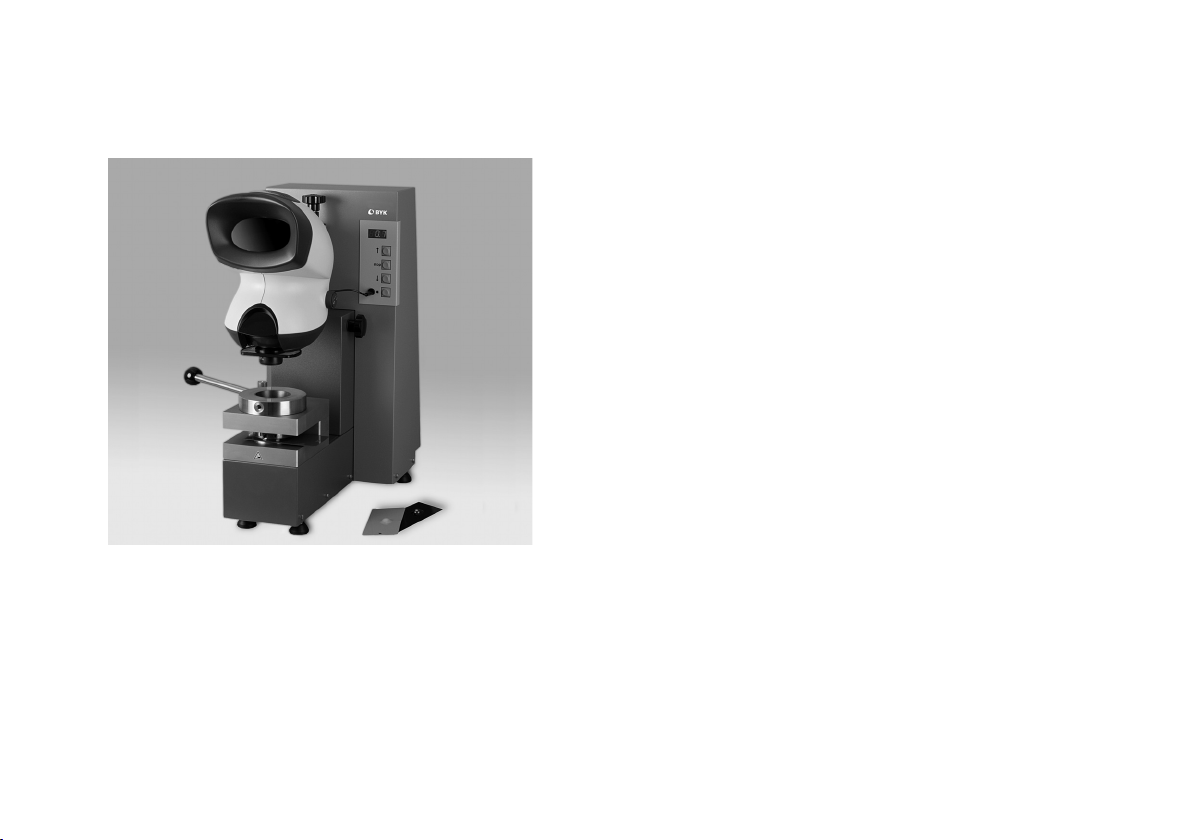
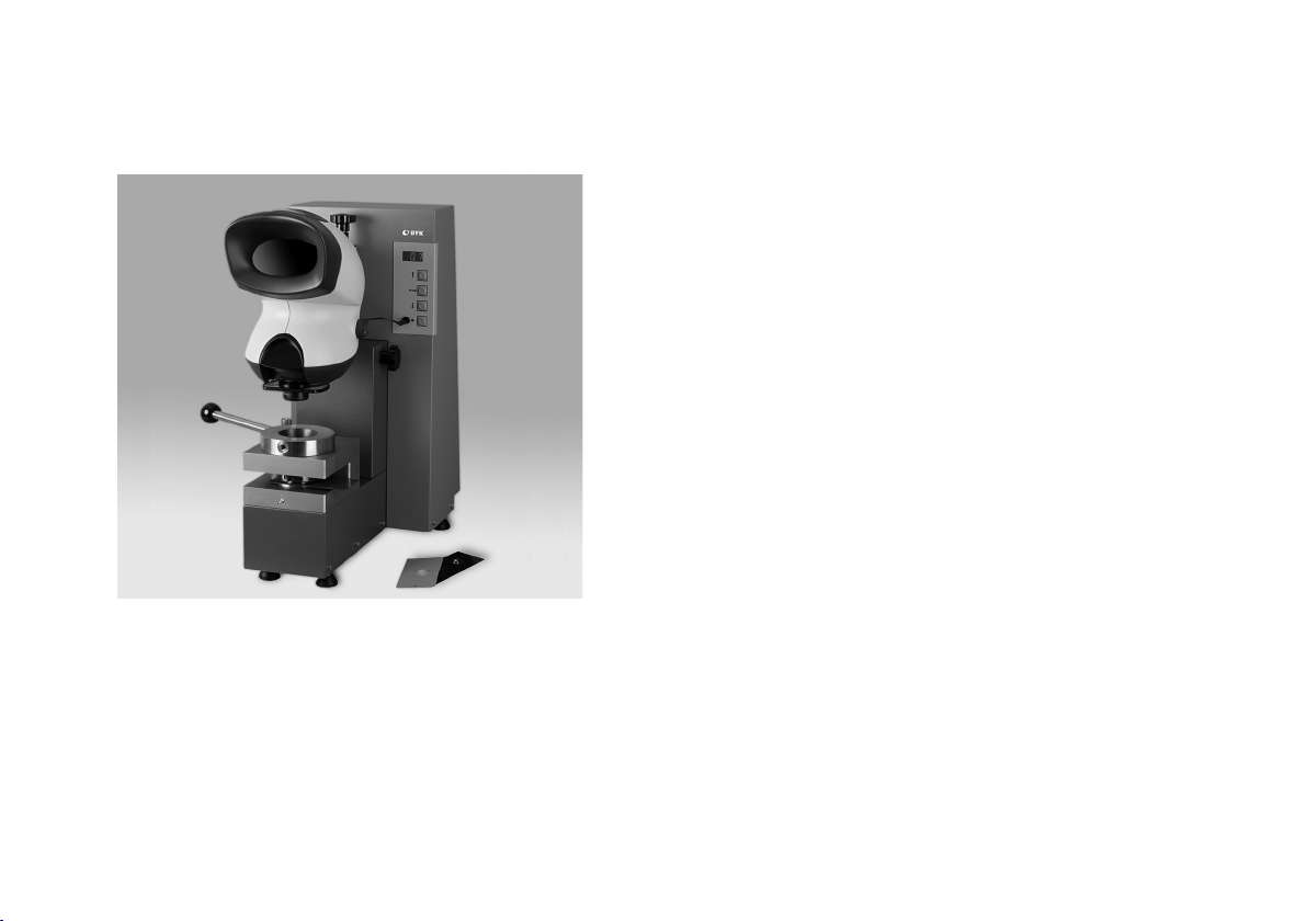
Abb. 1
Page 4

Elektrohydraulische
Tiefungsprüfmaschine
Inhaltsverzeichnis
1.0 Sicherheitshinweise
2.0 Vorbereitungen
2.1 Aufstellung
2.2 Elektrischer Anschluß
2.3 Probelauf
2.4 Stereomikroskop
3.0 Tiefungsprüfung
4.0 Digitalanzeige
5.0 Wartung
6.0 Fehlerprüfl iste
7.0 Lieferhinweise
8.0 Technische Daten
Technische Änderungen vorbehalten.
Page 5

1.0 Sicherheitshinweise
Vor dem Einschalten des Gerätes ist
sicherzustellen, daß die am Gerät eingestellte Betriebsspannung und die
Netzspannung übereinstimmen. Der
Netzstecker darf nur in eine Steckdose mit Schutzkontakt eingeführt
werden. Die Schutzwirkung darf nicht
durch eine Verlängerungsleitung ohne
Schutzleiter aufgehoben werden.
Warnung!
Jegliche Unterbrechung des Schutzleiters innerhalb oder außerhalb des
Gerätes oder Lösen des Schutzleiteranschlusses kann dazu führen, daß
das Gerät gefahrbringend wird.
Absichtliche Unterbrechung ist nicht
zulässig.
Achtung!
Hände und Finger nicht in den Zylinderdurchbruch zwischen Kugel- und
Exenterspannvorrichung bringen.
Bei sachgemäßem Gebrauch des Gerätes und dem Zubehör sind keine Gefahren zu befürchten, weder mechanischer
Art, noch durch elektrischen Strom.
Gewährleistung!
Es können keine Produkthaftungsund Gewährleistungsansprüche geltend gemacht werden, wenn das Gerät
nicht entsprechend den Hinweisen in
der Betriebsanleitung und am Gerät
betrieben wird.
Page 6

Probenplatten!
Achtung!
RS-232 Schnittstelle!
Zur Prüfung wird die Probenplatte in
die Exzenterspannvorrichtung gelegt
und fest eingespannt (max 40 Nm).
Achten Sie bei Verwendung der Prüfbleche auf scharfe Kanten. Es dürfen
keine anderen als die in den technischen Daten beschriebenen Prüfbleche verwendet werden.
Im Folgenden geben wir Ihnen Hinweise zum sicheren Gebrauch des
Gerätes.
Verwenden Sie bitte ausschließlich
das für das Gerät erhältliche Originalzubehör. Siehe hierzu Lieferumfang
und technische Daten.
Vermeiden Sie andauernde hohe Luftfeuchtigkeit und Kondenswasserbildung (siehe technische Daten) Schützen Sie das Gerät vor Spritz-wasser
und Chemikalien.
Führen Sie am Gerät weder mechanische noch elektrische Reparaturen
durch. Wenden Sie sich hierzu bitte
an unseren Technischen Kundendienst.
An der RS-232 Schnittstelle dürfen
nur Geräte angeschlossen werden,
die die Anforderungen für Sicherheitskleinspannung erfüllen. Die Nutzung
des 12 VDC-Ausgangs ist nur für das
Mikroskop zulässig.
Bitte beachten Sie, dass die auf dem
Typenschild angegebene Nennspannung des Gerätes mit der Nennspannung der Netzbuchse übereinstimmt.
Page 7
Netztrennung!
Ihr Gerät wird von der Versorgung
getrennt durch Abziehen des Stekkers der Netzanschlussleitung aus
der Netzsteckdose.
Achten Sie daher immer auf die freie
Zugänglichkeit des Steckers an der
Netzanschlussleitung. Auch sollte
sich die Netzsteckdose in der Nähe
des Gerätes befi nden.
Schutzausrüstung!
Beim Betrieb des Gerätes ist auf eine
ausreichende persönliche Schutzausrüstung zu achten.
Wir empfehlen hierzu Handschuhe,
Schutzbrille und eng anliegende
Kleidung.
Fehler und außergewöhnliche
Beanspruchungen
Wenn anzunehmen ist, daß ein gefahrloser Betrieb nicht mehr möglich
ist, so ist das Gerät außer Betrieb zu
setzen und gegen unabsichtlichen
Betrieb zu sichern. Es ist anzunehmen, daß ein gefahrloser Betrieb
nicht mehr möglich ist,
• wenn das Gerät sichtbare Beschä digungen aufweist
• wenn das Gerät nicht mehr
arbeitet
• nach längerer Lagerung unter
ungünstigen Verhältnissen
• nach schweren Transport-
beanspruchungen
Page 8
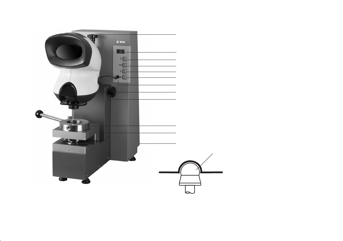
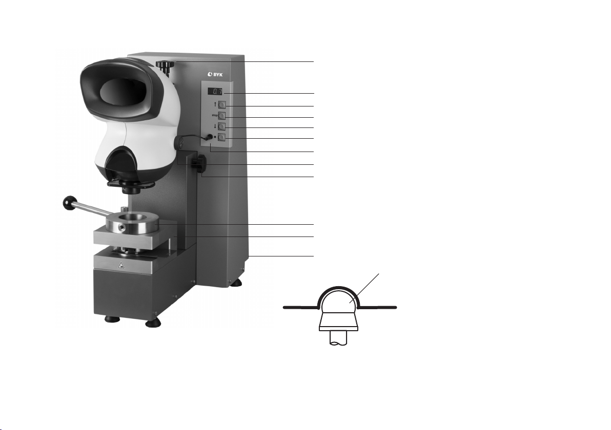
1 Feinstellschraube für die
2- / 4-fach Vergösserung
1
2
3
4
5
6
7
8
9
2 Digitalanzeige „Tiefung“
3 Taste START K
4 Taste STOP
5 Taste ZURÜCK L
6 Taste für Mikroskop beleuchtung
7 Buchse für Verbindungskabel
Mikroskop – Bedienfeld
8 LED Beleuchtung
Abb. 2
10
11
12
13
9 Arretierungsschraube für die
Positionierung des Mikroskops
10 Exzenterspannvorrichtung
11 Zylinderkopf
12 Netzschalter EIN / AUS
13 Stößel mit Kugelkopf
nach DIN EN ISO 1520
Page 9

2.0 Vorbereitungen
2.1 Aufstellung
Die elektrohydraulische Tiefungsprüfmaschine Modell 5400 wird
anschlußfertig und einschließlich
Ölfüllung geliefert.
Den Handgriff in eine der 3 Gewindebohrungen am Exzenter einschrauben.
2.2 Elektrischer Anschluß
Die Tiefungsprüfmaschine besitzt eine
automatische Netzspannungswahleinrichtung.
Netzkabel mit dem Gerät verbinden
und Netzstecker bei ausgeschaltetem
Gerät an Steckdose mit Schutzkontakt anschließen.
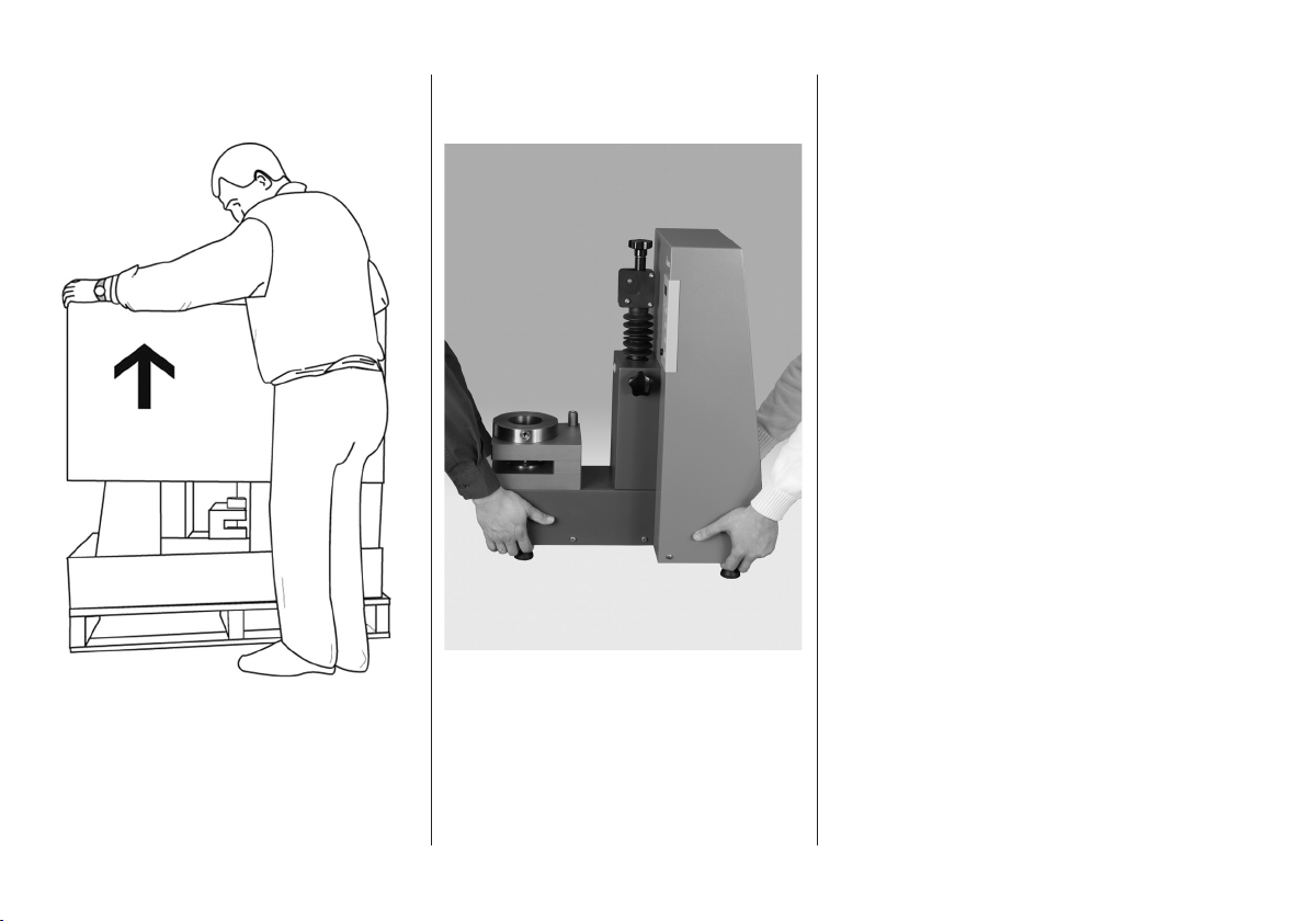
Verpackung entfernen
Transport mit 2 Personen
Page 10
2.3 Probelauf
Der erste Probelauf wird wie folgt
durchgeführt:
• Die Bedienelemente werden überprüft. Die Lage der Bedienelemente
ist in Abb. 2 dargestellt.
• Die Tiefungsprüfmaschine wird EIN
geschaltet (12).
Anzeige: 0.0 oder - - -
• Die Taste START K drücken und die
Endstellung (ca. 14 mm) ab warten.
• Den Stößel mit der Taste
ZURÜCK
L in die Nullposition
zurückfahren.
Anzeige: 0.0 oder - -
2.4 Stereomikroskop
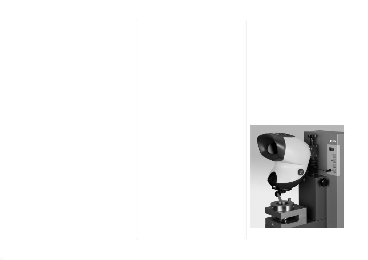
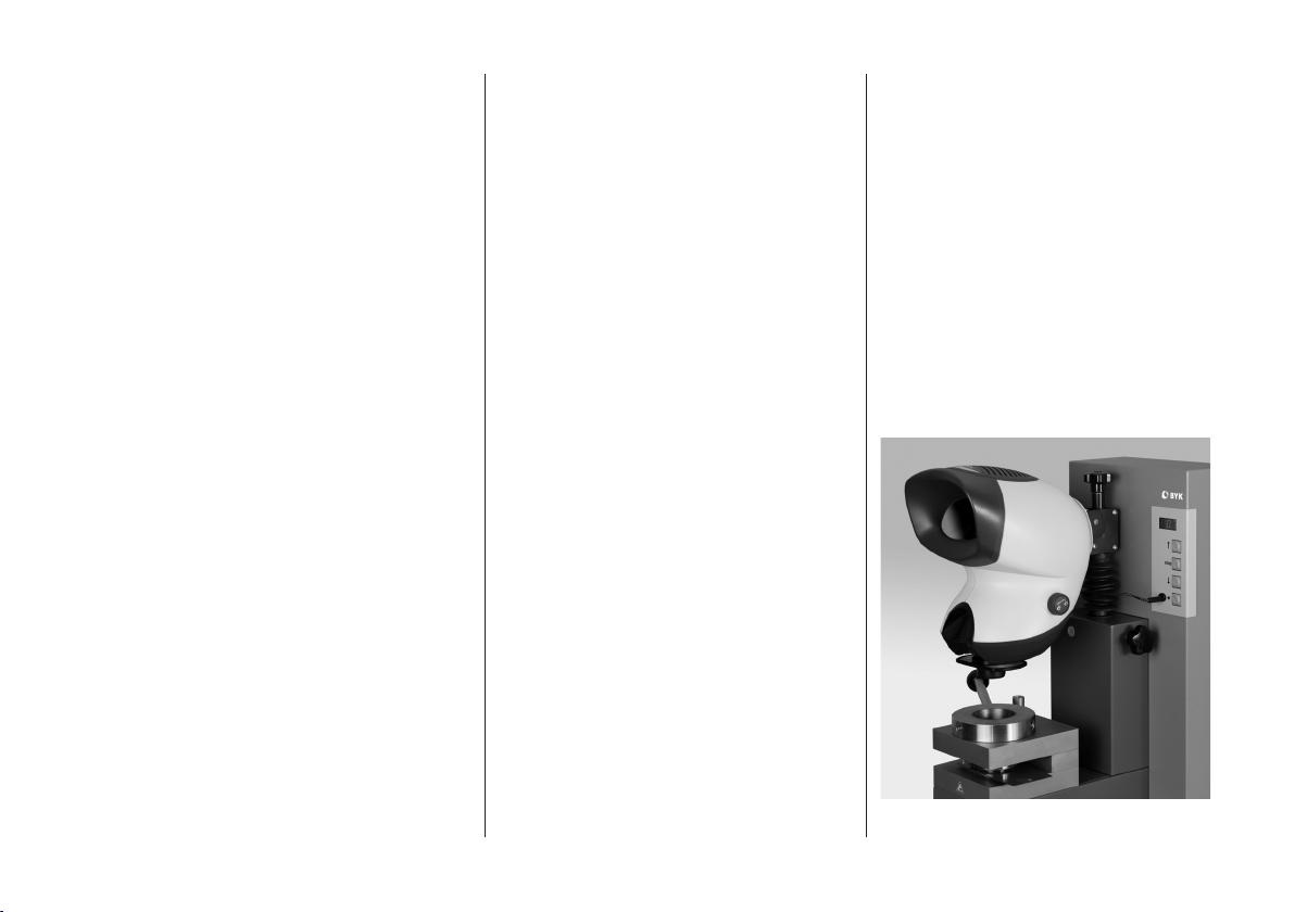
Das Stereomikroskop (Abb. 3) wird
wie folgt aufgehängt:
• Sicherungsschraube (Imbuss)
entfernen.
• Stereomikroskop einhängen und
mit Sicherungsschraube sichern.
• Die Linsen (2-fach und 4-fach) vorsichtig in Objektivhalter einschrauben (Feingewinde).
• Wird die 2-fach Linse verwendet,
muss das Mikroskop in der obersten Position stehen.
Wird die 4-fach Linse verwendet,
muss das Mikroskop nach unten
geschoben werden. Mit der Arretierungsschraube (9) wird die Position
des Mikroskops gesichert.
• Das Verbindungskabel zwischen
Mikroskop und Bedienfeld einstecken.
• Die Taste Mikroskopbeleuchtung ✵
betätigen.
• Die Kugel muß jetzt im Sichtfenster
scharf abgebildet sein.
• Die Bildschärfe des Mikroskops
wird mit der Feinstellschraube (1)
justiert.
• Den Netzschalter auf der Rückseite
des Gerätes EIN schalten.
Fig. 3 Stereomikroskop
Page 11
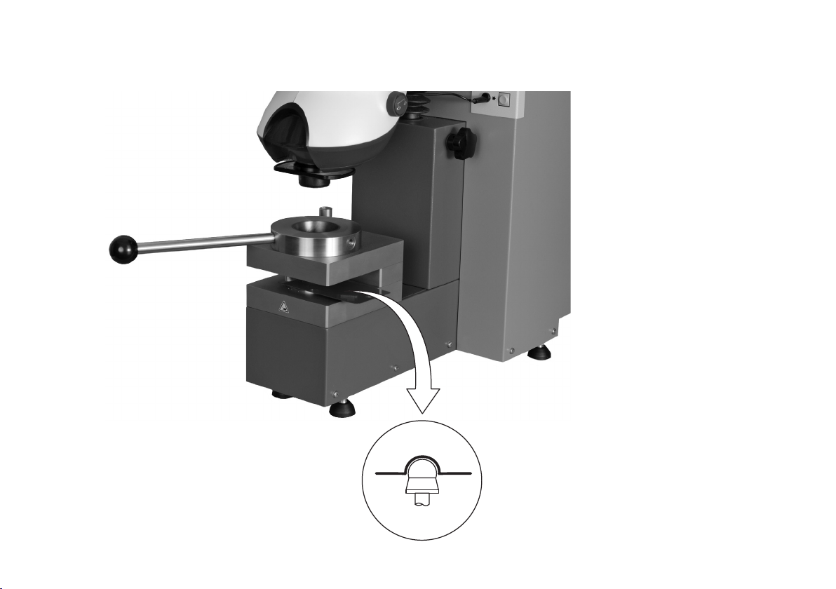
Abb. 4 Tiefung
Page 12

3.0 Tiefungsprüfung
Der Tiefungsvorgang wird wie folgt
durchgeführt:
• Prüfblech (max. 1 mm dick) in den
Zylinderdurchbruch schieben.
• Durch Drehen des Exzenters (10)
Prüfblech leicht einspannen.
• Taste START
Probe durch das Stereomikroskop
beobachten.
• Beim ersten erkennbaren Anriß
des Probenfi lms auf dem Prüfblech
die Taste STOP drücken und den
Tiefungswert an der Digitalanzeige
ablesen.
• Den Stößel mit der Taste L zurückfahren.
• Wenn die Nullposition erreicht ist,
die Exzenterspannvorrichtung lösen
und das Prüfblech entnehmen.
K drücken und die
Page 13

4.0 Digitalanzeige
5.0 Wartung
Die Digitalanzeige (2) benötigt keine
Aufwärm- und Stabilisierungszeit.
• Falls die Digitalanzeige nicht
0,00 ± 0,10 oder - - - anzeigt,
sollte der Technische Kundendienst
informiert werden.
• Zur automatischen Nullpunkteinstellung der Tiefungsprüfmaschine
ist ein Probelauf durchzuführen, wie
bereits unter 2.3 beschrieben.
Regelmäßiges Reinigen und Ölen der
Exzenterspannvorrichrung erhöht die
Funktionssicherheit.
Linsenreinigung
Objektive und Betrachtungslinse können mit staubfreiem Tuch (z.B. Brillenputztuch) gereinigt werden
Page 14

6.0 Fehlerprüfl iste
Symptom
Mikroskopleuchte
leuchtet nicht
Ursache
Lampe(n) defekt
(2 Stück)
Korrektur
Lampe wechseln
Symptom
keine Tastenfunktion
keine LED-Anzeige
Symptom
Schärfe nicht
einstellbar
Ursache
Sicherung
Ursache
Mikroskop ist nicht
in der richtigen Höhe
arretiert
Korrektur
Sicherung auf der Rückseite wechseln
Korrektur
Arretierungsschraube
(9) lösen, das Mikroskop
nach oben oder unten
verschieben und mit der
Feststellschraube (1) die
Schärfe fein justieren,
Arretierungsschraube
wieder festdrehen.
Page 15

7.0 Lieferhinweise
Tiefungsprüfmaschine
Zum Lieferumfang gehört folgende
Grundausrüstung:
• Kat.Nr. PF-5400
Tiefungsprüfmaschine mit offenem
Zylinderkopf einschließlich
Anschlußkabel und Stecker,
Aufnahme für Mikroskophalter und
Digitalanzeige
• Werkzeugsatz bestehend aus
1 Steckschlüssel
• Normalprüfwerkzeug (bereits in der
Maschine eingebaut) nach
DIN EN ISO 1520, bestehend aus:
Stößel mit Kugel 20 mm ø
Matrize 27 mm ø
Niederhalterring
• Bedienungsanleitung
Das Stereomikroskop muss separat
bestellt werden:
• Bestell-Nr. PF-5411
Stereomikroskop mit Einsätzen
für 2- und 4-fache Vergrößerung
mit Mikroskophalter und LED
Beleuchtung
Page 16

8.0 Technische Daten
Spannung: 115 V - 230 V
60 / 50 Hz
Automatische Umschaltung !
Leistungsaufnahme: 700 VA
Sicherungen: T 1,6 A : 250 V
(230V Netzspannung)
T 3,15 A : 250 V
(115V Netzspannung)
DC-Ausgang: Mikroskopbeleuchtung
5,1 VDC, 660 mAh
Betriebstemperatur: +10°C bis + 40°C
Lagertemperatur: 0°C bis + 50°C
Luftfeuchtigtk.: < 85% relative
Luftfeuchte, nicht
kondensierend/ 35 °C
Tiefungsprüfmaschine
Maße: H x B x T
650 x 280 x 600 mm
Gewicht: 55 kg
Stereomikroskop (optional)
Maße: H x B x T
300 x 280 x 400 mm
Gewicht: 4 kg
Andruckvorrichtung: Excenter mit 280 mm
Hebelarm.
Spannkraft max.
40 Nm
Hydraulik: Geschlossenes
System mit
Überlastabschaltung!
Öldruck max. 30 bar
Probenplatten: nach
DIN EN ISO 1520
aus Stahl, Aluminium
oder Kunststoff,
nicht größer als
200 x 600 x 1 mm
Linse: 2 Stück,
(2-fach / 4-fach)
Tiefungsgeschwindigkeit:
0,2 mm/s
Page 17

Page 18
D E I P
0803
215 014 802
Electrohydraulic
Cupping Tester
Cat. No. PF-5400
Page 19

Fig. 1
Page 20

Electrohydraulic
Cupping Tester
Table of Contents
1.0 Safety Information
2.0 Preparations
2.1 Set-up
2.2 Electrical Connection
2.3 Test Run
2.4 Stereo Microscope
3.0 Cupping Test
4.0 Digital Display
5.0 Maintentance
6.0 Trouble Shooting
7.0 Ordering Guide
8.0 Technical Data
Technical Data are Subject to Alterations.
Page 21

1.0 Safety Information
Before switching on the unit, please
make sure tthat the nominal voltage
given in the label on the instrument
corresponds to the nominal voltage
of the mains socket. The unit must
be plugged into a faultless grounded
outlet.
Warning!
Any break in the ground conductor
either inside or outside the unit, or
any loosening of the ground
connection, may make the unit
hazardous to operate. Never break
the ground connection intentionally!
Attention!
For USA use only: Detachable Power
Supply Cord – Listed, type SVT or
SJT, 18 AWG. Terminates in parallel
blade grounding type plug 125 V,
15 A confi guration.
Attention!
Don't put the hands and the fi ngers in
the cylinder opening between the ball
and the eccentric clamping ring. In
case the instrument and its accessories
are used properly there is no risk of
danger, neither of mechanical nature
nor by electric current.
Warranty!
The instrument shall not be subject to
any claims for warranty of quality or
for general liability in case the
instrument was operated not
according to the instructions given in
the operation manual and on the
instrument.
Page 22
Sample!
Attention!
RS-232 interface!
For testing purposes insert the sample
into the eccentric clamping ring and fi x
it tightly (max. 40 Nm).
In case you use test panels beware of
sharp edges. Only the test panels as
described in the technical data shall
be used.
In the following please fi nd the
instructions for the safe use of the
instrument.
Please use only the original
accessories for the instrument. Please
refer to the ordering guide and the
technical data.
Please do not expose the instrument
for a long time to highly humid
environment and avoid the forming of
condense water (see technical data).
Save the instrument from water
splashes and chemicals.
Do not carry out any mechanical or
electrical repair work at the instrument
yourself. In case of need please
contact our technical service.
Only instruments shall be connected
to the RS-232 interface which comply
with the requirements for safety extra
low voltage. The 5.1 VDC exit
provides the connection for the
microscope only.
Page 23
Power disconnected!
Safety gloves!
Defects and Extreme Usage
The instrument is disconnected from
the power source by pulling the plug
of the power supply cable out of the
mains socket. For this reason the
power supply shall always be free for
access. Also the mains socket should
be near the instrument.
Caution double pole/neutral fusing,
disconnect plug of power cord from
socket before service.
Caution: For continued protection
against risk of fi re replace only with
same type and rating of fuse.
During operation of the instrument the
operator shall be protected properly.
We recommend safety gloves, safety
glasses and tightly fi tting clothing.
If safe operation can no longer be
presumed, shut down the unit and
secure it against unintended
operation. The unit must be presumed
unsafe to operate:
• if it shows visible damage
• if it no longer operates
• if it has been stored for long
periods under adverse conditions
• after harsh treatment during
shipping
Page 24
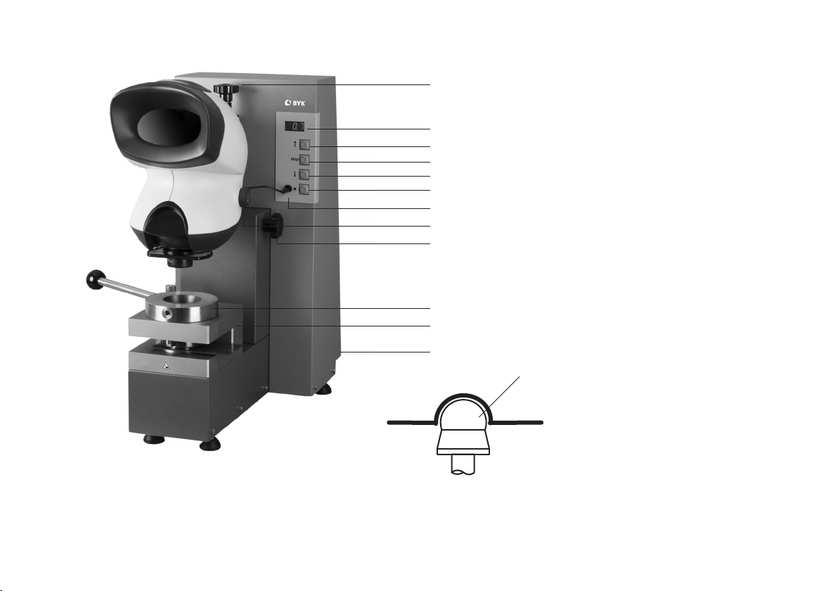
1 Adjusting wheel for magnifi cation
(2- and 4-fold)
1
2 Digital Display "Cupping"
Fig. 2
10
11
12
2
3
4
5
6
7
8
9
13
3 START Button K
4 STOP Button
5 REVERSE Button L
6 Switch for Microscope Lamp
7 Socket for the microscope – control
panel connection cable
8 Illumination Adjustment Control
for Microscope Lamp
9 Knurled locking wheel for
positioning the microscope
10 Eccentric Clamping Ring
11 Cylinder Head
12 Power Switch
ON / OFF (EIN / AUS)
13 Indenter and ball in accordance with
DIN EN ISO 1520
Page 25
2.0 Preparations
2.1 Set-up
The electrohydraulic cupping tester,
model 5400, is shipped ready for
connection and including the basic
oil fi ll.
Screw the handle in one of the 3
inside threads of the eccentric
clamping ring.
2.2 Connection to the
Mains Supply
The electrohydraulic cupping tester
has an automatic power supply
detection. Connect the power cord to
the machine and plug the power plug
into a shockproof socket.
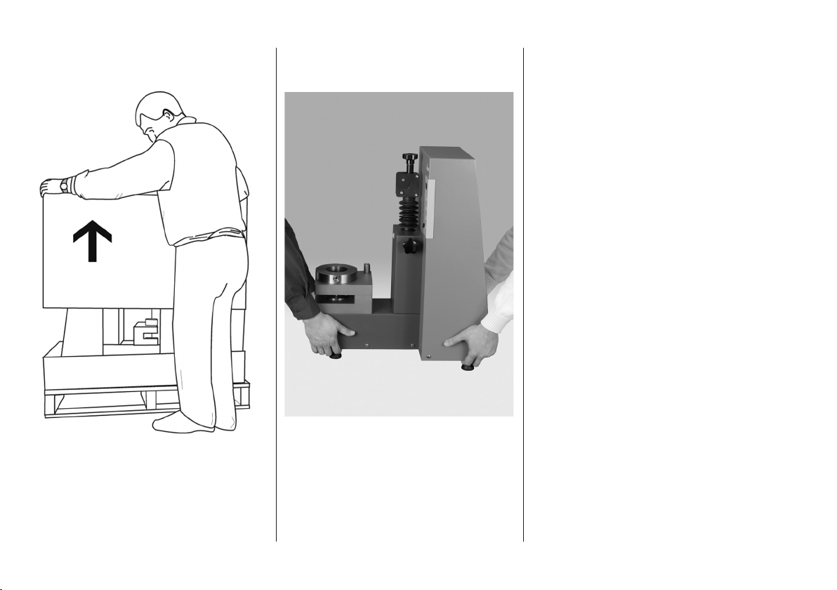
Remove the packing
Transport with 2 persons
Page 26
2.3 Test Run
• Switch the Cupping Tester ON
(= EIN / 12).
Display: 0.0 or - - -
• Press the START button
K and wait
until the indenter reaches the fi nal
position (approx. 14 mm).
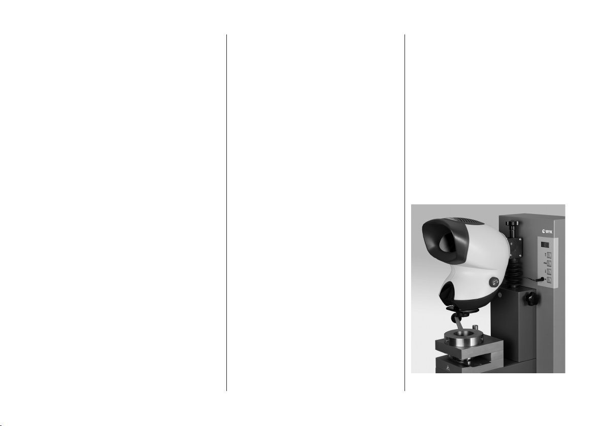
2.4 Stereo Microscope
To mount the stereo microscope
(Fig. 3) proceed as follows:
• Remove the safety screw.
• Hook in the stereo microscope
and tighten the safety screw.
• Press the button (6) for switching
on the lamp of the microscope.
• The ball should now be clearly
visible on the monitor.
• Turn the adjusting wheel (1) to
adjust the focus of the microscope.
• Press the REVERSE button
L to
move the indenter back to the initial
position.
Display: 0.0 or - - -
• Carefully screw the objectives
(2fold or 4fold) onto the lens mount
(fi nepitch thread).
• If using the 2-fold lens, the microscope needs to be fi xed at the upper setting. If using the 4-fold lens,
the microscope needs to be moved
downwards to the lower setting.
Release the knurled locking wheel
(9) to move the microscope up or
down. Tighten the knurled locking
wheel (9) to fi x the microscope in
the nedded position.
• Connect the microscope to the
control panel with the connection
cable.
• Switch ON (=EIN) the power
switch on the rear panel of the unit.
Fig. 3 Stereo Microscope
Page 27
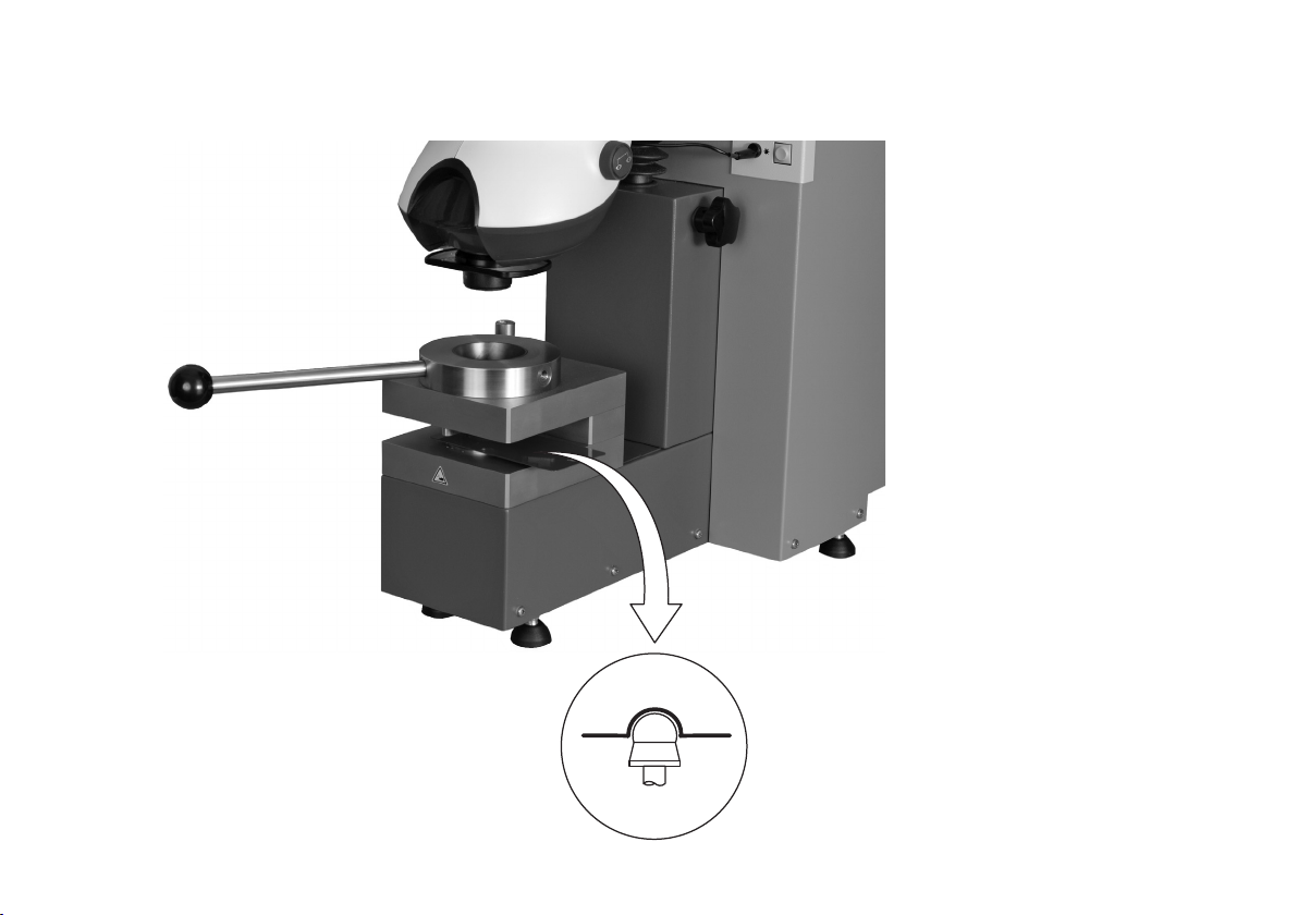
Fig. 4 Cupping Test
Page 28

3.0 Cupping Test
Carry out the cupping test as follows:
• Insert a test panel (max. thickness
1 mm) into the the cylinder opening.
• Turn the eccentric clamping ring
(10) to slightly clamp the test panel.
• Press the START button
closely watch the sample through
the stereo microscope.
• With the fi rst visible crack of the
paint fi lm on the test panel press the
STOP button and read the cupping
value from the digital display.
• Press the REVERSE button
move back the indenter.
• After the indenter reaches the initial
position, loosen the eccentric
fastening device and take out the
test panel.
K and
L to
Page 29

4.0 Digital Display
5.0 Maintenance
The digital display (10) does not
require any warm-up or stabilization
time.
• If the displayed does not read
0.00 by ± 0.10 or - - - , please call
our Service Department for
maintenance or repair instructions.
• Check the automatic zero setting of
the Cupping Tester by performing a
test run as described in chapter 2.3.
The function safety will be raised, if
the eccentric clamping ring will be
cleaned and will be oiled occasionally.
Lens cleaning
The objectives and viewing lens
should be cleaned with a dust free
cloth (e.g. for cleaning glasses).
Page 30

6.0 Trouble Shooting
Symptom
Mikroskope lamp is
not lit
Cause
Microscope
cable not
connected
Remedy
connect
(refer to 2.4)
Symptom
No switch functions
No LED display
Symptom
No focus possible
Cause
Fuse
Cause
Microscope is not
on the right track
elevation
Remedy
Replace fuse at rear of
instrument
Remedy
Untighten the wheel (9)
to move the microscope in the right position.
Final adjustment with
wheel (1)
Page 31

7.0 Ordering Guide
Cupping Tester
The delivery includes the following
basic equipment:
• Cat.No. PF-5400
Cupping Tester with open cylinder
head including connection cable
and plug, adapter for microscope
holder, and digital display
• Set of tools including
1 Socket wrench
• Built-in standard test tool in
accordance with DIN EN ISO 1520,
consisting of:
Indenter and ball: 20 mm ø
Die: 27 mm ø
Retaining Ring
• Operating instructions
Extra features, available on special
order:
• Cat.No. PF-5410
Stereo microscope with insertions
for 2- and 4fold magnifi cation,
incl. microscope holder and LED
illumination
Page 32

8.0 Technical Data
Voltage: 115 V - 230 V
60 / 50 Hz
Automatically switch !
Power Supply: 700 VA
Microscope (optional)
Dimensions: H x W x D
300 x 280 x 400 mm
(11,8 x 11 x 15,7 in)
Weight: 4 kg (8,8 lbs)
Fuse: T 1,6 A : 250 V
(230 voltage)
T 3,15 A : 250 V
(115 Voltage)
DC-Voltage: Microscope lamps
5,1 VDC, 660 mAh
Operation
Temperature: + 10 °C - + 40 °C
Stock
Temperature: 0 °C - + 50 °C
Humidity: < 85 % relative
humid, not
condensed/ 35 °C
Cuppingtester
Dimensions: H x W x D
650 x 280 x 600 mm
(25.6 x 11 x 23.6 in)
Weight: 55 kg (121 lbs)
Clampingring: Eccentric clamping ring with 280mm
lever arm.
Power max. 40 Nm
Hydraulic: Closed system with
safety device!
Oil pressure
max. 30 bar
Test panel: agree with
DIN EN ISO 1520
from steel, aluminium
or plastic,
max. dimensions
200 x 600 x 1mm
(7,9 x 24 x 0,04in)
Lens: 2 pieces (2-time and
4-time magnifi cation)
Speed: 0.2 mm/s
Page 33

Page 34
D E I P
0803
215 014 802
Apparecchio
elettroidraulico
per prove di imbutitura
No di cat. PF-5400
Page 35
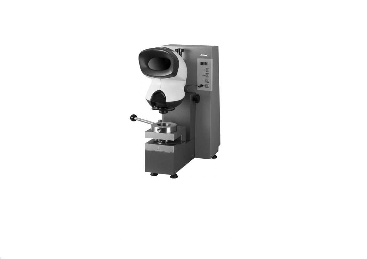
Fig. 1
Page 36

Apparecchio elettroidraulico
per prove di imbutitura
Indice
1.0 Informazioni sulla sicurezza
2.0 Preparativi
2.1 Impostazioni
2.2 Collegamenti elettrici
2.3 Collaudo
2.4 Stereomicroscopio
3.0 Prova di imbutitura
4.0 Display digitale
5.0 Manutenzione
6.0 Risoluzione dei problemi
7.0 Guida agli ordini
8.0 Dati tecnici
I dati tecnici possono subire variazioni.
Page 37

1.0 Informazioni sulla
sicurezza
Prima di accendere l’apparecchio,
assicurarsi che la regolazione del
voltaggio sull’apparecchio corrisponda
al voltaggio della presa di corrente.
L’apparecchio deve essere collegato
a una presa con messa a terra.
Avvertenza!
Eventuali allentamenti o interruzioni
del fi lo di terra all’interno o all’esterno
dell’apparecchio possono renderne
pericoloso l’utilizzo. Non interrompere
mai la connessione del fi lo di terra
intenzionalmente.
Attenzione!
Solo per gli USA: cavo di alimentazione
separabile – in elenco, tipo SVT o SJT,
18 AWG. Confi gurazione del terminale:
spina con messa a terra a lamine parallele, tipo 125 V, 15 A.
Attenzione!
Non mettere le mani e le dita
nell'apertura cilindrica tra la sfera e il
tenditore eccentrico. Nel caso in cui lo
strumento e gli accessori siano usati
in modo appropriato non c'è rischio di
pericolo, nè di natura meccanica nè
elettrica.
Avvertenza!
Lo strumento non sarà soggetto a garanzia per la qualità o per la responsabilità generale del fornitore nel caso in cui
lo stumento non sia stato maneggiato
secondo le istruzioni date nel manuale
operativo o indicate sullo strumento.
Page 38
Campione!
Attenzione!
Interfaccia RS-232
Per le prove inserire il campione nel
tenditore eccentrico e fi ssarlo stretto
(max. 40 Nm).
In caso di uso di pannelli, attenzione
ai bordi taglienti. Dovranno essere
usati solo i pannelli come descritti nei
dati tecnici.
Seguono le instruzioni per un uso
sicuro dello strumento.
Usare solo accessori originali dello
strumento. Fare riferimento alle informazioni per l'ordine e ai dati tecmoco.
Non esporre lo strumento per lungo
tempo in ambienti molto umidi e evitare la formazione di condensa (V. dati
tecnici). Mettere lo strumento al riparo
da spruzzi di acqua e prodotti chimici.
Non effettuare nessun lavaro di riparazione elettrico o meccanico. In caso
di necessità per favor contattare il
servizio di assistenza.
Solo gli strumenti devono essere
collegati all'interfaccia RS-232 che
concorda con i requisti di sicurezza
per le basse tensioni. L'uscita 5.1
VDG offre la connessione solo per
il microscopio.
Page 39
Disconnessione dalla rete!
Lo strumento è disconnesso
dall'alimentazione tirando la spina del
cavo di alimentazione dalla presa. Per
questa ragione l'alimentazione deve
essere sempre libera per accedervi.
Inoltre, le preso devono essere vicine
allo strumento.
Attenzione: disconnettere il cavo di
alimentazione dalla rete prima del
service.
Attenzione: per la protezione contro
il rischio di fi amme, sostituire i fusibili
solo con lo stesso tipo e portata.
Guanti di protezione!
Durante le operazioni con lo strumento l'operatore deve essere protetto
in modo appropriato. Si raccomando
l'uso di guanti di protezione, occhiali
di protezione e abiti con vestibilità
attillata.
Guasti e condizioni sfavorevoli
all’utilizzo
Se c’è motivo di dubitare della sicurezza dell’apparecchio, disattivarlo e
assicurarsi che non possa
essere messo in funzione
inavvertitamente. Si deve dubitare
della sicurezza dell’apparecchio nei
seguenti casi:
• se presenta danni visibili
• se non funziona più
• se è stato conservato per lunghi
periodi in condizioni inadeguate
• se ha subito brusche sollecitazioni
durante il trasporto
Page 40
1 Vite di arresto per ingrandimento
2 x / 4 x
1
2
3
4
5
6
7
8
9
2 Visualizzazione digitale
"imbutitura"
3 Tasto START K
4 Tasto STOP
5 Tasto REVERSE L
6 Interruttore lampada microscopio
7 Presa per il microscopio –
pannello di controllo cavo di
connessione
Fig. 2
10
11
12
13
8 Regolatore della luminosità
della lampada del microscopio
9 Vite di arresto
10 Tenditore eccentrico
11 Testata del cilindro
12 Interruttore di alimentazione
ON/OFF (EIN / AUS)
13 Punzone con testa sferica, a norma
DIN EN ISO 1520
Page 41
2.0 Preparativi
2.1 Impostazioni
L’apparecchio elettroidraulico per
prove di imbutitura, modello 5400,
viene fornito pronto per la connessione
e con la riserva d’olio di base.
Avvitare la maniglia in uno dei tre
fi letti interni del tenditore eccentrico.
2.2 Collegamenti elettrici
L'imbutitore elettroidraulico ha
un rilevamento automatico
dell'alimentazione. Collegare il cavo di
alimentazione alla macchina e inserire
la spina in una presa elettrica.
Togliere l'imballo
Trasportare con 2 persone
Page 42
2.3 Collaudo
2.4 Stereomicroscopio
• Selezionare la lente 2x.
• Accendere l’apparecchio (=EIN/12);
Display: 0.0 o - - -
• Premere il tasto START
K e
aspettare fi nchè il punzone
raggiunga la posizione fi nale
(circa 14 mm)
• Premere il tasto REVERSE
L per
riportare il punzone indietro nella
sua posizione iniziale;
Display: 0.0 o - - -
• Spegnere l’apparecchio (=AUS/12)
Per il montaggio dello stereomicroscopio (Fig. 3) procedere nel modo
seguente:
• Svitare la vite di arresto, estrarre
il distanziatore e montare il microscopio. Attenzione: il perno di
ritenzione deve incastrarsi nel
distanziatore nero.
• Inserire la rondella e serrare completamente la vite di arresto.
• Avvitare con cura le due lenti (2x e
4x) nel portalenti (fi lettatura fi ne).
• Connettere il microscopio; verifi care
il cavo di connessione del pannello
di controllo.
• Accendere con ON (=EIN/1)
posto sul pannello posteriore
dell'apparecchio.
• Premere il pulsante della lampada
del microscopio ✵ per accendere la
lampada.
• A questo punto sul monitor dovrebbe
essere chiaramente visibile la sfera.
• Se necessario, mettere a fuoco
utilizzando l’apposita manopola oppure spostando l’intero microscopio
verso l’alto o verso il basso. A questo
scopo svitare la vite esagonale
(sotto il coperchio bianco).
Fig. 3 Stereomicroscopio
Page 43
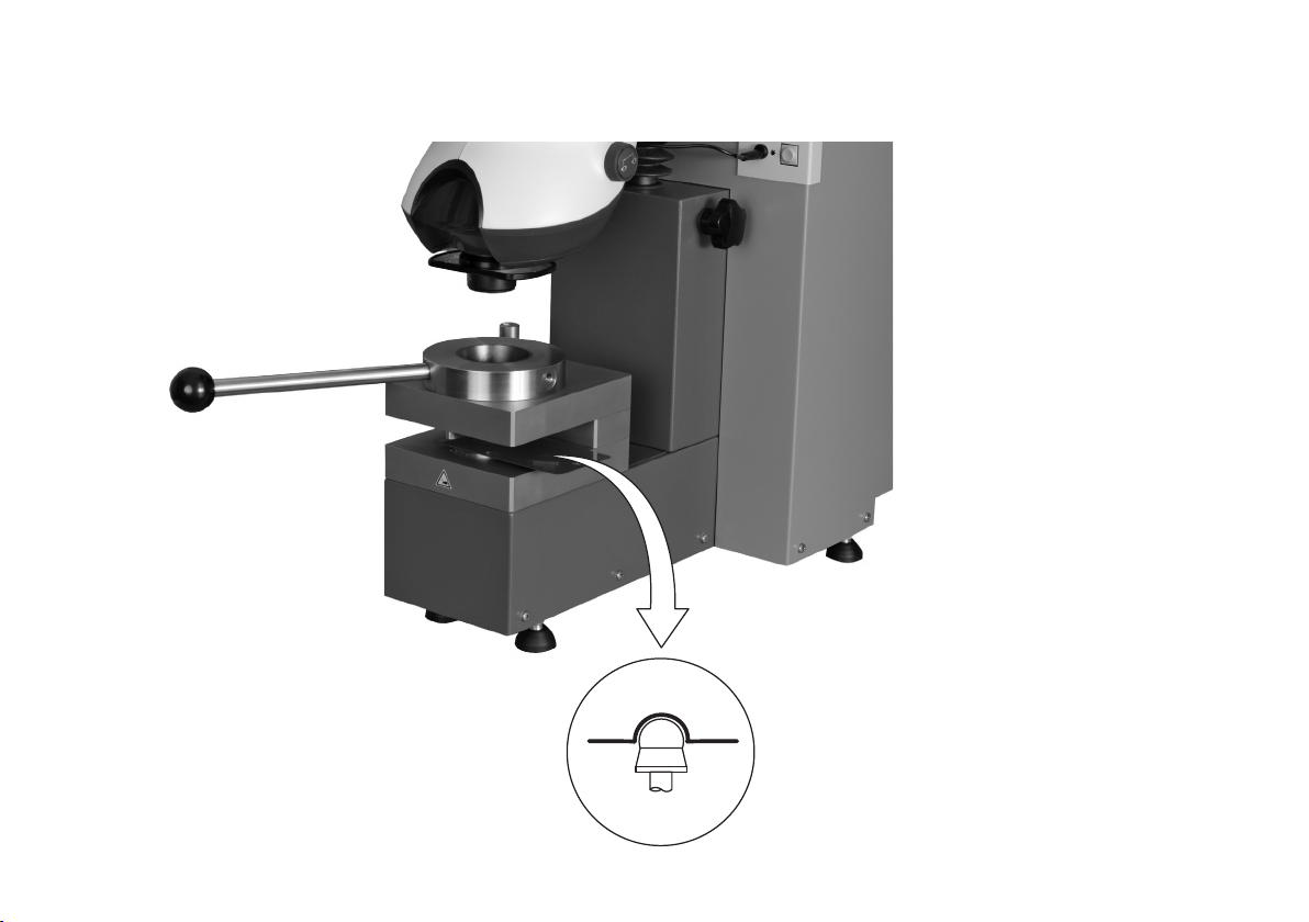
Fig. 4 Prova d imbutitura
Page 44

3.0 Prova di imbutitura
Eseguire la prova di imbutitura nel
modo seguente:
• Inserire un pannello di prova (spessore massimo 1 mm) nell’apertura
del cilindro.
• Far ruotare il tenditore eccentrico
(10) per bloccare il pannello di prova, senza stringere
eccessivamente.
• Premere il tasto START
osservare il campione mediante lo
stereomicroscopio.
• Appena risulta visibile un’incrinatura
del fi lm di vernice sul pannello di
prova, premere il tasto STOP e
leggere il valore di imbutitura sul
display digitale.
• Premere il tasto REVERSE L per
riportare indietro il punzone.
• Quando il punzone ha raggiunto la
posizione iniziale, allentare il tenditore eccentrico ed estrarre
il pannello di prova.
K e
Page 45

4.0 Display digitale
5.0 Manutenzione
Il display digitale (10) non richiede fasi
di riscaldamento o stabilizzazione.
• Se la misurazione visualizzata si
discosta da 0.00 di ± 0.10 o - - -,
contattare il Reparto di Assistenza
per istruzioni sulla manutenzione o
su eventuali riparazioni.
Verifi care l’azzeramento automatico
dell’apparecchio eseguendo un
collaudo secondo la procedura
descritta al par. 2.3.
Le operazioni saranno migliori se il
tenditore eccentrico viene pulito e olito
e occasionalmente.
Pulizia delle lenti
Gli obiettivi e le lenti devono essere
pulite con un tessuto antipolvere (ad
es. in microfi bra).
Page 46

6.0 Risoluzione dei problemi
Sintomo
La lampada del
microscopio
non si accende
Causa
Cavo del microscopio
non collegato
Rimedio
Sostituire la (le)
lampadina(e)
Connettere (V. 2.4)
Sintomo
Interruttori non
funzionanti
Nessun display digitale
Causa
Fusibile
Rimedio
Sostituire il fusibile sul
retro dell’apparecchio
Page 47

7.0 Guida agli ordini
Apparecchio per prove di
imbutitura
Accessori da ordinarsi
separatamente:
La fornitura comprende la seguente
apparecchiatura di base:
• cod. art. PF-5400
Apparecchio per prove di imbuti-
tura con testata del cilindro aperta,
comprensivo di cavo di
connessione e spina, adattatore per
portamicroscopio e display digitale
• Serie di attrezzi
• Strumento di prova standard incorporato, a norma DIN EN ISO 1520,
costituito da: punzone e sfera:
20 mm ø
matrice: 27 mm ø
anello pressore
• Istruzioni per l’uso
• cod. art. PF-5410
stereomicroscopio per ingrandi-
mento 2x e 4x, comprensivo di
portamicroscopio e lampada
Page 48

8.0 Dati tecnici
Tensione: 115 V - 230 V
60 / 50 Hz
Switch automatico!
Alimentazione: 700 VA
Microscopio
Dimensioni: A x L x P
300 x 280 x 400 mm
Peso: 4 kg
Fusibile: T 1,6 A : 250 V
(tensione 230 V)
T 3,15 A : 250 V
(tensione 115 V)
Corrente
continua: Lampade microscopio
5,1 VDC, 660 mAh
Temperatura
di esercizio: + 10 °C - + 40 °C
Temperatura
di stoccaggio: 0 °C - + 50 °C
Umidità: < 85 % umidità
relativa, non
condensante a 35 °C
Dimensioni: A x L x P
650 x 280 x 600 mm
Peso: 55 kg
Tenditore: Tenditore eccentrico
con leva da 280 mm.
Forza max. 40 Nm
Idraulica: Sistema chiuso con
protezione! Pressione
dell'olio max. 30 bar
Pannello di
prova: in accordo con DIN
EN ISO 1520
in acciaio, alluminio o
plastica, dimensioni
max. 200 x 600 x 1mm
Page 49

Page 50
D E I P
0803
215 014 802
Elektrohydrauliczny
tester do badania
tłoczności
Nr kat. PF-5400
Page 51
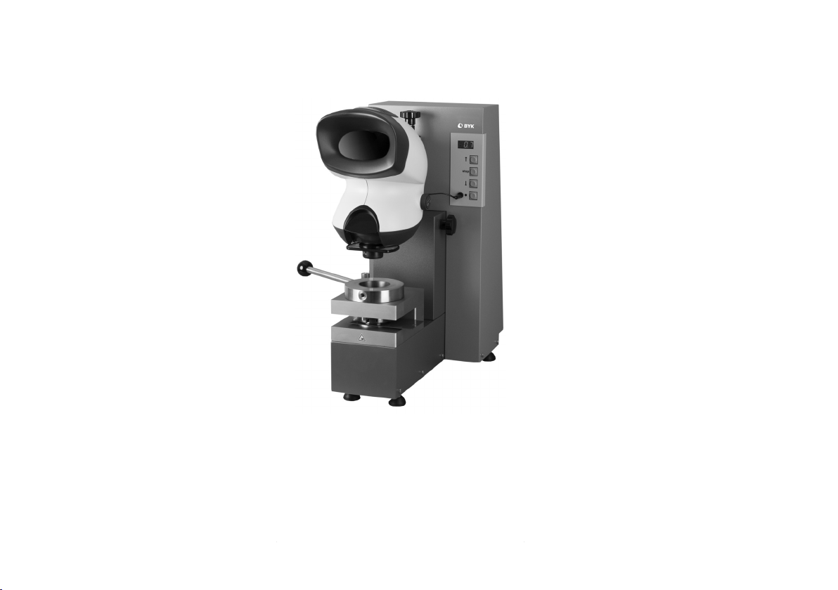
Rys. 1
Page 52

Elektrohydrauliczny
tester do badania
tłoczności
1.0 Wskazówki dotyczące
bezpieczeństwa
2.0 Przygotowanie
2.1 Zainstalowanie
2.2 Podłączenie do sieci
elektrycznej
2.3 Przebieg badania
2.4 Mikroskop stereoskopowy
3.0 Badanie tłoczności
4.0 Wskazania cyfrowe
5.0 Wykaz błędów prób
6.0 Wskazówki dotyczące dostawy
7.0 Dane techniczne
Zastrzega się zmiany techniczne.
Page 53

1.0 Wskazówki dotyczące
bezpieczeństwa
Przed włączeniem aparatu należy
upewnić się, czy podane wielkości
napięcia na aparacie są zgodne
z napięciem sieci.
Wtyk sieciowy należy włączyć do
gniazda sieciowego z przewodem uziemiającym. Uziemienie nie
może być wykonane przy pomocy
przedłużacza bez żyły ochronnej.
UWAGA!
Przypadkowe przerwanie przewodu
ochronnego wewnątrz aparatu lub
po stronie zewnętrznej albo słabe
zamocowanie, może spowodować
zagrożenie ze strony aparatu. Niedozwolone jest umyślne przerywanie.
Page 54

Regulacja, wymiana części, konserwacja i uruchomienie.
Podczas otwierania osłon lub usuwania części , szczególnie ręcznie,
można spowodować odsłonięcie
części będących pod napięciem.
Dlatego przed przystąpieniem do regulacji, konserwacji, rozruchu lub wymiany części trzeba aparat odłączyć
od wszystkich źródeł napięcia, gdy
konieczne jest otwieranie aparatu.
Jeżeli jednak regulacja, konserwacja lub naprawa ma mieć miejsce w
otwartym aparacie i pod napięciem,
to te roboty może wykonywać jedynie
fachowiec obeznany z istniejącym
niebezpieczeństwem. Kondensatory
w aparacie mogą być naładowane
jeszcze wtedy, gdy aparat jest już
odłączony od sieci. Należy upewnić
się czy zainstalowane są bezpieczniki
właściwego typu i wielkości znamionowej.
Niedopuszczalne jest użycie bezpieczników naprawianych lub zwieranie
styków w gniazdach bezpiecznikowych.
Page 55

Wady i nadzwyczajne przypadki
Jeśli istnieje podejrzenie, że nie
ma możliwości bezpiecznej pracy
aparatu, to należy go wyłączyć i
zabezpieczyć przed nieprzewidywalnym, ponownym włączeniem.
Stwierdzić, czy możliwa jest niebezpieczna praca aparatu czyli:
• że aparat ma widoczne
uszkodzenie
• że aparat nie będzie pracował
• że jest po dłuższym składowaniu
w niewłaściwych warukach
• że jest po ciężkich warunkach
transportowych.
Page 56
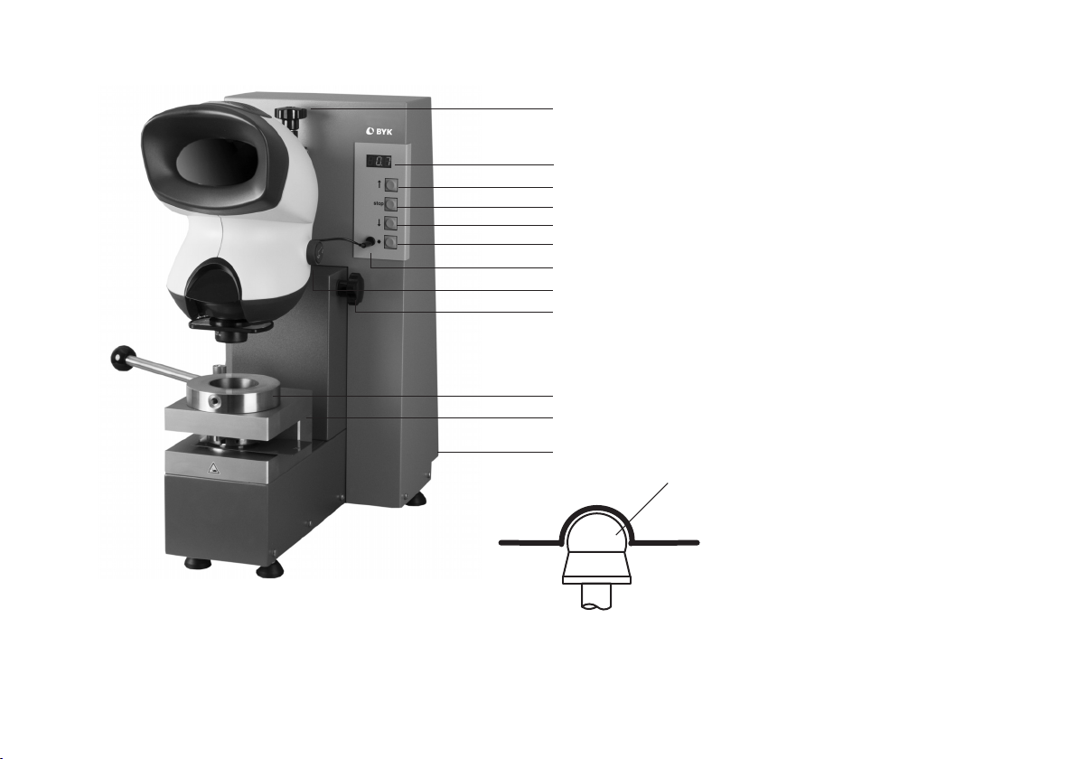
10
11
1 śruba regulacji 2- / 4-krotnego
powiększenia
1
2
3
4
5
6
7
8
9
2 wskaźnik cyfrowy „tłoczność“
3 przycisk START K
4 przycisk STOP
5 przycisk powrót L
6 przycisk oświetlenia mikroskopu
7 gniazdo przyłączowe przewodu
mikroskop - pole obsługi
8 regulator jasności oświetlenia
mikroskopu
9 śruba blokująca
Rys. 2
12
13
10 uchwyt zaciskowy mimośrodowy
11 głowica cylindra
12 wyłącznik sieciowy zał / wył
13 suwak prasy z głowicą kulistą
wg DIN EN ISO 1520
Page 57
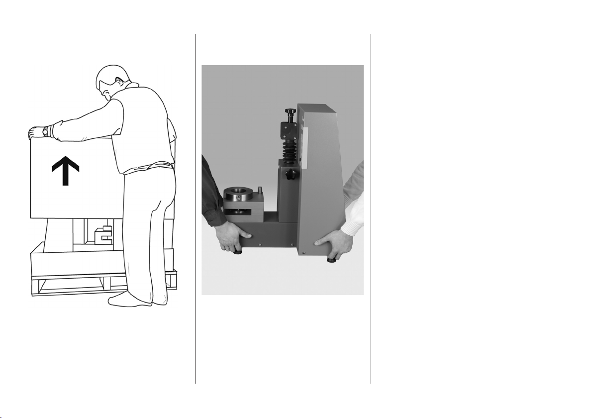
2.0 Przygotowanie
Zdjąć opakowanie
Przenosić we dwie osoby
2.1 Montaż
Elektrohydrauliczny przyrząd do
badania tłoczności model 5400 jest
dostarczany w stanie kompletnym,
z wypełnionym zbiornikiem oleju.
Należy jedynie wkręcić uchwyt ręczny
do jednego z trzech otworów na
mimośrodzie.
2.2 Podłączenie elektryczne
Aparat podłączyć do gniazda sieciowego z wtykiem uziemiającym,
przy wyłącznej pozycji wyłącznika.
Napięcie sieci musi wynosić 230 V
50/60 Hz.
Praca napięciem 115 V.
Przed włączeniem do gniazda sieciowego i uruchomieniem maszyny
trzeba wewnątrz przełączyć napięcie
z 230 V na 115 V. Od serii Nr. 980746
dostarczane będą maszyny z
automatycznym przełącznikiem
napięcia z 110 V na 240 V 50/60 Hz.
Page 58
2.3 Badanie próbne
Pierwsze badanie należy
przeprowadzić następująco:
• Sprawdzić elementy obsługi. Pozycje ich przedstawione są na Rys. 2
• Należy włączyć (12) maszynę,
wskaźnik 0,0 lub - - -
• Nacisnąć przycisk START
K
odczekać przesuw w skrajne
położenie (około 14 mm)
• Tłok przyciskiem "powrót"
sprowadzić do pozycji wskaźnika
0,0 lub - - -
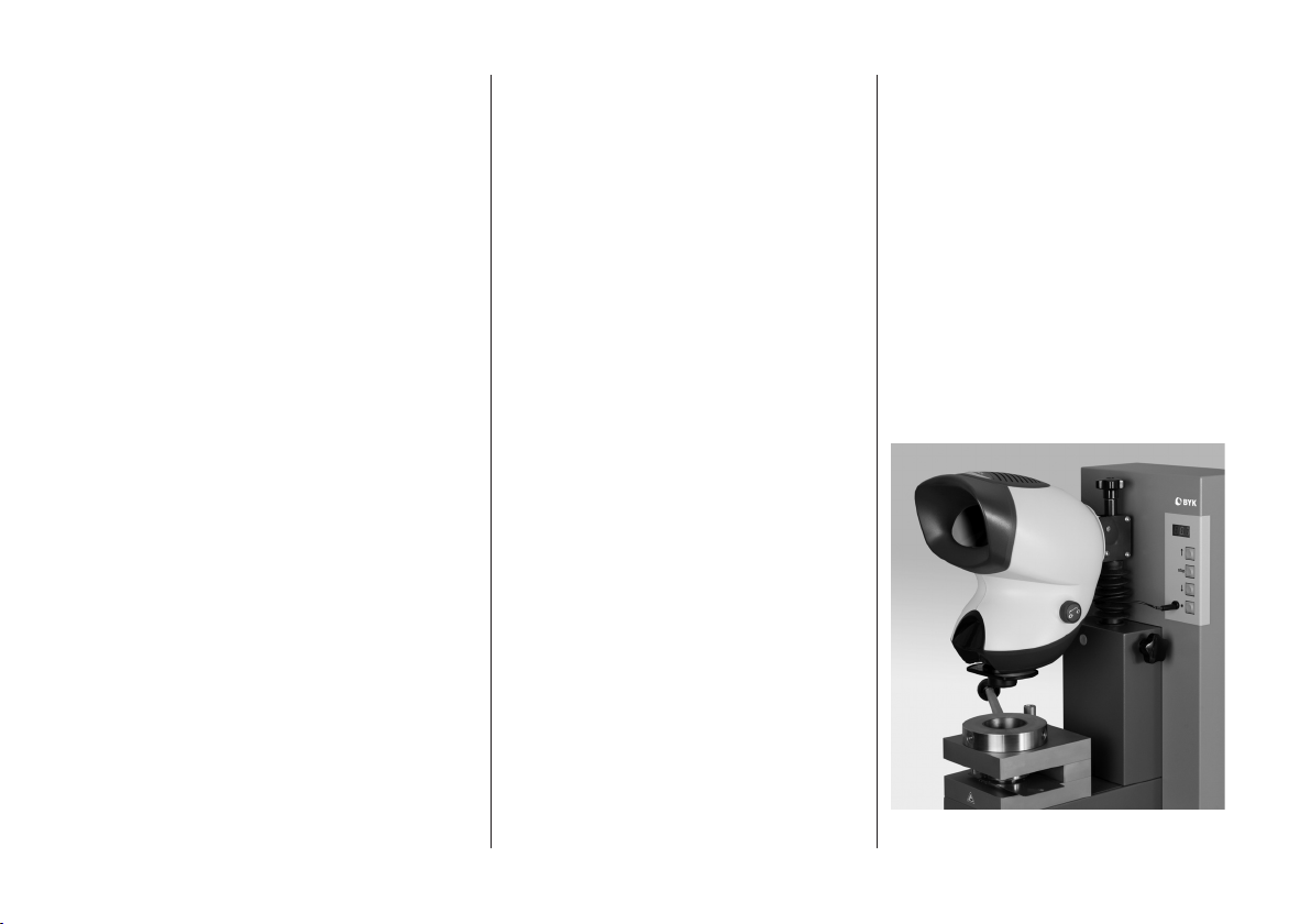
2.4 Mikroskop stereoskopowy
Mikroskop stereoskopowy (Rys. 3)
należy posadowić jak następuje:
• poluzować moletowaną śrubę,
usunąć element dystansowy,
osadzić mikroskop.
Uwaga: kołek aretujący musi
zaskoczyć w czarny element
dystansowy.
• Podkładkę / tulejkę założyć i
zamocować moletowaną śrubą.
• Soczewki (dwu i czterokrotna)
ostrożnie wkręcić w uchwyt
obiektywu (gwint drobnozwojowy).
• W polu widzenia musi być teraz
ostro widoczna kulka.
• Jeśli to konieczne, podregulować
ostrość mikroskopu pokrętłem i
ewentualnie wypozycjonować
kolumnę na odpowiednią wysokość
śrubą z gniazdem sześciokątnym
(pod białą pokrywką).
• Regulatorem ustawić właściwą
jasność światła mikroskopu.
• Aparat wyłączyć (12).
• Włączyć do gniazda przewód
łączący mikroskop z polem obsługi.
• Ustawić włącznik sieciowy z tyłu
maszyny w położenie “zał “ (ON, EIN).
• Uruchomić przycisk oświetlenia
mikroskopu.
• Wprowadzić soczewkę 2-krotną do
obiektywu.
Rys. 3 Mikroskop stereoskopowy
Page 59
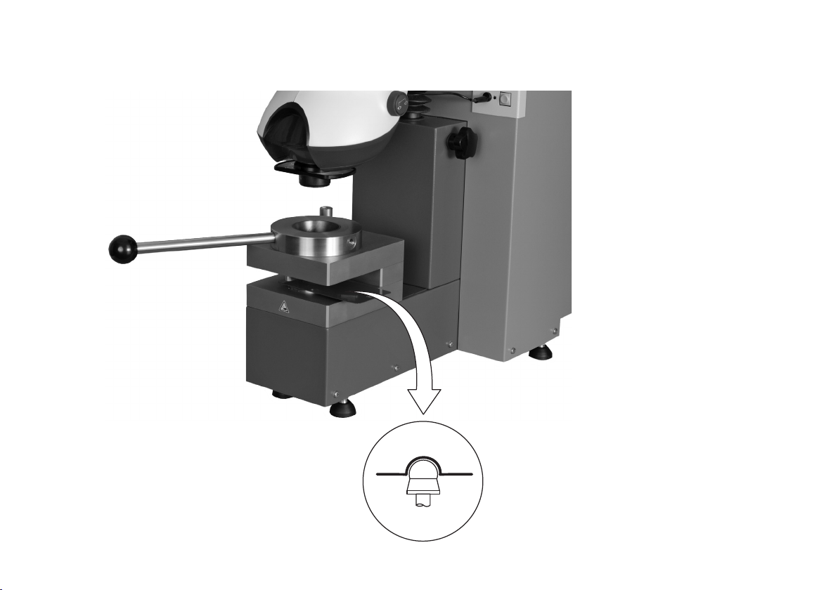
Rys. 4 Tłoczenie
Page 60

3.0 Badanie tłoczności
Przebieg badania tłoczności jest
następujący:
• Badaną blachę (max. grubość
1 mm) wsunąć do wycięcia
w cylindrze.
• Przez obracanie mimośrodem (10)
lekko ją zacisnąć.
• Nacisnąć przycisk START
obsewować przebieg próby w
mikroskopie.
• Przy pierwszym widocznym
pęknięciu powierzchni fi lmu na
badanym elemencie, nacisnąć
przycisk STOP L odczytać wartość
przetłoczenia na wskaźniku cyfrowym.
• Cofnąć tłok przyciskiem "cofnąć"
• Gdy osiągnięta zostanie pozycja ze-
rowa, zwolnić uchwyt mimośrodowy
i wyjąć badaną próbkę.
K
Page 61

4.0 Wskaźnik cyfrowy
5.0 Maintenance
Wskaźnik cyfrowy (2) nie wymaga
okresu nagrzania lub stabilizacji.
• W przypadku gdy wskaźnik cyfrowy
nie wskazuje pozycji 0,00 +/ - 0,10
lub - - -, należy poinformować
techniczną służbę serwisową.
W celu automatycznego ustawienia
punktu zerowego maszyny, należy
przeprowadzić próbny bieg, jak
opisano w punkcie 2.3.
Przyrząd będzie funkcjonować
pewniej, jeśli mimośrodowy pierścień
zaciskowy od czasu do czasu
oczyścimy i naoliwimy.
Czyszczenie optyki
Obiektywy i soczewka obserwacyjna
powinny być okresowo czyszczone
miękką ściereczką (np. do czyszczenia okularów)
Page 62

6.0 Wykaz błędów
Objaw
Brak światła
w mikroskopie
Przyczyna
Uszkodzona żarówka
(2 szt.)
Korekta
Wymienić żarówkę
Objaw
Nie działają przyciski
Nie ma wskazań LED
Przyczyna
Bezpiecznik
Korekta
Wymienić bezpieczni
z tyłu maszyny
Page 63

7.0 Wskazówki dotyczące
dostawy
Przyrząd do badania tłoczności
W ramach dostawy znajduje się
następujące wyposażenie zasadnicze:
• Nr kat. PF-5400 przyrząd do
badania tłoczności z otwartą
głowicą, kablem przyłączowym z
wtykiem, uchwytem mikroskopu i
wskaźnikiem cyfrowym.
• Zestaw narzędzi, składa się ze
śrubokręta krzyżakowego i klucza
nasadowego
• Normalne narzędzie kontrolne (już
zamontowane w maszynie)
wykonane zgodnie z DIN EN ISO
1520, składające się z tłoka z kulą
o średnicy 20 mm ø, matrycy o
średnicy 27 mm ø pierścienia
dociskowego
• Instrukcja obsługi
Na specjalne żądanie dostarcza się:
• Mikroskop stereoskopowy nr kat.
PF-5411 z powiększeniem 2- i
4-krotnym, z uchwytem
mikroskopu i oświetleniem
• Żarówka zapasowa nr kat. PF-5412
do oświetlenia mikroskopowego
12 V, 20 W np. OSRAM 41830 SP,
żywotność około 1000 godz.
Page 64

8.0 Dane techniczne
Napięcie: 115 V - 230 V
60 / 50 Hz
przełączane automatycznie
Pobór mocy: 700 VA
Bezpieczniki: T 1,6 A : 250 V
dla napiÐcia 230 V
T 3,15 A : 250 V
dla napięcia 115 V
Mikroskop:
Wymiary: W x S x G
300 x 280 x 400 mm
Ciężar: 4 kg
Pierścień zaciskowy:
mimośrodowy
pierścień zaciskowy z
dźwignią 280 mm,
moment maks. 40 Nm
Napięcie stałe: żarówki mikroskopu
5.1 V=, 660 mA
Temperatura
pracy: 10 °C – 40 °C
Temperatura
składowania: 0 °C – + 50 °C
Wilgotność: poniżej 85 %
wilgotności względnej,
bez kondensacji,
przy 35 °C
Tester tłoczności:
Wymiary: W x S x G
650 x 280 x 600 mm
Ciężar: 55 kg
Układ hydrauliczny:
zamknięty, z
zabezpieczeniem,
ciśnienie oleju maks.
30 bar
Próbka: zgodna z DIN EN ISO
1520, ze stali, alumi nium lub tworzywa
sztucznego, o maks.
wymiarach
200 x 600 x 1 mm
Page 65

EG - Konformitätserklärung
EC - Declaration of Conformity
Wir / We, BYK-Gardner GmbH, Lausitzer Straße 8, D - 82538 Geretsried
erklären im Sinne der EG-Richtlinie(n): / declare in accordance with the EC Directive(s):
• Elektromagnetische Verträglichkeit 89/336/EWG / Electromagnetic Compatibility 89/336/EEC
• Niederspannung 73/23/EWG / Low Voltage 73/23/EEC
Die Bauart des Produktes: / The construction of the product:
Elektrohydraulische Tiefungsprüfmaschine / Electro-hydraulic Cupping Tester
ist entwickelt, konstruiert und gefertigt in Übereinstimmung mit vorgenannter(n) EG-Richtlinie(n). / was developed,
constructed and produced in accordance with a.m. EC Directive(s).
Weitere entsprechende sicherheitsrelevante Normen wurden berücksichtigt. / Further safety relevant standards
were observed. EN 61010-1, IEC 61010-1,UL 61010A-1, CAN/CSA-C22.2 No. 1010-1
Eine Technische Dokumentation ist vorhanden. / A Technical Documentation is available.
BYK-Gardner GmbH
Dr. Georg Schroeder
Geschäftsführer / Managing Director
Page 66

Déclaration de conformité - Nous, BYK-Gardner GmbH, déclarons que les produits / instruments ci-dessus
F
mentionnés ont été développés, produits et construits en conformité avec les directives CEE établies.
Konformitetserklæring - Vi, BYK-Gardner GmbH, erklærer herved, at ovennævnte produkter / instrumenter
DK
er udviklet, konstrueret og produceret i overensstemmelse med de angivne EU Direktiver.
Declaración de Conformidad - Nosotros, BYK-Gardner GmbH, declaramos que los productos / aparatos
E
arriba mencionados, han sido desarrollados, construídos y fabricados en consonancia con las directrices
de la CEE indicadas.
SF
EU-yhteensopivuusvakuutus - Me, BYK-Gardner GmbH, vakuuttaa, että yllämainitut tuotteet / laitteet on
kehitetty, rakennettu ja valmistettu asetettujen EU-direktiivien mukaisesti.
Dichiarazione di conformità - Noi, BYK-Gardner GmbH, dichiariamo che i suddetti prodotti / strumenti sono
I
stati sviluppati, construiti et prodotti in conformità con le Direttive EC stabilite.
Overeenkomstigheidsverklaring - Wij, BYK-Gardner GmbH, verklaren hierbij dat bovengenoemd produkten /
NL
apparaten zijn ontworpen, gekonstrueerd en vervaardigd overeenkomstig de genoemde EG-richtlijnen.
Declaração de Conformidade - Nós, BYK-Gardner GmbH, declaramos pela presente, que os produtos /
P
aparelhos acima indicados são desenvolvidos, construídos e produzidos de acordo com as Directivas CE
mencionadas.
Δη´λωση ΕΚ−συμμο´ρφωσηs − Εμει´s, η BYK-Gardner GmbH, δηλω´νουμε με το παρο´ν ο´τι τα ωs α´νω
GR
αναφερο´μενα προι´ο´ντα / συσκευε´s αναπτυ´χθηκαν σχεδια´στηκαν και κατασκευα´στηκαν σε συμφωνι´α
με τιs προαναφερο´´μενεs οδηγι
S
Deklaration av överenstämmelse - Vi, BYK-Gardner GmbH, deklarerar härmed att ovanstående produkter /
´εs ΕΚ.
instrument har blivit utvecklade och tillverkade i enlighet med de gällande EU direktiven.
Deklaracja zgodności - My, BYK-Gardner GmbH, deklarujemy, że wyżej wymienione wyroby zostały opraco-
PL
wane, skonstruowane i wykonane zgodnie z wymienionymi wytycznymi UE.
Page 67

BYK-Gardner GmbH
Lausitzer Str. 8
D-82538 Geretsried
Germany
Tel.: 0-800-gardner
(0-800-4273637)
+49-8171-3493-0
Fax: +49-8171-3493-140
www.byk.com/instruments/
BYK-Gardner USA
9104 Guilford Road
Columbia, MD 21046
USA
Phone: 800-343-7721
301-483-6500
Fax: 800-394-8215
301-483-6555
Page 68

215 014 802 DEIP 0803
 Loading...